EP2055544A2 - Work machine and method - Google Patents
Work machine and method Download PDFInfo
- Publication number
- EP2055544A2 EP2055544A2 EP08167914A EP08167914A EP2055544A2 EP 2055544 A2 EP2055544 A2 EP 2055544A2 EP 08167914 A EP08167914 A EP 08167914A EP 08167914 A EP08167914 A EP 08167914A EP 2055544 A2 EP2055544 A2 EP 2055544A2
- Authority
- EP
- European Patent Office
- Prior art keywords
- engine
- work machine
- ivt
- output
- machine according
- Prior art date
- Legal status (The legal status is an assumption and is not a legal conclusion. Google has not performed a legal analysis and makes no representation as to the accuracy of the status listed.)
- Granted
Links
Images
Classifications
-
- F—MECHANICAL ENGINEERING; LIGHTING; HEATING; WEAPONS; BLASTING
- F16—ENGINEERING ELEMENTS AND UNITS; GENERAL MEASURES FOR PRODUCING AND MAINTAINING EFFECTIVE FUNCTIONING OF MACHINES OR INSTALLATIONS; THERMAL INSULATION IN GENERAL
- F16H—GEARING
- F16H61/00—Control functions within control units of change-speed- or reversing-gearings for conveying rotary motion ; Control of exclusively fluid gearing, friction gearing, gearings with endless flexible members or other particular types of gearing
- F16H61/66—Control functions within control units of change-speed- or reversing-gearings for conveying rotary motion ; Control of exclusively fluid gearing, friction gearing, gearings with endless flexible members or other particular types of gearing specially adapted for continuously variable gearings
-
- B—PERFORMING OPERATIONS; TRANSPORTING
- B60—VEHICLES IN GENERAL
- B60W—CONJOINT CONTROL OF VEHICLE SUB-UNITS OF DIFFERENT TYPE OR DIFFERENT FUNCTION; CONTROL SYSTEMS SPECIALLY ADAPTED FOR HYBRID VEHICLES; ROAD VEHICLE DRIVE CONTROL SYSTEMS FOR PURPOSES NOT RELATED TO THE CONTROL OF A PARTICULAR SUB-UNIT
- B60W10/00—Conjoint control of vehicle sub-units of different type or different function
- B60W10/04—Conjoint control of vehicle sub-units of different type or different function including control of propulsion units
- B60W10/06—Conjoint control of vehicle sub-units of different type or different function including control of propulsion units including control of combustion engines
-
- B—PERFORMING OPERATIONS; TRANSPORTING
- B60—VEHICLES IN GENERAL
- B60K—ARRANGEMENT OR MOUNTING OF PROPULSION UNITS OR OF TRANSMISSIONS IN VEHICLES; ARRANGEMENT OR MOUNTING OF PLURAL DIVERSE PRIME-MOVERS IN VEHICLES; AUXILIARY DRIVES FOR VEHICLES; INSTRUMENTATION OR DASHBOARDS FOR VEHICLES; ARRANGEMENTS IN CONNECTION WITH COOLING, AIR INTAKE, GAS EXHAUST OR FUEL SUPPLY OF PROPULSION UNITS IN VEHICLES
- B60K17/00—Arrangement or mounting of transmissions in vehicles
-
- B—PERFORMING OPERATIONS; TRANSPORTING
- B60—VEHICLES IN GENERAL
- B60K—ARRANGEMENT OR MOUNTING OF PROPULSION UNITS OR OF TRANSMISSIONS IN VEHICLES; ARRANGEMENT OR MOUNTING OF PLURAL DIVERSE PRIME-MOVERS IN VEHICLES; AUXILIARY DRIVES FOR VEHICLES; INSTRUMENTATION OR DASHBOARDS FOR VEHICLES; ARRANGEMENTS IN CONNECTION WITH COOLING, AIR INTAKE, GAS EXHAUST OR FUEL SUPPLY OF PROPULSION UNITS IN VEHICLES
- B60K17/00—Arrangement or mounting of transmissions in vehicles
- B60K17/04—Arrangement or mounting of transmissions in vehicles characterised by arrangement, location or kind of gearing
- B60K17/06—Arrangement or mounting of transmissions in vehicles characterised by arrangement, location or kind of gearing of change-speed gearing
-
- B—PERFORMING OPERATIONS; TRANSPORTING
- B60—VEHICLES IN GENERAL
- B60K—ARRANGEMENT OR MOUNTING OF PROPULSION UNITS OR OF TRANSMISSIONS IN VEHICLES; ARRANGEMENT OR MOUNTING OF PLURAL DIVERSE PRIME-MOVERS IN VEHICLES; AUXILIARY DRIVES FOR VEHICLES; INSTRUMENTATION OR DASHBOARDS FOR VEHICLES; ARRANGEMENTS IN CONNECTION WITH COOLING, AIR INTAKE, GAS EXHAUST OR FUEL SUPPLY OF PROPULSION UNITS IN VEHICLES
- B60K28/00—Safety devices for propulsion-unit control, specially adapted for, or arranged in, vehicles, e.g. preventing fuel supply or ignition in the event of potentially dangerous conditions
- B60K28/10—Safety devices for propulsion-unit control, specially adapted for, or arranged in, vehicles, e.g. preventing fuel supply or ignition in the event of potentially dangerous conditions responsive to conditions relating to the vehicle
- B60K28/16—Safety devices for propulsion-unit control, specially adapted for, or arranged in, vehicles, e.g. preventing fuel supply or ignition in the event of potentially dangerous conditions responsive to conditions relating to the vehicle responsive to, or preventing, spinning or skidding of wheels
-
- B—PERFORMING OPERATIONS; TRANSPORTING
- B60—VEHICLES IN GENERAL
- B60W—CONJOINT CONTROL OF VEHICLE SUB-UNITS OF DIFFERENT TYPE OR DIFFERENT FUNCTION; CONTROL SYSTEMS SPECIALLY ADAPTED FOR HYBRID VEHICLES; ROAD VEHICLE DRIVE CONTROL SYSTEMS FOR PURPOSES NOT RELATED TO THE CONTROL OF A PARTICULAR SUB-UNIT
- B60W10/00—Conjoint control of vehicle sub-units of different type or different function
- B60W10/10—Conjoint control of vehicle sub-units of different type or different function including control of change-speed gearings
- B60W10/101—Infinitely variable gearings
- B60W10/103—Infinitely variable gearings of fluid type
-
- B—PERFORMING OPERATIONS; TRANSPORTING
- B60—VEHICLES IN GENERAL
- B60W—CONJOINT CONTROL OF VEHICLE SUB-UNITS OF DIFFERENT TYPE OR DIFFERENT FUNCTION; CONTROL SYSTEMS SPECIALLY ADAPTED FOR HYBRID VEHICLES; ROAD VEHICLE DRIVE CONTROL SYSTEMS FOR PURPOSES NOT RELATED TO THE CONTROL OF A PARTICULAR SUB-UNIT
- B60W30/00—Purposes of road vehicle drive control systems not related to the control of a particular sub-unit, e.g. of systems using conjoint control of vehicle sub-units
- B60W30/18—Propelling the vehicle
- B60W30/188—Controlling power parameters of the driveline, e.g. determining the required power
- B60W30/1882—Controlling power parameters of the driveline, e.g. determining the required power characterised by the working point of the engine, e.g. by using engine output chart
-
- B—PERFORMING OPERATIONS; TRANSPORTING
- B60—VEHICLES IN GENERAL
- B60W—CONJOINT CONTROL OF VEHICLE SUB-UNITS OF DIFFERENT TYPE OR DIFFERENT FUNCTION; CONTROL SYSTEMS SPECIALLY ADAPTED FOR HYBRID VEHICLES; ROAD VEHICLE DRIVE CONTROL SYSTEMS FOR PURPOSES NOT RELATED TO THE CONTROL OF A PARTICULAR SUB-UNIT
- B60W30/00—Purposes of road vehicle drive control systems not related to the control of a particular sub-unit, e.g. of systems using conjoint control of vehicle sub-units
- B60W30/18—Propelling the vehicle
- B60W30/188—Controlling power parameters of the driveline, e.g. determining the required power
- B60W30/1886—Controlling power supply to auxiliary devices
-
- B—PERFORMING OPERATIONS; TRANSPORTING
- B60—VEHICLES IN GENERAL
- B60W—CONJOINT CONTROL OF VEHICLE SUB-UNITS OF DIFFERENT TYPE OR DIFFERENT FUNCTION; CONTROL SYSTEMS SPECIALLY ADAPTED FOR HYBRID VEHICLES; ROAD VEHICLE DRIVE CONTROL SYSTEMS FOR PURPOSES NOT RELATED TO THE CONTROL OF A PARTICULAR SUB-UNIT
- B60W2510/00—Input parameters relating to a particular sub-units
- B60W2510/06—Combustion engines, Gas turbines
- B60W2510/0604—Throttle position
-
- B—PERFORMING OPERATIONS; TRANSPORTING
- B60—VEHICLES IN GENERAL
- B60W—CONJOINT CONTROL OF VEHICLE SUB-UNITS OF DIFFERENT TYPE OR DIFFERENT FUNCTION; CONTROL SYSTEMS SPECIALLY ADAPTED FOR HYBRID VEHICLES; ROAD VEHICLE DRIVE CONTROL SYSTEMS FOR PURPOSES NOT RELATED TO THE CONTROL OF A PARTICULAR SUB-UNIT
- B60W2510/00—Input parameters relating to a particular sub-units
- B60W2510/06—Combustion engines, Gas turbines
- B60W2510/0638—Engine speed
-
- B—PERFORMING OPERATIONS; TRANSPORTING
- B60—VEHICLES IN GENERAL
- B60W—CONJOINT CONTROL OF VEHICLE SUB-UNITS OF DIFFERENT TYPE OR DIFFERENT FUNCTION; CONTROL SYSTEMS SPECIALLY ADAPTED FOR HYBRID VEHICLES; ROAD VEHICLE DRIVE CONTROL SYSTEMS FOR PURPOSES NOT RELATED TO THE CONTROL OF A PARTICULAR SUB-UNIT
- B60W2510/00—Input parameters relating to a particular sub-units
- B60W2510/10—Change speed gearings
- B60W2510/1015—Input shaft speed, e.g. turbine speed
-
- B—PERFORMING OPERATIONS; TRANSPORTING
- B60—VEHICLES IN GENERAL
- B60W—CONJOINT CONTROL OF VEHICLE SUB-UNITS OF DIFFERENT TYPE OR DIFFERENT FUNCTION; CONTROL SYSTEMS SPECIALLY ADAPTED FOR HYBRID VEHICLES; ROAD VEHICLE DRIVE CONTROL SYSTEMS FOR PURPOSES NOT RELATED TO THE CONTROL OF A PARTICULAR SUB-UNIT
- B60W2510/00—Input parameters relating to a particular sub-units
- B60W2510/20—Steering systems
-
- B—PERFORMING OPERATIONS; TRANSPORTING
- B60—VEHICLES IN GENERAL
- B60W—CONJOINT CONTROL OF VEHICLE SUB-UNITS OF DIFFERENT TYPE OR DIFFERENT FUNCTION; CONTROL SYSTEMS SPECIALLY ADAPTED FOR HYBRID VEHICLES; ROAD VEHICLE DRIVE CONTROL SYSTEMS FOR PURPOSES NOT RELATED TO THE CONTROL OF A PARTICULAR SUB-UNIT
- B60W2540/00—Input parameters relating to occupants
- B60W2540/10—Accelerator pedal position
-
- B—PERFORMING OPERATIONS; TRANSPORTING
- B60—VEHICLES IN GENERAL
- B60W—CONJOINT CONTROL OF VEHICLE SUB-UNITS OF DIFFERENT TYPE OR DIFFERENT FUNCTION; CONTROL SYSTEMS SPECIALLY ADAPTED FOR HYBRID VEHICLES; ROAD VEHICLE DRIVE CONTROL SYSTEMS FOR PURPOSES NOT RELATED TO THE CONTROL OF A PARTICULAR SUB-UNIT
- B60W2540/00—Input parameters relating to occupants
- B60W2540/18—Steering angle
-
- B—PERFORMING OPERATIONS; TRANSPORTING
- B60—VEHICLES IN GENERAL
- B60W—CONJOINT CONTROL OF VEHICLE SUB-UNITS OF DIFFERENT TYPE OR DIFFERENT FUNCTION; CONTROL SYSTEMS SPECIALLY ADAPTED FOR HYBRID VEHICLES; ROAD VEHICLE DRIVE CONTROL SYSTEMS FOR PURPOSES NOT RELATED TO THE CONTROL OF A PARTICULAR SUB-UNIT
- B60W2710/00—Output or target parameters relating to a particular sub-units
- B60W2710/10—Change speed gearings
- B60W2710/1022—Input torque
-
- B—PERFORMING OPERATIONS; TRANSPORTING
- B60—VEHICLES IN GENERAL
- B60Y—INDEXING SCHEME RELATING TO ASPECTS CROSS-CUTTING VEHICLE TECHNOLOGY
- B60Y2200/00—Type of vehicle
- B60Y2200/40—Special vehicles
- B60Y2200/41—Construction vehicles, e.g. graders, excavators
-
- Y—GENERAL TAGGING OF NEW TECHNOLOGICAL DEVELOPMENTS; GENERAL TAGGING OF CROSS-SECTIONAL TECHNOLOGIES SPANNING OVER SEVERAL SECTIONS OF THE IPC; TECHNICAL SUBJECTS COVERED BY FORMER USPC CROSS-REFERENCE ART COLLECTIONS [XRACs] AND DIGESTS
- Y10—TECHNICAL SUBJECTS COVERED BY FORMER USPC
- Y10S—TECHNICAL SUBJECTS COVERED BY FORMER USPC CROSS-REFERENCE ART COLLECTIONS [XRACs] AND DIGESTS
- Y10S903/00—Hybrid electric vehicles, HEVS
- Y10S903/902—Prime movers comprising electrical and internal combustion motors
- Y10S903/903—Prime movers comprising electrical and internal combustion motors having energy storing means, e.g. battery, capacitor
- Y10S903/904—Component specially adapted for hev
- Y10S903/909—Gearing
- Y10S903/91—Orbital, e.g. planetary gears
-
- Y—GENERAL TAGGING OF NEW TECHNOLOGICAL DEVELOPMENTS; GENERAL TAGGING OF CROSS-SECTIONAL TECHNOLOGIES SPANNING OVER SEVERAL SECTIONS OF THE IPC; TECHNICAL SUBJECTS COVERED BY FORMER USPC CROSS-REFERENCE ART COLLECTIONS [XRACs] AND DIGESTS
- Y10—TECHNICAL SUBJECTS COVERED BY FORMER USPC
- Y10S—TECHNICAL SUBJECTS COVERED BY FORMER USPC CROSS-REFERENCE ART COLLECTIONS [XRACs] AND DIGESTS
- Y10S903/00—Hybrid electric vehicles, HEVS
- Y10S903/902—Prime movers comprising electrical and internal combustion motors
- Y10S903/903—Prime movers comprising electrical and internal combustion motors having energy storing means, e.g. battery, capacitor
- Y10S903/904—Component specially adapted for hev
- Y10S903/915—Specific drive or transmission adapted for hev
- Y10S903/917—Specific drive or transmission adapted for hev with transmission for changing gear ratio
- Y10S903/918—Continuously variable
-
- Y—GENERAL TAGGING OF NEW TECHNOLOGICAL DEVELOPMENTS; GENERAL TAGGING OF CROSS-SECTIONAL TECHNOLOGIES SPANNING OVER SEVERAL SECTIONS OF THE IPC; TECHNICAL SUBJECTS COVERED BY FORMER USPC CROSS-REFERENCE ART COLLECTIONS [XRACs] AND DIGESTS
- Y10—TECHNICAL SUBJECTS COVERED BY FORMER USPC
- Y10S—TECHNICAL SUBJECTS COVERED BY FORMER USPC CROSS-REFERENCE ART COLLECTIONS [XRACs] AND DIGESTS
- Y10S903/00—Hybrid electric vehicles, HEVS
- Y10S903/902—Prime movers comprising electrical and internal combustion motors
- Y10S903/903—Prime movers comprising electrical and internal combustion motors having energy storing means, e.g. battery, capacitor
- Y10S903/946—Characterized by control of driveline clutch
-
- Y—GENERAL TAGGING OF NEW TECHNOLOGICAL DEVELOPMENTS; GENERAL TAGGING OF CROSS-SECTIONAL TECHNOLOGIES SPANNING OVER SEVERAL SECTIONS OF THE IPC; TECHNICAL SUBJECTS COVERED BY FORMER USPC CROSS-REFERENCE ART COLLECTIONS [XRACs] AND DIGESTS
- Y10—TECHNICAL SUBJECTS COVERED BY FORMER USPC
- Y10S—TECHNICAL SUBJECTS COVERED BY FORMER USPC CROSS-REFERENCE ART COLLECTIONS [XRACs] AND DIGESTS
- Y10S903/00—Hybrid electric vehicles, HEVS
- Y10S903/902—Prime movers comprising electrical and internal combustion motors
- Y10S903/903—Prime movers comprising electrical and internal combustion motors having energy storing means, e.g. battery, capacitor
- Y10S903/951—Assembly or relative location of components
Definitions
- the present invention relates to work machines, and, more particularly, to work machines including an internal combustion engine coupled with an infinitely variable transmission (IVT).
- IVT infinitely variable transmission
- the step load response of an IC engine in transient after a load impact is a feature mostly influenced by the engine displacement, the hardware of the engine (e.g., whether it has a standard turbocharger, a turbocharger with waste gate or variable geometry, etc.), and by the software strategy for driving the air and fuel actuators (e.g., exhaust gas recirculation, turbocharger with variable geometry turbine (VGT), fuel injector configuration, etc.) with respect to the requirements of emissions legislation (e.g., visible smoke, nitrous oxides (NOx), etc.), noise or vibrations.
- the load impact may be the result of a drivetrain load (e.g., an implement towed behind the work machine) or an external load (e.g., an auxiliary hydraulic load such as a front end loader, backhoe attachment, etc.)
Landscapes
- Engineering & Computer Science (AREA)
- Mechanical Engineering (AREA)
- Chemical & Material Sciences (AREA)
- Combustion & Propulsion (AREA)
- Transportation (AREA)
- Automation & Control Theory (AREA)
- General Engineering & Computer Science (AREA)
- Control Of Vehicle Engines Or Engines For Specific Uses (AREA)
- Operation Control Of Excavators (AREA)
- Control Of Transmission Device (AREA)
- Auxiliary Drives, Propulsion Controls, And Safety Devices (AREA)
- Combined Controls Of Internal Combustion Engines (AREA)
- Control Of Fluid Gearings (AREA)
Abstract
Description
- The present invention relates to work machines, and, more particularly, to work machines including an internal combustion engine coupled with an infinitely variable transmission (IVT).
- A work machine, such as a construction work machine, an agricultural work machine or a forestry work machine, typically includes a prime mover in the form of an internal combustion (IC) engine. The IC engine may either be in the form of a compression ignition engine (i.e., diesel engine) or a spark ignition engine (i.e., gasoline engine). For most heavy work machines, the prime mover is in the form of a diesel engine having better lugging, pull-down and torque characteristics for associated work operations.
- The step load response of an IC engine in transient after a load impact is a feature mostly influenced by the engine displacement, the hardware of the engine (e.g., whether it has a standard turbocharger, a turbocharger with waste gate or variable geometry, etc.), and by the software strategy for driving the air and fuel actuators (e.g., exhaust gas recirculation, turbocharger with variable geometry turbine (VGT), fuel injector configuration, etc.) with respect to the requirements of emissions legislation (e.g., visible smoke, nitrous oxides (NOx), etc.), noise or vibrations. The load impact may be the result of a drivetrain load (e.g., an implement towed behind the work machine) or an external load (e.g., an auxiliary hydraulic load such as a front end loader, backhoe attachment, etc.)
- Engine systems as a whole react in a linear manner during the application of a transient load. Initially, the load is applied to the drive shaft of the IC engine. The IC engine speed decreases when the load increases. The engine speed drop is influenced by whether the governor is isochronous or has a speed droop. The air flow is increased to provide additional air to the IC engine by modifying the air actuators. A time delay is necessary to achieve the new air flow set point. The fuel injection quantity, which is nearly immediate, is increased with respect to both the smoke limit and maximum allowable fuel quantity. The engine then recovers to the engine speed set point. The parameters associated with an engine step load response in transient after a load impact are the speed drop and the time to recover to the engine set point.
- An IC engine may be coupled with an IVT which provides continuous variable output speed from 0 to maximum in a stepless fashion. An IVT typically includes hydrostatic and mechanical gearing components. The hydrostatic components convert rotating shaft power to hydraulic flow and vice versa. The power flow through an IVT can be through the hydrostatic components only, through the mechanical components only, or through a combination of both depending on the design and output speed.
- One example of an IVT for use in a work machine is a hydromechanical transmission which includes a hydraulic module coupled with a planetary gear set. Another example of an IVT for a work machine is a hydrostatic transmission which includes a hydraulic module coupled with a gear set.
- A work machine including an IVT may be prone to loss of traction control and wheel slip when the IVT ratio changes to match load conditions. The IVT controller senses engine speed and deepens the IVT ratio as engine speed decreases under load. When at low ground speeds, the amount of power required for the work machine is a low percentage of what the engine can generate, so the engine may not lug down when the output torque from the engine increases. The operator will then not be aware that the torque at the wheels is increasing. In this case, the drive wheels can lose traction and spin out without notice. This is undesirable for certain operations.
- What is needed in the art is a work machine configured with an IVT which is not prone to losing traction in low ground speed conditions and a respective method.
- It is therefore the object of the present invention to comply with one or all of these needs respectively.
- This object is met according to the invention by the teaching of
claim 1 or 8 respectively, while features developing the solution in an advantageous manner are set forth in the further claims. - The invention in one form is directed to a work machine including an IC engine having an output, and an IVT coupled with the IC engine output. The IVT may include a hydraulic module and a mechanical drivetrain module. A pressure transducer may be associated with and provide an output signal representing a hydraulic pressure within the hydraulic module. At least one electrical processing circuit may be configured for controlling the IC engine output, dependent upon the output signal from the pressure transducer.
- The invention in another form is directed to a method of operating a work machine including an IC engine having an output, and an IVT coupled with the IC engine output. The IVT may include a hydraulic module and a mechanical drive train module. The method may includes the steps of: setting a torque limit associated with the IVT; sensing a hydraulic pressure within the hydraulic module; and controlling an output of the IC engine, dependent upon the sensed hydraulic pressure and the torque limit.
- An embodiment of the invention described below are shown in the drawings, in which
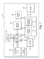
- Fig. 1
- is a schematic illustration of an embodiment of a work machine of the present invention; and
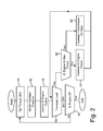
- Fig. 2
- illustrates a flowchart of an embodiment of the method of operation of a work machine of the present invention.
- Referring now to
Fig. 1 , there is shown a schematic illustration of an embodiment of awork machine 10 of the present invention.Work machine 10 could be a road grader, or a construction work machine such as a John Deere 644J front end loader, or a different type of work machine such as an agricultural, forestry or mining work machine. -
Work machine 10 includes anIC engine 12 which is coupled with an IVT 14, typically through anoutput crankshaft 16 fromIC engine 12.IC engine 12 is assumed to be a diesel engine in the illustrated embodiment, but could also be a gasoline engine, propane engine, etc.IC engine 12 is sized and configured according to the application. - IVT 14 generally includes a
hydraulic module 18 and a mechanicaldrive train module 20. IVT 14 is assumed to be a hydromechanical transmission in the embodiment shown, but could also be a hydrostatic transmission, or other type of IVT. IVT 14 may be of conventional design, and thus is not described in great detail herein. IVT 14 has an output which is coupled with at least one other downstreamdrive train component 22, which in turn is coupled with a plurality ofdrive wheels 24, one of which is shown inFig. 1 . Of course, it will be appreciated that in the case of a track-type work vehicle,drive train component 22 may be coupled with a ground engaging track. - IVT 14 also provides output power to one or more
external loads 26, which in turn thus provide an additional load onIC engine 12.External loads 26 typically are in the form of hydraulic loads, such as a front end loader, back hoe boom, grain unloading auger, tree felling saw motor, etc. The total load placed uponIC engine 12 thus is a function of both tractive loads and external hydraulic loads. - An
electrical processing circuit 28 is configured as one or more controllers. In the embodiment shown,controller 28 includes an engine control unit (ECU) 30 which electronically controls operation ofIC engine 12, and is coupled with a plurality of sensors (not specifically shown) associated with operation ofIC engine 12. For example, ECU 30 may be coupled with a sensor indicating engine control parameters such as an air flow rate within one or more intake manifolds, engine speed, fueling rate and/or timing, exhaust gas recirculation (EGR) rate, turbocharger blade position, etc. Additionally,ECU 30 may receive output signals from vehicle control unit (VCU) 32 representing vehicle control parameters input by an operator, such as a commanded ground speed (indicated by a position of the throttle and/or hydrostat lever) or a commanded direction of work machine 10 (indicated by an angular orientation of the steering wheel). - Similarly, transmission control unit (TCU) 34 electronically controls operation of
IVT 14, and is coupled with a plurality of sensors associated with operation ofIVT 14. ECU 30 and TCU 34 are coupled together via a bus structure providing two-way data flow, such as controller area network (CAN)bus 36. -
Pressure transducer 38 is placed in communication withhydraulic module 18, preferably in communication with the pressure loop near the fixed hydrostatic unit.Pressure transducer 38 provides an output signal toTCU 34 representing the hydraulic pressure withinhydraulic module 18.Pressure transducer 38 may be of conventional design, and is selected for the particular application. - A torque
control input device 40 allows an operator to adjust the torque from IVT 14, which is controlled at least in part through controlling the output torque fromIC engine 12. In the embodiment shown, torquecontrol input device 40 is configured as a rotatable torque control dial which is positioned within an operator's station.Torque control dial 40 may have visible lines, numbers, serrations, etc. ranging between a minimum torque control setting and a maximum torque control setting. Alternatively, torquecontrol input device 40 could be configured as an electronic touch screen, or any number of other configurations. - Although the various electronic components such as
ECU 30,VCU 32 andTCU 34 are shown coupled together using wired connections, it should also be understood that wireless connections may be used for certain applications. Further, some of the internal electronic and fluid connections within the components ofFig.1 are not shown for simplicity sake. - Referring now to
Fig. 2 , an embodiment of the method of the present invention for operation ofwork machine 10 will be described in greater detail. The flowchart shown inFig. 2 accommodates most operating conditions, except whereIC engine 12 is operating at or near idle conditions, in which case the output fromIC engine 12 is not limited. - The torque limit from the output of
IVT 14 is initially set using torque control dial 40 (block 50). The control knob setting corresponds to a desired output torque fromIVT 14. Less aggressive settings prevent wheel slip in certain ground conditions, and more aggressive settings increase the maximum desired torque. Turning the knob to the less aggressive setting actually limits the pressure that is in the fixed hydrostatic unit that is directly connected to the planetary sun gear. - During operation, the hydraulic pressure within
hydraulic module 18 is sensed using pressure transducer 38 (block 52). An output signal frompressure transducer 38 is outputted toTCU 34, which in turn outputs a signal toECU 30.ECU 30 controls the output fromIC engine 12, dependent upon both the sensed pressure and the set torque limit (block 54).Pressure transducer 38 is very accurate and very responsive, thus allowing more accurate and timely control of limiting torque at the output shaft fromIVT 14. When the sensed pressure reaches the calculated desired torque limit, then the fuel rate toIC engine 12 is reduced to in turn reduce the amount of input torque toIVT 14, thus limiting the output torque fromIVT 14. - The method of operation of the present invention may also accommodate transient loads during operation (decision block 56). If a transient load such as an external hydraulic load is sensed, then a query is made as to whether the
IC engine 12 is at a maximum torque output (decision block 58). IfIC engine 12 is already operating at a maximum torque for a given engine speed, then it is not possible to further increase the torque output fromIC engine 12, so instead the input/output (I/O) ratio fromIVT 14 is increased (block 60). On the other hand, ifIC engine 12 is not operating at a maximum torque for a given engine speed, then the torque output fromIC engine 12 is increased to match the transient load (block 62). - In the event no transient load is detected, or the transient load passes (line 64), then the method continues until the
IC engine 12 is turned OFF (decision block 66). While theIC engine 12 continues to run, control loops back to block 50, where a new or the old torque limit is set. - With the method of the present invention as described above, limiting the input torque from
IC engine 12 based on readings frompressure transducer 38 is an extremely accurate way to control the maximum output torque fromIVT 14, thus controlling tractive effort to meet the operator's demands under current conditions and maximize performance. - Having described the preferred embodiment, it will become apparent that various modifications can be made without departing from the scope of the invention as defined in the accompanying claims.
Claims (11)
- A work machine (10), comprising an internal combustion (IC) engine (12) having an output; an infinitely variable transmission (IVT) (14) coupled with said IC engine output, said IVT (14) including a hydraulic module (18) and a mechanical drive train module (20); a pressure transducer (38) associated with and providing an output signal representing a hydraulic pressure within said hydraulic module (18); and at least one electrical processing circuit (28) configured for controlling said IC engine output, dependent upon said output signal from said pressure transducer (18).
- The work machine according to claim 1, characterized by a torque control input device (40) in communication with and providing an output signal to said at least one electrical processing circuit (28), said at least one electrical processing circuit (28) configured for controlling said IC engine output, dependent upon each of said output signal from said pressure transducer (38) and said output signal from said torque control input device (40), wherein preferably said torque control input device (40) comprises an operator adjustable torque control dial, said torque control dial preferably including a minimum torque control setting and a maximum torque control setting.
- The work machine according to claim 1 or 2, characterized in that said at least one electrical processing circuit (28) includes at least one of an engine control unit (ECU) (30) associated with said IC engine (12), and a transmission control unit (TCU) (34) associated with said IVT (14), wherein preferably said TCU (34) receives said output signal from said pressure transducer (38), communicates with said ECU (30), and said ECU (30) controls said IC engine output.
- The work machine according to one or several of the previous claims,
characterized in that said at least one electrical processing circuit (28) controls said IC engine output by controlling a fuel rate to said IC engine (12), wherein preferably said IC engine output comprises a crankshaft (16), said hydraulic module (18) being coupled with said crankshaft. - The work machine according to one or several of the previous claims, characterized in that said IVT (14) comprises one of a hydromechanical transmission and a hydrostatic transmission.
- The work machine according to one or several of the previous claims, characterized in that said maximum allowable load is associated with a maximum torque at a given operating speed for said IC engine (12).
- The work machine according to one or several of the previous claims, characterized in that said work machine (10) comprises one of a construction work machine, an agricultural work machine and a forestry work machine.
- A method of operating a work machine including an internal combustion (IC) engine (12) having an output, and an infinitely variable transmission (IVT) (14) coupled with the IC engine output, the IVT (14) including a hydraulic module (18) and a mechanical drive train module (20), said method characterized by the steps of setting a torque limit associated with the IVT (14); sensing a hydraulic pressure within the hydraulic module (18) ; and controlling an output of the IC engine (12), dependent upon said sensed hydraulic pressure and said torque limit.
- The method of operating a work machine according to claim 8, characterized that said torque limit is set using an operator adjustable torque control dial.
- The method of operating a work machine according to claim 8 or 9, characterized in that said hydraulic pressure is sensed using a pressure transducer (38) associated with and providing an output signal representing a hydraulic pressure within said hydraulic module (18).
- The method of operating a work machine according to on or several of the claims 8 to 10, characterized in that said controlling step is carried out using at least one of an engine control unit (ECU) (30) associated with said IC engine (12), and a transmission control unit (TCU) (34) associated with said IVT (14).
Applications Claiming Priority (1)
| Application Number | Priority Date | Filing Date | Title |
|---|---|---|---|
| US11/931,396 US8060284B2 (en) | 2007-10-31 | 2007-10-31 | Work machine with torque limiting control for an infinitely variable transmission |
Publications (3)
| Publication Number | Publication Date |
|---|---|
| EP2055544A2 true EP2055544A2 (en) | 2009-05-06 |
| EP2055544A3 EP2055544A3 (en) | 2010-09-08 |
| EP2055544B1 EP2055544B1 (en) | 2016-10-12 |
Family
ID=40229948
Family Applications (1)
| Application Number | Title | Priority Date | Filing Date |
|---|---|---|---|
| EP08167914.4A Active EP2055544B1 (en) | 2007-10-31 | 2008-10-30 | Work machine and method |
Country Status (8)
| Country | Link |
|---|---|
| US (1) | US8060284B2 (en) |
| EP (1) | EP2055544B1 (en) |
| JP (1) | JP2009144703A (en) |
| KR (1) | KR20090045019A (en) |
| CN (1) | CN101424085B (en) |
| CA (1) | CA2641121C (en) |
| MX (1) | MX2008013627A (en) |
| RU (1) | RU2491180C2 (en) |
Cited By (1)
| Publication number | Priority date | Publication date | Assignee | Title |
|---|---|---|---|---|
| EP2918466A4 (en) * | 2013-06-28 | 2016-10-26 | Komatsu Mfg Co Ltd | SITE VEHICLE AND CONTROL METHOD THEREOF |
Families Citing this family (15)
| Publication number | Priority date | Publication date | Assignee | Title |
|---|---|---|---|---|
| ES2620506T3 (en) | 2009-06-17 | 2017-06-28 | Hiroshima University | Diluent dilution of sperm and method for artificial insemination using the same |
| US8515637B2 (en) * | 2010-12-23 | 2013-08-20 | Caterpillar Inc. | Machine control system and method |
| US8606448B2 (en) | 2011-06-29 | 2013-12-10 | Caterpillar Inc. | System and method for managing power in machine having electric and/or hydraulic devices |
| US8909434B2 (en) | 2011-06-29 | 2014-12-09 | Caterpillar, Inc. | System and method for controlling power in machine having electric and/or hydraulic devices |
| CN104160183B (en) | 2012-03-07 | 2017-08-25 | 克拉克设备公司 | Power management for drive system |
| EP3077601A2 (en) * | 2013-12-03 | 2016-10-12 | Clark Equipment Company | Vehicle start system |
| US9688276B2 (en) | 2015-02-26 | 2017-06-27 | Caterpillar Inc. | System and method for controlling engine and transmission system of a machine |
| WO2016156347A1 (en) * | 2015-04-03 | 2016-10-06 | Cnh Industrial Italia S.P.A. | High drivability control for cvt tractors |
| US9994104B2 (en) | 2015-09-03 | 2018-06-12 | Deere & Company | System and method of reacting to wheel slip in a traction vehicle |
| US10407072B2 (en) | 2015-09-03 | 2019-09-10 | Deere & Company | System and method of regulating wheel slip in a traction vehicle |
| US9845008B2 (en) | 2015-09-03 | 2017-12-19 | Deere & Company | System and method of detecting load forces on a traction vehicle to predict wheel slip |
| US10112615B2 (en) | 2015-09-03 | 2018-10-30 | Deere & Company | System and method of reacting to wheel slip in a traction vehicle |
| DE102017208988A1 (en) * | 2017-05-29 | 2018-11-29 | Robert Bosch Gmbh | Method for controlling a hydrostatic drive |
| DE102020211077A1 (en) * | 2020-09-02 | 2022-03-03 | Zf Friedrichshafen Ag | Method for traction-related speed control of a working machine |
| US12172647B2 (en) | 2021-03-19 | 2024-12-24 | Caterpillar Inc. | Method and system for engine and machine control |
Citations (1)
| Publication number | Priority date | Publication date | Assignee | Title |
|---|---|---|---|---|
| WO2007074608A1 (en) | 2005-12-26 | 2007-07-05 | Komatsu Ltd. | Construction vehicle |
Family Cites Families (29)
| Publication number | Priority date | Publication date | Assignee | Title |
|---|---|---|---|---|
| US3258286A (en) * | 1964-06-25 | 1966-06-28 | Paul T Coward | Golf ball retrieving device |
| US4833613A (en) * | 1986-04-18 | 1989-05-23 | Eaton Corporation | Method for controlling AMT system including throttle position sensor signal fault detection and tolerance |
| JPH0363320A (en) * | 1989-07-31 | 1991-03-19 | Komatsu Ltd | Operation device for power shovel |
| US5797110A (en) * | 1995-11-17 | 1998-08-18 | Eaton Corporation | Engine torque control |
| US5791887A (en) * | 1996-10-17 | 1998-08-11 | Scroll Technologies | Scroll element having a relieved thrust surface |
| EP0838613B1 (en) * | 1996-10-25 | 2002-08-14 | Aisin Aw Co., Ltd. | Infinitely variable transmission |
| US5967756A (en) | 1997-07-01 | 1999-10-19 | Caterpillar Inc. | Power management control system for a hydraulic work machine |
| US5987756A (en) * | 1997-07-23 | 1999-11-23 | Mcculloch Corporation | Head and head assembly for a string trimmer |
| JPH1150868A (en) * | 1997-08-04 | 1999-02-23 | Yanmar Agricult Equip Co Ltd | Engine speed adjustment configuration for traveling vehicles |
| GB2337090A (en) * | 1998-05-08 | 1999-11-10 | Torotrak Dev Ltd | Hydraulic control circuit for a continuously-variable ratio transmission |
| US6405844B1 (en) | 1999-09-10 | 2002-06-18 | Komatsu Ltd. | Working vehicle |
| US6260440B1 (en) * | 1999-12-17 | 2001-07-17 | Caterpillar Inc. | Method and apparatus for shifting ranges in a continuously variable transmission |
| JP3678122B2 (en) | 2000-07-10 | 2005-08-03 | 日産自動車株式会社 | Torque control device for continuously variable transmission with infinite gear ratio |
| US6666793B2 (en) | 2001-02-22 | 2003-12-23 | Nissan Motor Co., Ltd. | Control of infinitely variable transmission |
| JP3731746B2 (en) * | 2002-09-26 | 2006-01-05 | 日産自動車株式会社 | Control device for engine and belt type continuously variable transmission |
| JP4208179B2 (en) | 2002-10-28 | 2009-01-14 | 株式会社小松製作所 | Hydraulic drive vehicle |
| US6901324B2 (en) * | 2003-09-30 | 2005-05-31 | Caterpillar Inc | System and method for predictive load management |
| JP2006118685A (en) * | 2004-10-25 | 2006-05-11 | Shin Caterpillar Mitsubishi Ltd | Fluid circuit of working machine |
| DE602005024041D1 (en) * | 2004-11-22 | 2010-11-18 | Bosch Rexroth Corp | HYDROELECTRIC HYBRID DRIVE SYSTEM FOR A MOTOR VEHICLE |
| JP4654722B2 (en) * | 2005-03-22 | 2011-03-23 | 株式会社アドヴィックス | Brake device for vehicle |
| JP4404834B2 (en) * | 2005-10-06 | 2010-01-27 | ジヤトコ株式会社 | Line pressure control device for belt type continuously variable transmission |
| CA2582158C (en) * | 2006-03-17 | 2014-05-13 | Benoit Carpentier | Closed-loop cutting system |
| US9126598B2 (en) | 2006-06-05 | 2015-09-08 | Deere & Company | Power management for infinitely variable transmission (IVT) equipped machines |
| US7614843B2 (en) * | 2007-01-05 | 2009-11-10 | Caterpillar Inc. | Freely rotatable closed grapple head and machine using same |
| US20090112414A1 (en) * | 2007-10-31 | 2009-04-30 | Briton Todd Eastman | Work Machine With Torque Limiting Control For An Infinitely Variable Transmssion |
| US8457848B2 (en) * | 2007-10-31 | 2013-06-04 | Deere & Company | Work machine with IVT output automatically adjusted dependent upon engine load |
| US7972240B2 (en) * | 2007-12-19 | 2011-07-05 | Deere & Company | Work machine with power limit control using an infinitely variable transmission |
| JP4447039B2 (en) * | 2008-02-12 | 2010-04-07 | トヨタ自動車株式会社 | Power output device and vehicle |
| US8352155B2 (en) * | 2009-05-21 | 2013-01-08 | Deere & Company | Engine for an agricultural harvester having isochronous torque curve with power bulge |
-
2007
- 2007-10-31 US US11/931,396 patent/US8060284B2/en active Active
-
2008
- 2008-10-16 CA CA2641121A patent/CA2641121C/en not_active Expired - Fee Related
- 2008-10-23 KR KR1020080104209A patent/KR20090045019A/en not_active Ceased
- 2008-10-23 MX MX2008013627A patent/MX2008013627A/en active IP Right Grant
- 2008-10-29 CN CN200810172070.XA patent/CN101424085B/en active Active
- 2008-10-30 RU RU2008143150/11A patent/RU2491180C2/en not_active IP Right Cessation
- 2008-10-30 EP EP08167914.4A patent/EP2055544B1/en active Active
- 2008-10-31 JP JP2008280983A patent/JP2009144703A/en active Pending
Patent Citations (1)
| Publication number | Priority date | Publication date | Assignee | Title |
|---|---|---|---|---|
| WO2007074608A1 (en) | 2005-12-26 | 2007-07-05 | Komatsu Ltd. | Construction vehicle |
Cited By (3)
| Publication number | Priority date | Publication date | Assignee | Title |
|---|---|---|---|---|
| EP2918466A4 (en) * | 2013-06-28 | 2016-10-26 | Komatsu Mfg Co Ltd | SITE VEHICLE AND CONTROL METHOD THEREOF |
| US9732499B2 (en) | 2013-06-28 | 2017-08-15 | Komatsu Ltd. | Work vehicle and control method for same |
| US10407864B2 (en) | 2013-06-28 | 2019-09-10 | Komatsu Ltd. | Work vehicle and control method for same |
Also Published As
| Publication number | Publication date |
|---|---|
| CN101424085A (en) | 2009-05-06 |
| EP2055544A3 (en) | 2010-09-08 |
| CN101424085B (en) | 2014-05-28 |
| CA2641121A1 (en) | 2009-04-30 |
| US20090112415A1 (en) | 2009-04-30 |
| JP2009144703A (en) | 2009-07-02 |
| US8060284B2 (en) | 2011-11-15 |
| CA2641121C (en) | 2016-11-08 |
| EP2055544B1 (en) | 2016-10-12 |
| RU2008143150A (en) | 2010-05-10 |
| RU2491180C2 (en) | 2013-08-27 |
| KR20090045019A (en) | 2009-05-07 |
| MX2008013627A (en) | 2009-05-11 |
Similar Documents
| Publication | Publication Date | Title |
|---|---|---|
| US8060284B2 (en) | Work machine with torque limiting control for an infinitely variable transmission | |
| CA2645970C (en) | Work machine with power limit control using an infinitely varible transmission | |
| EP2055545A2 (en) | Work Machine and Method | |
| EP2055543B1 (en) | Work Machine and Method | |
| US8070651B2 (en) | Work machine coast and brake control with an infinitely variable transmission | |
| AU2010201937A1 (en) | Engine for an agricultural harvester having isochronous torque curve with power bulge | |
| EP2253197A1 (en) | Agricultural harvester with electric power transfer between dual power units |
Legal Events
| Date | Code | Title | Description |
|---|---|---|---|
| PUAI | Public reference made under article 153(3) epc to a published international application that has entered the european phase |
Free format text: ORIGINAL CODE: 0009012 |
|
| AK | Designated contracting states |
Kind code of ref document: A2 Designated state(s): AT BE BG CH CY CZ DE DK EE ES FI FR GB GR HR HU IE IS IT LI LT LU LV MC MT NL NO PL PT RO SE SI SK TR |
|
| AX | Request for extension of the european patent |
Extension state: AL BA MK RS |
|
| PUAL | Search report despatched |
Free format text: ORIGINAL CODE: 0009013 |
|
| AK | Designated contracting states |
Kind code of ref document: A3 Designated state(s): AT BE BG CH CY CZ DE DK EE ES FI FR GB GR HR HU IE IS IT LI LT LU LV MC MT NL NO PL PT RO SE SI SK TR |
|
| AX | Request for extension of the european patent |
Extension state: AL BA MK RS |
|
| RIC1 | Information provided on ipc code assigned before grant |
Ipc: B60W 10/06 20060101AFI20090123BHEP Ipc: B60W 10/10 20060101ALI20100803BHEP Ipc: B60W 30/18 20060101ALI20100803BHEP Ipc: B60K 28/16 20060101ALI20100803BHEP |
|
| 17P | Request for examination filed |
Effective date: 20110308 |
|
| 17Q | First examination report despatched |
Effective date: 20110330 |
|
| AKX | Designation fees paid |
Designated state(s): AT BE BG CH CY CZ DE DK EE ES FI FR GB GR HR HU IE IS IT LI LT LU LV MC MT NL NO PL PT RO SE SI SK TR |
|
| GRAP | Despatch of communication of intention to grant a patent |
Free format text: ORIGINAL CODE: EPIDOSNIGR1 |
|
| INTG | Intention to grant announced |
Effective date: 20160503 |
|
| GRAS | Grant fee paid |
Free format text: ORIGINAL CODE: EPIDOSNIGR3 |
|
| GRAA | (expected) grant |
Free format text: ORIGINAL CODE: 0009210 |
|
| AK | Designated contracting states |
Kind code of ref document: B1 Designated state(s): AT BE BG CH CY CZ DE DK EE ES FI FR GB GR HR HU IE IS IT LI LT LU LV MC MT NL NO PL PT RO SE SI SK TR |
|
| REG | Reference to a national code |
Ref country code: GB Ref legal event code: FG4D |
|
| REG | Reference to a national code |
Ref country code: CH Ref legal event code: EP |
|
| REG | Reference to a national code |
Ref country code: AT Ref legal event code: REF Ref document number: 836207 Country of ref document: AT Kind code of ref document: T Effective date: 20161015 |
|
| REG | Reference to a national code |
Ref country code: IE Ref legal event code: FG4D |
|
| REG | Reference to a national code |
Ref country code: DE Ref legal event code: R096 Ref document number: 602008046759 Country of ref document: DE |
|
| REG | Reference to a national code |
Ref country code: LT Ref legal event code: MG4D |
|
| REG | Reference to a national code |
Ref country code: NL Ref legal event code: MP Effective date: 20161012 |
|
| PG25 | Lapsed in a contracting state [announced via postgrant information from national office to epo] |
Ref country code: LV Free format text: LAPSE BECAUSE OF FAILURE TO SUBMIT A TRANSLATION OF THE DESCRIPTION OR TO PAY THE FEE WITHIN THE PRESCRIBED TIME-LIMIT Effective date: 20161012 Ref country code: BE Free format text: LAPSE BECAUSE OF NON-PAYMENT OF DUE FEES Effective date: 20161031 |
|
| REG | Reference to a national code |
Ref country code: AT Ref legal event code: MK05 Ref document number: 836207 Country of ref document: AT Kind code of ref document: T Effective date: 20161012 |
|
| PG25 | Lapsed in a contracting state [announced via postgrant information from national office to epo] |
Ref country code: LT Free format text: LAPSE BECAUSE OF FAILURE TO SUBMIT A TRANSLATION OF THE DESCRIPTION OR TO PAY THE FEE WITHIN THE PRESCRIBED TIME-LIMIT Effective date: 20161012 Ref country code: SE Free format text: LAPSE BECAUSE OF FAILURE TO SUBMIT A TRANSLATION OF THE DESCRIPTION OR TO PAY THE FEE WITHIN THE PRESCRIBED TIME-LIMIT Effective date: 20161012 Ref country code: NO Free format text: LAPSE BECAUSE OF FAILURE TO SUBMIT A TRANSLATION OF THE DESCRIPTION OR TO PAY THE FEE WITHIN THE PRESCRIBED TIME-LIMIT Effective date: 20170112 Ref country code: GR Free format text: LAPSE BECAUSE OF FAILURE TO SUBMIT A TRANSLATION OF THE DESCRIPTION OR TO PAY THE FEE WITHIN THE PRESCRIBED TIME-LIMIT Effective date: 20170113 |
|
| PG25 | Lapsed in a contracting state [announced via postgrant information from national office to epo] |
Ref country code: IS Free format text: LAPSE BECAUSE OF FAILURE TO SUBMIT A TRANSLATION OF THE DESCRIPTION OR TO PAY THE FEE WITHIN THE PRESCRIBED TIME-LIMIT Effective date: 20170212 Ref country code: PL Free format text: LAPSE BECAUSE OF FAILURE TO SUBMIT A TRANSLATION OF THE DESCRIPTION OR TO PAY THE FEE WITHIN THE PRESCRIBED TIME-LIMIT Effective date: 20161012 Ref country code: PT Free format text: LAPSE BECAUSE OF FAILURE TO SUBMIT A TRANSLATION OF THE DESCRIPTION OR TO PAY THE FEE WITHIN THE PRESCRIBED TIME-LIMIT Effective date: 20170213 Ref country code: FI Free format text: LAPSE BECAUSE OF FAILURE TO SUBMIT A TRANSLATION OF THE DESCRIPTION OR TO PAY THE FEE WITHIN THE PRESCRIBED TIME-LIMIT Effective date: 20161012 Ref country code: NL Free format text: LAPSE BECAUSE OF FAILURE TO SUBMIT A TRANSLATION OF THE DESCRIPTION OR TO PAY THE FEE WITHIN THE PRESCRIBED TIME-LIMIT Effective date: 20161012 Ref country code: HR Free format text: LAPSE BECAUSE OF FAILURE TO SUBMIT A TRANSLATION OF THE DESCRIPTION OR TO PAY THE FEE WITHIN THE PRESCRIBED TIME-LIMIT Effective date: 20161012 Ref country code: ES Free format text: LAPSE BECAUSE OF FAILURE TO SUBMIT A TRANSLATION OF THE DESCRIPTION OR TO PAY THE FEE WITHIN THE PRESCRIBED TIME-LIMIT Effective date: 20161012 Ref country code: BE Free format text: LAPSE BECAUSE OF FAILURE TO SUBMIT A TRANSLATION OF THE DESCRIPTION OR TO PAY THE FEE WITHIN THE PRESCRIBED TIME-LIMIT Effective date: 20161012 Ref country code: AT Free format text: LAPSE BECAUSE OF FAILURE TO SUBMIT A TRANSLATION OF THE DESCRIPTION OR TO PAY THE FEE WITHIN THE PRESCRIBED TIME-LIMIT Effective date: 20161012 |
|
| REG | Reference to a national code |
Ref country code: CH Ref legal event code: PL |
|
| REG | Reference to a national code |
Ref country code: DE Ref legal event code: R097 Ref document number: 602008046759 Country of ref document: DE |
|
| REG | Reference to a national code |
Ref country code: IE Ref legal event code: MM4A |
|
| PG25 | Lapsed in a contracting state [announced via postgrant information from national office to epo] |
Ref country code: MC Free format text: LAPSE BECAUSE OF FAILURE TO SUBMIT A TRANSLATION OF THE DESCRIPTION OR TO PAY THE FEE WITHIN THE PRESCRIBED TIME-LIMIT Effective date: 20161012 Ref country code: SK Free format text: LAPSE BECAUSE OF FAILURE TO SUBMIT A TRANSLATION OF THE DESCRIPTION OR TO PAY THE FEE WITHIN THE PRESCRIBED TIME-LIMIT Effective date: 20161012 Ref country code: DK Free format text: LAPSE BECAUSE OF FAILURE TO SUBMIT A TRANSLATION OF THE DESCRIPTION OR TO PAY THE FEE WITHIN THE PRESCRIBED TIME-LIMIT Effective date: 20161012 Ref country code: RO Free format text: LAPSE BECAUSE OF FAILURE TO SUBMIT A TRANSLATION OF THE DESCRIPTION OR TO PAY THE FEE WITHIN THE PRESCRIBED TIME-LIMIT Effective date: 20161012 Ref country code: CH Free format text: LAPSE BECAUSE OF NON-PAYMENT OF DUE FEES Effective date: 20161031 Ref country code: LI Free format text: LAPSE BECAUSE OF NON-PAYMENT OF DUE FEES Effective date: 20161031 Ref country code: EE Free format text: LAPSE BECAUSE OF FAILURE TO SUBMIT A TRANSLATION OF THE DESCRIPTION OR TO PAY THE FEE WITHIN THE PRESCRIBED TIME-LIMIT Effective date: 20161012 Ref country code: CZ Free format text: LAPSE BECAUSE OF FAILURE TO SUBMIT A TRANSLATION OF THE DESCRIPTION OR TO PAY THE FEE WITHIN THE PRESCRIBED TIME-LIMIT Effective date: 20161012 |
|
| PLBE | No opposition filed within time limit |
Free format text: ORIGINAL CODE: 0009261 |
|
| STAA | Information on the status of an ep patent application or granted ep patent |
Free format text: STATUS: NO OPPOSITION FILED WITHIN TIME LIMIT |
|
| PG25 | Lapsed in a contracting state [announced via postgrant information from national office to epo] |
Ref country code: IT Free format text: LAPSE BECAUSE OF FAILURE TO SUBMIT A TRANSLATION OF THE DESCRIPTION OR TO PAY THE FEE WITHIN THE PRESCRIBED TIME-LIMIT Effective date: 20161012 Ref country code: BG Free format text: LAPSE BECAUSE OF FAILURE TO SUBMIT A TRANSLATION OF THE DESCRIPTION OR TO PAY THE FEE WITHIN THE PRESCRIBED TIME-LIMIT Effective date: 20170112 Ref country code: LU Free format text: LAPSE BECAUSE OF NON-PAYMENT OF DUE FEES Effective date: 20161030 |
|
| REG | Reference to a national code |
Ref country code: FR Ref legal event code: ST Effective date: 20170802 |
|
| 26N | No opposition filed |
Effective date: 20170713 |
|
| GBPC | Gb: european patent ceased through non-payment of renewal fee |
Effective date: 20170112 |
|
| PG25 | Lapsed in a contracting state [announced via postgrant information from national office to epo] |
Ref country code: FR Free format text: LAPSE BECAUSE OF NON-PAYMENT OF DUE FEES Effective date: 20161212 |
|
| PG25 | Lapsed in a contracting state [announced via postgrant information from national office to epo] |
Ref country code: GB Free format text: LAPSE BECAUSE OF NON-PAYMENT OF DUE FEES Effective date: 20170112 Ref country code: SI Free format text: LAPSE BECAUSE OF FAILURE TO SUBMIT A TRANSLATION OF THE DESCRIPTION OR TO PAY THE FEE WITHIN THE PRESCRIBED TIME-LIMIT Effective date: 20161012 Ref country code: IE Free format text: LAPSE BECAUSE OF NON-PAYMENT OF DUE FEES Effective date: 20161030 |
|
| PG25 | Lapsed in a contracting state [announced via postgrant information from national office to epo] |
Ref country code: HU Free format text: LAPSE BECAUSE OF FAILURE TO SUBMIT A TRANSLATION OF THE DESCRIPTION OR TO PAY THE FEE WITHIN THE PRESCRIBED TIME-LIMIT; INVALID AB INITIO Effective date: 20081030 Ref country code: CY Free format text: LAPSE BECAUSE OF FAILURE TO SUBMIT A TRANSLATION OF THE DESCRIPTION OR TO PAY THE FEE WITHIN THE PRESCRIBED TIME-LIMIT Effective date: 20161012 |
|
| PG25 | Lapsed in a contracting state [announced via postgrant information from national office to epo] |
Ref country code: MT Free format text: LAPSE BECAUSE OF NON-PAYMENT OF DUE FEES Effective date: 20161031 Ref country code: TR Free format text: LAPSE BECAUSE OF FAILURE TO SUBMIT A TRANSLATION OF THE DESCRIPTION OR TO PAY THE FEE WITHIN THE PRESCRIBED TIME-LIMIT Effective date: 20161012 |
|
| PGFP | Annual fee paid to national office [announced via postgrant information from national office to epo] |
Ref country code: DE Payment date: 20250919 Year of fee payment: 18 |