EP2055469A1 - Extruding tread components directly into a tire mold - Google Patents
Extruding tread components directly into a tire mold Download PDFInfo
- Publication number
- EP2055469A1 EP2055469A1 EP08167639A EP08167639A EP2055469A1 EP 2055469 A1 EP2055469 A1 EP 2055469A1 EP 08167639 A EP08167639 A EP 08167639A EP 08167639 A EP08167639 A EP 08167639A EP 2055469 A1 EP2055469 A1 EP 2055469A1
- Authority
- EP
- European Patent Office
- Prior art keywords
- extrudate
- tire mold
- head
- tire
- extruder
- Prior art date
- Legal status (The legal status is an assumption and is not a legal conclusion. Google has not performed a legal analysis and makes no representation as to the accuracy of the status listed.)
- Withdrawn
Links
- 238000000034 method Methods 0.000 claims abstract description 22
- 150000001875 compounds Chemical class 0.000 claims abstract description 9
- 238000003892 spreading Methods 0.000 claims description 8
- WWTBZEKOSBFBEM-SPWPXUSOSA-N (2s)-2-[[2-benzyl-3-[hydroxy-[(1r)-2-phenyl-1-(phenylmethoxycarbonylamino)ethyl]phosphoryl]propanoyl]amino]-3-(1h-indol-3-yl)propanoic acid Chemical compound N([C@@H](CC=1C2=CC=CC=C2NC=1)C(=O)O)C(=O)C(CP(O)(=O)[C@H](CC=1C=CC=CC=1)NC(=O)OCC=1C=CC=CC=1)CC1=CC=CC=C1 WWTBZEKOSBFBEM-SPWPXUSOSA-N 0.000 description 3
- 235000014121 butter Nutrition 0.000 description 3
- 229940126208 compound 22 Drugs 0.000 description 3
- 238000010438 heat treatment Methods 0.000 description 2
- JOYRKODLDBILNP-UHFFFAOYSA-N Ethyl urethane Chemical compound CCOC(N)=O JOYRKODLDBILNP-UHFFFAOYSA-N 0.000 description 1
- 230000000712 assembly Effects 0.000 description 1
- 238000000429 assembly Methods 0.000 description 1
- 230000015572 biosynthetic process Effects 0.000 description 1
- 235000008429 bread Nutrition 0.000 description 1
- 239000011248 coating agent Substances 0.000 description 1
- 238000000576 coating method Methods 0.000 description 1
- 230000001419 dependent effect Effects 0.000 description 1
- 238000001125 extrusion Methods 0.000 description 1
- 238000004519 manufacturing process Methods 0.000 description 1
- 239000000463 material Substances 0.000 description 1
- 238000005096 rolling process Methods 0.000 description 1
- XLYOFNOQVPJJNP-UHFFFAOYSA-N water Substances O XLYOFNOQVPJJNP-UHFFFAOYSA-N 0.000 description 1
Images



Classifications
-
- B—PERFORMING OPERATIONS; TRANSPORTING
- B29—WORKING OF PLASTICS; WORKING OF SUBSTANCES IN A PLASTIC STATE IN GENERAL
- B29D—PRODUCING PARTICULAR ARTICLES FROM PLASTICS OR FROM SUBSTANCES IN A PLASTIC STATE
- B29D30/00—Producing pneumatic or solid tyres or parts thereof
- B29D30/06—Pneumatic tyres or parts thereof (e.g. produced by casting, moulding, compression moulding, injection moulding, centrifugal casting)
- B29D30/52—Unvulcanised treads, e.g. on used tyres; Retreading
-
- B—PERFORMING OPERATIONS; TRANSPORTING
- B29—WORKING OF PLASTICS; WORKING OF SUBSTANCES IN A PLASTIC STATE IN GENERAL
- B29D—PRODUCING PARTICULAR ARTICLES FROM PLASTICS OR FROM SUBSTANCES IN A PLASTIC STATE
- B29D30/00—Producing pneumatic or solid tyres or parts thereof
- B29D30/06—Pneumatic tyres or parts thereof (e.g. produced by casting, moulding, compression moulding, injection moulding, centrifugal casting)
- B29D30/52—Unvulcanised treads, e.g. on used tyres; Retreading
- B29D2030/523—Ring-shaped treads
Definitions
- This invention pertains to the art of methods and apparatuses regarding the manufacture of tires, and more particularly to methods and apparatuses regarding the application of tire tread components directly from an extruder/gear pump into a tire mold.
- tires are made by first assembling a tire carcass on a flat drum. The drum is then expanded to place the carcass into the required toroidal shape. Separately, a tread is formed, typically using an extruder, and a belt package is made. The belt package is placed over the carcass and the tread is subsequently placed over the belt package. This creates an unvulcanized or "green” tire. The green tire is then placed into a tire mold where internal pressure is used to push the green tire against the mold, forcing the tread into the specific mold pattern. After sufficient time and temperature within the mold, the green tire becomes vulcanized, or cured.
- One disadvantage of this method is related to the fact that tires are generally assembled from many separate components. In order to maintain high quality for tires, each of these components must be precisely located and accurately shaped within the completed tire. Maintaining the required shapes and obtaining sufficient accuracy in the positions of the components is extremely difficult in practice because of the readily deformable nature of the unvulcanized material that is used and because of the conventional gross changes in shape which are impressed on the tire during assembly. What is needed, then, is an improved way to position tire components to minimize these disadvantages.
- the invention relates to a method according to claim 1 and a system according to claim 11.
- the movement of the tire mold is controlled to correspond to the first extrudate delivery.
- the step of controlling movement of the tire mold to correspond to the first extrudate delivery comprises the step of rotating the tire mold corresponding to the first extrudate delivery.
- a tire tread component is formed in one revolution of the tire mold.
- a tire tread component is formed with more than one revolution of the tire mold.
- the extrudate is spread onto the tire mold with a spread surface.
- the method further comprises the steps of providing a nozzle connected to the head for use in applying the first extrudate and/or providing a preferably heated friction shoe or a roller shoe near the nozzle and/or spreading the extrudate to the tire mold with a spread surface on the friction shoe or on the roller shoe.
- the step of providing a first extruder operatively connected to the head with the die assembly comprises the step of providing the first extruder with a gear pump and the step of applying the first extrudate directly from the die assembly into the tire mold to form the tire tread component comprises the step of delivering a predetermined, preferably a precisely predetermined amount of extrudate using the gear pump at a predetermined speed that corresponds to the rotational speed of the tire mold or to the speed of the moving of the tire mold relative to the die assembly.
- the extruder comprises a gear pump.
- the extruder comprises an extrudate size adjustment mechanism that can be used to adjust the size of an opening through which the extrudate exits the head.
- the system comprises a nozzle connected to the head for use in applying the first extrudate at a width less than the tread width, wherein said nozzle preferably comprises a spread surface for use in spreading the first extrudate to the tire mold) and/or a second extruder operatively connected to the head and/or the head comprising a fixed head portion and a rotating head portion that is rotatable with respect to the fixed head portion and wherein a nozzle is attached to the rotating head portion.
- One advantage of this invention is that a tire tread can be applied directly to a tire mold eliminating the need to expand or stretch the tread into the mold.
- Another advantage of this invention in one embodiment, is that by adjusting the size of the extrudate opening, the head can be used to apply multiple tread components to multiple tire molds.
- extrudate can be directly applied to a tire mold as a laminate that is gradually built up, layer upon layer or layer beside layer until the tire component is fully applied to the tire mold.
- Still another advantage of this invention is that a precise amount of extrudate can be delivered using a gear pump at a predetermined speed that corresponds to the rotational speed of the tire mold.
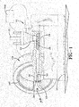
- FIGURE 1 shows an extruder assembly 10 applying an extrudate 12 directly to a tire mold 100.
- directly it is meant that the extrudate moves non-stop, without being stored, out of the extruder assembly 10 and into the tire mold 100 .
- the extruder assembly 10 shown is applying a tread extrudate 12 directly against or into the tread forming portion 102 of the mold 100 .
- a tire is thus being built from the outside in to form a very low tension tire.
- By placing the tread extrudate 12 directly into the mold 100 no expansion or stretching of the tread extrudate 12 is required.
- the resulting tire thus has very good uniformity.
- the extruder assembly 10 may include a housing 14 supported on a base 16. Within the housing 16 a screw 20 may be used to masticate and move a compound 22, which may be an elastomeric compound such as rubber. The compound 22 may be fed into a feed chute 24 by which it contacts the screw 20 and is thereby moved as the screw 20 rotates. The compound may then enter and flow through a flow channel 52 formed in a head 30 and then through a die assembly 50 to create the extrudate 12 . It should be noted that this invention will work with any type of extruder assembly that delivers the extrudate 12 directly into the tire mold 100. In another embodiment, two or more extruder assemblies can be used.
- a duplex extruder or triplex extruder can be used to feed the same head 30.
- This provides a convenient way to extrude multiple compounds into a single extrudate 12, such as a tread extrudate comprising a tread base formed of one compound and a tread cap formed of another compound.
- the tire mold 100 is a segmented tire mold having multiple radially movable tread forming segments 104 that when closed form an annular tread ring 110 having a tread ring width W1 .
- the tread ring 110 provides the tread forming portion 102 of the tire mold 100 .
- the operation of a segmented mold as well as other types of molds is well known and thus will not be described in detail.
- this invention will work well with any orientation of the tire mold 100 including placing the mold 100 so that the central axis 108 is substantially parallel to a ground surface, as shown in FIGURE 1 , or placing the mold 100 so that the central axis 108 is substantially perpendicular to a ground surface, as shown in FIGURES 3-4 .
- a rotation device 120 of any type chosen with sound engineering judgment may be used to rotate the tire mold 100 and/or the tread ring 110 for purposes to be discussed further below.
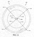
- the rotation device 120 comprises a hub 122 having multiple arms 124 .
- the hub 122 may be positioned near the central axis 108 of the tire mold 100.
- the radial distal ends of the arms 124 may have gripping portions 126 that are secured to the radially outer surface of the tire mold 100.
- To rotate the mold 100 it is only necessary to attach the rotation device 120 to the tire mold 100 and then rotate the hub 122 in any manner chosen with sound engineering judgment.
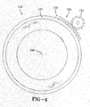
- the rotation device 120 comprises a gear ring 128 formed on or placed on the radially outer surface of the tire mold 100. Only a segment of the gear ring 128 is shown in FIGURE 4 but it is to be understood that the gear ring 128 may extend substantially around the periphery of the tire mold 100 .
- a pinion gear 130 having gear teeth that engage the gear teeth on the gear ring 128, can be rotated in any manner chosen with sound engineering judgment to thereby rotate the tire mold 100 . It is to be understood that the rotation devices 120 shown in FIGURES 3 and 4 are illustrative only and that other devices and methods of rotating the tire mold 100 are possible with this invention.
- the extruder assembly 10 includes an integrated gear pump 40 .
- the gear pump 40 may be positioned as shown between the end of the screw 20 and the head 30.
- the gear pump 40 delivers a precise amount of extrudate 12 at a predetermined speed as required.
- the specific gear pump used can be of any type chosen with sound engineering judgment.
- the gear pump may be, for example, the gear pump described in US-A- 7,040,870 .
- the extruder assembly 10 comprises a gear pump that is connected directly to the screw. An example of this type of arrangement is described in US-A- 2005/0220919 titled.
- the head 30 may include an extrudate size adjustment mechanism 31 that can be used to adjust the size of the opening through which the extrudate 12 exits the head 30 .
- the adjustment mechanism 31 may include a thickness plate 58 positioned in the flow channel 52 that may be adjusted in an upward direction D1 and in a downward direction D2 .
- the adjustment mechanism 31 may include a pair of width plates 60, 60 positioned in the flow channel 52 that may be adjusted in an inward D3 and an outward direction D4 .
- the thickness plate 58 and the width plates 60, 60 can be position adjusted in any manner chosen with sound engineering judgment such as a mechanical adjustment mechanism.
- electric motors 62, 62 can be used to adjust the positions of the plates 58, 60, 60.
- each width plate 60, 60 can use an individual motor 62.
- the width plates 60, 60 can be mechanically linked so that only one motor 60 is required to simultaneously move both plates 60 , 60 .
- the head 30 may provide various sized extrudates for any desired purpose such as for molds having different sized tread forming regions.
- a nozzle 200 may be attached to the head 30.
- the nozzle 200 can be of any size and shape chosen with sound engineering judgment and may have a nozzle flow channel that at one end communicates with the flow channel 52 formed in the head 30 and at the opposite end has a nozzle opening 208 where the extrudate 12 can be directly applied to the tire mold 100 .
- the nozzle flow channel can be of any size and shape chosen with sound engineering judgment.
- the nozzle flow channel may taper from a substantially circular cross section to a tongue shaped nozzle opening 208 . Such a tapered nozzle flow channel provides low pressure, low swell and uniform flow characteristics for the extrudate 12 .
- the nozzle 200 may comprise a spread surface near to the nozzle opening 208 which will be described further below.
- the nozzle 200 may be position adjusted with respect to the head 30 to permit added flexibility in applying the extrudate 12 to the tire mold 100 .
- the head 30 may have a fixed head portion 32 and a rotating head portion 34 .
- the rotating head portion 34 may rotate about a rotation axis along an arc of, for one non-limiting example, 270 degrees to provide easy access to the tire mold 100. It is to be understood that an arc of 270 degrees is illustrative only.
- the nozzle 200 may be attached to the rotating head portion 34 in any manner chosen with sound engineering judgment. It is also contemplated to rotatably connect the nozzle 200 directly to the head 30 without the use of a rotating head portion.
- a roller shoe may be positioned near the nozzle opening 208.
- a position cylinder (not shown) may be used to adjust the position of the roller shoe.
- the cylinder may be pneumatic, hydraulic or of any other type chosen with sound engineering judgment.
- the outer surface of the roller shoe may be used as a spread surface as will be described further below.
- the outer surface in one embodiment, may have a urethane coating for prevent the roller shoe from sticking to the extrudate 12.
- a friction shoe 250 may be positioned near the nozzle opening 208, as shown in FIGURE 7 .
- the friction shoe 250 may "float" in that the friction shoe 250 may be movable independent of the nozzle 200 .
- a cylinder (not shown but it may be similar to the position cylinder described above) may be used to permit the friction shoe 250 to rest against the extrudate 12 as it is being applied to the tire mold 100 independent of the nozzle 200 position.
- a heating mechanism (not shown) may be used to heat the friction shoe 250 to aid in the placement of the extrudate 12 .
- the heating mechanism may be electric, hot water or of any other type chosen with sound engineering judgment.
- the friction shoe 250 which can have any usable shape, has an outer surface 254 which may be used as a spread surface 256 as will be described further below.
- both a roller shoe and a friction shoe 250 may be used together.
- the shoes can be independently controlled and in another they can be moved together. It is to be understood that the positioning, including relative positioning, of the shoes can be any chosen with sound engineering judgment may be used.
- a control system 500 may be used to control the operation of the extruder assembly 10, the rotation device 120 , the nozzle 200 position, the position and temperature of the shoes etc.
- the control system 500 can be of any type chosen with sound engineering judgment and may, for example, comprise a microcomputer.
- a tire mold 100 which may have a tread ring 110 with a ring width W1 matching the tire to be made is chosen and positioned in proper alignment with respect to the rotation device 120.
- a compound 22 is then inserted into the extruder assembly 10 which is operated.
- the control system 500 is used to cause the output of the extruder assembly 10 to correspond with the rotation of the tire mold 100 .
- the width and thickness of the extrudate 12 is appropriate to match in one revolution of the tire mold 100, the tire component being applied to the tire mold 100.
- the extrudate 12 may include all the rubber used to form the tread and may have a width that matches the width of the tread portion of the tire mold 100 , such as the tread ring 110. More specifically a first edge of the extrudate 12 exiting the die assembly 50 is applied to a location on the tire mold 100 . The extrudate 12 is then wrapped continuously to the tire mold 100 as the tire mold 100 or tread ring 110 is rotated one revolution. The extrudate 12 is then terminated to define an extrudate strip defining a second edge for the extrudate 12. The second edge of the extrudate 12 is then applied substantially to the same location on the tire mold 100 to form the tire tread component.
- the width and/or thickness of the extrudate 12 may be less than required to form the tire component in one revolution of the tire mold 100.
- two or more revolutions of the tire mold 100 may be required to complete the application of the tire component to the tire mold 100 and the extrudate 12 may be considered a laminate that is gradually built up, layer upon layer and/or layer beside layer, until the tire component is fully applied to the tire mold 100 .
- the use of layers in this manner greatly reduces the well known difficulties in splicing together opposite ends of a single component strip.
- the operation is similar to that described above regarding FIGURE 1 except that the gear pump 40 is used to more precisely deliver an amount of extrudate 12 at a predetermined speed as required.
- the operation is similar to that described above regarding FIGURES 1 and 5 except that the size of the opening through which the extrudate 12 exits the head 30 may be adjusted prior to the formation of the extrudate 12.
- the overall operation is similar to that described above regarding FIGURES 1 and 2 .
- the nozzle 200 is especially useful in applying a laminate that is gradually built up, layer upon layer and/or layer beside layer, until the tire component is fully applied to the tire mold 100 as described above.
- the nozzle spread surface can be used to spread the extrudate 12 onto the surface of the tire mold 100 (or to the surface of a previously applied layer of extrudate 12) similar to the manner in which a butter knife is used to spread butter onto a piece of bread (though the viscosity of the extrudate may be considerably greater than that of butter).
- This spreading of the extrudate 12 helps eliminate any air pockets that may otherwise form under the extrudate 12 as it is applied.
- the roller shoe and friction shoe 250 may provide their own spread surfaces which can be used in addition to or as an alternate to the nozzle spread surface. Advantages to the use of the roller shoe include the ease in rolling over splices and lower drag.
- Advantages to the use of the heated friction shoe 250 include permitting the nozzle 200 to remain at optimum extrusion temperatures with a relatively shorter length and better spreading characteristics (due to the relatively higher temperature of the spread surface 256) . When both shoes are used together, the advantages of each can be combined.
Landscapes
- Engineering & Computer Science (AREA)
- Mechanical Engineering (AREA)
- Extrusion Moulding Of Plastics Or The Like (AREA)
Abstract
Description
- This invention pertains to the art of methods and apparatuses regarding the manufacture of tires, and more particularly to methods and apparatuses regarding the application of tire tread components directly from an extruder/gear pump into a tire mold.
- Conventionally, tires are made by first assembling a tire carcass on a flat drum. The drum is then expanded to place the carcass into the required toroidal shape. Separately, a tread is formed, typically using an extruder, and a belt package is made. The belt package is placed over the carcass and the tread is subsequently placed over the belt package. This creates an unvulcanized or "green" tire. The green tire is then placed into a tire mold where internal pressure is used to push the green tire against the mold, forcing the tread into the specific mold pattern. After sufficient time and temperature within the mold, the green tire becomes vulcanized, or cured.
- One disadvantage of this method is related to the fact that tires are generally assembled from many separate components. In order to maintain high quality for tires, each of these components must be precisely located and accurately shaped within the completed tire. Maintaining the required shapes and obtaining sufficient accuracy in the positions of the components is extremely difficult in practice because of the readily deformable nature of the unvulcanized material that is used and because of the conventional gross changes in shape which are impressed on the tire during assembly. What is needed, then, is an improved way to position tire components to minimize these disadvantages.
- The invention relates to a method according to claim 1 and a system according to claim 11.
- Dependent claims refer to preferred embodiments of the invention.
- According to one preferred aspect of the invention, the movement of the tire mold is controlled to correspond to the first extrudate delivery.
- According to another preferred aspect of this invention, the step of controlling movement of the tire mold to correspond to the first extrudate delivery comprises the step of rotating the tire mold corresponding to the first extrudate delivery.
- According to another preferred aspect of this invention, a tire tread component is formed in one revolution of the tire mold.
- According to another preferred aspect of this invention, a tire tread component is formed with more than one revolution of the tire mold.
- According to another preferred aspect of this invention, the extrudate is spread onto the tire mold with a spread surface.
- According to another preferred aspect of this invention, the method further comprises the steps of providing a nozzle connected to the head for use in applying the first extrudate and/or providing a preferably heated friction shoe or a roller shoe near the nozzle and/or spreading the extrudate to the tire mold with a spread surface on the friction shoe or on the roller shoe.
- According to another preferred aspect of the invention, the step of providing a first extruder operatively connected to the head with the die assembly comprises the step of providing the first extruder with a gear pump and the step of applying the first extrudate directly from the die assembly into the tire mold to form the tire tread component comprises the step of delivering a predetermined, preferably a precisely predetermined amount of extrudate using the gear pump at a predetermined speed that corresponds to the rotational speed of the tire mold or to the speed of the moving of the tire mold relative to the die assembly.
- According to another preferred aspect of this invention, the extruder comprises a gear pump.
- According to another preferred aspect of this invention, the extruder comprises an extrudate size adjustment mechanism that can be used to adjust the size of an opening through which the extrudate exits the head.
- According to another preferred aspect of this invention, the system comprises a nozzle connected to the head for use in applying the first extrudate at a width less than the tread width, wherein said nozzle preferably comprises a spread surface for use in spreading the first extrudate to the tire mold) and/or a second extruder operatively connected to the head and/or the head comprising a fixed head portion and a rotating head portion that is rotatable with respect to the fixed head portion and wherein a nozzle is attached to the rotating head portion.
- One advantage of this invention is that a tire tread can be applied directly to a tire mold eliminating the need to expand or stretch the tread into the mold.
- Another advantage of this invention, in one embodiment, is that by adjusting the size of the extrudate opening, the head can be used to apply multiple tread components to multiple tire molds.
- Another advantage of this invention, in another embodiment, is that extrudate can be directly applied to a tire mold as a laminate that is gradually built up, layer upon layer or layer beside layer until the tire component is fully applied to the tire mold.
- Still another advantage of this invention, according to another embodiment, is that a precise amount of extrudate can be delivered using a gear pump at a predetermined speed that corresponds to the rotational speed of the tire mold.
-
-
FIGURE 1 is a schematic representation of an extruder assembly, according to one embodiment of this invention, applying a tread compound directly to a tire mold. -
FIGURE 2 is cross-sectional view of a tire mold. -
FIGURE 3 is a schematic representation of one embodiment rotation device for use in rotating a tire mold. -
FIGURE 4 is a schematic representation of another embodiment rotation device for use in rotating a tire mold. -
FIGURE 5 is a schematic representation similar to that shown inFIGURE 1 but including a gear pump. -
FIGURE 6 is a schematic representation of an extrudate size adjustment mechanism. -
FIGURE 7 is a perspective view of a nozzle attached to an extruder assembly head. -
FIGURE 1 shows anextruder assembly 10 applying an extrudate 12 directly to atire mold 100. By "directly" it is meant that the extrudate moves non-stop, without being stored, out of theextruder assembly 10 and into thetire mold 100. More specifically, theextruder assembly 10 shown is applying a tread extrudate 12 directly against or into thetread forming portion 102 of themold 100. A tire is thus being built from the outside in to form a very low tension tire. By placing the tread extrudate 12 directly into themold 100 no expansion or stretching of the tread extrudate 12 is required. The resulting tire thus has very good uniformity. - With continuing reference to
FIGURE 1 , theextruder assembly 10 may include ahousing 14 supported on abase 16. Within the housing 16 ascrew 20 may be used to masticate and move acompound 22, which may be an elastomeric compound such as rubber. Thecompound 22 may be fed into afeed chute 24 by which it contacts thescrew 20 and is thereby moved as thescrew 20 rotates. The compound may then enter and flow through aflow channel 52 formed in ahead 30 and then through adie assembly 50 to create theextrudate 12. It should be noted that this invention will work with any type of extruder assembly that delivers theextrudate 12 directly into thetire mold 100. In another embodiment, two or more extruder assemblies can be used. For example, a duplex extruder or triplex extruder can be used to feed thesame head 30. This provides a convenient way to extrude multiple compounds into asingle extrudate 12, such as a tread extrudate comprising a tread base formed of one compound and a tread cap formed of another compound. - With reference now to
FIGURES 1-4 , this invention will work well with any type of tire mold chosen with sound engineering judgment. In one embodiment, as shown, thetire mold 100 is a segmented tire mold having multiple radially movabletread forming segments 104 that when closed form anannular tread ring 110 having a tread ring width W1. Thetread ring 110 provides thetread forming portion 102 of thetire mold 100. The operation of a segmented mold as well as other types of molds is well known and thus will not be described in detail. It should be noted that this invention will work well with any orientation of thetire mold 100 including placing themold 100 so that thecentral axis 108 is substantially parallel to a ground surface, as shown inFIGURE 1 , or placing themold 100 so that thecentral axis 108 is substantially perpendicular to a ground surface, as shown inFIGURES 3-4 . - With continuing reference to
FIGURES 1-4 , arotation device 120 of any type chosen with sound engineering judgment may be used to rotate thetire mold 100 and/or thetread ring 110 for purposes to be discussed further below. In one embodiment, shown inFIGURE 3 , therotation device 120 comprises ahub 122 havingmultiple arms 124. Thehub 122 may be positioned near thecentral axis 108 of thetire mold 100. The radial distal ends of thearms 124 may have grippingportions 126 that are secured to the radially outer surface of thetire mold 100. To rotate themold 100, it is only necessary to attach therotation device 120 to thetire mold 100 and then rotate thehub 122 in any manner chosen with sound engineering judgment. In another embodiment, shown inFIGURE 4 , therotation device 120 comprises agear ring 128 formed on or placed on the radially outer surface of thetire mold 100. Only a segment of thegear ring 128 is shown inFIGURE 4 but it is to be understood that thegear ring 128 may extend substantially around the periphery of thetire mold 100. Apinion gear 130 having gear teeth that engage the gear teeth on thegear ring 128, can be rotated in any manner chosen with sound engineering judgment to thereby rotate thetire mold 100. It is to be understood that therotation devices 120 shown inFIGURES 3 and4 are illustrative only and that other devices and methods of rotating thetire mold 100 are possible with this invention. - With reference now to
FIGURE 5 , in yet another embodiment, theextruder assembly 10 includes anintegrated gear pump 40. Thegear pump 40 may be positioned as shown between the end of thescrew 20 and thehead 30. Thegear pump 40 delivers a precise amount ofextrudate 12 at a predetermined speed as required. The specific gear pump used can be of any type chosen with sound engineering judgment. The gear pump may be, for example, the gear pump described inUS-A- 7,040,870 . In another embodiment, theextruder assembly 10 comprises a gear pump that is connected directly to the screw. An example of this type of arrangement is described inUS-A- 2005/0220919 titled. - With reference now to
FIGURES 1 ,5 and6 , in another embodiment thehead 30 may include an extrudatesize adjustment mechanism 31 that can be used to adjust the size of the opening through which theextrudate 12 exits thehead 30. To adjust the thickness of theextrudate 12 between a minimum of zero and a maximum of T2, theadjustment mechanism 31 may include athickness plate 58 positioned in theflow channel 52 that may be adjusted in an upward direction D1 and in a downward direction D2. To adjust the width of theextrudate 12 between a minimum of zero and a maximum of W2, theadjustment mechanism 31 may include a pair ofwidth plates flow channel 52 that may be adjusted in an inward D3 and an outward direction D4. Thethickness plate 58 and thewidth plates electric motors plates width plate individual motor 62. In another embodiment, thewidth plates motor 60 is required to simultaneously move bothplates adjustment mechanism 31 to adjust the size of the opening through which theextrudate 12 exits, thehead 30 may provide various sized extrudates for any desired purpose such as for molds having different sized tread forming regions. - With reference now to
FIGURES 1 and7 , in another embodiment anozzle 200 may be attached to thehead 30. Thenozzle 200 can be of any size and shape chosen with sound engineering judgment and may have a nozzle flow channel that at one end communicates with theflow channel 52 formed in thehead 30 and at the opposite end has anozzle opening 208 where theextrudate 12 can be directly applied to thetire mold 100. The nozzle flow channel can be of any size and shape chosen with sound engineering judgment. In one embodiment, the nozzle flow channel may taper from a substantially circular cross section to a tongue shapednozzle opening 208. Such a tapered nozzle flow channel provides low pressure, low swell and uniform flow characteristics for theextrudate 12. Thenozzle 200 may comprise a spread surface near to thenozzle opening 208 which will be described further below. - With continuing reference to
FIGURES 1 and7 , in another embodiment thenozzle 200 may be position adjusted with respect to thehead 30 to permit added flexibility in applying theextrudate 12 to thetire mold 100. In a specific embodiment, thehead 30 may have a fixedhead portion 32 and arotating head portion 34. Therotating head portion 34 may rotate about a rotation axis along an arc of, for one non-limiting example, 270 degrees to provide easy access to thetire mold 100. It is to be understood that an arc of 270 degrees is illustrative only. Thenozzle 200 may be attached to therotating head portion 34 in any manner chosen with sound engineering judgment. It is also contemplated to rotatably connect thenozzle 200 directly to thehead 30 without the use of a rotating head portion. - With reference now to
FIGURE 7 , in another embodiment a roller shoe, not shown but resembling a wheel, may be positioned near thenozzle opening 208. A position cylinder (not shown) may be used to adjust the position of the roller shoe. The cylinder may be pneumatic, hydraulic or of any other type chosen with sound engineering judgment. The outer surface of the roller shoe may be used as a spread surface as will be described further below. The outer surface, in one embodiment, may have a urethane coating for prevent the roller shoe from sticking to theextrudate 12. In another embodiment, afriction shoe 250 may be positioned near thenozzle opening 208, as shown inFIGURE 7 . Thefriction shoe 250, in one embodiment, may "float" in that thefriction shoe 250 may be movable independent of thenozzle 200. In one specific embodiment, a cylinder (not shown but it may be similar to the position cylinder described above) may be used to permit thefriction shoe 250 to rest against theextrudate 12 as it is being applied to thetire mold 100 independent of thenozzle 200 position. In another embodiment, a heating mechanism (not shown) may be used to heat thefriction shoe 250 to aid in the placement of theextrudate 12. The heating mechanism may be electric, hot water or of any other type chosen with sound engineering judgment. Thefriction shoe 250, which can have any usable shape, has anouter surface 254 which may be used as aspread surface 256 as will be described further below. In yet another embodiment, both a roller shoe and afriction shoe 250 may be used together. In one embodiment, the shoes can be independently controlled and in another they can be moved together. It is to be understood that the positioning, including relative positioning, of the shoes can be any chosen with sound engineering judgment may be used. - With reference now to
FIGURES 1 ,5 and7 , acontrol system 500 may be used to control the operation of theextruder assembly 10, therotation device 120, thenozzle 200 position, the position and temperature of the shoes etc. Thecontrol system 500 can be of any type chosen with sound engineering judgment and may, for example, comprise a microcomputer. - With reference now to
FIGURES 1 and2 , in operation, atire mold 100 which may have atread ring 110 with a ring width W1 matching the tire to be made is chosen and positioned in proper alignment with respect to therotation device 120. Acompound 22 is then inserted into theextruder assembly 10 which is operated. Thecontrol system 500 is used to cause the output of theextruder assembly 10 to correspond with the rotation of thetire mold 100. For the arrangement shown inFIGURE 1 , in one embodiment, the width and thickness of theextrudate 12 is appropriate to match in one revolution of thetire mold 100, the tire component being applied to thetire mold 100. If the tire component is a tread, for example, theextrudate 12 may include all the rubber used to form the tread and may have a width that matches the width of the tread portion of thetire mold 100, such as thetread ring 110. More specifically a first edge of theextrudate 12 exiting thedie assembly 50 is applied to a location on thetire mold 100. Theextrudate 12 is then wrapped continuously to thetire mold 100 as thetire mold 100 ortread ring 110 is rotated one revolution. Theextrudate 12 is then terminated to define an extrudate strip defining a second edge for theextrudate 12. The second edge of theextrudate 12 is then applied substantially to the same location on thetire mold 100 to form the tire tread component. In another embodiment, the width and/or thickness of theextrudate 12 may be less than required to form the tire component in one revolution of thetire mold 100. In this case, two or more revolutions of thetire mold 100 may be required to complete the application of the tire component to thetire mold 100 and theextrudate 12 may be considered a laminate that is gradually built up, layer upon layer and/or layer beside layer, until the tire component is fully applied to thetire mold 100. The use of layers in this manner greatly reduces the well known difficulties in splicing together opposite ends of a single component strip. For the arrangement shown inFIGURE 5 , the operation is similar to that described above regardingFIGURE 1 except that thegear pump 40 is used to more precisely deliver an amount ofextrudate 12 at a predetermined speed as required. For the arrangement shown inFIGURE 6 , the operation is similar to that described above regardingFIGURES 1 and5 except that the size of the opening through which theextrudate 12 exits thehead 30 may be adjusted prior to the formation of theextrudate 12. - For the arrangements shown in
FIGURE 7 , the overall operation is similar to that described above regardingFIGURES 1 and2 . However, while it is contemplated to use thenozzle 200 to provide theextrudate 12 with a width and thickness to match in one revolution of thetire mold 100 the tire component being applied to thetire mold 100, thenozzle 200 is especially useful in applying a laminate that is gradually built up, layer upon layer and/or layer beside layer, until the tire component is fully applied to thetire mold 100 as described above. In another embodiment, the nozzle spread surface can be used to spread theextrudate 12 onto the surface of the tire mold 100 (or to the surface of a previously applied layer of extrudate 12) similar to the manner in which a butter knife is used to spread butter onto a piece of bread (though the viscosity of the extrudate may be considerably greater than that of butter). This spreading of theextrudate 12 helps eliminate any air pockets that may otherwise form under theextrudate 12 as it is applied. The roller shoe andfriction shoe 250 may provide their own spread surfaces which can be used in addition to or as an alternate to the nozzle spread surface. Advantages to the use of the roller shoe include the ease in rolling over splices and lower drag. Advantages to the use of theheated friction shoe 250 include permitting thenozzle 200 to remain at optimum extrusion temperatures with a relatively shorter length and better spreading characteristics (due to the relatively higher temperature of the spread surface 256). When both shoes are used together, the advantages of each can be combined.
Claims (14)
- A method of applying an extrudate in a tire mold, the method comprising the steps of:providing a tire mold (100);providing a first extruder (10) operatively connected to a head (30) with a die assembly (50);inserting at least a first compound into the first extruder (10);forming a first extrudate (12) from the die assembly (50);applying the first extrudate (12) directly from the die assembly (50) into the tire mold (100) to form a tire tread component.
- The method of claim 1 further comprising at least one of:moving tire mold (100) relative to the die assembly (50) in such a way that the movement corresponds to the first extrudate delivery;controlling a movement of the tire mold (100) or a movement of the tire mold (100) relative to the die assembly (50) to correspond to the first extrudate delivery;rotating the tire mold to correspond to the first extrudate delivery.
- The method of claim 1 or 2 further comprising the steps of providing a second extruder operatively connected to the head (30), and inserting at least a second compound into the second extruder.
- The method of claim 1 or 3 wherein the step of forming a first extrudate (12) from the die assembly (50) comprises the step of forming an extrudate comprising a tread base and a tread cap.
- The method of at least one of the previous claims comprising the step of forming the tire tread component in one or more than one revolution of the tire mold.
- The method of at least one of the previous claims further comprising the step of providing a nozzle (200) connected to the head (30) for use in applying the first extrudate (12).
- The method of at least one of the previous claims wherein the step of, applying the first extrudate (12) directly from the die assembly (50) into the tire mold (100) to form a tire tread component comprises the step of spreading the extrudate to the tire mold (100) with a spread surface (256), preferably with a a spread surface (256) on the nozzle (200).
- The method of at least one of the previous claims wherein the method further comprises the steps of:providing a nozzle (200) connected to the head (50) for use in applying the first extrudate;providing a preferably heated friction shoe (250) or a roller shoe near the nozzle (50); andspreading the extrudate to the tire mold (100) with a spread surface (256) on the friction shoe (250) or on the roller shoe.
- The method of at least one of the previous claims wherein the step of providing a first extruder (10) operatively connected to the head (30) with the die assembly (50) comprises the step of providing the first extruder (10) with a gear pump (40), and wherein the step of applying the first extrudate (12) directly from the die assembly (50) into the tire mold (100) to form the tire tread component comprises the step of delivering a predetermined amount of extrudate (12) using the gear pump (40) at a predetermined speed that corresponds to the rotational speed of the tire mold (100) or to the speed of the moving of the tire mold (100) relative to the die assembly (50).
- The method of at least one of the previous claims wherein prior to the step of forming a first extrudate (12) from the die assembly (50), the method comprises the step of adjusting the size of the opening through which the extrudate (12) exits the head (30).
- A system comprising:a tire mold (100) having a tread width;a first extruder (10) operatively connected to a head (30) with a die assembly (50), wherein the head can be positioned juxtaposed to the tire mold (100) so that a first extrudate (12) from the head (30) is directly applicable into the tire mold (100) to form a tire tread component;a rotation device for rotating the tire mold (100); anda control device for controlling a rotation of the tire mold (100).
- The system of claim 12 wherein the first extruder (10) comprises a gear pump (40) and wherein the control system is configured in such a way that it can cause the first extruder (10) to deliver a predetermined amount of the first extrudate using the gear pump (40) at a predetermined speed.
- The system of claim 12 or 13 further comprising at least one of:an extrudate size adjustment mechanism for adjustment of the size of an opening through which the extrudate (12) exits the head (30);a nozzle (200) connected to the head (30) for use in applying the first extrudate (12) at a width less than the tread width, wherein said nozzle (200) preferably comprises a spread surface (256) for use in spreading the first extrudate (12) to the tire mold (100);a second extruder operatively connected to the head (30);the head (30) comprising a fixed head portion (32) and a rotating head portion (34) that is rotatable with respect to the fixed head portion (32) and wherein a nozzle (200) is attached to the rotating head portion (34).
- The system of at least one of the claims 12-14 further comprising a preferably heatable friction shoe (250) or a roller shoe positioned near the nozzle (200) and having a spread surface (256) for use in spreading the first extrudate (12) to the tire mold (100).
Applications Claiming Priority (1)
| Application Number | Priority Date | Filing Date | Title |
|---|---|---|---|
| US11/931,103 US7481638B1 (en) | 2007-10-31 | 2007-10-31 | Extruding tread components directly into a tire mold |
Publications (1)
| Publication Number | Publication Date |
|---|---|
| EP2055469A1 true EP2055469A1 (en) | 2009-05-06 |
Family
ID=40256988
Family Applications (1)
| Application Number | Title | Priority Date | Filing Date |
|---|---|---|---|
| EP08167639A Withdrawn EP2055469A1 (en) | 2007-10-31 | 2008-10-27 | Extruding tread components directly into a tire mold |
Country Status (2)
| Country | Link |
|---|---|
| US (2) | US7481638B1 (en) |
| EP (1) | EP2055469A1 (en) |
Cited By (1)
| Publication number | Priority date | Publication date | Assignee | Title |
|---|---|---|---|---|
| US7914270B2 (en) | 2007-10-31 | 2011-03-29 | The Goodyear Tire & Rubber Company, Inc. | Extruding tread components directly into a tire mold |
Families Citing this family (5)
| Publication number | Priority date | Publication date | Assignee | Title |
|---|---|---|---|---|
| US9776456B2 (en) | 2011-01-19 | 2017-10-03 | The Goodyear Tire & Rubber Company | Zoned tread for racing tires |
| US8807984B2 (en) | 2011-10-26 | 2014-08-19 | Bridgestone Bandag, Llc | Molded article extractor and method |
| JP5580849B2 (en) | 2012-05-16 | 2014-08-27 | 住友ゴム工業株式会社 | Bead apex rubber forming method and bead apex rubber forming apparatus used therefor |
| EP3112125A1 (en) * | 2015-07-02 | 2017-01-04 | FRANK KUNSTSTOFFTECHNIK GmbH | Extrusion system and method for creating more versatile extrudates |
| US20180001536A1 (en) * | 2016-06-30 | 2018-01-04 | The Goodyear Tire & Rubber Company | Method of forming an elastomeric strip |
Citations (10)
| Publication number | Priority date | Publication date | Assignee | Title |
|---|---|---|---|---|
| US2897540A (en) | 1955-01-19 | 1959-08-04 | Us Rubber Co | Apparatus for making pneumatic tires |
| US3143450A (en) | 1958-01-15 | 1964-08-04 | Dunlop Tire & Rubber Corp | Method for the manufacture of pneumatic tires |
| US3259682A (en) | 1962-11-02 | 1966-07-05 | Us Rubber Co | Processes of and apparatus for producing seamless annular bodies |
| US3829271A (en) * | 1972-11-02 | 1974-08-13 | D Taylor | Apparatus for molding strip material |
| US4232723A (en) * | 1978-10-10 | 1980-11-11 | The Goodyear Tire & Rubber Company | Isostable tubular tire |
| US4398492A (en) * | 1981-11-23 | 1983-08-16 | The Goodyear Tire & Rubber Company | Apparatus for applying an extruded strip to an inside tire surface |
| US4851063A (en) * | 1969-07-02 | 1989-07-25 | Mildred Kelley Seiberling | Radiation cure of tire plies in a continuous operation |
| EP0545080A1 (en) | 1991-10-31 | 1993-06-09 | Bridgestone Corporation | Method of producing a spliceless annular tread cap |
| US5221406A (en) * | 1986-09-17 | 1993-06-22 | Compagnie Generale Des Etablissements Michelin | Apparatus for manufacturing a tire by the laying of rubber products onto a rotating core |
| US20050183810A1 (en) * | 2004-02-25 | 2005-08-25 | Masayoshi Abe | Continuous rubber-strip forming apparatus and process |
Family Cites Families (30)
| Publication number | Priority date | Publication date | Assignee | Title |
|---|---|---|---|---|
| US2569373A (en) * | 1948-09-21 | 1951-09-25 | Us Rubber Co | Die head for multiple extrusion |
| BE512064A (en) * | 1951-06-21 | 1900-01-01 | ||
| GB1039608A (en) * | 1962-05-11 | 1966-08-17 | Du Pont | Improvements in or relating to pneumatic tyre manufacture |
| US3808076A (en) * | 1970-05-07 | 1974-04-30 | J Barwell | Methods and apparatus for applying tread to tyres or wheels |
| US3901961A (en) * | 1970-08-05 | 1975-08-26 | Semperit Ag | Method for the fabrication of a molded article formed from oriented fiber reinforced material |
| US3868203A (en) * | 1971-05-17 | 1975-02-25 | Nrm Corp | Tire molding machine |
| US3974018A (en) * | 1971-07-30 | 1976-08-10 | Bridgestone Tire Company Limited | Device for making pneumatic tires |
| US3902836A (en) * | 1974-10-11 | 1975-09-02 | Goodyear Tire & Rubber | Hollow rigid core used in the casting or injection molding of a pneumatic tire |
| IT1086200B (en) * | 1977-05-19 | 1985-05-28 | Pirelli | PROCEDURE AND RELATED SYSTEM FOR MANUFACTURING TIRES WITH MULTI-STAGE MOLDING |
| DE2937402A1 (en) | 1979-09-15 | 1981-04-02 | Fried. Krupp Gmbh, 4300 Essen | DEVICE FOR SPRAYING RADIAL ENDLESS RUBBER RINGS |
| US4316710A (en) | 1980-03-24 | 1982-02-23 | The Goodyear Tire & Rubber Company | Duplex extruder head |
| US4743322A (en) * | 1983-01-15 | 1988-05-10 | Apsley Metals Limited | Molding of elastomeric material components |
| GB8301098D0 (en) | 1983-01-15 | 1983-02-16 | Apsley Metals Ltd | Manufacture of elastomeric components |
| GB2133357B (en) | 1983-01-15 | 1987-05-20 | Apsley Metals Ltd | Manufacture of vehicle tyres |
| GB8305084D0 (en) * | 1983-02-24 | 1983-03-30 | Apsley Metals Ltd | Elastomeric components |
| FR2571310B1 (en) * | 1984-10-04 | 1987-01-30 | Michelin & Cie | PREVULCANIZED TREAD FOR RETREADING TIRES AND APPARATUS FOR PRODUCING SUCH A TREAD |
| US4556382A (en) * | 1984-10-11 | 1985-12-03 | The Firestone Tire & Rubber Company | Die assembly for tire tread extrudate |
| US4895502A (en) | 1985-07-29 | 1990-01-23 | The Goodyear Tire & Rubber Company | Tread ring venting and pressurization system |
| US5062783A (en) | 1988-06-02 | 1991-11-05 | The Goodyear Tire & Rubber Company | Apparatus for injection molding tire treads |
| IT1250032B (en) * | 1991-10-31 | 1995-03-30 | Firestone Int Dev Spa | METHOD FOR FORMING A TIRE. |
| IT1250031B (en) * | 1991-10-31 | 1995-03-30 | Firestone Int Dev Spa | PROCEDURE FOR THE IMPLEMENTATION OF AN OUTSIDE ASSEMBLY OF TREAD |
| US5836680A (en) | 1996-03-26 | 1998-11-17 | The Goodyear Tire & Rubber Company | Extruder with feedback loop control |
| US6887062B1 (en) | 1999-01-12 | 2005-05-03 | The Goodyear Tire & Rubber Company | Extruder screw tip and associated flow channel |
| US6964719B1 (en) | 1999-10-18 | 2005-11-15 | The Goodyear Tire & Rubber Company | Process for manufacturing tires |
| US6955782B1 (en) | 1999-11-24 | 2005-10-18 | The Goodyear Tire & Rubber Company | Method of molding a tire and mold therefor |
| DE10245306B4 (en) | 2002-09-27 | 2006-03-30 | Berstorff Gmbh | Extruder / gear pump assembly |
| US20040089400A1 (en) * | 2002-11-08 | 2004-05-13 | Vargo Richard David | Method and apparatus for forming an annular elastomeric tire component |
| US7040870B2 (en) | 2003-12-30 | 2006-05-09 | The Goodyear Tire & Rubber Company | Gear pump with gears having curved teeth and method of feeding elastomeric material |
| US7341640B2 (en) * | 2004-02-27 | 2008-03-11 | Toyo Tire & Rubber Co., Ltd. | Method of and apparatus for forming rubber strip materials for building tires and method of building tires |
| US7481638B1 (en) | 2007-10-31 | 2009-01-27 | The Goodyear Tire & Rubber Company | Extruding tread components directly into a tire mold |
-
2007
- 2007-10-31 US US11/931,103 patent/US7481638B1/en not_active Expired - Fee Related
-
2008
- 2008-10-27 EP EP08167639A patent/EP2055469A1/en not_active Withdrawn
-
2009
- 2009-01-09 US US12/351,030 patent/US7914270B2/en not_active Expired - Fee Related
Patent Citations (10)
| Publication number | Priority date | Publication date | Assignee | Title |
|---|---|---|---|---|
| US2897540A (en) | 1955-01-19 | 1959-08-04 | Us Rubber Co | Apparatus for making pneumatic tires |
| US3143450A (en) | 1958-01-15 | 1964-08-04 | Dunlop Tire & Rubber Corp | Method for the manufacture of pneumatic tires |
| US3259682A (en) | 1962-11-02 | 1966-07-05 | Us Rubber Co | Processes of and apparatus for producing seamless annular bodies |
| US4851063A (en) * | 1969-07-02 | 1989-07-25 | Mildred Kelley Seiberling | Radiation cure of tire plies in a continuous operation |
| US3829271A (en) * | 1972-11-02 | 1974-08-13 | D Taylor | Apparatus for molding strip material |
| US4232723A (en) * | 1978-10-10 | 1980-11-11 | The Goodyear Tire & Rubber Company | Isostable tubular tire |
| US4398492A (en) * | 1981-11-23 | 1983-08-16 | The Goodyear Tire & Rubber Company | Apparatus for applying an extruded strip to an inside tire surface |
| US5221406A (en) * | 1986-09-17 | 1993-06-22 | Compagnie Generale Des Etablissements Michelin | Apparatus for manufacturing a tire by the laying of rubber products onto a rotating core |
| EP0545080A1 (en) | 1991-10-31 | 1993-06-09 | Bridgestone Corporation | Method of producing a spliceless annular tread cap |
| US20050183810A1 (en) * | 2004-02-25 | 2005-08-25 | Masayoshi Abe | Continuous rubber-strip forming apparatus and process |
Cited By (1)
| Publication number | Priority date | Publication date | Assignee | Title |
|---|---|---|---|---|
| US7914270B2 (en) | 2007-10-31 | 2011-03-29 | The Goodyear Tire & Rubber Company, Inc. | Extruding tread components directly into a tire mold |
Also Published As
| Publication number | Publication date |
|---|---|
| US7914270B2 (en) | 2011-03-29 |
| US20090108493A1 (en) | 2009-04-30 |
| US7481638B1 (en) | 2009-01-27 |
Similar Documents
| Publication | Publication Date | Title |
|---|---|---|
| US7914270B2 (en) | Extruding tread components directly into a tire mold | |
| JP3954195B2 (en) | Tire molding apparatus and tire molding method using the same | |
| US20210023804A1 (en) | Process and apparatus for building tyres | |
| US7622013B2 (en) | Tire manufacturing method, cover rubber stamping device used therefore, tire, as well as rubber sheet member stamping method, and device | |
| WO2003070453A1 (en) | Thin rubber member producing method, rubber rolling device, and rubber rolling method | |
| JPH0368261B2 (en) | ||
| US10449742B2 (en) | Process and apparatus for building tires for vehicle wheels | |
| US20060090836A1 (en) | Method and apparatus for manufacturing elastomeric material components of a tyre for vehicle wheels | |
| CN107303737A (en) | Bead core method for coating and bead core coating unit | |
| EP3260285A1 (en) | An apparatus for forming an elastomeric strip with rotatable nozzle applicator | |
| JP6644626B2 (en) | Bead core coating method and bead core coating device | |
| EP1638756B1 (en) | A process for manufacturing elastomeric components of a tyre for vehicle wheels | |
| JP5401468B2 (en) | Tread manufacturing apparatus and method | |
| US11130302B2 (en) | Bead core coating method and bead core coating apparatus | |
| JP6882964B2 (en) | Bead core coating method and bead core coating equipment | |
| JP4156871B2 (en) | Tire member molding apparatus and molding method | |
| JP5841816B2 (en) | Pneumatic tire manufacturing method and pneumatic tire manufacturing apparatus | |
| JP5415987B2 (en) | Tire manufacturing apparatus and tire manufacturing method | |
| EP3112142B1 (en) | Apparatus and method for forming an elastomeric strip | |
| EP1749649A2 (en) | A method for forming an elastomeric component | |
| JP2018024171A (en) | Bead core coating method and bead core coating apparatus | |
| US20190184657A1 (en) | Method and apparatus for forming rubber reinforced component | |
| JP2018039119A (en) | Bead core coating method and bead core coating apparatus | |
| US20200070395A1 (en) | Method of forming an elastomeric strip | |
| WO2018203908A1 (en) | Support roller for retread tire manufacturing |
Legal Events
| Date | Code | Title | Description |
|---|---|---|---|
| PUAI | Public reference made under article 153(3) epc to a published international application that has entered the european phase |
Free format text: ORIGINAL CODE: 0009012 |
|
| AK | Designated contracting states |
Kind code of ref document: A1 Designated state(s): AT BE BG CH CY CZ DE DK EE ES FI FR GB GR HR HU IE IS IT LI LT LU LV MC MT NL NO PL PT RO SE SI SK TR |
|
| AX | Request for extension of the european patent |
Extension state: AL BA MK RS |
|
| 17P | Request for examination filed |
Effective date: 20091106 |
|
| 17Q | First examination report despatched |
Effective date: 20091127 |
|
| AKX | Designation fees paid |
Designated state(s): DE FR IT |
|
| GRAP | Despatch of communication of intention to grant a patent |
Free format text: ORIGINAL CODE: EPIDOSNIGR1 |
|
| INTG | Intention to grant announced |
Effective date: 20141020 |
|
| STAA | Information on the status of an ep patent application or granted ep patent |
Free format text: STATUS: THE APPLICATION IS DEEMED TO BE WITHDRAWN |
|
| 18D | Application deemed to be withdrawn |
Effective date: 20150303 |