EP2055453A2 - Router - Google Patents
Router Download PDFInfo
- Publication number
- EP2055453A2 EP2055453A2 EP08019135A EP08019135A EP2055453A2 EP 2055453 A2 EP2055453 A2 EP 2055453A2 EP 08019135 A EP08019135 A EP 08019135A EP 08019135 A EP08019135 A EP 08019135A EP 2055453 A2 EP2055453 A2 EP 2055453A2
- Authority
- EP
- European Patent Office
- Prior art keywords
- main body
- guide
- linear ball
- pair
- bushings
- Prior art date
- Legal status (The legal status is an assumption and is not a legal conclusion. Google has not performed a legal analysis and makes no representation as to the accuracy of the status listed.)
- Granted
Links
Images

Classifications
-
- B—PERFORMING OPERATIONS; TRANSPORTING
- B27—WORKING OR PRESERVING WOOD OR SIMILAR MATERIAL; NAILING OR STAPLING MACHINES IN GENERAL
- B27C—PLANING, DRILLING, MILLING, TURNING OR UNIVERSAL MACHINES FOR WOOD OR SIMILAR MATERIAL
- B27C5/00—Machines designed for producing special profiles or shaped work, e.g. by rotary cutters; Equipment therefor
- B27C5/10—Portable hand-operated wood-milling machines; Routers
-
- Y—GENERAL TAGGING OF NEW TECHNOLOGICAL DEVELOPMENTS; GENERAL TAGGING OF CROSS-SECTIONAL TECHNOLOGIES SPANNING OVER SEVERAL SECTIONS OF THE IPC; TECHNICAL SUBJECTS COVERED BY FORMER USPC CROSS-REFERENCE ART COLLECTIONS [XRACs] AND DIGESTS
- Y10—TECHNICAL SUBJECTS COVERED BY FORMER USPC
- Y10T—TECHNICAL SUBJECTS COVERED BY FORMER US CLASSIFICATION
- Y10T409/00—Gear cutting, milling, or planing
- Y10T409/30—Milling
- Y10T409/306216—Randomly manipulated, work supported, or work following device
- Y10T409/306552—Randomly manipulated
- Y10T409/306608—End mill [e.g., router, etc.]
Definitions
- This invention relates to a router which comprises a base, a pair of guide shafts stood on the base and a main body mounted with a tool pointed downward at an underside thereof, the main body being coupled to the pair of guide shafts in such a manner that the main body is movable upward and downward.
- a pair of columns are stood on a disk-shaped base, and a main body having a motor housed therein and a downward-pointing tool mounted on an underside thereof is provided with sleeve-like bushings in which the columns can be loosely fitted.
- the bushings of the main body support the columns whereby the main body is coupled to the columns slidably upward and downward along the columns.
- a biasing device such as a coil spring is provided between the base and the main body to bias the main body upward.
- the main body In the normal state, the main body is positioned at an upper-limit position by the biasing device, and is operable to be moved down by means of handles provided on the main body.
- an operator sets the base on a workpiece and then lowers the main body by manipulating the handles so that the tool passes through the base to thereby cut the workpiece placed under the base.
- the main body of the router constructed as described above is configured to be movable upward and downward with the help of the sleeve-like bearings (bushings) which support the columns.
- a friction between the columns and the bushings would possibly hamper a smooth upward and downward movement of the main body in some instances.
- the main body would be swayed and blocked from moving any longer, which would thus impair the ease of operation of the router.
- the presence of the backlash structurally inevitably produced between the columns and the bushings would disadvantageously reduce the cutting precision.
- the present invention has been made in an attempt to eliminate the above disadvantages, and illustrative, non-limiting embodiments of the present invention overcome the above disadvantages and other disadvantages not described above. Also, the present invention is not required to overcome the disadvantages described above, and an illustrative, non-limiting embodiment of the present invention may not overcome any of the problems described above.
- a router which comprises: a base; a pair of guide shafts stood on the base; and a main body coupled to the guide shafts and being mounted with a tool pointing downward on an underside of the main body, characterized in that the main body comprises a pair of bushings which are configured to support the guide shafts, and at least one of the bushings includes a linear ball bearing.
- a plurality of linear ball bearings may be used in at least one of the bushings and arranged in an axial direction of a corresponding guide shaft.
- a horizontal distance between axes of the pair of guide shafts may be configured to be different from a horizontal distance between axes of the pair of bushings, whereby a preload is horizontally applied to the linear ball bearing included in at least one of the bushings.
- the use of a linear ball bearing in at least one of the bushings renders the main body smoothly operable upward and downward even with one hand, and serves to reduce or eliminate a backlash between the guide shafts and the bushings provided in the main body, so that the ease of operation and the cutting precision can be improved.
- the backlash between the guide shafts and the bushings provided in the main body can be suppressed more effectively. Consequently, the operation for moving the main body upward and downward can be carried out more smoothly and the cutting precision can be improved more greatly.
- a router 1 comprises a disk-shaped base 2 having an opening at its center, a pair of guide pipes 3 (which serves as a pair of guide shafts) spaced apart laterally and stood upright on an upper surface of the base 2, and a main body 4 coupled to the both guide pipes 3 in such a manner that the main body 4 is allowed to be moved upward and downward.
- a motor 5 is housed in the main body 4, with its output shaft disposed at a bottom side of the motor, and a spindle 6 coupled to the output shaft projects downwardly from a bottom side of the main body.
- a chuck 7 is provided to which a tool (not shown) can be mounted in a detachable manner.
- Denoted by 8 are handles disposed at both sides of the main body 4.
- the right handle 8 includes a switch 9 and a push button 10.
- the switch 9 is configured to activate the motor 5 in response to the push-in operation of the push button 10.
- Coupling hollows 11 each of which has an opening facing downward through which a corresponding guide pipe 3 is loosely inserted are formed in the main body 4.
- a linear ball bearing 12 which serves as a bearing or bushing configured to support the corresponding guide pipe 3 is provided in a lower portion of each of the coupling hollows 11.
- This linear ball bearing 12 comprises: a cylindrical retainer 13 held in a corresponding coupling hollow 11, the retainer 13 having a plurality of axially elongated retaining holes 14 formed on an inner cylindrical surface of the retainer 13 and arranged circumferentially at regular intervals; and a plurality of steel balls 15 accommodated in each of the retaining holes 14.
- the guide pipe 3 can be held in the coupling hollow 11 in such a manner that the guide pipe 3 can be slid inside the coupling hollow 11 in an axial direction relative to the coupling hollow 11.
- a guide rod 16 which extends downward and is loosely inserted in the corresponding guide pipe 3 through an upper opening thereof, is fixed inside the right coupling hollow 11.
- a coil spring 17 which is wound around the guide rod 16 is disposed inside the coupling hollow 11 and inside the guide pipe 3.
- the main body 4 is biased upward by the coil spring 17.
- a coil spring 17 is similarly disposed inside the left coupling hollow 11 and inside the corresponding guide pipe 3 (second guide pipe as one example of a second tubular guide shaft).
- the guide rod 16 is not provided in the left coupling hollow 11 and instead, a guide bolt (not shown) is disposed coaxially with the second guide pipe 3 on the base 2 inside the second guide pipe 3 and extends upward from the base 2 inside the second guide pipe 3 and further inside the main body 4 (left coupling hollow 11).
- the guide bolt has an upper end portion projecting upward from the main body 4, and a thumb nut 18 is screwed on the upper end portion of the guide bolt.
- the thumb nut 18 screwed on the upper end portion of the guide bolt is configured to come in contact with an upper surface of the main body 4 when the main body 4 is released and pushed up by the coil spring 17, so as to block an upward movement of the main body 4
- an operator mounts a tool to the chuck 7, sets the base 2 on a workpiece, grips the handles 8 and depresses the push button 10 to turn on the switch 9, thereby activating the motor 5 to spin the tool while the operator lowers the main body 4 with the handles 8 against the biasing force of the coil spring 17. Accordingly, the workpiece under the base 2 can be cut by means of the tool passing through the center of the base 2.
- the main body 4 is moved upward by the biasing force of the coil spring 17 to an upper-limit position in which the main body 4 is brought into contact with the thumb nut 18.
- the upward and downward movement of the main body 4 can be performed smoothly because the movement is guided by the linear ball bearings 12 sliding on the outer cylindrical surfaces of the guide pipes 3. Therefore, the main body 4 can be lowered without obstruction even when the operator grips the right handle 8 only, for example.
- the use of a linear ball bearings 12 as the bushings for the guide pipes 3 in the main body 4 renders the main body 4 smoothly operable even with one hand when it is moved upward and downward. Further, a backlash between the guide pipes 3 and the linear ball bearings 12 is reduced or eliminated, so that the ease of operation and the cutting precision can be improved.
- a linear ball bearing is used as the bushing for the both of a pair of guide pipes; however, an alternative embodiment may be configured such that only one of the bushings includes a linear ball bearing and the other bushing is implemented as being of a conventional sleeve-like type or others which are not linear ball bearings.
- an appropriate adjustment may preferably be made in the interference of a blocking member for press-fitting a retainer into the coupling hollow from below and holding the same in a definite position, to thereby apply a preload to the linear ball bearing.
- the preload applied to the linear ball bearing may thus serve to suppress a backlash of steel balls of the linear ball bearing, so that the main body can be moved upward and downward more smoothly.
- linear ball bearing units may be arranged in an axial direction of a corresponding guide pipe (guide shaft) which is to be supported by the two or more linear ball bearing units.
- the increase in the number of the linear ball bearing units may contribute to a smoother and more stable operation of upward and downward movement of the main body.
- the guide shaft may not necessarily be in the form of a hollow cylinder like a guide pipe as illustrated in the present embodiment, but a solid column may be used in the present invention.
- a router according to another exemplary embodiment of the present invention may be configured such that horizontal distances between axes of a pair of guide shafts as defined in the base and between axes of a pair of bushings as defined in the main body have a slight difference instead of being identical whereby a preload is horizontally applied to the linear ball bearings included in the bushings by which the guide shafts are supported.
- a backlash between each guide shaft and the linear ball bearing can be suppressed more effectively, and the operation for moving the main body upward and downward can be carried out more smoothly.
- the cutting precision can be improved significantly.
Landscapes
- Life Sciences & Earth Sciences (AREA)
- Engineering & Computer Science (AREA)
- Mechanical Engineering (AREA)
- Wood Science & Technology (AREA)
- Forests & Forestry (AREA)
- Milling, Drilling, And Turning Of Wood (AREA)
- Bearings For Parts Moving Linearly (AREA)
- Pivots And Pivotal Connections (AREA)
Abstract
Description
- This invention relates to a router which comprises a base, a pair of guide shafts stood on the base and a main body mounted with a tool pointed downward at an underside thereof, the main body being coupled to the pair of guide shafts in such a manner that the main body is movable upward and downward.
- In the router, typically, for example as disclosed in Japanese Laid-Open Patent Application, Publication No.
6-328402 - The main body of the router constructed as described above is configured to be movable upward and downward with the help of the sleeve-like bearings (bushings) which support the columns. As a result, a friction between the columns and the bushings would possibly hamper a smooth upward and downward movement of the main body in some instances. In particular, when an operator attempts to lower the main body with one hand gripping one of the handles, the main body would be swayed and blocked from moving any longer, which would thus impair the ease of operation of the router. Furthermore, the presence of the backlash structurally inevitably produced between the columns and the bushings would disadvantageously reduce the cutting precision.
- Therefore, it would be desirable to provide a router of which a main body is smoothly operable even with one hand when the router is to be moved upward or downward and which is configured to reduce or eliminate the backlash between its guide shafts and bushings provided in the main body, so that the ease of operation and the cutting precision may be improved.
- The present invention has been made in an attempt to eliminate the above disadvantages, and illustrative, non-limiting embodiments of the present invention overcome the above disadvantages and other disadvantages not described above. Also, the present invention is not required to overcome the disadvantages described above, and an illustrative, non-limiting embodiment of the present invention may not overcome any of the problems described above.
- It is an aspect of the present invention to provide a router which comprises: a base; a pair of guide shafts stood on the base; and a main body coupled to the guide shafts and being mounted with a tool pointing downward on an underside of the main body, characterized in that the main body comprises a pair of bushings which are configured to support the guide shafts, and at least one of the bushings includes a linear ball bearing.
- In this configuration, optionally, a plurality of linear ball bearings may be used in at least one of the bushings and arranged in an axial direction of a corresponding guide shaft. Additionally or alternatively, a horizontal distance between axes of the pair of guide shafts may be configured to be different from a horizontal distance between axes of the pair of bushings, whereby a preload is horizontally applied to the linear ball bearing included in at least one of the bushings.
- According to some embodiments of the present invention, the use of a linear ball bearing in at least one of the bushings renders the main body smoothly operable upward and downward even with one hand, and serves to reduce or eliminate a backlash between the guide shafts and the bushings provided in the main body, so that the ease of operation and the cutting precision can be improved.
- In a particular embodiment where a preload is horizontally applied to the linear ball bearing, the backlash between the guide shafts and the bushings provided in the main body can be suppressed more effectively. Consequently, the operation for moving the main body upward and downward can be carried out more smoothly and the cutting precision can be improved more greatly.
- The above aspects, other advantages and further features of the present invention will become more apparent by describing in detail illustrative, non-limiting embodiments thereof with reference to the accompanying drawings, in which:
-
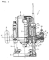
FIG. 1 is a front view of a router according to an exemplary embodiment of the present invention; and -
FIG. 2 is a cross-sectional view of the router taken along line A-A ofFIG. 1 . - Exemplary embodiments of the present invention will be described hereinafter with reference to the accompanying drawings.
- In
FIG. 1 , one example of a router consistent with the present invention is illustrated with a right-side half thereof shown in a vertical section. Referring now toFIGS. 1 and2 , a router 1 comprises a disk-shaped base 2 having an opening at its center, a pair of guide pipes 3 (which serves as a pair of guide shafts) spaced apart laterally and stood upright on an upper surface of thebase 2, and amain body 4 coupled to the bothguide pipes 3 in such a manner that themain body 4 is allowed to be moved upward and downward. Amotor 5 is housed in themain body 4, with its output shaft disposed at a bottom side of the motor, and aspindle 6 coupled to the output shaft projects downwardly from a bottom side of the main body. At a lower end of the spindle 6 a chuck 7 is provided to which a tool (not shown) can be mounted in a detachable manner. Denoted by 8 are handles disposed at both sides of themain body 4. Theright handle 8 includes aswitch 9 and apush button 10. Theswitch 9 is configured to activate themotor 5 in response to the push-in operation of thepush button 10. -
Coupling hollows 11 each of which has an opening facing downward through which acorresponding guide pipe 3 is loosely inserted are formed in themain body 4. A linear ball bearing 12 which serves as a bearing or bushing configured to support thecorresponding guide pipe 3 is provided in a lower portion of each of thecoupling hollows 11. This linear ball bearing 12 comprises: acylindrical retainer 13 held in a corresponding coupling hollow 11, theretainer 13 having a plurality of axially elongated retainingholes 14 formed on an inner cylindrical surface of theretainer 13 and arranged circumferentially at regular intervals; and a plurality ofsteel balls 15 accommodated in each of theretaining holes 14. With the help of this linear ball bearing 12, theguide pipe 3 can be held in the coupling hollow 11 in such a manner that theguide pipe 3 can be slid inside the coupling hollow 11 in an axial direction relative to the coupling hollow 11. - Further, a
guide rod 16, which extends downward and is loosely inserted in thecorresponding guide pipe 3 through an upper opening thereof, is fixed inside the right coupling hollow 11. A coil spring 17 which is wound around theguide rod 16 is disposed inside the coupling hollow 11 and inside theguide pipe 3. Thus, themain body 4 is biased upward by the coil spring 17. A coil spring 17 is similarly disposed inside the left coupling hollow 11 and inside the corresponding guide pipe 3 (second guide pipe as one example of a second tubular guide shaft). However, theguide rod 16 is not provided in the left coupling hollow 11 and instead, a guide bolt (not shown) is disposed coaxially with thesecond guide pipe 3 on thebase 2 inside thesecond guide pipe 3 and extends upward from thebase 2 inside thesecond guide pipe 3 and further inside the main body 4 (left coupling hollow 11). The guide bolt has an upper end portion projecting upward from themain body 4, and athumb nut 18 is screwed on the upper end portion of the guide bolt. Thethumb nut 18 screwed on the upper end portion of the guide bolt is configured to come in contact with an upper surface of themain body 4 when themain body 4 is released and pushed up by the coil spring 17, so as to block an upward movement of themain body 4 - In operation, where the router 1 constructed as described above is used, an operator mounts a tool to the chuck 7, sets the
base 2 on a workpiece, grips thehandles 8 and depresses thepush button 10 to turn on theswitch 9, thereby activating themotor 5 to spin the tool while the operator lowers themain body 4 with thehandles 8 against the biasing force of the coil spring 17. Accordingly, the workpiece under thebase 2 can be cut by means of the tool passing through the center of thebase 2. When the cutting operation is completed and the operator releases his/her hands from thehandles 8, themain body 4 is moved upward by the biasing force of the coil spring 17 to an upper-limit position in which themain body 4 is brought into contact with thethumb nut 18. - During this operation, the upward and downward movement of the
main body 4 can be performed smoothly because the movement is guided by thelinear ball bearings 12 sliding on the outer cylindrical surfaces of theguide pipes 3. Therefore, themain body 4 can be lowered without obstruction even when the operator grips theright handle 8 only, for example. - As described above, in the router 1 according to the present embodiment, the use of a
linear ball bearings 12 as the bushings for theguide pipes 3 in themain body 4 renders themain body 4 smoothly operable even with one hand when it is moved upward and downward. Further, a backlash between theguide pipes 3 and thelinear ball bearings 12 is reduced or eliminated, so that the ease of operation and the cutting precision can be improved. - Although the exemplary embodiment of the present invention has been described above, the present invention is not limited to the illustrated embodiment, and may be carried out into practice in various other ways. Therefore, it is contemplated that various modifications and changes may be made to the exemplary embodiment of the invention without departing from the scope of the embodiments of the present invention as defined in the appended claims.
- For example, in the above embodiment a linear ball bearing is used as the bushing for the both of a pair of guide pipes; however, an alternative embodiment may be configured such that only one of the bushings includes a linear ball bearing and the other bushing is implemented as being of a conventional sleeve-like type or others which are not linear ball bearings. In this embodiment where a linear ball bearing is provided in either one of the bushings, for example, an appropriate adjustment may preferably be made in the interference of a blocking member for press-fitting a retainer into the coupling hollow from below and holding the same in a definite position, to thereby apply a preload to the linear ball bearing. The preload applied to the linear ball bearing may thus serve to suppress a backlash of steel balls of the linear ball bearing, so that the main body can be moved upward and downward more smoothly.
- Although only one unit of the linear ball bearing is provided in each coupling hollow in the above-described embodiment, two or more linear ball bearing units may be arranged in an axial direction of a corresponding guide pipe (guide shaft) which is to be supported by the two or more linear ball bearing units. The increase in the number of the linear ball bearing units may contribute to a smoother and more stable operation of upward and downward movement of the main body.
- Furthermore, the guide shaft may not necessarily be in the form of a hollow cylinder like a guide pipe as illustrated in the present embodiment, but a solid column may be used in the present invention.
- Optionally, a router according to another exemplary embodiment of the present invention may be configured such that horizontal distances between axes of a pair of guide shafts as defined in the base and between axes of a pair of bushings as defined in the main body have a slight difference instead of being identical whereby a preload is horizontally applied to the linear ball bearings included in the bushings by which the guide shafts are supported. In this particular configuration, a backlash between each guide shaft and the linear ball bearing can be suppressed more effectively, and the operation for moving the main body upward and downward can be carried out more smoothly. As a result, the cutting precision can be improved significantly. These advantages may also apply to the embodiments where the linear ball bearing is employed in either one of the bushings.
- It is explicitly stated that all features disclosed in the description and/or the claims are intended to be disclosed separately and independently from each other for the purpose of original disclosure as well as for the purpose of restricting the claimed invention independent of the composition of the features in the embodiments and/or the claims. It is explicitly stated that all value ranges or indications of groups of entities disclose every possible intermediate value or intermediate entity for the purpose of original disclosure as well as for the purpose of restricting the claimed invention, in particular as limits of value ranges.
Claims (10)
- A router, comprising
a base (2),
a pair of guide shafts (3) standing on the base (2), and
a main body (4) coupled to the guide shafts (3) and being adapted to have a tool detachably mounted pointing downward on an underside of the main body (4),
characterized in that the main body (4) comprises a pair of bushings which are configured to support the guide shafts (3), and at least one of the bushings includes a linear ball bearing (12). - The router according to claim 1, wherein only one of the bushings includes the linear ball bearing (12).
- The router according to claim 1, wherein at least one of the bushings includes a plurality of linear ball bearings (12) arranged in an axial direction of a corresponding guide shaft (3) which is to be supported by the plurality of linear ball bearings (12).
- The router according to any one of the claims 1 to 3, wherein a horizontal distance between axes of the pair of guide shafts (3) is different from a horizontal distance between axes of the pair of bushings, whereby a preload is horizontally applied to the linear ball bearing (12) included in at least one of the bushings.
- The router according to any one of the claims 1 to 4, wherein the main body (4) further comprises a pair of coupling hollows (11) each of which has an opening facing downward through which a corresponding guide shaft (3) is inserted, and the linear ball bearing (12) is provided in a lower portion of at least one of the coupling hollows (11).
- The router according to claim 5,
wherein the linear ball bearing (12) comprises
a cylindrical retainer (13) held in at least one of the coupling hollows (11), and a plurality of steel balls (15) accommodated in each of retaining holes (14), and the retainer (13) having a plurality of axially elongated retaining holes (14) formed on an inner cylindrical surface thereof and arranged circumferentially at regular intervals. - The router according to any one of the claims 1 to 6, wherein at least one of the guide shafts (3) is tubular.
- The router according to claim 1, further comprising a coil spring (17), wherein the main body (4) further comprises
a pair of coupling hollows (11) each of which has an opening facing downward through which a corresponding tubular guide shaft (3) is inserted, and
a guide rod (16) fixed inside one of the coupling hollows (11), the guide rod (16) extending downward and being inserted in the tubular guide shaft (3) through an upper opening thereof, and
wherein the coil spring (17) is wound around the guide rod and disposed inside the one of the coupling hollows (11) and inside the tubular guide shaft (3), whereby the main body (4) is biased upward by the coil spring (17). - The router according to claim 8, further comprising
a guide bolt stood in a position on the base (2) inside a second tubular guide shaft (3), the guide bolt having an upper end portion which is threaded, and
a nut (18) configured to be screwable onto the threaded upper end portion of the guide bolt, wherein the other of the coupling hollows (11) has an opening facing upward through which the guide bolt extending from the base (2) inside the second tubular guide shaft (3) and further inside the other of the coupling hollows (11) projects upward, so that the nut (18) screwed on the upper end portion of the guide bolt is brought into contact with an upper surface of the main body (4) to block an upward movement of the main body (4). - The router according to any one of the claims 1 to 9, wherein the main body (4) further comprises handles (8) which are disposed at right and left sides of the main body (4).
Applications Claiming Priority (1)
| Application Number | Priority Date | Filing Date | Title |
|---|---|---|---|
| JP2007285435A JP2009113216A (en) | 2007-11-01 | 2007-11-01 | Router |
Publications (3)
| Publication Number | Publication Date |
|---|---|
| EP2055453A2 true EP2055453A2 (en) | 2009-05-06 |
| EP2055453A3 EP2055453A3 (en) | 2011-05-11 |
| EP2055453B1 EP2055453B1 (en) | 2012-08-29 |
Family
ID=40265982
Family Applications (1)
| Application Number | Title | Priority Date | Filing Date |
|---|---|---|---|
| EP08019135A Active EP2055453B1 (en) | 2007-11-01 | 2008-10-31 | Router |
Country Status (4)
| Country | Link |
|---|---|
| US (1) | US8210780B2 (en) |
| EP (1) | EP2055453B1 (en) |
| JP (1) | JP2009113216A (en) |
| CN (1) | CN101422911B (en) |
Families Citing this family (5)
| Publication number | Priority date | Publication date | Assignee | Title |
|---|---|---|---|---|
| JP5252376B2 (en) * | 2009-01-27 | 2013-07-31 | 日立工機株式会社 | Portable router |
| US8628280B2 (en) | 2009-02-13 | 2014-01-14 | Black & Decker Inc. | Router |
| GB201600883D0 (en) * | 2016-01-18 | 2016-03-02 | Power Box Ag | Improvements to router apparatus |
| US20220388196A1 (en) * | 2019-10-31 | 2022-12-08 | Koki Holdings Co., Ltd. | Router |
| JP1684131S (en) * | 2020-11-13 | 2021-04-26 |
Citations (1)
| Publication number | Priority date | Publication date | Assignee | Title |
|---|---|---|---|---|
| JPH06328402A (en) | 1993-05-18 | 1994-11-29 | Ryobi Motor Prod Corp | Plunge router |
Family Cites Families (14)
| Publication number | Priority date | Publication date | Assignee | Title |
|---|---|---|---|---|
| US3739824A (en) | 1971-11-03 | 1973-06-19 | G Hoenig | Pantograph apparatus |
| DE4139759A1 (en) * | 1991-12-03 | 1993-06-09 | Robert Bosch Gmbh, 7000 Stuttgart, De | UP MILL |
| US5253400A (en) * | 1992-08-24 | 1993-10-19 | Conachen James A | Motorized guide for grouting and sawing window sashes |
| JP3488073B2 (en) * | 1998-01-26 | 2004-01-19 | 株式会社マキタ | Circular saw slide support structure |
| US20010042310A1 (en) | 2000-05-02 | 2001-11-22 | Roland Steele | Flush cut power saw apparatus |
| US6488455B1 (en) | 2000-07-28 | 2002-12-03 | S-B Power Tool Company | Plunge base router |
| DE10051770A1 (en) | 2000-10-19 | 2002-05-02 | Ina Schaeffler Kg | linear bearings |
| US6863480B1 (en) * | 2002-08-06 | 2005-03-08 | Porter-Cable Corporation | Router plunge depth adjustment mechanism |
| US6955508B1 (en) | 2002-11-26 | 2005-10-18 | Radcliffe Gregory P | Apparatus and method for separately boring precisely aligned opposing screw holes in individual frame members to be joined at a miter joint |
| US7337812B2 (en) | 2004-08-13 | 2008-03-04 | Williams Gary E | Multi-function adjustable router base |
| US8047417B2 (en) | 2005-12-06 | 2011-11-01 | Tol-O-Matic, Inc. | Rotatable tool and apparatus therefor |
| DE102006061241A1 (en) | 2006-12-22 | 2008-06-26 | Robert Bosch Gmbh | router |
| DE102006061235B4 (en) | 2006-12-22 | 2019-06-06 | Robert Bosch Gmbh | router |
| DE102006061239A1 (en) | 2006-12-22 | 2008-06-26 | Robert Bosch Gmbh | router |
-
2007
- 2007-11-01 JP JP2007285435A patent/JP2009113216A/en active Pending
-
2008
- 2008-10-28 US US12/289,448 patent/US8210780B2/en active Active
- 2008-10-30 CN CN200810173601.7A patent/CN101422911B/en active Active
- 2008-10-31 EP EP08019135A patent/EP2055453B1/en active Active
Patent Citations (1)
| Publication number | Priority date | Publication date | Assignee | Title |
|---|---|---|---|---|
| JPH06328402A (en) | 1993-05-18 | 1994-11-29 | Ryobi Motor Prod Corp | Plunge router |
Also Published As
| Publication number | Publication date |
|---|---|
| JP2009113216A (en) | 2009-05-28 |
| EP2055453B1 (en) | 2012-08-29 |
| CN101422911B (en) | 2013-06-05 |
| US20090116923A1 (en) | 2009-05-07 |
| EP2055453A3 (en) | 2011-05-11 |
| CN101422911A (en) | 2009-05-06 |
| US8210780B2 (en) | 2012-07-03 |
Similar Documents
| Publication | Publication Date | Title |
|---|---|---|
| US8210780B2 (en) | Router | |
| US6834434B2 (en) | Spring-loaded engraving toolholder | |
| EP3607855B1 (en) | Height-adjustbale table leg | |
| CA2321574A1 (en) | Quick change adjustable punch tool assembly and method of adjustment | |
| US7524151B2 (en) | Power tool with cutting depth adjustment mechanism | |
| US20040228698A1 (en) | Cemented carbide broach and broaching machine | |
| CN101204744B (en) | Router with bearing arrangement | |
| US8915172B1 (en) | Magnetized fence with integral stock feeder for decked saws | |
| CN102177001B (en) | Feed guide unit for linear guidance of hand-held power tools | |
| GB2383555A (en) | Retractable rod-like device of non-circular cross-section | |
| EP2392427B1 (en) | Width adjustable worktable | |
| US5482416A (en) | Metal working machine | |
| GB2445253A (en) | Router with depth adjustment means in dome of housing | |
| GB2445257A (en) | Router with device for indicating position of housing | |
| US20080271664A1 (en) | Feedback Systems for Adjustment Mechanisms on Power Tools | |
| WO2002058870A1 (en) | Holder and chuck device | |
| JP2003278873A (en) | Linear motion equipment | |
| US8375835B2 (en) | Guide bar track extension method and apparatus | |
| EP3192624B1 (en) | Power tool | |
| US20210387293A1 (en) | Fixture for laser engraving long heavy objects | |
| GB2448789A (en) | Cradle support for a machine tool | |
| ATE229409T1 (en) | HANDLING DEVICE | |
| KR200489762Y1 (en) | Apparatus for supporting drill | |
| DE102011082263A1 (en) | Device for fine adjustment of portable machine tool e.g. router, has operation knob that is supported relative to housing unit, so that knob is movable along a direction different from direction of rotation axis of knob | |
| KR101521789B1 (en) | Gear vise using a worm gear |
Legal Events
| Date | Code | Title | Description |
|---|---|---|---|
| PUAI | Public reference made under article 153(3) epc to a published international application that has entered the european phase |
Free format text: ORIGINAL CODE: 0009012 |
|
| AK | Designated contracting states |
Kind code of ref document: A2 Designated state(s): AT BE BG CH CY CZ DE DK EE ES FI FR GB GR HR HU IE IS IT LI LT LU LV MC MT NL NO PL PT RO SE SI SK TR |
|
| AX | Request for extension of the european patent |
Extension state: AL BA MK RS |
|
| PUAL | Search report despatched |
Free format text: ORIGINAL CODE: 0009013 |
|
| AK | Designated contracting states |
Kind code of ref document: A3 Designated state(s): AT BE BG CH CY CZ DE DK EE ES FI FR GB GR HR HU IE IS IT LI LT LU LV MC MT NL NO PL PT RO SE SI SK TR |
|
| AX | Request for extension of the european patent |
Extension state: AL BA MK RS |
|
| 17P | Request for examination filed |
Effective date: 20111109 |
|
| AKX | Designation fees paid |
Designated state(s): DE FR GB |
|
| GRAP | Despatch of communication of intention to grant a patent |
Free format text: ORIGINAL CODE: EPIDOSNIGR1 |
|
| GRAS | Grant fee paid |
Free format text: ORIGINAL CODE: EPIDOSNIGR3 |
|
| GRAA | (expected) grant |
Free format text: ORIGINAL CODE: 0009210 |
|
| AK | Designated contracting states |
Kind code of ref document: B1 Designated state(s): DE FR GB |
|
| REG | Reference to a national code |
Ref country code: GB Ref legal event code: FG4D |
|
| REG | Reference to a national code |
Ref country code: DE Ref legal event code: R096 Ref document number: 602008018315 Country of ref document: DE Effective date: 20121025 |
|
| PLBE | No opposition filed within time limit |
Free format text: ORIGINAL CODE: 0009261 |
|
| STAA | Information on the status of an ep patent application or granted ep patent |
Free format text: STATUS: NO OPPOSITION FILED WITHIN TIME LIMIT |
|
| 26N | No opposition filed |
Effective date: 20130530 |
|
| REG | Reference to a national code |
Ref country code: DE Ref legal event code: R097 Ref document number: 602008018315 Country of ref document: DE Effective date: 20130530 |
|
| REG | Reference to a national code |
Ref country code: FR Ref legal event code: PLFP Year of fee payment: 9 |
|
| REG | Reference to a national code |
Ref country code: FR Ref legal event code: PLFP Year of fee payment: 10 |
|
| REG | Reference to a national code |
Ref country code: FR Ref legal event code: PLFP Year of fee payment: 11 |
|
| PGFP | Annual fee paid to national office [announced via postgrant information from national office to epo] |
Ref country code: GB Payment date: 20250911 Year of fee payment: 18 |
|
| PGFP | Annual fee paid to national office [announced via postgrant information from national office to epo] |
Ref country code: FR Payment date: 20250908 Year of fee payment: 18 |
|
| PGFP | Annual fee paid to national office [announced via postgrant information from national office to epo] |
Ref country code: DE Payment date: 20250902 Year of fee payment: 18 |