EP2055170B1 - Four-bar linkage for suspending a header for an agricultural implement - Google Patents
Four-bar linkage for suspending a header for an agricultural implement Download PDFInfo
- Publication number
- EP2055170B1 EP2055170B1 EP08153232.7A EP08153232A EP2055170B1 EP 2055170 B1 EP2055170 B1 EP 2055170B1 EP 08153232 A EP08153232 A EP 08153232A EP 2055170 B1 EP2055170 B1 EP 2055170B1
- Authority
- EP
- European Patent Office
- Prior art keywords
- link
- frame
- sub
- upper link
- lower link
- Prior art date
- Legal status (The legal status is an assumption and is not a legal conclusion. Google has not performed a legal analysis and makes no representation as to the accuracy of the status listed.)
- Ceased
Links
- 238000000034 method Methods 0.000 claims description 14
- 230000006835 compression Effects 0.000 claims description 4
- 238000007906 compression Methods 0.000 claims description 4
- 239000000725 suspension Substances 0.000 description 10
- 230000008901 benefit Effects 0.000 description 5
- 238000009825 accumulation Methods 0.000 description 1
- 230000003247 decreasing effect Effects 0.000 description 1
- 239000004459 forage Substances 0.000 description 1
- 239000000463 material Substances 0.000 description 1
- 238000012986 modification Methods 0.000 description 1
- 230000004048 modification Effects 0.000 description 1
Images








Classifications
-
- A—HUMAN NECESSITIES
- A01—AGRICULTURE; FORESTRY; ANIMAL HUSBANDRY; HUNTING; TRAPPING; FISHING
- A01D—HARVESTING; MOWING
- A01D34/00—Mowers; Mowing apparatus of harvesters
- A01D34/01—Mowers; Mowing apparatus of harvesters characterised by features relating to the type of cutting apparatus
- A01D34/412—Mowers; Mowing apparatus of harvesters characterised by features relating to the type of cutting apparatus having rotating cutters
- A01D34/63—Mowers; Mowing apparatus of harvesters characterised by features relating to the type of cutting apparatus having rotating cutters having cutters rotating about a vertical axis
- A01D34/64—Mowers; Mowing apparatus of harvesters characterised by features relating to the type of cutting apparatus having rotating cutters having cutters rotating about a vertical axis mounted on a vehicle, e.g. a tractor, or drawn by an animal or a vehicle
- A01D34/66—Mowers; Mowing apparatus of harvesters characterised by features relating to the type of cutting apparatus having rotating cutters having cutters rotating about a vertical axis mounted on a vehicle, e.g. a tractor, or drawn by an animal or a vehicle with two or more cutters
- A01D34/661—Mounting means
-
- Y—GENERAL TAGGING OF NEW TECHNOLOGICAL DEVELOPMENTS; GENERAL TAGGING OF CROSS-SECTIONAL TECHNOLOGIES SPANNING OVER SEVERAL SECTIONS OF THE IPC; TECHNICAL SUBJECTS COVERED BY FORMER USPC CROSS-REFERENCE ART COLLECTIONS [XRACs] AND DIGESTS
- Y10—TECHNICAL SUBJECTS COVERED BY FORMER USPC
- Y10T—TECHNICAL SUBJECTS COVERED BY FORMER US CLASSIFICATION
- Y10T29/00—Metal working
- Y10T29/49—Method of mechanical manufacture
- Y10T29/49826—Assembling or joining
Definitions
- the present invention relates generally to an agricultural implement, including a floating work tool. More particularly, the present invention relates to an improved suspension system for agricultural implements having one or more floating work tools.
- Ground on which forage crops or other foliage needing mowing is grown is rarely smooth. Such ground essentially always varies in level both in a direction of travel of the mowing machine or harvester, and in a transverse or lateral direction.
- Mowing machines having a variable height cutter have been available for decades. Mounted sickle mowers used in the mid-twentieth century could be raised and lowered using the tractor lift system. Towed mowers, by necessity, were made so the header could be raised and lowered, at least between an operating position and a transport position.
- a mower header suspension system is disclosed.
- the suspension system comprises a pair of lower linkage arms and a single upper suspension arm. Provision for changes in ground elevation in the direction of travel is disclosed.
- U.S. Patent No. 6,055,800 Disclosed in U.S. Patent No. 6,055,800 is a mower header suspension system providing a variable header angle compared to the longitudinal direction.
- the disclosed mechanism comprises two lower linkage arms and a single upper linkage arms.
- the above described header suspension systems provide for changing the height of cut relative to the ground surface supporting the ground engaging wheels of the tractor or towed mower, but do not provide for a consistent cut height on ground that varies in level both in the direction of travel and in the lateral direction.
- U.S. Patent No. 5,060,462 discloses a towable implement having the precharacterising features of claim 1.
- a towable implement comprising a main frame, a sub-frame, a header and a four-bar linkage system comprising an upper link and a lower link, in which implement, so that the header may be permitted to float:
- the implement could be such that the lower link comprises a first lower link and the upper link comprises a first upper link, the towed implement additionally comprising a second lower link and a second upper link, wherein:
- the second end of the first upper link could be operatively rigidly attached to the second end of the second upper link.
- the first end of the first lower link could be disposed nearer the first end of the second lower link than the second end of the first lower link to the second end of the second lower link; and/or the second end of the first upper link could be disposed nearer the second end of the second upper link than the first end of the first upper link to the first end of the second upper link.
- the second end of the first lower link could be disposed nearer the second end of the second lower link than the first end of the first lower link to the first end of the second lower link; and/or the first end of the first upper link could be disposed nearer the first end of the second upper link than the second end of the first upper link to the second end of the second upper link.
- a method of suspending a header from a towed implement to permit the header to float comprising:
- the following embodiments provide a suspension system that enables a header or work tool of a towed implement to be raised and lowered, and also permit the header or work tool to follow the variable ground contour, resulting in a consistent cut height despite the variability of the ground elevation.
- a towed implement is an implement with ground engaging means, for example wheels, independent of the source of motive power, for example a farm tractor; additionally, the towed implement has a frame or other component that may be raised and lowered relative to the ground engaging means independent of a lift, such as a standard three-point or two-point lift system of the source of motive power. Therefore, a towed vehicle is pulled by the source of motive power and my use the source of motive power's hydraulic system for raising and lowering, but does not make use of lift arms usually attached to a farm tractor.
- the mower comprises two integrated frames connected by two sets of linkages to create a four-bar linkage.
- the two sets of linkages are maintained parallel to one another, so that the two frames are maintained at a known orientation to one another as the header is raised and lowered.
- the upper linkage set comprises two "bars,” oriented at angles with respect to a longitudinal axis of the mower such that they connect to the sub-frame at points nearer the longitudinal axis than those points at which they connect to the main frame.
- the lower links are angled such that they connect to the sub-frame at points farther from the longitudinal axis than those points at which the lower links connect to the main frame.
- Spherical bearings are used to connect each independent bar of the lower linkage set to the main frame and to the sub-frame. As well, spherical bearings are also used to connect the upper linkage bars to the sub-frame. The upper linkage bars are pivotally attached to the main frame by cylindrical bearings.
- the upper linkage bars are permanently connected to one another where the upper linkage bars converge at the sub-frame, and are subsequently connected to the sub-frame using a single spherical bearing.
- the two bars are not directly connected to one another, but are pivotally connected to the sub-frame by independent spherical bearings in the same manner as the lower linkage bars.
- the linkage arrangement herein described allows the sub-frame the ability to rotate about an axis of rotation parallel to the longitudinal axis of the mower. This ability is called “float” and refers to the capability of the mower to adjust itself automatically to a ground slope perpendicular to the direction of travel.
- the present invention comprises a suspension system for an agricultural mower 1, shown in its entirety in Figs. 1a , 1b , 6a , and 6b .
- the mower 1 comprises two integrated frames 10, 15.
- a tongue 2 extending over the machine is pivotally connected to a top of a main frame 15, positioned at the extreme rear of the agricultural mower 1.
- the main frame 15 has left and right legs mounted atop axles between two ground engaging wheels for supporting the agricultural mower 1 on the ground 65. The axis of rotation of these wheels is substantially perpendicular to a direction of travel.
- a sub-frame 10 is pivotally connected to the main frame 15, forward of the main frame 15 by means of a four-bar linkage system.
- the sub-frame 10 is a two part frame, suspending the work tool or cutter bar 9.
- the tongue 2 is preferably connected to an agricultural tractor (not shown).
- the mower 1 is normally drawn in a direction toward the tongue 2, which direction is hereby defined as the forward direction. Based on this, the rearward direction is hereby defined for the purposes of this document, including the claims as opposite the forward direction.
- a front of the mower 1 is likewise hereby defined as the general portion of the mower 1 in the lead as the mower 1 is drawn in the forward direction.
- a rear of the mower 1 is hereby defined as the general portion of the mower 1 seen when viewed from a side of the mower 1 opposite the tongue and facing in the forward direction.
- a longitudinal direction is hereby defined as a direction parallel to the forward direction.
- a transverse direction is hereby defined as a direction perpendicular to the longitudinal direction, and parallel to an appropriate average of a slope of the ground surface in the vicinity of a header 6.
- the present invention comprises a four-bar linkage system including an upper set of linkages 12 and a lower set of linkages 11, each comprising two bars as illustrated in Figs. 2-4 and 7-10.
- the upper linkage set 12 and the lower linkage set 11 are substantially parallel to one another when considering a side elevation view such as those featured in Figs. 1a and 1b .
- the bars belonging to the upper linkage set 12 are oriented in such a way as to be angled with respect to a longitudinal axis 52 of the mower 1.
- the upper links 12 are angled such that they connect to the sub-frame 10 at points nearer the longitudinal axis 52 than those points at which the upper links 12 connect to the main frame 15.
- the lower links 11 are angled such that they connect to the sub-frame 10 at points farther from the longitudinal axis 52 than those points at which the lower links 11 connect to the main frame 15.
- Each independent bar of the lower linkage set 11 is pivotally connected to the main frame 15 by a spherical bearing, also known as a ball joint, at a first point and is pivotally connected to the sub-frame 10 by a spherical bearing, also known as a ball joint, at a second point.
- a spherical bearing also known as a ball joint
- each bar of the upper linkage 12 is pivotally connected to the main frame 15 by a cylindrical bearing at a first point and pivotally connected to the sub-frame 10 by a spherical bearing, also known as a ball joint, at a second point.
- the upper linkage bars 12 are rigidly affixed to one another where the upper linkage bars 12 converge at the sub-frame 10, and are connected to the sub-frame 10 with a single spherical bearing, as shown in Fig. 7 .
- a second embodiment illustrated in Fig.
- the two bars upper linkage bars 12 are not directly connected to one another, but are pivotally connected to the sub-frame 10 by independent spherical bearings in the same manner as the lower linkage bars 11.
- the ends of the upper linkage bars 12 nearest the sub-frame 10 are disposed closer together than their ends nearest the main frame 15.
- the lower linkage bars 11 diverge from one another as they extend from the main frame 15 to the sub-frame 10.
- the lower link arms 11 are rigidly affixed to one another where the lower linkage bars 11 converge at the sub-frame 10, and are connected to the sub-frame 10 with a single spherical bearing, as shown in Fig. 9 .
- the two lower linkage bars 11 are not directly connected to one another, but are pivotally connected to the sub-frame 10 by independent spherical bearings in the same manner as the upper linkage bars 12.
- the ends of the lower linkage bars 11 nearest the sub-frame 10 are disposed closer together than their ends nearest the main frame 15.
- the upper linkage bars 12 diverge from one another as they extend from the main frame 15 to the sub-frame 10.
- the linkage arrangement described above allows the sub-frame 10 to rotate about an axis of rotation parallel to the longitudinal axis 52.
- This ability is hereby defined as float for the purposed of this document, including the claims, and implies the capability of the mower 1 to adjust itself automatically to a ground slope perpendicular to the direction of travel.
- the two independent headers 6 are supported independently by their respective arms 8 on cylindrical bearings, allowing each cutter bar 9 to float independently. Therefore, the undersides of the cutter bars 9 engage the ground surface 65 with greater consistency due to their floating ability.
- the two arms 8, pivotally mounted to the top of the forward portion of the sub-frame 10, have a vertical axis of rotation.
- the cutter bars 9 mounted from these arms 8 are then allowed to pivot toward or away from the longitudinal axis 52.
- the arms 8 are rotated forward, thereby decreasing a width of the mower 1.
- the arms 8 are rotated toward the rear of the mower 1 such that the two separate cutter bars 9 form a single row perpendicular to the direction of travel.
- the sub-frame lift cylinder 14 is used to raise the sub-frame 10 off the ground 65 for transport.
- the sub-frame 10 is provided with a locking arrangement for the transport position to eliminate the risk of the sub-frame 10 dropping to the ground 65 during transport.
- the present invention realizes significant benefit in that the suspension system mounts the sub-frame 10 in such a way as to give the sub-frame 10 multi-directional motion freedoms such that the underside of the cutter bar 9 is allowed to more consistently engage the ground surface 65 as the ground surface 65 varies. This results in the benefit of a more consistent cut height.
- FIGs. 11a-12b An additional leveling feature is illustrated in Figs. 11a-12b .
- the header As the header is raised from the operating position ( Figs. 11a and 11b ), to the transport position ( Figs. 12a and 12b ), and the upper linkage bars 12 reach an extreme raised position, they make contact with a leveling bracket 75, causing the sub-frame 10, 62 to become parallel to the ground contour in the transverse direction.
- a benefit is that if one side of the header becomes heavy due to accumulation of crop material, etc., it will still become level. This also keeps the sub-frame 10 from swaying while the agricultural mower 1 is in its transport position.
- inventions of the novel suspension system herein described may be utilized for any implement making use of a floating work tool.
- the invention is not intended to be limited to agricultural mowers.
Landscapes
- Life Sciences & Earth Sciences (AREA)
- Environmental Sciences (AREA)
- Harvester Elements (AREA)
- Agricultural Machines (AREA)
Description
- The present invention relates generally to an agricultural implement, including a floating work tool. More particularly, the present invention relates to an improved suspension system for agricultural implements having one or more floating work tools.
- Ground on which forage crops or other foliage needing mowing is grown is rarely smooth. Such ground essentially always varies in level both in a direction of travel of the mowing machine or harvester, and in a transverse or lateral direction.
- Mowing machines having a variable height cutter have been available for decades. Mounted sickle mowers used in the mid-twentieth century could be raised and lowered using the tractor lift system. Towed mowers, by necessity, were made so the header could be raised and lowered, at least between an operating position and a transport position.
- In
U.S. Patent No. 6,250,055 , a mower header suspension system is disclosed. The suspension system comprises a pair of lower linkage arms and a single upper suspension arm. Provision for changes in ground elevation in the direction of travel is disclosed. - Disclosed in
U.S. Patent No. 6,055,800 is a mower header suspension system providing a variable header angle compared to the longitudinal direction. The disclosed mechanism comprises two lower linkage arms and a single upper linkage arms. - The above described header suspension systems provide for changing the height of cut relative to the ground surface supporting the ground engaging wheels of the tractor or towed mower, but do not provide for a consistent cut height on ground that varies in level both in the direction of travel and in the lateral direction.
- There is, therefore, a need for a method and apparatus for providing flexibility in header position to permit the header to raise and lower as ground elevation changes, and to rotate to adjust to lateral variations in ground surface levels.
-
U.S. Patent No. 5,060,462 discloses a towable implement having the precharacterising features ofclaim 1. - According to the present invention from one aspect, there is provided a towable implement, the implement comprising a main frame, a sub-frame, a header and a four-bar linkage system comprising an upper link and a lower link, in which implement, so that the header may be permitted to float:
- (a) a first end of the lower link is operatively pivotally attached to the main frame of the towed implement via a first spherical bearing;
- (b) a second end of the lower link is operatively pivotally attached to the sub-frame via a second spherical bearing;
- (c) a first end of the upper link is operatively pivotally attached to the main frame via a first cylindrical bearing;
- (d) a second end of the upper link is operatively pivotally attached to the sub-frame via a third spherical bearing; and
- (e) the header of the towed implement is operatively attached to the sub-frame, characterized in that:
- (f) an actuator is operatively pivotally affixed to the sub-frame above the upper link;
- (g) the actuator can apply a force to the sub-frame in a direction toward the main frame;
- (h) the upper link is placeable in compression due to the force;
- (i) the lower link is placeable in tension due to the force;
- (j) the sub-frame is raisable due to the force; and
- (k) the sub-frame can self-level due to such tension in the lower link.
- The implement could be such that the lower link comprises a first lower link and the upper link comprises a first upper link, the towed implement additionally comprising a second lower link and a second upper link, wherein:
- (a) a first end of the second lower link is operatively pivotally attached to the main frame of the towed implement via a fourth spherical bearing;
- (b) a second end of the second lower link is operatively pivotally attached to the sub-frame via a fifth spherical bearing;
- (c) a first end of the second upper link is operatively pivotally attached to the main frame via a second cylindrical bearing; and
- (d) a second end of the second upper link is operatively pivotally attached to the sub-frame via a sixth spherical bearing.
- The second end of the first upper link could be operatively rigidly attached to the second end of the second upper link. The first end of the first lower link could be disposed nearer the first end of the second lower link than the second end of the first lower link to the second end of the second lower link; and/or the second end of the first upper link could be disposed nearer the second end of the second upper link than the first end of the first upper link to the first end of the second upper link. The second end of the first lower link could be disposed nearer the second end of the second lower link than the first end of the first lower link to the first end of the second lower link; and/or the first end of the first upper link could be disposed nearer the first end of the second upper link than the second end of the first upper link to the second end of the second upper link.
- According to the present invention from another aspect, there is provided a method of suspending a header from a towed implement to permit the header to float, the towed implement comprising a main frame, a sub-frame, and a four-bar linkage system comprising an upper link and a lower link, the method comprising:
- (a) operatively pivotally attaching a first end of the lower link to the main frame of the towed implement using a first spherical bearing;
- (b) operatively pivotally attaching a second end of the lower link to the sub-frame using a second spherical bearing;
- (c) operatively pivotally attaching a first end of the upper link to the main frame using a first cylindrical bearing;
- (d) operatively pivotally attaching a second end of the upper link to the sub-frame using a third spherical bearing; and
- (e) operatively attaching the header of the towed implement to the sub-frame, characterized in that the method additionally comprises:
- (f) operatively pivotally affixing an actuator to the sub-frame above the upper link;
- (g) applying a force to the sub frame with the actuator in a direction toward the main frame;
- (h) placing the upper link in compression due to the force;
- (i) placing the lower link in tension due to the force;
- (j) raising the sub-frame due to the force; and
- (k) permitting the sub-frame to self-level due to the tension in the lower link.
- The following embodiments provide a suspension system that enables a header or work tool of a towed implement to be raised and lowered, and also permit the header or work tool to follow the variable ground contour, resulting in a consistent cut height despite the variability of the ground elevation.
- For the purposes of this document, including the claims, a towed implement is an implement with ground engaging means, for example wheels, independent of the source of motive power, for example a farm tractor; additionally, the towed implement has a frame or other component that may be raised and lowered relative to the ground engaging means independent of a lift, such as a standard three-point or two-point lift system of the source of motive power. Therefore, a towed vehicle is pulled by the source of motive power and my use the source of motive power's hydraulic system for raising and lowering, but does not make use of lift arms usually attached to a farm tractor.
- The mower comprises two integrated frames connected by two sets of linkages to create a four-bar linkage. The two sets of linkages are maintained parallel to one another, so that the two frames are maintained at a known orientation to one another as the header is raised and lowered.
- The upper linkage set comprises two "bars," oriented at angles with respect to a longitudinal axis of the mower such that they connect to the sub-frame at points nearer the longitudinal axis than those points at which they connect to the main frame.
- In contrast, the lower links are angled such that they connect to the sub-frame at points farther from the longitudinal axis than those points at which the lower links connect to the main frame.
- Spherical bearings are used to connect each independent bar of the lower linkage set to the main frame and to the sub-frame. As well, spherical bearings are also used to connect the upper linkage bars to the sub-frame. The upper linkage bars are pivotally attached to the main frame by cylindrical bearings.
- In a first embodiment, the upper linkage bars are permanently connected to one another where the upper linkage bars converge at the sub-frame, and are subsequently connected to the sub-frame using a single spherical bearing. In an alternative embodiment, the two bars are not directly connected to one another, but are pivotally connected to the sub-frame by independent spherical bearings in the same manner as the lower linkage bars.
- The linkage arrangement herein described allows the sub-frame the ability to rotate about an axis of rotation parallel to the longitudinal axis of the mower. This ability is called "float" and refers to the capability of the mower to adjust itself automatically to a ground slope perpendicular to the direction of travel.
- Other objects, advantages and novel features of the present invention will become apparent from the following detailed description of the invention when considered in conjunction with the accompanying drawings.
-
-
Fig. 1a is a side elevation of a mower machine in a transport configuration; -
Fig. 1b is a side elevation of the mower machine in an operating configuration; -
Fig. 2 is a rear elevation view of the mower showing a four-bar linkage system arrangement; -
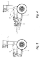
Fig. 3 is a left side elevation view of the rear of the mower showing the main frame mounted on wheels and indicating the parallelism of the two linkage levels; -
Fig. 4 is a left side elevation view of the rear of the mower showing the pivot point in the sub-frame about which the cutter bar pitch is controlled; -
Fig. 5a is a top plan view of the sub-frame in a transport configuration showing both arms rotated inward toward the longitudinal axis; -
Fig. 5b is a top plan view of the sub-frame in an operating configuration showing botharms 8 rotated outward from the longitudinal axis; -
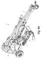
Fig. 6a is an isometric view of the mower in transport configuration; -
Fig. 6b is an isometric view of the mower in operational configuration; -
Fig. 7 is a rear elevation view of the mower in a first embodiment of the present invention; -
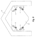
Fig. 8 is a rear elevation view of the mower in a second embodiment having individual links at a top of the four-bar linkage system; -
Fig. 9 is a rear elevation view of the mower presenting a third embodiment of the four-bar linkage system in which the orientations of the upper and lower linkage sets are opposite of those in the first embodiment; -
Fig. 10 is a rear elevation view of the mower presenting a fourth embodiment of the four-bar linkage system in which the orientations of the upper and lower linkage sets are opposite of those in the second embodiment; -
Fig. 11a is a top plan view of the mower with its header in an operating position illustrating a leveling mechanism; -
Fig. 11b is a side elevation view of the mower with its header in an operating position illustrating the leveling mechanism; -
Fig. 12a is a top plan view of the mower with its header in a transport position illustrating the leveling mechanism; and -
Fig. 12b is a side elevation view of the mower with its header in a transport position illustrating the leveling mechanism. - Referring now to the drawings wherein like reference numerals indicate identical or corresponding parts throughout the several views, the present invention comprises a suspension system for an
agricultural mower 1, shown in its entirety inFigs. 1a ,1b ,6a , and6b . Themower 1 comprises twointegrated frames tongue 2 extending over the machine is pivotally connected to a top of amain frame 15, positioned at the extreme rear of theagricultural mower 1. Themain frame 15 has left and right legs mounted atop axles between two ground engaging wheels for supporting theagricultural mower 1 on theground 65. The axis of rotation of these wheels is substantially perpendicular to a direction of travel. Asub-frame 10 is pivotally connected to themain frame 15, forward of themain frame 15 by means of a four-bar linkage system. Thesub-frame 10 is a two part frame, suspending the work tool orcutter bar 9. - The
tongue 2 is preferably connected to an agricultural tractor (not shown). Themower 1 is normally drawn in a direction toward thetongue 2, which direction is hereby defined as the forward direction. Based on this, the rearward direction is hereby defined for the purposes of this document, including the claims as opposite the forward direction. - A front of the
mower 1 is likewise hereby defined as the general portion of themower 1 in the lead as themower 1 is drawn in the forward direction. A rear of themower 1 is hereby defined as the general portion of themower 1 seen when viewed from a side of themower 1 opposite the tongue and facing in the forward direction. - A longitudinal direction is hereby defined as a direction parallel to the forward direction. A transverse direction is hereby defined as a direction perpendicular to the longitudinal direction, and parallel to an appropriate average of a slope of the ground surface in the vicinity of a header 6.
- The above definitions are defined for the purposes of this document, including the claims.
- The present invention comprises a four-bar linkage system including an upper set of
linkages 12 and a lower set oflinkages 11, each comprising two bars as illustrated inFigs. 2-4 and 7-10. The upper linkage set 12 and the lower linkage set 11 are substantially parallel to one another when considering a side elevation view such as those featured inFigs. 1a and1b . As shown in the plan views ofFigs. 5a and5b , and the rear elevation view,Fig. 7 , the bars belonging to the upper linkage set 12 are oriented in such a way as to be angled with respect to alongitudinal axis 52 of themower 1. More precisely, theupper links 12 are angled such that they connect to thesub-frame 10 at points nearer thelongitudinal axis 52 than those points at which theupper links 12 connect to themain frame 15. Thelower links 11 are angled such that they connect to thesub-frame 10 at points farther from thelongitudinal axis 52 than those points at which thelower links 11 connect to themain frame 15. - Each independent bar of the lower linkage set 11 is pivotally connected to the
main frame 15 by a spherical bearing, also known as a ball joint, at a first point and is pivotally connected to thesub-frame 10 by a spherical bearing, also known as a ball joint, at a second point. - As illustrated in
Figs. 7-10 , each bar of theupper linkage 12 is pivotally connected to themain frame 15 by a cylindrical bearing at a first point and pivotally connected to thesub-frame 10 by a spherical bearing, also known as a ball joint, at a second point. In a first embodiment, the upper linkage bars 12 are rigidly affixed to one another where the upper linkage bars 12 converge at thesub-frame 10, and are connected to thesub-frame 10 with a single spherical bearing, as shown inFig. 7 . In a second embodiment, illustrated inFig. 8 , the two bars upper linkage bars 12 are not directly connected to one another, but are pivotally connected to thesub-frame 10 by independent spherical bearings in the same manner as the lower linkage bars 11. In this second embodiment, the ends of the upper linkage bars 12 nearest thesub-frame 10 are disposed closer together than their ends nearest themain frame 15. In either of the first and second embodiment, the lower linkage bars 11 diverge from one another as they extend from themain frame 15 to thesub-frame 10. - In a third embodiment, the
lower link arms 11 are rigidly affixed to one another where the lower linkage bars 11 converge at thesub-frame 10, and are connected to thesub-frame 10 with a single spherical bearing, as shown inFig. 9 . In a fourth embodiment, illustrated inFig. 10 , the two lower linkage bars 11 are not directly connected to one another, but are pivotally connected to thesub-frame 10 by independent spherical bearings in the same manner as the upper linkage bars 12. In this fourth embodiment, the ends of the lower linkage bars 11 nearest thesub-frame 10 are disposed closer together than their ends nearest themain frame 15. In either of the first and second embodiment, the upper linkage bars 12 diverge from one another as they extend from themain frame 15 to thesub-frame 10. - The linkage arrangement described above allows the
sub-frame 10 to rotate about an axis of rotation parallel to thelongitudinal axis 52. This ability is hereby defined as float for the purposed of this document, including the claims, and implies the capability of themower 1 to adjust itself automatically to a ground slope perpendicular to the direction of travel. As illustrated especially inFigs. 5a ,5b ,6a , and6b , the two independent headers 6 are supported independently by theirrespective arms 8 on cylindrical bearings, allowing eachcutter bar 9 to float independently. Therefore, the undersides of the cutter bars 9 engage theground surface 65 with greater consistency due to their floating ability. - The two
arms 8, pivotally mounted to the top of the forward portion of thesub-frame 10, have a vertical axis of rotation. The cutter bars 9 mounted from thesearms 8 are then allowed to pivot toward or away from thelongitudinal axis 52. As shown inFigs. 1a ,5a , and6a , in a transport position, thearms 8 are rotated forward, thereby decreasing a width of themower 1. In an operating mode, illustrated inFigs. 1b ,5b and6b , thearms 8 are rotated toward the rear of themower 1 such that the twoseparate cutter bars 9 form a single row perpendicular to the direction of travel. Thesub-frame lift cylinder 14 is used to raise thesub-frame 10 off theground 65 for transport. Thesub-frame 10 is provided with a locking arrangement for the transport position to eliminate the risk of thesub-frame 10 dropping to theground 65 during transport. - The present invention realizes significant benefit in that the suspension system mounts the
sub-frame 10 in such a way as to give thesub-frame 10 multi-directional motion freedoms such that the underside of thecutter bar 9 is allowed to more consistently engage theground surface 65 as theground surface 65 varies. This results in the benefit of a more consistent cut height. - Another significant benefit is realized by the converging and diverging arrangements of the lower linkage bars 11 and the upper linkage bars 12, in combination with the illustrated orientation
sub-frame lift cylinder 14. Due to the lower linkage bars 11 being in tension whenever thesub-frame lift cylinder 14 is retracted, the header 6 is self-leveling when in the transport position, while the header 6 is permitted to be parallel to the ground when in the operating position. Further, due to the tension in the lower linkage bars 11, the header will tend to center itself relative to themain frame 15 on retraction of thesub-frame lift cylinder 14. - An additional leveling feature is illustrated in
Figs. 11a-12b . As the header is raised from the operating position (Figs. 11a and 11b ), to the transport position (Figs. 12a and 12b ), and the upper linkage bars 12 reach an extreme raised position, they make contact with a levelingbracket 75, causing thesub-frame agricultural mower 1 is in its transport position. - The embodiments of the novel suspension system herein described may be utilized for any implement making use of a floating work tool. The invention is not intended to be limited to agricultural mowers.
- The above embodiments are the preferred embodiments, but this invention is not limited thereto. It is, therefore, apparent that many modifications and variations of the present invention are possible in light of the above teachings. It is, therefore, to be understood that within the scope of the appended claims, the invention may be practiced otherwise than as specifically described.
Claims (14)
- A towable implement (1), the implement comprising a main frame (15), a sub-frame (10), a header (6) and a four-bar linkage system comprising an upper link (12) and a lower link (11), in which implement, so that the header may be permitted to float:(a) a first end of the lower link is operatively pivotally attached to the main frame of the towed implement via a first spherical bearing;(b) a second end of the lower link is operatively pivotally attached to the sub-frame via a second spherical bearing;(c) a first end of the upper link is operatively pivotally attached to the main frame via a first cylindrical bearing;(d) a second end of the upper link is operatively pivotally attached to the sub-frame via a third spherical bearing; and(e) the header of the towed implement is operatively attached to the sub-frame, characterized in that:(f) an actuator (14) is operatively pivotally affixed to the sub-frame above the upper link;(g) the actuator can apply a force to the sub-frame in a direction toward the main frame;(h) the upper link is placeable in compression due to the force;(i) the lower link is placeable in tension due to the force;(j) the sub-frame is raisable due to the force; and(k) the sub-frame can self-level due to such tension in the lower link.
- An implement (1) according to claim 1, wherein the lower link comprises a first lower link (11) and the upper link comprises a first upper link (12) and the implement additionally comprises a second lower link (11) and a second upper link (12), wherein:(a) a first end of the second lower link is operatively pivotally attached to the main frame (15) of the towed implement via a fourth spherical bearing;(b) a second end of the second lower link is operatively pivotally attached to the sub-frame (10) via a fifth spherical bearing;(c) a first end of the second upper link is operatively pivotally attached to the main frame via a second cylindrical bearing; and(d) a second end of the second upper link is operatively pivotally attached to the sub-frame via a sixth spherical bearing.
- An implement (1) according to claim 2, wherein the second end of the first upper link (12) is operatively rigidly attached to the second end of the second upper link (12).
- An implement (1) according to claim 2 or 3, wherein the first end of the first lower link (11) is disposed nearer the first end of the second lower link (11) than the second end of the first lower link to the second end of the second lower link.
- An implement (1) according to any of claims 2 to 4, wherein the second end of the first upper link (12) is disposed nearer the second end of the second upper link (12) than the first end of the first upper link to the first end of the second upper link.
- An implement (1) according to claim 2 or 3, wherein the second end of the first lower link (11) is disposed nearer the second end of the second lower link (11) than the first end of the first lower link to the first end of the second lower link.
- An implement (1) according to any of claims 2, 3 and 6, wherein the first end of the first upper link (12) is disposed nearer the first end of the second upper link (12) than the second end of the first upper link to the second end of the second upper link.
- A method of suspending a header (6) from a towed implement (1) to permit the header to float, the towed implement comprising a main frame (15), a sub-frame (10), and a four-bar linkage system comprising an upper link (12) and a lower link (11), the method comprising:(a) operatively pivotally attaching a first end of the lower link to the main frame of the towed implement using a first spherical bearing;(b) operatively pivotally attaching a second end of the lower link to the sub-frame using a second spherical bearing;(c) operatively pivotally attaching a first end of the upper link to the main frame using a first cylindrical bearing;(d) operatively pivotally attaching a second end of the upper link to the sub-frame using a third spherical bearing; and(e) operatively attaching the header of the towed implement to the sub-frame, characterized in that the method additionally comprises:(f) operatively pivotally affixing an actuator (14) to the sub-frame above the upper link;(g) applying a force to the sub frame with the actuator in a direction toward the main frame;(h) placing the upper link in compression due to the force;(i) placing the lower link in tension due to the force;(j) raising the sub-frame due to the force; and(k) permitting the sub-frame to self-level due to the tension in the lower link.
- A method according to claim 8, wherein the lower link comprises a first lower link (11) and the upper link comprises a first upper link (12), the towed implement (1) additionally comprising a second lower link (11) and a second upper link (12), the method additionally comprising:(a) operatively pivotally attaching a first end of the second lower link to the main frame (15) of the towed implement using a fourth spherical bearing;(b) operatively pivotally attaching a second end of the second lower link to the sub-frame (10) using a fifth spherical bearing;(c) operatively pivotally attaching a first end of the second upper link to the main frame using a second cylindrical bearing; and(d) operatively pivotally attaching a second end of the second upper link to the sub-frame using a sixth spherical bearing.
- A method according to claim 9 additionally comprising operatively rigidly attaching the second end of the first upper link (12) to the second end of the second upper link (17).
- A method according to claim 9 or 10 additionally comprising disposing the first end of the first lower link (11) nearer the first end of the second lower link (11) than the second end of the first lower link to the second end of the second lower link.
- A method according to any of claims 9 to 11 additionally comprising disposing the second end of the first upper link (12) nearer the second end of the second upper link (12) than the first end of the first upper link to the first end of the second upper link.
- A method according to claim 9 or 10 additionally comprising disposing the second end of the first lower link (11) nearer the second end of the second lower link (11) than the first end of the first lower link to the first end of the second lower link.
- A method according to any of claims 9, 10 and 13 additionally comprising disposing the first end of the first upper link (12) nearer the first end of the second upper link (12) than the second end of the first upper link to the second end of the second upper link.
Applications Claiming Priority (1)
| Application Number | Priority Date | Filing Date | Title |
|---|---|---|---|
| US11/927,866 US7726109B2 (en) | 2007-10-30 | 2007-10-30 | Four-bar linkage for suspending a header for an agricultural implement |
Publications (2)
| Publication Number | Publication Date |
|---|---|
| EP2055170A1 EP2055170A1 (en) | 2009-05-06 |
| EP2055170B1 true EP2055170B1 (en) | 2013-05-15 |
Family
ID=40290968
Family Applications (1)
| Application Number | Title | Priority Date | Filing Date |
|---|---|---|---|
| EP08153232.7A Ceased EP2055170B1 (en) | 2007-10-30 | 2008-03-25 | Four-bar linkage for suspending a header for an agricultural implement |
Country Status (2)
| Country | Link |
|---|---|
| US (5) | US7726109B2 (en) |
| EP (1) | EP2055170B1 (en) |
Families Citing this family (21)
| Publication number | Priority date | Publication date | Assignee | Title |
|---|---|---|---|---|
| US7726109B2 (en) * | 2007-10-30 | 2010-06-01 | Vermeer Manufacturing Co. | Four-bar linkage for suspending a header for an agricultural implement |
| US8402730B2 (en) * | 2008-03-26 | 2013-03-26 | Kuhn North America, Inc. | Multi-axis floating merger suspension |
| US8261521B2 (en) * | 2009-08-31 | 2012-09-11 | Vermeer Manufacturing Company | Self-leveling four-bar linkage for suspending a header of an agricultural implement |
| US8056307B2 (en) * | 2009-10-05 | 2011-11-15 | Cnh America Llc | Mower cutterbar |
| US8528308B2 (en) * | 2010-01-19 | 2013-09-10 | Cnh America, Llc | Disc mower with folding wing frame |
| BR112012023053A2 (en) * | 2010-03-12 | 2017-07-25 | Forage Innovations Bv | "agricultural machine, mower and method for guiding a rear gearbox into a mower" |
| GB2489720B (en) * | 2011-04-06 | 2016-04-13 | Smalley Richard | Remote controlled tracked implement carrier for agricultural, forestry, environmental, construction and civil engineering use |
| FR2974270B1 (en) * | 2011-04-21 | 2014-04-04 | Kuhn Sa | AGRICULTURAL MACHINE WITH AN IMPROVED FOLDING DEVICE |
| CA2796120C (en) * | 2011-11-16 | 2014-08-26 | Macdon Industries Ltd. | Swather with float assembly |
| US8418777B1 (en) * | 2011-12-09 | 2013-04-16 | GK Machine, Inc. | Agricultural folding scraper blade |
| US9258941B2 (en) * | 2012-11-19 | 2016-02-16 | Macdon Industries Ltd. | Rotary crop harvesting machine with cutter bar tilt control |
| US8931246B2 (en) * | 2012-12-06 | 2015-01-13 | Cnh Industrial America Llc | Automatically engaging and disengaging header lock assembly |
| EP3045029B1 (en) * | 2013-05-03 | 2018-02-28 | Jacky Van de Sluis | Gang mower with reel mower cutting units |
| US11395459B2 (en) | 2013-05-03 | 2022-07-26 | Jacky Van De Sluis | Gang mower with reel mower cutting units carried by two V-shaped beams foldable on a trailer frame |
| US10375882B2 (en) * | 2017-04-19 | 2019-08-13 | Cnh Industrial America Llc | Multi-sectional header frame |
| US10405474B2 (en) | 2017-04-30 | 2019-09-10 | Deere & Company | Multilink connection between harvesting head adapter frame and mainframe |
| US10517215B2 (en) * | 2017-10-12 | 2019-12-31 | Deere & Company | Roll center for attachment frame control arms |
| US11206759B2 (en) | 2017-11-21 | 2021-12-28 | The Toro Company | Mower quick height of cut adjustment |
| WO2019200175A1 (en) | 2018-04-12 | 2019-10-17 | Blount, Inc. | Regressive suspension spring system |
| US10820510B2 (en) * | 2018-06-15 | 2020-11-03 | Deere & Company | Cutterbar angle change with four bar linkage |
| WO2026044079A2 (en) * | 2024-08-21 | 2026-02-26 | Kverneland Group Kerteminde A/S | Trailed mower |
Family Cites Families (98)
| Publication number | Priority date | Publication date | Assignee | Title |
|---|---|---|---|---|
| US3312290A (en) * | 1966-04-14 | 1967-04-04 | Paul D Abbott | Cultivator harness |
| US3432184A (en) * | 1967-07-10 | 1969-03-11 | United States Steel Corp | Power actuated tractor hitch |
| US3517491A (en) * | 1968-08-08 | 1970-06-30 | Sperry Rand Corp | Header suspension mounting for pull-type harvesters |
| US3592106A (en) * | 1969-06-25 | 1971-07-13 | Cascade Corp | Ram with cushioned piston stroke |
| US3633679A (en) * | 1969-10-13 | 1972-01-11 | Fmc Corp | Mobile self-supporting tiller |
| AT309121B (en) * | 1970-10-26 | 1973-08-10 | Gail Josef | Quick coupling device for coupling agricultural attachments to a tractor |
| DE2053073C3 (en) * | 1970-10-29 | 1981-01-29 | Maschinenfabriken Bernard Krone Gmbh, 4441 Spelle | mower |
| NL7510211A (en) * | 1975-08-29 | 1977-03-02 | Lely Nv C Van Der | SOIL WORKING MACHINE. |
| GB2013466B (en) * | 1978-01-24 | 1982-06-03 | Sperry Rand France | Tractor mounted agricultural machine |
| US4207802A (en) * | 1978-04-05 | 1980-06-17 | Homuth Kenneth C | Hydraulic cylinder with improved dashpot and porting |
| US4177627A (en) * | 1978-06-12 | 1979-12-11 | International Harvester Company | Header suspension |
| FR2434554B1 (en) * | 1978-09-04 | 1985-10-11 | Agrimech Eng | CROP CUTTING DEVICE |
| US4216975A (en) * | 1978-12-11 | 1980-08-12 | Deere & Company | Tractor hitch |
| FR2458981A1 (en) | 1979-06-19 | 1981-01-09 | Kuhn Sa | BATI OF AGRICULTURAL MACHINE |
| US4239085A (en) * | 1979-07-16 | 1980-12-16 | J. I. Case Company | Side shift assembly for earth-working implements |
| NL7907731A (en) * | 1979-10-19 | 1981-04-22 | Multinorm Bv | CROP TREATING AGRICULTURAL TOOL. |
| US4351397A (en) * | 1980-03-10 | 1982-09-28 | International Harvester Co. | Vibrating ripper |
| US4345873A (en) * | 1980-06-02 | 1982-08-24 | Wymore Roger S | Material handling vehicle |
| SE421984B (en) * | 1981-04-15 | 1982-02-15 | Tunamatic Hb | CLUTCH FOR TOOLS FOR A TRACTOR |
| US4431207A (en) * | 1981-12-30 | 1984-02-14 | Westendorf Manufacturing Company, Inc. | Automatic hitch device |
| CA1194728A (en) | 1982-03-22 | 1985-10-08 | Albert K. Fuss | Trash seeder |
| US4518043A (en) * | 1982-08-09 | 1985-05-21 | Jack F. Anderson | Tool apparatus with control to move tool when object approached |
| FR2559989A1 (en) * | 1984-02-27 | 1985-08-30 | Macron Pierre | Device for mounting a tool on the frame of a ploughing implement and ploughing implement of which at least one of the tools is mounted by means of this device. |
| FR2562758B1 (en) * | 1984-04-12 | 1988-05-20 | Kuhn Sa | MOWER |
| US4676053A (en) * | 1985-07-05 | 1987-06-30 | Hesston Corporation | Quick adjust flotation apparatus for a crop harvester |
| FR2584889B1 (en) * | 1985-07-18 | 1989-05-05 | Kuhn Sa | MOWER WITH LOADING MECHANISM |
| US4599852A (en) * | 1985-07-24 | 1986-07-15 | J. I. Case Company | Adjustable leaf spring suspension for flexible cutterbar |
| US4724661A (en) * | 1986-09-04 | 1988-02-16 | New Holland Inc. | Two piece crop harvesting header and flotation mechanism therefor |
| US4723401A (en) * | 1986-09-24 | 1988-02-09 | New Holland Inc. | Steerable wheel assembly for unitized rakes |
| FR2608362B1 (en) * | 1986-12-22 | 1990-10-12 | Kuhn Sa | MOWER WITH IMPROVED MOWER SUSPENSION DEVICE |
| WO1989008380A2 (en) * | 1988-03-14 | 1989-09-21 | Josef Nusser | Agricultural reaper or hay making machine |
| US4903781A (en) * | 1988-06-03 | 1990-02-27 | Sukup Manufacturing Company | Flexible mounting system for agricultural implements |
| US4858698A (en) * | 1988-06-10 | 1989-08-22 | Yetter Manufacturing Company | Weight transfer linkage arrangement |
| FR2642610B1 (en) * | 1989-02-07 | 1991-05-17 | Kuhn Sa | MOWER WITH TRIGGERED SAFETY DEVICE |
| FR2654896B1 (en) * | 1989-11-24 | 1992-02-21 | Kuhn Sa | MOWER COMPRISING A GROUP OF WORKING BODIES EXTENDING WORK CROSS-DIRECTION IN ADVANCE. |
| FR2654893B1 (en) * | 1989-11-24 | 1992-02-21 | Kuhn Sa | AGRICULTURAL MACHINE WITH DEVICE FOR SUSPENDING THE GROUP OF IMPROVED WORKING ORGANS. |
| FR2654897B1 (en) * | 1989-11-24 | 1992-03-20 | Kuhn Sa | MOWER WITH IMPROVED LIGHTENING DEVICE. |
| DK26790A (en) * | 1990-02-01 | 1991-08-02 | Taarup As Maskinfab | SHUTTER |
| DE4013591A1 (en) * | 1990-04-27 | 1991-10-31 | Poettinger Alois Landmasch | AGRICULTURAL MACHINE |
| US5157905A (en) * | 1991-04-29 | 1992-10-27 | Macdon Industries Ltd. | Support linkage for mounting a header on a support frame |
| US5203154A (en) * | 1991-09-18 | 1993-04-20 | Lesher Glenn A | Hay rake and merger |
| FR2691037B1 (en) * | 1992-05-14 | 1999-02-26 | Kuhn Sa | AGRICULTURAL MACHINE, ESPECIALLY MOWER, WITH AN IMPROVED LOADING AND LIFTING DEVICE. |
| FR2696898B1 (en) * | 1992-10-16 | 1994-12-09 | Kuhn Sa | Mower with improved drive of the processing rollers. |
| NL9301441A (en) | 1993-08-20 | 1995-03-16 | Lely Nv C Van Der | Mower. |
| US5771672A (en) | 1994-04-22 | 1998-06-30 | Gummerson; Elwyn | Laterally and vertically movable grass cutting mower attachment |
| US5738316A (en) * | 1995-04-03 | 1998-04-14 | Ergotron, Inc. | Vertical work center |
| US5566536A (en) * | 1995-04-17 | 1996-10-22 | Deere & Company | Mower-conditioner platform suspension including single upper arm and hydraulic cylinder for platform lift |
| US5566535A (en) * | 1995-05-09 | 1996-10-22 | Hay & Forage Industries | Remote header angle adjustment mechanism for swing-tongue harvesters |
| US5761890A (en) * | 1995-06-26 | 1998-06-09 | New Holland North America, Inc. | Disc mower with modular cutterbar |
| US5697454A (en) * | 1995-07-18 | 1997-12-16 | Wilcox Brothers Incorporated | Three-point hitch assembly |
| US5743339A (en) * | 1996-02-09 | 1998-04-28 | Alexander, Iii; William J. | Tractor hitch and method |
| US5950735A (en) * | 1996-03-25 | 1999-09-14 | Godbersen; Byron L. | Universal assembly for coupling towable agricultural implement to a towing vehicle |
| US5737859A (en) | 1996-04-15 | 1998-04-14 | Tardif & Frere (1993) | Earth leveling apparatus |
| FR2751166B1 (en) * | 1996-07-22 | 1998-09-18 | Kuhn Sa | AGRICULTURAL PLANT HARVESTING MACHINE WITH TWO PACKAGING UNITS |
| CA2182749A1 (en) * | 1996-08-06 | 1998-02-07 | Anthony Richard Vonesch | Lifting mechanism for rotary hay raking machine |
| US5743020A (en) * | 1996-09-27 | 1998-04-28 | Sheldon; Paul C. | Three-axis continuous probe |
| FR2758938B1 (en) * | 1997-02-03 | 1999-04-23 | Kuhn Sa | AUTOMATIC ADJUSTMENT OF THE LIGHTENING OF A WORKING UNIT OF A MACHINE: METHOD, DEVICE AND MACHINE |
| FR2759531B1 (en) * | 1997-02-14 | 1999-04-23 | Kuhn Sa | AGRICULTURAL CUTTING MACHINE COMPRISING AN IMPROVED SUSPENSION DEVICE OF THE CUTTING MECHANISM |
| FR2762961B1 (en) * | 1997-05-06 | 1999-07-16 | Kuhn Sa | APPARATUS OR MACHINE COMPRISING A WORKING UNIT ARTICULATED WITH RESPECT TO A CARRIER STRUCTURE AND ARTICULATION METHOD |
| DE19818960B4 (en) * | 1998-04-28 | 2008-12-04 | Deere & Company, Moline | Suspension of an intent |
| US6035478A (en) | 1998-06-10 | 2000-03-14 | Clark Equipment Company | Rotary broom mounting |
| FR2785143B1 (en) * | 1998-10-30 | 2001-02-16 | Kuhn Sa | AGRICULTURAL MACHINE COMPRISING A DOUBLE CYLINDER WITH A SINGLE CYLINDER |
| FR2786977B1 (en) * | 1998-12-14 | 2001-02-16 | Kuhn Sa | MOWER COMPRISING A CENTRALIZED DEVICE FOR ADJUSTING THE LIGHTNING FORCE EXERCISED ON THE HARVESTING MECHANISM |
| DE29900245U1 (en) * | 1999-01-11 | 1999-06-17 | AHWI Maschinenbau GmbH, 88634 Herdwangen-Schönach | Vehicle with a drive device, in particular a shredding device |
| US6186043B1 (en) * | 1999-04-05 | 2001-02-13 | Deere & Company | Cushion hydraulic cylinder |
| FR2792164B1 (en) * | 1999-04-16 | 2001-05-25 | Kuhn Sa | DEVICE FOR TREATING CUT FORAGE AND MOWER USING SUCH A TREATMENT DEVICE |
| FR2792161B1 (en) * | 1999-04-16 | 2001-05-25 | Kuhn Sa | CUTTING MACHINE COMPRISING A CUTTING DEVICE LINKED TO A CHASSIS BY MEANS OF AN IMPROVED CONNECTING DEVICE |
| CA2278073A1 (en) * | 1999-07-16 | 2001-01-16 | Flexi-Coil Ltd. | Suspension system for a work vehicle |
| US6588513B1 (en) * | 2000-06-07 | 2003-07-08 | Agco Corporation | Articulating hitch assembly |
| DE10029363A1 (en) | 2000-06-15 | 2001-12-20 | Deere & Co | Drawn agricultural equipment |
| US6360516B1 (en) * | 2000-06-29 | 2002-03-26 | New Holland North America, Inc. | Two stage hydraulic tongue swing mechanism |
| US6238170B1 (en) * | 2000-07-12 | 2001-05-29 | Agco Corporation | Agricultural implement trailer |
| FR2823061B1 (en) * | 2001-04-06 | 2003-09-26 | Kuhn Sa | HARVESTING MACHINE WITH IMPROVED DRIVE DEVICE |
| US6478094B2 (en) * | 2001-04-10 | 2002-11-12 | Frank David Alexander | Hydraulic three point tractor hitch |
| DE10121014A1 (en) * | 2001-04-28 | 2002-11-21 | Deere & Co | mowing |
| US6698113B1 (en) * | 2002-01-08 | 2004-03-02 | Jayson D. Jones | Decelerating fluid actuator for snowplows and other heavy machinery |
| US6837033B2 (en) * | 2002-05-23 | 2005-01-04 | Deere & Company | Agricultural bi-mower with cantilever beam suspension |
| DE10222706A1 (en) | 2002-05-23 | 2003-12-04 | Deere & Co | Agricultural machine comprises at least one spring attached to the machine frame, and an additional vertically pivotable link joined to the machine frame and the top end of an adjustment element |
| FR2840152B1 (en) * | 2002-05-29 | 2005-03-04 | Kuhn Sa | AGRICULTURAL MACHINE HAVING A DELIVERY DEVICE |
| US6655118B1 (en) * | 2002-08-13 | 2003-12-02 | Vermeer Manufacturing Company | Suspension system |
| US20040035288A1 (en) * | 2002-08-26 | 2004-02-26 | Cross Manufacturing, Inc. | Cushioned hydraulic cylinder |
| US6662540B1 (en) * | 2002-09-04 | 2003-12-16 | New Holland North America, Inc. | Method and apparatus for controlling pivotal movement of the tongue of a harvesting machine |
| US7114270B2 (en) * | 2003-01-24 | 2006-10-03 | The Louis Berkman Company | Plow mounting apparatus and method |
| FR2852485B1 (en) * | 2003-03-17 | 2006-01-06 | MACHINE FOR GROUPING PRODUCTS SUCH AS GRASS | |
| CA2484333A1 (en) * | 2003-10-08 | 2005-04-08 | Pride Mobility Products Corporation | Anti-tip system for wheelchairs |
| FR2863820B1 (en) * | 2003-12-19 | 2006-12-01 | Kuhn Sa | FANNING MACHINE WITH ARTICULATED BRACKET |
| US7617882B1 (en) * | 2004-01-27 | 2009-11-17 | The Toro Company | Powered sand grooming vehicle with yieldable front bulldozer blade attached to steerable front wheel |
| US7264272B2 (en) * | 2004-03-16 | 2007-09-04 | Pride Mobility Products Corporation | Bi-directional anti-tip system for powered wheelchairs |
| US6845603B1 (en) * | 2004-03-22 | 2005-01-25 | Deere & Company | Side-pull mower-conditioner tongue operatively associated with access door for closing door when tongue is swung |
| US6912832B1 (en) * | 2004-06-16 | 2005-07-05 | Vermeer Manufacturing Company | Mower suspension |
| US7047714B1 (en) * | 2005-02-02 | 2006-05-23 | Deere & Company | Tongue swing cylinder arrangement for rotary side-pull mower-conditioner |
| US7370460B1 (en) * | 2006-10-19 | 2008-05-13 | Deere & Company | Drawn cotton picker |
| JP2008134434A (en) | 2006-11-28 | 2008-06-12 | Toshiba Corp | Mask data processing method, semiconductor device manufacturing method, and program for executing mask data processing |
| US7658056B2 (en) | 2007-10-30 | 2010-02-09 | Vermeer Manufacturing Co. | System for folding an agricultural machine with a floating work tool |
| US7726109B2 (en) * | 2007-10-30 | 2010-06-01 | Vermeer Manufacturing Co. | Four-bar linkage for suspending a header for an agricultural implement |
| US20090107100A1 (en) | 2007-10-30 | 2009-04-30 | Bollinger Shane A | Cushioned swing cylinder for agricultural mower |
| US7596935B2 (en) | 2007-10-30 | 2009-10-06 | Vermeer Manufacturing Company | Suspension system for a floating header on an agricultural implement |
| US8261521B2 (en) * | 2009-08-31 | 2012-09-11 | Vermeer Manufacturing Company | Self-leveling four-bar linkage for suspending a header of an agricultural implement |
-
2007
- 2007-10-30 US US11/927,866 patent/US7726109B2/en active Active
-
2008
- 2008-03-25 EP EP08153232.7A patent/EP2055170B1/en not_active Ceased
-
2010
- 2010-04-14 US US12/760,081 patent/US7958707B2/en active Active
-
2011
- 2011-05-26 US US13/116,639 patent/US8118533B2/en active Active
-
2012
- 2012-02-03 US US13/365,672 patent/US8333058B2/en active Active
- 2012-09-05 US US13/603,686 patent/US8511049B2/en active Active
Also Published As
| Publication number | Publication date |
|---|---|
| EP2055170A1 (en) | 2009-05-06 |
| US20090107097A1 (en) | 2009-04-30 |
| US20110219739A1 (en) | 2011-09-15 |
| US7726109B2 (en) | 2010-06-01 |
| US20120324854A1 (en) | 2012-12-27 |
| US20100192534A1 (en) | 2010-08-05 |
| US8511049B2 (en) | 2013-08-20 |
| US8333058B2 (en) | 2012-12-18 |
| US20120131893A1 (en) | 2012-05-31 |
| US7958707B2 (en) | 2011-06-14 |
| US8118533B2 (en) | 2012-02-21 |
Similar Documents
| Publication | Publication Date | Title |
|---|---|---|
| US7726109B2 (en) | Four-bar linkage for suspending a header for an agricultural implement | |
| US8261521B2 (en) | Self-leveling four-bar linkage for suspending a header of an agricultural implement | |
| US7024844B2 (en) | Agricultural bi-mower with cantilever beam suspension | |
| US11039571B2 (en) | Carrier assembly for an operating unit of an agricultural machine | |
| US10517215B2 (en) | Roll center for attachment frame control arms | |
| US4135349A (en) | Crop shredder apparatus and adapter | |
| RU2598916C2 (en) | Harvesting machine with knife drum | |
| JPH10229718A (en) | Agricultural cutting machine provided with improved hanging device for cutting mechanism | |
| US8770309B2 (en) | Wide swath folding tool bar assembly | |
| JPH03183413A (en) | Mower with improved weight-reducing device | |
| WO2008051451A2 (en) | Drawn cotton picker | |
| US8276356B2 (en) | Tractor mounted cotton harvester | |
| EP3581011B1 (en) | Cutterbar angle change with four bar linkage | |
| US20060150605A1 (en) | Vehicle for supporting a crop picking head with an adjustable suspension | |
| US20230240179A1 (en) | Agricultural header float arm system | |
| NL8602289A (en) | MOWER. | |
| US20220061219A1 (en) | Windrow Merger With Active Weight Transfer System | |
| BR102022022132A2 (en) | AGRICULTURAL INSTRUMENT, AND, METHOD FOR OPERATING AN AGRICULTURAL INSTRUMENT | |
| NZ760375B2 (en) | Agricultural machine |
Legal Events
| Date | Code | Title | Description |
|---|---|---|---|
| PUAI | Public reference made under article 153(3) epc to a published international application that has entered the european phase |
Free format text: ORIGINAL CODE: 0009012 |
|
| AK | Designated contracting states |
Kind code of ref document: A1 Designated state(s): AT BE BG CH CY CZ DE DK EE ES FI FR GB GR HR HU IE IS IT LI LT LU LV MC MT NL NO PL PT RO SE SI SK TR |
|
| AX | Request for extension of the european patent |
Extension state: AL BA MK RS |
|
| 17P | Request for examination filed |
Effective date: 20091015 |
|
| 17Q | First examination report despatched |
Effective date: 20091111 |
|
| AKX | Designation fees paid |
Designated state(s): DE FR GB IT NL |
|
| RAP1 | Party data changed (applicant data changed or rights of an application transferred) |
Owner name: FORAGE INNOVATIONS B.V. |
|
| GRAP | Despatch of communication of intention to grant a patent |
Free format text: ORIGINAL CODE: EPIDOSNIGR1 |
|
| GRAS | Grant fee paid |
Free format text: ORIGINAL CODE: EPIDOSNIGR3 |
|
| GRAA | (expected) grant |
Free format text: ORIGINAL CODE: 0009210 |
|
| AK | Designated contracting states |
Kind code of ref document: B1 Designated state(s): DE FR GB IT NL |
|
| REG | Reference to a national code |
Ref country code: GB Ref legal event code: FG4D |
|
| REG | Reference to a national code |
Ref country code: DE Ref legal event code: R096 Ref document number: 602008024537 Country of ref document: DE Effective date: 20130711 |
|
| REG | Reference to a national code |
Ref country code: NL Ref legal event code: T3 |
|
| PLBE | No opposition filed within time limit |
Free format text: ORIGINAL CODE: 0009261 |
|
| STAA | Information on the status of an ep patent application or granted ep patent |
Free format text: STATUS: NO OPPOSITION FILED WITHIN TIME LIMIT |
|
| 26N | No opposition filed |
Effective date: 20140218 |
|
| REG | Reference to a national code |
Ref country code: DE Ref legal event code: R097 Ref document number: 602008024537 Country of ref document: DE Effective date: 20140218 |
|
| REG | Reference to a national code |
Ref country code: FR Ref legal event code: PLFP Year of fee payment: 9 |
|
| REG | Reference to a national code |
Ref country code: FR Ref legal event code: PLFP Year of fee payment: 10 |
|
| REG | Reference to a national code |
Ref country code: FR Ref legal event code: PLFP Year of fee payment: 11 |
|
| REG | Reference to a national code |
Ref country code: GB Ref legal event code: 732E Free format text: REGISTERED BETWEEN 20180329 AND 20180404 |
|
| PGFP | Annual fee paid to national office [announced via postgrant information from national office to epo] |
Ref country code: NL Payment date: 20180312 Year of fee payment: 11 Ref country code: GB Payment date: 20180223 Year of fee payment: 11 |
|
| PGFP | Annual fee paid to national office [announced via postgrant information from national office to epo] |
Ref country code: IT Payment date: 20180315 Year of fee payment: 11 |
|
| REG | Reference to a national code |
Ref country code: DE Ref legal event code: R082 Ref document number: 602008024537 Country of ref document: DE Representative=s name: FLEUCHAUS & GALLO PARTNERSCHAFT MBB PATENTANWA, DE Ref country code: DE Ref legal event code: R082 Ref document number: 602008024537 Country of ref document: DE Representative=s name: PATENTANWAELTE DIPL.-ING. WALTER JACKISCH & PA, DE Ref country code: DE Ref legal event code: R082 Ref document number: 602008024537 Country of ref document: DE Representative=s name: FLEUCHAUS & GALLO PARTNERSCHAFT MBB, DE |
|
| REG | Reference to a national code |
Ref country code: DE Ref legal event code: R082 Ref document number: 602008024537 Country of ref document: DE Representative=s name: FLEUCHAUS & GALLO PARTNERSCHAFT MBB PATENTANWA, DE Ref country code: DE Ref legal event code: R082 Ref document number: 602008024537 Country of ref document: DE Representative=s name: FLEUCHAUS & GALLO PARTNERSCHAFT MBB, DE Ref country code: DE Ref legal event code: R081 Ref document number: 602008024537 Country of ref document: DE Owner name: VERMEER MANUFECTURING COMP., US Free format text: FORMER OWNER: FORAGE INNOVATIONS B.V., MAASSLUIS, NL |
|
| REG | Reference to a national code |
Ref country code: FR Ref legal event code: TP Owner name: VERMEER MANUFACTURING COMPANY, US Effective date: 20181002 Ref country code: FR Ref legal event code: TP Owner name: VERMEER MANUFACTURING COMPANY, US Effective date: 20181003 |
|
| REG | Reference to a national code |
Ref country code: NL Ref legal event code: PD Owner name: VERMEER MANUFACTURING COMPANY; US Free format text: DETAILS ASSIGNMENT: CHANGE OF OWNER(S), DEMERGER; FORMER OWNER NAME: VERMEER FI B.V. Effective date: 20190130 |
|
| REG | Reference to a national code |
Ref country code: NL Ref legal event code: MM Effective date: 20190401 |
|
| GBPC | Gb: european patent ceased through non-payment of renewal fee |
Effective date: 20190325 |
|
| PG25 | Lapsed in a contracting state [announced via postgrant information from national office to epo] |
Ref country code: GB Free format text: LAPSE BECAUSE OF NON-PAYMENT OF DUE FEES Effective date: 20190325 Ref country code: NL Free format text: LAPSE BECAUSE OF NON-PAYMENT OF DUE FEES Effective date: 20190401 |
|
| PG25 | Lapsed in a contracting state [announced via postgrant information from national office to epo] |
Ref country code: IT Free format text: LAPSE BECAUSE OF NON-PAYMENT OF DUE FEES Effective date: 20190325 |
|
| PGFP | Annual fee paid to national office [announced via postgrant information from national office to epo] |
Ref country code: FR Payment date: 20230209 Year of fee payment: 16 |
|
| PGFP | Annual fee paid to national office [announced via postgrant information from national office to epo] |
Ref country code: DE Payment date: 20230210 Year of fee payment: 16 |
|
| REG | Reference to a national code |
Ref country code: DE Ref legal event code: R082 Ref document number: 602008024537 Country of ref document: DE Representative=s name: WITHERS & ROGERS LLP, DE |
|
| REG | Reference to a national code |
Ref country code: DE Ref legal event code: R119 Ref document number: 602008024537 Country of ref document: DE |
|
| PG25 | Lapsed in a contracting state [announced via postgrant information from national office to epo] |
Ref country code: DE Free format text: LAPSE BECAUSE OF NON-PAYMENT OF DUE FEES Effective date: 20241001 |
|
| PG25 | Lapsed in a contracting state [announced via postgrant information from national office to epo] |
Ref country code: FR Free format text: LAPSE BECAUSE OF NON-PAYMENT OF DUE FEES Effective date: 20240331 |
|
| PG25 | Lapsed in a contracting state [announced via postgrant information from national office to epo] |
Ref country code: FR Free format text: LAPSE BECAUSE OF NON-PAYMENT OF DUE FEES Effective date: 20240331 Ref country code: DE Free format text: LAPSE BECAUSE OF NON-PAYMENT OF DUE FEES Effective date: 20241001 |