EP2054213B1 - Schlauchfolienextrusionsvorrichtung - Google Patents
Schlauchfolienextrusionsvorrichtung Download PDFInfo
- Publication number
- EP2054213B1 EP2054213B1 EP07801729A EP07801729A EP2054213B1 EP 2054213 B1 EP2054213 B1 EP 2054213B1 EP 07801729 A EP07801729 A EP 07801729A EP 07801729 A EP07801729 A EP 07801729A EP 2054213 B1 EP2054213 B1 EP 2054213B1
- Authority
- EP
- European Patent Office
- Prior art keywords
- grooves
- extrusion device
- film extrusion
- blown film
- cooling ring
- Prior art date
- Legal status (The legal status is an assumption and is not a legal conclusion. Google has not performed a legal analysis and makes no representation as to the accuracy of the status listed.)
- Active
Links
Images


Classifications
-
- B—PERFORMING OPERATIONS; TRANSPORTING
- B29—WORKING OF PLASTICS; WORKING OF SUBSTANCES IN A PLASTIC STATE IN GENERAL
- B29C—SHAPING OR JOINING OF PLASTICS; SHAPING OF MATERIAL IN A PLASTIC STATE, NOT OTHERWISE PROVIDED FOR; AFTER-TREATMENT OF THE SHAPED PRODUCTS, e.g. REPAIRING
- B29C55/00—Shaping by stretching, e.g. drawing through a die; Apparatus therefor
- B29C55/28—Shaping by stretching, e.g. drawing through a die; Apparatus therefor of blown tubular films, e.g. by inflation
-
- B—PERFORMING OPERATIONS; TRANSPORTING
- B29—WORKING OF PLASTICS; WORKING OF SUBSTANCES IN A PLASTIC STATE IN GENERAL
- B29C—SHAPING OR JOINING OF PLASTICS; SHAPING OF MATERIAL IN A PLASTIC STATE, NOT OTHERWISE PROVIDED FOR; AFTER-TREATMENT OF THE SHAPED PRODUCTS, e.g. REPAIRING
- B29C48/00—Extrusion moulding, i.e. expressing the moulding material through a die or nozzle which imparts the desired form; Apparatus therefor
- B29C48/03—Extrusion moulding, i.e. expressing the moulding material through a die or nozzle which imparts the desired form; Apparatus therefor characterised by the shape of the extruded material at extrusion
- B29C48/09—Articles with cross-sections having partially or fully enclosed cavities, e.g. pipes or channels
- B29C48/10—Articles with cross-sections having partially or fully enclosed cavities, e.g. pipes or channels flexible, e.g. blown foils
-
- B—PERFORMING OPERATIONS; TRANSPORTING
- B29—WORKING OF PLASTICS; WORKING OF SUBSTANCES IN A PLASTIC STATE IN GENERAL
- B29C—SHAPING OR JOINING OF PLASTICS; SHAPING OF MATERIAL IN A PLASTIC STATE, NOT OTHERWISE PROVIDED FOR; AFTER-TREATMENT OF THE SHAPED PRODUCTS, e.g. REPAIRING
- B29C48/00—Extrusion moulding, i.e. expressing the moulding material through a die or nozzle which imparts the desired form; Apparatus therefor
- B29C48/25—Component parts, details or accessories; Auxiliary operations
- B29C48/265—Support structures or bases for apparatus, e.g. frames
-
- B—PERFORMING OPERATIONS; TRANSPORTING
- B29—WORKING OF PLASTICS; WORKING OF SUBSTANCES IN A PLASTIC STATE IN GENERAL
- B29C—SHAPING OR JOINING OF PLASTICS; SHAPING OF MATERIAL IN A PLASTIC STATE, NOT OTHERWISE PROVIDED FOR; AFTER-TREATMENT OF THE SHAPED PRODUCTS, e.g. REPAIRING
- B29C48/00—Extrusion moulding, i.e. expressing the moulding material through a die or nozzle which imparts the desired form; Apparatus therefor
- B29C48/25—Component parts, details or accessories; Auxiliary operations
- B29C48/266—Means for allowing relative movements between the apparatus parts, e.g. for twisting the extruded article or for moving the die along a surface to be coated
- B29C48/2665—Means for allowing relative movements between the apparatus parts, e.g. for twisting the extruded article or for moving the die along a surface to be coated allowing small relative movement, e.g. adjustments for aligning the apparatus parts or for compensating for thermal expansion
-
- B—PERFORMING OPERATIONS; TRANSPORTING
- B29—WORKING OF PLASTICS; WORKING OF SUBSTANCES IN A PLASTIC STATE IN GENERAL
- B29C—SHAPING OR JOINING OF PLASTICS; SHAPING OF MATERIAL IN A PLASTIC STATE, NOT OTHERWISE PROVIDED FOR; AFTER-TREATMENT OF THE SHAPED PRODUCTS, e.g. REPAIRING
- B29C48/00—Extrusion moulding, i.e. expressing the moulding material through a die or nozzle which imparts the desired form; Apparatus therefor
- B29C48/25—Component parts, details or accessories; Auxiliary operations
- B29C48/88—Thermal treatment of the stream of extruded material, e.g. cooling
- B29C48/885—External treatment, e.g. by using air rings for cooling tubular films
-
- B—PERFORMING OPERATIONS; TRANSPORTING
- B29—WORKING OF PLASTICS; WORKING OF SUBSTANCES IN A PLASTIC STATE IN GENERAL
- B29C—SHAPING OR JOINING OF PLASTICS; SHAPING OF MATERIAL IN A PLASTIC STATE, NOT OTHERWISE PROVIDED FOR; AFTER-TREATMENT OF THE SHAPED PRODUCTS, e.g. REPAIRING
- B29C48/00—Extrusion moulding, i.e. expressing the moulding material through a die or nozzle which imparts the desired form; Apparatus therefor
- B29C48/25—Component parts, details or accessories; Auxiliary operations
- B29C48/88—Thermal treatment of the stream of extruded material, e.g. cooling
- B29C48/911—Cooling
- B29C48/9115—Cooling of hollow articles
- B29C48/912—Cooling of hollow articles of tubular films
Definitions
- the invention relates to a tubular film extrusion device with a blowing head and an outer cooling ring which can be placed on its upper side and which has an annular bearing surface on its underside and can be centered on the blowing head by centering means.
- Blaskopf has an annular nozzle gap, emerges from the plastic melt. Air is blown into the center of the ring nozzle. At the same time air is passed from the outside by means of an outer cooling ring against the emerging at the annular nozzle film tube.
- the outer cooling ring is placed with an annular surface on its underside on an annular surface at the top of the blow head, so that the outer cooling ring can be easily raised to facilitate access to the annular nozzle during maintenance.
- the problem here is that even the slightest eccentricity or misalignment of the overlying outer cooling ring cause the withdrawn from the annular nozzle film bubble is skewed, which can lead to an uneven thickness distribution in the film as well as problems in further processing.
- the provided in the known Schlauchfolienextrusionsvorraum centering means are screws which are aligned on the underside of the outer cooling ring in the radial direction and mounted in a threaded bore. They can be made with their tip against the outer circumference of a circular section in the upper region of the blow head.
- centering means by hook-shaped angle.
- the upper edge of the blow head can be encompassed, whereby the centering ring is centered with respect to the blow head.
- the object of the invention is therefore to enable a temperature-independent centering of outer cooling ring and blowing head.
- centering means are formed by at least three radially arranged linear guides, each comprising a radially extending recess and at least one guide element engaging therein.
- a self-centering is effected in that the feather key elements are bevelled at their radially oriented side edges.
- pins with a circular cross-section can also be provided as guide elements.
- the advantage of the pins is that only one line contact takes place on both flanks of the groove and that thus the heat transfer from the blowing head into the respective guide element is reduced.
- groove and guide element can be formed with its side dimensions as clearance, wherein the fit is chosen so that even with maximum heating of the blower head during operation and the simultaneous maximum cooling of the blow head in each case, a sliding of the guide elements within the groove possible is and jamming is prevented.
- FIG. 1 shows with an outer cooling ring 10 and a blowing head 20 necessary basic elements of a tubular film extrusion device.
- the blowing head is in the correct position, that is, with an upper side facing up, shown where, however, placed on an annular surface 21 at the top of the blow head 20 cooling ring 10 rotated by 180 °, that is placed upside down to the view of the bottom and to allow the centering elements arranged there.
- a circular ring surface 11 On the underside of the outer cooling ring 10, a circular ring surface 11 is provided, in which four grooves 12.1, ..., 12.4 are introduced, which extend exactly radially. Both the guide elements 22.1, ..., 22.4, as well as the grooves 12.1, ..., 12.4 are each offset by exactly 90 ° to each other in the illustrated embodiment.
- the keyways 22.1, ..., 22.4 are first connected via a screw with the annular surface 21 and then, after an exact alignment with respect to the grooves 12.1, ..., 12.4 by pass-pins final in their Position fixed relative to the annular surface 21.
- FIG. 2 shows the arrangement of the grooves 12.1, ..., 12.4 again in a plan view of the bottom with its annular, slightly raised support area 11.
- Opposite grooves 12.1, 12.3 and 12.2, 12.4 lie on a diameter line, the diameter lines by 90 ° offset from each other are aligned.
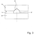
- FIG. 3 schematically shows the view from the outer periphery on an outer cooling ring 10 which rests on a blow head 20, in the region of a linear guide.
- This is again in the embodiment shown here by a radially extending recess 12 'in the outer cooling ring 10 and from the Blaskopfoberseite upstanding guide elements 22 'formed.
- the groove 12 'and the guide element 22' are V-shaped or wedge-shaped. The included angles are smaller in the convex parts, in this case the guide elements 22 ', than in the concave parts, here the grooves 12', so that only in the area of the tip a line contact takes place.
Landscapes
- Engineering & Computer Science (AREA)
- Mechanical Engineering (AREA)
- Extrusion Moulding Of Plastics Or The Like (AREA)
- Shaping By String And By Release Of Stress In Plastics And The Like (AREA)
Description
- Die Erfindung betrifft eine Schlauchfolienextrusionsvorrichtung mit einem Blaskopf und einem auf dessen Oberseite aufsetzbaren Außenkühlring, der an seiner Unterseite eine ringförmige Auflagefläche aufweist und über Zentriermittel gegenüber dem Blaskopf zentrierbar ist.
- Aus der
DE 33 36 181 A1 ist eine solche Vorrichtung bekannt. Der sogenannte Blaskopf besitzt einen ringförmigen Düsenspalt, aus dem Kunststoffschmelze austritt. In das Zentrum der Ringdüse wird Luft eingeblasen. Gleichzeitig wird von der Außenseite her mittels eines Außenkühlrings Luft gegen den an der Ringdüse austretenden Folienschlauch geleitet. Der Außenkühlring ist dabei mit einer Ringfläche an seiner Unterseite auf eine Ringfläche an der Oberseite des Blaskopfes aufgelegt, so dass der Außenkühlring leicht angehoben werden kann, um den Zugang zur Ringdüse bei der Wartung zu erleichtern. Problematisch ist hierbei, dass schon geringste Exzentrizitäten oder Schiefstellungen des aufliegenden Außenkühlrings dazu führen, dass die von der Ringdüse abgezogene Folienblase schief gestellt wird, was zu einer ungleichmäßigen Dickenverteilung bei der Folie sowie zu Problemen bei der weiteren Verarbeitung führen kann. - Die bei der bekannten Schlauchfolienextrusionsvorrichtung vorgesehenen Zentriermittel sind Schrauben, die an der Unterseite des Außenkühlrings in radialer Richtung ausgerichtet und in einer Gewindebohrung gelagert sind. Sie können mit ihrer Spitze gegen den Außenumfang eines kreisförmigen Abschnitts im oberen Bereich des Blaskopfes angestellt werden.
- Bei einer Schlauchfolienextrusionsvorrichtung gemäß der
DE 92 14 647 U1 erfolgt die Zentrierung durch einen kegelstumpfförmigen Absatz am Blaskopf, auf den der Außenkühlring mit einer kegeligen Bohrung aufgesetzt wird. - Weiterhin ist es bekannt, Zentriermittel durch hakenförmige Winkel zu bilden. Durch wenigstens drei Winkel an der Unterseite des Außenkühlrings kann die obere Kante des Blaskopfes umgriffen werden, wodurch der Zentrierring gegenüber dem Blaskopf zentriert wird.
- Allen bekannten Schlauchfolienextrusionsvorrichtungen ist gemeinsam, dass ihre Zentriermittel keine temperaturunabhängige Zentrierung erlauben. Eine bei Zimmertemperatur vorgenommene spielfreie Zentrierung von Kühlring und Blaskopf ist im Betrieb nicht wirksam, da die stärkere Erwärmung des Blaskopfes zu einer relativ größeren Ausdehnung als beim Kühlring führt. Auf Zentriermittel, die sich am Außenumfang von Teilen des Blaskopfes abstützen, würden somit erhebliche Druckkräfte wirken. Aus diesem Grund muss bei bekannten Schlauchfolienextrusionsvorrichtungen an jedem Betriebspunkt eine Zentrierung gesondert vorgenommen werden.
- Aufgabe der Erfindung ist es daher, eine temperaturunabhängige Zentrierung von Außenkühlring und Blaskopf zu ermöglichen.
- Gelöst wird diese Aufgabe bei einem Schlauchfolienwerkzeug der eingangs genannten Art dadurch, dass die Zentriermittel durch wenigstens drei radial angeordnete Linearführungen gebildet sind, welche jeweils eine sich radial erstreckende Ausnehmung und wenigstens ein darin eingreifendes Führungselement umfassen.
- Aufgrund der radialen Erstreckung der Linearführungen ist eine unterschiedliche Temperaturdehnung der beiden gegeneinander zu zentrierenden Teile in Umfangsrichtung möglich. Die Temperaturdehnung führt lediglich zu einer Relativverschiebung der Führungselemente innerhalb der Nut in radialer Richtung.
- Dadurch, dass wenigstens drei Linearführungen ausgebildet sind, ist eine Zwangszentrierung gegeben, ganz gleich, ob die Führungselemente an der Unterseite des Außenkühlrings oder an der Oberseite des Blaskopfes angeordnet sind, so dass beide Anordnungen möglich sind.
- Eine Ausbildung mit vier Nuten, von denen jeweils zwei auf einer gemeinsamen Durchmesserlinie liegen, also miteinander fluchten, vereinfacht die Fertigung und erhöht die Genauigkeit.
- Um das Aufsetzen des Kühlrings auf den Blaskopf zu erleichtern, wird eine Selbstzentrierung dadurch bewirkt, dass die Passfederelemente an ihren radial ausgerichteten Seitenkanten angeschrägt sind.
- Zusätzlich oder alternativ ist es möglich, die Nuten an deren radial ausgerichteten Seitenkanten anzuschrägen, so dass beim Aufsetzen die Passfederelemente leicht in die Nuten eingleiten.
- Anstelle der Passfederelemente können auch Stifte mit kreisrundem Querschnitt als Führungselemente vorgesehen sein. Der Vorteil der Stifte besteht darin, dass nur eine Linienberührung an beiden Flanken der Nut stattfindet und dass damit die Wärmeübertragung vom Blaskopf in das jeweilige Führungselement reduziert ist.
- Bei der erfindungsgemäßen Schlauchfolienextrusionsvorrichtung können Nut und Führungselement mit ihren Seitenabmessungen als Spielpassung ausgebildet sein, wobei die Passung so gewählt ist, dass auch bei maximaler Aufheizung des Blaskopfes im Betrieb sowie der gleichzeitigen maximalen Abkühlung des Blaskopfes in jedem Fall ein Gleiten der Führungselemente innerhalb der Nut möglich ist und ein Festklemmen verhindert wird.
- Um die Genauigkeit der Zentrierung in allen Betriebszuständen noch zu verbessern, werden folgende Maßnahmen vorgeschlagen:
- Eine Möglichkeit besteht darin, die Führungselemente aus einem Werkstoff herzustellen, der einen gleichartigen WärmeausdehnungsKoeffizienten besitzt wie die Gehäuse der Fügepartner im Bereich der Nuten. Zugleich werden die Führungselemente durch eine thermische Isolierung von dem Bauteil, an dem sie angebracht sind, entkoppelt. In diesem Fall ist eine Rechteckform des Führungselementes vorteilhaft, da so eine längere Linienberührung stattfindet und das Führungselement auf etwa dieselbe Temperatur aufgeheizt wird wie der Nutbereich, in das es eingreift. Folglich dehnen sich Nut und Führungselement im jeweiligen Eingriffspunkt in gleicher Weise aus, so dass eine entsprechend engere Passung gewählt werden kann und somit eine höhere Zentriergenauigkeit erzielt wird.
- Eine weitere mögliche Maßnahme, um das seitliche Spiel einschränken zu können, besteht darin, die Nut entweder ganz V-förmig auszugestalten oder zumindest den Nutgrund V-förmig einzufräsen und zugleich den Führungselementen an ihrer Spitze eine Keilform zu geben. Auch die umgekehrte Anordnung ist möglich, bei der vom Nutgrund eine V-förmige Rippe hoch steht, auf welche eine kompatible Vertiefung an der Spitze des Führungselements passt. Insbesondere, wenn die Keilformen nicht in ihren Winkeln übereinstimmen, wird eine scharf begrenzte Linienberührung erreicht, so dass die radiale Bewegung des Führungselements möglich ist, ohne dass es zu einem Einklemmen des Führungselements in der Nut kommt bzw zu einem Übermaß bei einer umgekehrten Anordnung, welches zu einer Ungenauigkeit führen könnte.
- Die Erfindung wird nachfolgend mit Bezug auf die Zeichnung näher erläutert. Die Figuren zeigen im Einzelnen:
- Figur 1
- die erfindungsgemäße Schlauchfolienextrusionsvorrichtung in perspektivischer Ansicht,
- Figur 2
- eine Draufsicht auf die Unterseite des Außenkühlrings und
- Figur 3
- Blaskopf und Außenkühlring in lagerichtiger, perspektivischer Darstellung.
-
Figur 1 zeigt mit einem Außenkühlring 10 und einem Blaskopf 20 notwendige Grundelemente einer Schlauchfolienextrusionsvorrichtung. Dabei ist der Blaskopf lagerichtig, also mit einer Oberseite nach oben weisend, dargestellt, wo hingegen der auf eine Ringfläche 21 an der Oberseite des Blaskopfes 20 auflegbare Kühlring 10 um 180° gedreht, also auf den Kopf gelegt ist, um den Blick auf die Unterseite und die dort angeordneten Zentrierelemente zu ermöglichen. - Auf der nach oben weisenden und horizontal ausgerichteten Ringfläche 21 des Blaskopfes 20 sind vier Führungselemente in Form von Passfedern 22.1, ..., 22.4 angeordnet, die exakt radial ausgerichtet sind, wie durch die strichpunktierten Durchmesserlinien angedeutet. Am Schnittpunkt der Durchmesserlinien liegen jeweils die zueinander zu zentrierenden Mittelpunkte 13, 23 des Außenkühlrings 10 und des Blaskopfes 20.
- An der Unterseite des Außenkühlrings 10 ist eine Kreisringfläche 11 vorhanden, in die vier Nuten 12.1, ..., 12.4 eingebracht sind, die sich genau radial erstrecken. Sowohl die Führungselemente 22.1, ..., 22.4, wie auch die Nuten 12.1, ..., 12.4 sind im dargestellten Ausführungsbeispiel jeweils um exakt 90° zueinander versetzt.
- Um Fertigungstoleranzen ausgleichen zu können, sind die Passfedem 22.1, ..., 22.4 zunächst über eine Schraube mit der Ringfläche 21 verbunden und werden dann, nach einer exakten Ausrichtung gegenüber den Nuten 12.1, ..., 12.4 durch Pass-Stifte endgültig in ihrer Lage gegenüber der Ringfläche 21 festgelegt.
-
Figur 2 zeigt die Anordnung der Nuten 12.1, ..., 12.4 noch einmal in einer Draufsicht auf die Unterseite mit ihrem ringförmigen, etwas erhabenen Auflagebereich 11. Gegenüberliegende Nuten 12.1, 12.3 bzw. 12.2, 12.4 liegen auf einer Durchmesserlinie, wobei die Durchmesserlinien um 90° versetzt zueinander ausgerichtet sind. -
Figur 3 zeigt schematisch den Blick vom Außenumfang her auf einen Außenkühlring 10, der auf einem Blaskopf 20 aufliegt, im Bereich einer Linearführung. Diese ist bei dem hier dargestellten Ausführungsbeispiel wiederum durch eine sich radial erstreckende Vertiefung 12' im Außenkühlring 10 und von der Blaskopfoberseite aufragende Führungselemente 22' gebildet. Die Nut 12' und das Führungselement 22' sind V-förmig bzw. keilförmig ausgebildet. Die eingeschlossenen Winkel sind bei den konvexen Teilen, hier den Führungselementen 22', kleiner als bei den konkaven Teilen, hier den Nuten 12', so dass nur im Bereich der Spitze eine Linienberührung stattfindet.Bezugszeichenliste 10 Außenkühlring 11 Kreisringfläche 12' Nut 12.1 Nut 12.2 Nut 12.3 Nut 12.4 Nut 13 Zentrierender Mittelpunkt 20 Blaskopf 21 Ringfläche 22' Führungselement 22.1 Führungselement 22.2 Führungselement 22.3 Führungselement 22.4 Führungselement 23 Zentrierender Mittelpunkt
Claims (11)
- Schlauchfolienextrusionsvorrichtung mit einem Blaskopf (20) und einem auf dessen Oberseite (21) aufsetzbaren Außenkühlring (10), der an seiner Unterseite eine ringförmige Auflagefläche (11) aufweist und über Zentriermittel gegenüber dem Blaskopf (10) zentrierbar ist,
dadurch gekennzeichnet, dass
die Zentriermittel durch wenigstens drei radial angeordnete Linearführungen gebildet sind, welche jeweils eine sich radial erstreckende Ausnehmung (12.1,..., 12. 4) und wenigstens ein darin eingreifendes Führungselement (22.1,..., 22.4) umfassen. - Schlauchfolienextrusionsvorrichtung nach Anspruch 1,
dadurch gekennzeichnet, dass
die Linearführungen durch Nuten (12.1,..., 12.4) an der Unterseite (11) des Außenkühlrings (10) und darin eingreifende Führungselemente (22.1,...,22.4), die von der Oberseite (21) des Blaskopfes (20) abstehen, gebildet sind. - Schlauchfolienextrusionsvorrichtung nach Anspruch 1,
dadurch gekennzeichnet, dass
die Linearführungen durch Nuten an der Oberseite des Blaskopfes und darin eingreifende Führungselemente, die von der Unterseite des Außenkühlrings abstehen, gebildet sind. - Schlauchfolienextrusionsvorrichtung nach Anspruch 2 oder 3,
dadurch gekennzeichnet, dass
die Führungselemente (22.1,...,22.4) durch radial ausgerichtete Passfederelemente gebildet sind. - Schlauchfolienextrusionsvorrichtung nach Anspruch 4,
dadurch gekennzeichnet, dass
die Passfederelemente (22.1,...,22.4) an ihren radial ausgerichteten Seitenkanten angeschrägt sind. - Schlauchfolienextrusionsvorrichtung nach Anspruch 2 oder 3,
dadurch gekennzeichnet, dass
die Führungselemente durch Stifte mit kreisrundem Querschnitt gebildet sind. - Schlauchfolienextrusionsvorrichtung nach einem der Ansprüche 2 bis 6,
dadurch gekennzeichnet, dass
die Nuten (12.1,...,12.4) an ihren radial ausgerichteten Seitenkanten angeschrägt sind. - Schlauchfolienextrusionsvorrichtung nach einem der Ansprüche 1 bis 7,
dadurch gekennzeichnet, dass
vier Nuten (12.1,...,12.4) vorgesehen sind, von denen jeweils zwei auf einer gemeinsamen Durchmesserlinie liegen. - Schlauchfolienextrusionsvorrichtung nach einem der Ansprüche 1 bis 8,
dadurch gekennzeichnet, dass
die Führungselemente (22.1,..., 22.4) thermisch entkoppelt angebracht ausgebildet sind. - Schlauchfolienextrusionsvorrichtung nach einem der Ansprüche 1 bis 9,
dadurch gekennzeichnet, dass
in einem Schnitt quer zur radialen Erstreckung der Nuten (12') zumindest der Nutgrund V-förmig eingetieft ist und die Führungselemente (22') wenigstens an ihrer zum Nutgrund (12') weisenden Außenseite keilförmig ausgebildet sind. - Schlauchfolienextrusionsvorrichtung nach einem der Ansprüche 1 bis 9,
dadurch gekennzeichnet, dass
in einem Schnitt quer zur radialen Erstreckung der Nuten auf dem Nutgrund zumindest eine V-förmige Rippe ausgebildet ist und die Führungselemente wenigstens an ihrer zum Nutgrund weisenden Außenseite mit einer keilförmigen Nut profiliert sind.
Applications Claiming Priority (2)
| Application Number | Priority Date | Filing Date | Title |
|---|---|---|---|
| DE102006039563A DE102006039563B3 (de) | 2006-08-23 | 2006-08-23 | Schlauchfolienextrusionsvorrichtung |
| PCT/EP2007/007285 WO2008022749A1 (de) | 2006-08-23 | 2007-08-15 | Schlauchfolienextrusionsvorrichtung |
Publications (2)
| Publication Number | Publication Date |
|---|---|
| EP2054213A1 EP2054213A1 (de) | 2009-05-06 |
| EP2054213B1 true EP2054213B1 (de) | 2010-02-17 |
Family
ID=38565119
Family Applications (1)
| Application Number | Title | Priority Date | Filing Date |
|---|---|---|---|
| EP07801729A Active EP2054213B1 (de) | 2006-08-23 | 2007-08-15 | Schlauchfolienextrusionsvorrichtung |
Country Status (7)
| Country | Link |
|---|---|
| US (1) | US8360763B2 (de) |
| EP (1) | EP2054213B1 (de) |
| CN (1) | CN101563205B (de) |
| AT (1) | ATE457865T1 (de) |
| CA (1) | CA2661392C (de) |
| DE (2) | DE102006039563B3 (de) |
| WO (1) | WO2008022749A1 (de) |
Families Citing this family (3)
| Publication number | Priority date | Publication date | Assignee | Title |
|---|---|---|---|---|
| DE102019124586B3 (de) * | 2019-09-12 | 2021-01-21 | Reifenhäuser GmbH & Co. KG Maschinenfabrik | Blaskopf für eine Extrusionsanlage, Extrusionsanlage und Verfahren zur Vergleichmäßigung einer Wanddickenverteilung |
| US11618200B2 (en) | 2020-03-17 | 2023-04-04 | Michael P. Bucko | External cooling air ring for blown-film extrusion |
| US11826941B1 (en) * | 2022-06-28 | 2023-11-28 | Daniel R. Joseph | Air ring for blown-film extrusion apparatus |
Family Cites Families (12)
| Publication number | Priority date | Publication date | Assignee | Title |
|---|---|---|---|---|
| DE78368C (de) | F. BRANDSTAEDTER, Louvain, Belgien | Transportvorrichtung für körnige und pulverförmige Massen | ||
| DD78368A1 (de) * | 1969-05-22 | 1970-12-12 | Manfred Gräser | Kühlvorrichtuntg zur herstellung von schlauchfolien |
| US4145177A (en) * | 1977-12-12 | 1979-03-20 | Gloucester Engineering Co., Inc. | Air cooling ring for plastic film with independent lubricating air for film guide surface |
| DE3461696D1 (en) * | 1983-03-31 | 1987-01-29 | Windmoeller & Hoelscher | Cooling device for blow-head extruded tubular plastic films |
| DE3336181A1 (de) * | 1983-10-05 | 1985-04-25 | Overbeck GmbH & Co, 2800 Bremen | Vorrichtung zum kuehlen eines aus insbesondere einem extruderspritzkopf austretenden thermoplastischen folienschlauches |
| DE3436881A1 (de) * | 1984-10-08 | 1986-04-10 | Windmöller & Hölscher, 4540 Lengerich | Kuehlvorrichtung fuer aus einem folienblaskopf extrudierte kunststoffschlauchfolien |
| JPS6424725A (en) * | 1987-07-22 | 1989-01-26 | Tomy Kikai Kogyo Kk | Cooling apparatus for forming inflation film |
| DE9214647U1 (de) * | 1992-10-28 | 1993-03-11 | Windmöller & Hölscher, 4540 Lengerich | Vorrichtung zur Zentrierung einer Folienschlauchblase am Kopf eines Blasfolienextruders |
| CN1218739A (zh) * | 1997-11-28 | 1999-06-09 | 马科工程及技术公司 | 用于冷却吹塑薄膜的气流环 |
| DE20022174U1 (de) * | 1999-09-09 | 2001-05-17 | Kdesign GmbH, 51371 Leverkusen | Vorrichtung zur Steuerung und Regelung des Dickenprofils bei der Blasfolienherstellung |
| NL1016669C2 (nl) * | 2000-11-21 | 2002-05-22 | Axxicon Moulds Eindhoven Bv | Matrijssamenstel voorzien van centrering. |
| CN1287973C (zh) * | 2002-08-30 | 2006-12-06 | 可乐丽股份有限公司 | 吹塑薄膜的生产设备和生产方法 |
-
2006
- 2006-08-23 DE DE102006039563A patent/DE102006039563B3/de not_active Expired - Fee Related
-
2007
- 2007-08-15 WO PCT/EP2007/007285 patent/WO2008022749A1/de not_active Ceased
- 2007-08-15 CA CA2661392A patent/CA2661392C/en not_active Expired - Fee Related
- 2007-08-15 AT AT07801729T patent/ATE457865T1/de active
- 2007-08-15 US US12/310,361 patent/US8360763B2/en not_active Expired - Fee Related
- 2007-08-15 CN CN2007800395413A patent/CN101563205B/zh not_active Expired - Fee Related
- 2007-08-15 DE DE502007002877T patent/DE502007002877D1/de active Active
- 2007-08-15 EP EP07801729A patent/EP2054213B1/de active Active
Also Published As
| Publication number | Publication date |
|---|---|
| CA2661392A1 (en) | 2008-02-28 |
| DE102006039563B3 (de) | 2007-11-08 |
| ATE457865T1 (de) | 2010-03-15 |
| CN101563205A (zh) | 2009-10-21 |
| CN101563205B (zh) | 2013-02-06 |
| US8360763B2 (en) | 2013-01-29 |
| DE502007002877D1 (de) | 2010-04-01 |
| US20090252819A1 (en) | 2009-10-08 |
| EP2054213A1 (de) | 2009-05-06 |
| WO2008022749A1 (de) | 2008-02-28 |
| CA2661392C (en) | 2014-12-09 |
Similar Documents
| Publication | Publication Date | Title |
|---|---|---|
| EP1160609B1 (de) | Vorrichtung zur präzisen Positionierung eines Bauteiles, insbesondere eines optischen Bauteiles | |
| EP1240963B1 (de) | Verbindungsstelle | |
| EP2167267B1 (de) | Dehnreibahle | |
| EP3582917B1 (de) | Lochsäge | |
| EP3566850B1 (de) | Mehrfachextrusionskopf | |
| EP0751851A1 (de) | Rundlaufwerkzeug mit wuchtringen | |
| EP2586595A1 (de) | Verfahren zum Verbinden eines Kunststoffwerkstücks mit einem weiteren Werkstück | |
| WO2016139151A1 (de) | Pulverpresse sowie ein futtergehäuse mit vorzugsweise mehreren für ein querpressen verschiebbaren stempeln | |
| WO2008022749A1 (de) | Schlauchfolienextrusionsvorrichtung | |
| EP0962280B1 (de) | Ausrichteinrichtung | |
| EP3418025B1 (de) | Umlenkvorrichtung zur umlenkung eines schmelzeflusses innerhalb einer verteilerplatte | |
| EP4140677B1 (de) | Schlüsselaufsatz | |
| DE2848202C2 (de) | Verschluß für ein Gefäß großen Durchmessers | |
| DE3713023C2 (de) | Vorrichtung zum Spannen von Paletten | |
| EP4021147B1 (de) | Induktionsheizvorrichtung, hüllenelement und verfahren zu einem verschleissschutz eines magnetflussleitelements durch das hüllenelement | |
| EP2260974A1 (de) | Werkstückhalter für eine Planschleifmaschine | |
| EP2695718B1 (de) | Zentrierelement für Werkzeugteilelemente eines Kunststoffverarbeitungswerkzeugs | |
| EP1704945A1 (de) | Auswerfersystem für Formkästen | |
| DE102010012359A1 (de) | Vorrichtung zum Verschweißen von Profilteilen | |
| DE19647607C2 (de) | Vorrichtung zur Festlegung von zweischaligen Isolierglasscheiben an Tragkonstruktionen | |
| DE3928971A1 (de) | Ausgleichselement zum ausgleichen von positions- und/oder winkelabweichungen beim maschinellen zusammenfuegen von bauteilen | |
| EP1224049A1 (de) | Gedämpftes werkzeug | |
| DE20320068U1 (de) | Verbindung zweier Maschinenteile | |
| DE102019120208B3 (de) | Scharnier, insbesondere verstellbares Türscharnier sowie Tür | |
| DE102013226412B4 (de) | Spannmodul, insbesondere Nullpunktspannmodul und zugehöriges Spannsystem |
Legal Events
| Date | Code | Title | Description |
|---|---|---|---|
| PUAI | Public reference made under article 153(3) epc to a published international application that has entered the european phase |
Free format text: ORIGINAL CODE: 0009012 |
|
| 17P | Request for examination filed |
Effective date: 20090121 |
|
| AK | Designated contracting states |
Kind code of ref document: A1 Designated state(s): AT BE BG CH CY CZ DE DK EE ES FI FR GB GR HU IE IS IT LI LT LU LV MC MT NL PL PT RO SE SI SK TR |
|
| AX | Request for extension of the european patent |
Extension state: AL BA HR MK RS |
|
| GRAP | Despatch of communication of intention to grant a patent |
Free format text: ORIGINAL CODE: EPIDOSNIGR1 |
|
| GRAS | Grant fee paid |
Free format text: ORIGINAL CODE: EPIDOSNIGR3 |
|
| GRAA | (expected) grant |
Free format text: ORIGINAL CODE: 0009210 |
|
| AK | Designated contracting states |
Kind code of ref document: B1 Designated state(s): AT BE BG CH CY CZ DE DK EE ES FI FR GB GR HU IE IS IT LI LT LU LV MC MT NL PL PT RO SE SI SK TR |
|
| REG | Reference to a national code |
Ref country code: GB Ref legal event code: FG4D Free format text: NOT ENGLISH |
|
| REG | Reference to a national code |
Ref country code: CH Ref legal event code: NV Representative=s name: BOVARD AG PATENTANWAELTE Ref country code: CH Ref legal event code: EP |
|
| REG | Reference to a national code |
Ref country code: IE Ref legal event code: FG4D Free format text: LANGUAGE OF EP DOCUMENT: GERMAN |
|
| REF | Corresponds to: |
Ref document number: 502007002877 Country of ref document: DE Date of ref document: 20100401 Kind code of ref document: P |
|
| REG | Reference to a national code |
Ref country code: NL Ref legal event code: VDEP Effective date: 20100217 |
|
| LTIE | Lt: invalidation of european patent or patent extension |
Effective date: 20100217 |
|
| PG25 | Lapsed in a contracting state [announced via postgrant information from national office to epo] |
Ref country code: IS Free format text: LAPSE BECAUSE OF FAILURE TO SUBMIT A TRANSLATION OF THE DESCRIPTION OR TO PAY THE FEE WITHIN THE PRESCRIBED TIME-LIMIT Effective date: 20100617 Ref country code: PT Free format text: LAPSE BECAUSE OF FAILURE TO SUBMIT A TRANSLATION OF THE DESCRIPTION OR TO PAY THE FEE WITHIN THE PRESCRIBED TIME-LIMIT Effective date: 20100617 Ref country code: ES Free format text: LAPSE BECAUSE OF FAILURE TO SUBMIT A TRANSLATION OF THE DESCRIPTION OR TO PAY THE FEE WITHIN THE PRESCRIBED TIME-LIMIT Effective date: 20100528 Ref country code: LT Free format text: LAPSE BECAUSE OF FAILURE TO SUBMIT A TRANSLATION OF THE DESCRIPTION OR TO PAY THE FEE WITHIN THE PRESCRIBED TIME-LIMIT Effective date: 20100217 |
|
| PG25 | Lapsed in a contracting state [announced via postgrant information from national office to epo] |
Ref country code: LV Free format text: LAPSE BECAUSE OF FAILURE TO SUBMIT A TRANSLATION OF THE DESCRIPTION OR TO PAY THE FEE WITHIN THE PRESCRIBED TIME-LIMIT Effective date: 20100217 Ref country code: PL Free format text: LAPSE BECAUSE OF FAILURE TO SUBMIT A TRANSLATION OF THE DESCRIPTION OR TO PAY THE FEE WITHIN THE PRESCRIBED TIME-LIMIT Effective date: 20100217 Ref country code: SI Free format text: LAPSE BECAUSE OF FAILURE TO SUBMIT A TRANSLATION OF THE DESCRIPTION OR TO PAY THE FEE WITHIN THE PRESCRIBED TIME-LIMIT Effective date: 20100217 Ref country code: FI Free format text: LAPSE BECAUSE OF FAILURE TO SUBMIT A TRANSLATION OF THE DESCRIPTION OR TO PAY THE FEE WITHIN THE PRESCRIBED TIME-LIMIT Effective date: 20100217 |
|
| REG | Reference to a national code |
Ref country code: IE Ref legal event code: FD4D |
|
| PG25 | Lapsed in a contracting state [announced via postgrant information from national office to epo] |
Ref country code: RO Free format text: LAPSE BECAUSE OF FAILURE TO SUBMIT A TRANSLATION OF THE DESCRIPTION OR TO PAY THE FEE WITHIN THE PRESCRIBED TIME-LIMIT Effective date: 20100217 Ref country code: SE Free format text: LAPSE BECAUSE OF FAILURE TO SUBMIT A TRANSLATION OF THE DESCRIPTION OR TO PAY THE FEE WITHIN THE PRESCRIBED TIME-LIMIT Effective date: 20100217 Ref country code: CY Free format text: LAPSE BECAUSE OF FAILURE TO SUBMIT A TRANSLATION OF THE DESCRIPTION OR TO PAY THE FEE WITHIN THE PRESCRIBED TIME-LIMIT Effective date: 20100217 Ref country code: EE Free format text: LAPSE BECAUSE OF FAILURE TO SUBMIT A TRANSLATION OF THE DESCRIPTION OR TO PAY THE FEE WITHIN THE PRESCRIBED TIME-LIMIT Effective date: 20100217 Ref country code: GR Free format text: LAPSE BECAUSE OF FAILURE TO SUBMIT A TRANSLATION OF THE DESCRIPTION OR TO PAY THE FEE WITHIN THE PRESCRIBED TIME-LIMIT Effective date: 20100518 Ref country code: IE Free format text: LAPSE BECAUSE OF FAILURE TO SUBMIT A TRANSLATION OF THE DESCRIPTION OR TO PAY THE FEE WITHIN THE PRESCRIBED TIME-LIMIT Effective date: 20100217 Ref country code: NL Free format text: LAPSE BECAUSE OF FAILURE TO SUBMIT A TRANSLATION OF THE DESCRIPTION OR TO PAY THE FEE WITHIN THE PRESCRIBED TIME-LIMIT Effective date: 20100217 |
|
| PG25 | Lapsed in a contracting state [announced via postgrant information from national office to epo] |
Ref country code: BG Free format text: LAPSE BECAUSE OF FAILURE TO SUBMIT A TRANSLATION OF THE DESCRIPTION OR TO PAY THE FEE WITHIN THE PRESCRIBED TIME-LIMIT Effective date: 20100517 Ref country code: SK Free format text: LAPSE BECAUSE OF FAILURE TO SUBMIT A TRANSLATION OF THE DESCRIPTION OR TO PAY THE FEE WITHIN THE PRESCRIBED TIME-LIMIT Effective date: 20100217 Ref country code: CZ Free format text: LAPSE BECAUSE OF FAILURE TO SUBMIT A TRANSLATION OF THE DESCRIPTION OR TO PAY THE FEE WITHIN THE PRESCRIBED TIME-LIMIT Effective date: 20100217 |
|
| PLBE | No opposition filed within time limit |
Free format text: ORIGINAL CODE: 0009261 |
|
| STAA | Information on the status of an ep patent application or granted ep patent |
Free format text: STATUS: NO OPPOSITION FILED WITHIN TIME LIMIT |
|
| 26N | No opposition filed |
Effective date: 20101118 |
|
| PG25 | Lapsed in a contracting state [announced via postgrant information from national office to epo] |
Ref country code: DK Free format text: LAPSE BECAUSE OF FAILURE TO SUBMIT A TRANSLATION OF THE DESCRIPTION OR TO PAY THE FEE WITHIN THE PRESCRIBED TIME-LIMIT Effective date: 20100217 |
|
| BERE | Be: lapsed |
Owner name: WINDMOLLER & HOLSCHER K.G. Effective date: 20100831 |
|
| PG25 | Lapsed in a contracting state [announced via postgrant information from national office to epo] |
Ref country code: MC Free format text: LAPSE BECAUSE OF NON-PAYMENT OF DUE FEES Effective date: 20100831 |
|
| REG | Reference to a national code |
Ref country code: CH Ref legal event code: PFA Owner name: WINDMOELLER & HOELSCHER KG Free format text: WINDMOELLER & HOELSCHER KG#MUENSTERSTRASSE 50#49525 LENGERICH (DE) -TRANSFER TO- WINDMOELLER & HOELSCHER KG#MUENSTERSTRASSE 50#49525 LENGERICH (DE) |
|
| REG | Reference to a national code |
Ref country code: FR Ref legal event code: ST Effective date: 20110502 |
|
| PG25 | Lapsed in a contracting state [announced via postgrant information from national office to epo] |
Ref country code: FR Free format text: LAPSE BECAUSE OF NON-PAYMENT OF DUE FEES Effective date: 20100831 Ref country code: BE Free format text: LAPSE BECAUSE OF NON-PAYMENT OF DUE FEES Effective date: 20100831 |
|
| PG25 | Lapsed in a contracting state [announced via postgrant information from national office to epo] |
Ref country code: MT Free format text: LAPSE BECAUSE OF FAILURE TO SUBMIT A TRANSLATION OF THE DESCRIPTION OR TO PAY THE FEE WITHIN THE PRESCRIBED TIME-LIMIT Effective date: 20100217 |
|
| GBPC | Gb: european patent ceased through non-payment of renewal fee |
Effective date: 20110815 |
|
| PG25 | Lapsed in a contracting state [announced via postgrant information from national office to epo] |
Ref country code: GB Free format text: LAPSE BECAUSE OF NON-PAYMENT OF DUE FEES Effective date: 20110815 |
|
| PG25 | Lapsed in a contracting state [announced via postgrant information from national office to epo] |
Ref country code: LU Free format text: LAPSE BECAUSE OF NON-PAYMENT OF DUE FEES Effective date: 20100815 Ref country code: HU Free format text: LAPSE BECAUSE OF FAILURE TO SUBMIT A TRANSLATION OF THE DESCRIPTION OR TO PAY THE FEE WITHIN THE PRESCRIBED TIME-LIMIT Effective date: 20100818 |
|
| PG25 | Lapsed in a contracting state [announced via postgrant information from national office to epo] |
Ref country code: TR Free format text: LAPSE BECAUSE OF FAILURE TO SUBMIT A TRANSLATION OF THE DESCRIPTION OR TO PAY THE FEE WITHIN THE PRESCRIBED TIME-LIMIT Effective date: 20100217 |
|
| REG | Reference to a national code |
Ref country code: DE Ref legal event code: R079 Ref document number: 502007002877 Country of ref document: DE Free format text: PREVIOUS MAIN CLASS: B29C0047880000 Ipc: B29C0048880000 |
|
| PGFP | Annual fee paid to national office [announced via postgrant information from national office to epo] |
Ref country code: CH Payment date: 20180824 Year of fee payment: 12 Ref country code: AT Payment date: 20180828 Year of fee payment: 12 |
|
| REG | Reference to a national code |
Ref country code: AT Ref legal event code: MM01 Ref document number: 457865 Country of ref document: AT Kind code of ref document: T Effective date: 20190815 |
|
| PG25 | Lapsed in a contracting state [announced via postgrant information from national office to epo] |
Ref country code: AT Free format text: LAPSE BECAUSE OF NON-PAYMENT OF DUE FEES Effective date: 20190815 |
|
| PG25 | Lapsed in a contracting state [announced via postgrant information from national office to epo] |
Ref country code: LI Free format text: LAPSE BECAUSE OF NON-PAYMENT OF DUE FEES Effective date: 20190831 Ref country code: CH Free format text: LAPSE BECAUSE OF NON-PAYMENT OF DUE FEES Effective date: 20190831 |
|
| PGFP | Annual fee paid to national office [announced via postgrant information from national office to epo] |
Ref country code: DE Payment date: 20250831 Year of fee payment: 19 |
|
| PGFP | Annual fee paid to national office [announced via postgrant information from national office to epo] |
Ref country code: IT Payment date: 20250825 Year of fee payment: 19 |