EP2053743A2 - Wireless surface acoustic wave-based proximity sensor, sensing system and method - Google Patents
Wireless surface acoustic wave-based proximity sensor, sensing system and method Download PDFInfo
- Publication number
- EP2053743A2 EP2053743A2 EP08018238A EP08018238A EP2053743A2 EP 2053743 A2 EP2053743 A2 EP 2053743A2 EP 08018238 A EP08018238 A EP 08018238A EP 08018238 A EP08018238 A EP 08018238A EP 2053743 A2 EP2053743 A2 EP 2053743A2
- Authority
- EP
- European Patent Office
- Prior art keywords
- sensing element
- proximity sensor
- magnet
- wireless proximity
- recited
- Prior art date
- Legal status (The legal status is an assumption and is not a legal conclusion. Google has not performed a legal analysis and makes no representation as to the accuracy of the status listed.)
- Granted
Links
- 238000010897 surface acoustic wave method Methods 0.000 title claims abstract description 63
- 238000000034 method Methods 0.000 title claims description 11
- 239000000463 material Substances 0.000 claims abstract description 48
- 230000005291 magnetic effect Effects 0.000 claims abstract description 25
- 230000004044 response Effects 0.000 claims abstract description 18
- 239000000758 substrate Substances 0.000 claims description 20
- PXHVJJICTQNCMI-UHFFFAOYSA-N Nickel Chemical compound [Ni] PXHVJJICTQNCMI-UHFFFAOYSA-N 0.000 claims description 12
- 230000008859 change Effects 0.000 claims description 9
- 229910017052 cobalt Inorganic materials 0.000 claims description 6
- 239000010941 cobalt Substances 0.000 claims description 6
- GUTLYIVDDKVIGB-UHFFFAOYSA-N cobalt atom Chemical compound [Co] GUTLYIVDDKVIGB-UHFFFAOYSA-N 0.000 claims description 6
- 229910052759 nickel Inorganic materials 0.000 claims description 6
- 239000010409 thin film Substances 0.000 claims description 4
- 229910001218 Gallium arsenide Inorganic materials 0.000 claims description 3
- 229910003327 LiNbO3 Inorganic materials 0.000 claims description 3
- 229910012463 LiTaO3 Inorganic materials 0.000 claims description 3
- 229910000147 aluminium phosphate Inorganic materials 0.000 claims description 3
- 239000010453 quartz Substances 0.000 claims description 3
- VYPSYNLAJGMNEJ-UHFFFAOYSA-N silicon dioxide Inorganic materials O=[Si]=O VYPSYNLAJGMNEJ-UHFFFAOYSA-N 0.000 claims description 3
- XEEYBQQBJWHFJM-UHFFFAOYSA-N Iron Chemical compound [Fe] XEEYBQQBJWHFJM-UHFFFAOYSA-N 0.000 description 4
- 239000013590 bulk material Substances 0.000 description 4
- 230000008901 benefit Effects 0.000 description 3
- 238000001514 detection method Methods 0.000 description 3
- 239000003302 ferromagnetic material Substances 0.000 description 3
- 239000010408 film Substances 0.000 description 3
- 238000002955 isolation Methods 0.000 description 3
- 230000010363 phase shift Effects 0.000 description 3
- 229910017083 AlN Inorganic materials 0.000 description 2
- 239000013078 crystal Substances 0.000 description 2
- 238000013461 design Methods 0.000 description 2
- 238000005516 engineering process Methods 0.000 description 2
- 229910052742 iron Inorganic materials 0.000 description 2
- 239000002184 metal Substances 0.000 description 2
- 229910052751 metal Inorganic materials 0.000 description 2
- 230000007935 neutral effect Effects 0.000 description 2
- 230000003287 optical effect Effects 0.000 description 2
- 230000035699 permeability Effects 0.000 description 2
- CWYNVVGOOAEACU-UHFFFAOYSA-N Fe2+ Chemical compound [Fe+2] CWYNVVGOOAEACU-UHFFFAOYSA-N 0.000 description 1
- 206010070245 Foreign body Diseases 0.000 description 1
- 239000000853 adhesive Substances 0.000 description 1
- 230000001070 adhesive effect Effects 0.000 description 1
- 230000005540 biological transmission Effects 0.000 description 1
- 230000006835 compression Effects 0.000 description 1
- 238000007906 compression Methods 0.000 description 1
- 238000009833 condensation Methods 0.000 description 1
- 230000005494 condensation Effects 0.000 description 1
- 238000011109 contamination Methods 0.000 description 1
- 230000005672 electromagnetic field Effects 0.000 description 1
- 239000012530 fluid Substances 0.000 description 1
- 230000006698 induction Effects 0.000 description 1
- 238000009434 installation Methods 0.000 description 1
- 230000003993 interaction Effects 0.000 description 1
- 239000002648 laminated material Substances 0.000 description 1
- 239000000696 magnetic material Substances 0.000 description 1
- 238000004519 manufacturing process Methods 0.000 description 1
- 230000000873 masking effect Effects 0.000 description 1
- 238000012986 modification Methods 0.000 description 1
- 230000004048 modification Effects 0.000 description 1
- 230000008569 process Effects 0.000 description 1
- 238000012545 processing Methods 0.000 description 1
- 238000012546 transfer Methods 0.000 description 1
- XLYOFNOQVPJJNP-UHFFFAOYSA-N water Substances O XLYOFNOQVPJJNP-UHFFFAOYSA-N 0.000 description 1
Images


Classifications
-
- H—ELECTRICITY
- H03—ELECTRONIC CIRCUITRY
- H03K—PULSE TECHNIQUE
- H03K17/00—Electronic switching or gating, i.e. not by contact-making and –breaking
- H03K17/94—Electronic switching or gating, i.e. not by contact-making and –breaking characterised by the way in which the control signals are generated
-
- H—ELECTRICITY
- H03—ELECTRONIC CIRCUITRY
- H03K—PULSE TECHNIQUE
- H03K17/00—Electronic switching or gating, i.e. not by contact-making and –breaking
- H03K17/94—Electronic switching or gating, i.e. not by contact-making and –breaking characterised by the way in which the control signals are generated
- H03K17/945—Proximity switches
- H03K17/95—Proximity switches using a magnetic detector
-
- H—ELECTRICITY
- H03—ELECTRONIC CIRCUITRY
- H03K—PULSE TECHNIQUE
- H03K17/00—Electronic switching or gating, i.e. not by contact-making and –breaking
- H03K17/94—Electronic switching or gating, i.e. not by contact-making and –breaking characterised by the way in which the control signals are generated
- H03K17/965—Switches controlled by moving an element forming part of the switch
- H03K17/97—Switches controlled by moving an element forming part of the switch using a magnetic movable element
-
- H—ELECTRICITY
- H03—ELECTRONIC CIRCUITRY
- H03K—PULSE TECHNIQUE
- H03K2217/00—Indexing scheme related to electronic switching or gating, i.e. not by contact-making or -breaking covered by H03K17/00
- H03K2217/94—Indexing scheme related to electronic switching or gating, i.e. not by contact-making or -breaking covered by H03K17/00 characterised by the way in which the control signal is generated
- H03K2217/96—Touch switches
- H03K2217/96003—Touch switches using acoustic waves, e.g. ultrasound
- H03K2217/96011—Touch switches using acoustic waves, e.g. ultrasound with propagation, SAW or BAW
Definitions
- the subject invention is related to proximity sensors for detection of a position of an object, and more particularly, to a wireless proximity sensor and sensing system that uses surface acoustic wave (SAW) technology to reduce weight and complexity to meet the rigorous demands of the aviation industry and other position sensing applications.
- SAW surface acoustic wave
- Proximity sensors have long been used to indicate the position of an object on an aircraft or other vehicle (e.g., whether a door or hatch is open or closed). These proximity sensors are typically the current sensing induction type and heavily armored for isolation. The proximity sensor generates an electromagnetic field to sense metal objects passing within a few tenths of inches.
- the heavy isolation armor or shielding and wire required are highly undesirable in the field of weight sensitive aircraft design.
- each extra pound has a recurring cost of over U.S. $500, a non-recurring cost of over U.S. $5000, and a life cycle cost of U.S. $100,000.
- rotary wing craft e.g., helicopters
- the costs are typically twice that of fixed wing aircraft.
- a Boeing 787 airplane has approximately 150 proximity sensors with over 40 pounds of associated wire.
- SAW devices having a magnetostrictive element are one type of electronic component that may be used to address the problems of weight sensitive proximity detection of objects in aircraft and other applications.
- SAW devices generate guided acoustic waves along a surface of the device.
- SAW devices are typically fabricated on single crystal anisotropic substrates that are also piezoelectric.
- SAW devices typically include one or more pairs of intertwined interdigital electrodes that form transducers (known as an interdigital transducer or IDT) to convert the electrical signals applied to the device into the electromechanical surface acoustic waves generated in the device and vice versa.
- IDT interdigital transducer
- SAW devices may also be present in different classes of acoustic devices such as micro-strip couplers and acoustic reflectors/mirrors etc., depending on the particular device configuration employed.
- U.S. Patent No. 4,078,186 discloses a magnetically tuned SAW device having a thin magnetostrictive film deposited only on the surface between its input and output transducers.
- a variable DC magnetic field is applied to the film by connecting the poles of an electromagnet to a DC supply.
- the electromagnet is then placed in line with the plane of the film to vary its magnetic field characteristics.
- a corresponding continuous variance in the delay or phase shift of the surface acoustic wave is produced thereby.
- This configuration however, has several drawbacks that do not make it ideal for proximity sensing applications. These drawbacks include, but are not limited to, the stationary positioning of the electromagnet and the weight of the wiring necessary to supply DC current to the poles of the electromagnet.
- the present invention discloses a number of improvements over this and other known SAW devices and methods for proximity sensing, the features and advantages of which are described herein.
- the subject invention is directed to a wireless proximity sensor, wireless proximity sensing system, and method that uses SAW technology in conjunction with magnetostrictive materials to detect the position of objects.
- a sensor and sensing system is advantageous because it eliminates the need for heavy, complex and difficult to maintain sensors and sensor wiring.
- the device fabrication is simpler and requires fewer mask and processing steps with the added benefit of small proximity sensor device dimensions.
- a first embodiment of the wireless proximity sensor according to the present invention is a wireless proximity sensor for sensing the position of an object comprising a body formed of a substrate material having an upper surface, a lower surface, a first end and a second end.
- the sensor of this embodiment is further comprised of one or more IDTs provided on the upper surface of the first end of the body, wherein each of the IDTs has at least one associated antenna.
- IDTs provided on the upper surface of the first end of the body, wherein each of the IDTs has at least one associated antenna.
- other classes of SAW devices may be used such as micro-strip couplers and acoustic reflectors/mirrors.
- a sensing element formed of magnetostrictive material is also attached to or deposited on the substrate material.
- One or more magnets are further provided as well as one or more movable targets.
- the target made of ferromagnetic material, is positioned to provide a reference point of the position of an object.
- the movement of the target acts upon the magnetic field of the magnet, which can be attached to any one of the surfaces of the sensing element or the SAW device body by an elastic attaching means disposed between the magnet and the sensing element.
- the means for attaching may include a biasing means such as an elastic rod or spring or other means known in the art.
- the magnet is therefore capable of movement with respect to the sensing element and the SAW device body.
- the resultant change in distance and position of the movement of the magnet relative to the sensing element induces a mechanical response in the sensing element(s) and the SAW device attached thereto, which provides information about the position of the object of which the desired position is to be detected.
- the means for attaching of the first embodiment may include a biasing means such as an elastic rod, spring or the like.
- the substrate material of the body may be one of Quartz, LiNbO 3 , AlN, AlPO 4 , LiTaO 3 , Lagasite, Bi 4 Ge 3 O 12 (BGO), GaAs, PZT or any equivalent known in the art.
- the magnetostrictive material of the sensing element may be selected from the group consisting of TERFENOL-D, Galfenol, Cobalt, and Nickel or any known equivalent thereof.
- the present invention also envisions variations on the geometry, thickness and location of the magnetostrictive material of the sensing element in relation to the sensor body.
- the magnetostrictive material can be a thin film deposited on the upper surface of the substrate material between the first end and the second end of the body.
- the magnetostrictive material of the sensing element can be a block of bulk magnetostrictive material attached to the upper, lower, or side surfaces of the substrate material of the body.
- the bulk material may be either larger or smaller than the sensing element depending upon the mechanical response of the sensing element desired due to the change in the magnetic field.
- the IDT discussed above is adapted and configured to convert electromagnetic energy from one of its associated antennas into surface acoustic wave energy for propagation through the sensing element. It is further adapted and configured to convert surface acoustic wave energy back into electromagnetic energy to the same or a different antenna to provide the object position information.
- a wireless proximity sensing system includes the wireless proximity sensor and various sensor embodiments described above, and further includes a transceiver such as a computer or a processor, for generating a query signal, which requests information about a position of an object from the proximity sensor device.
- the transceiver has one or more associated antennae that wirelessly receive information about the position of an object from the SAW device and also transmits a request for information to the SAW device and receives information from the SAW device.
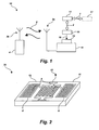
- FIG. 1 shows a schematic representation of the proximity sensing system 10 of an embodiment of the present invention.
- the transceiver 4 sends through its associated antenna 3b a request for information 5 about a position of an object.
- the request for information 5 sent by the transceiver 4 powers the SAW device, enabling it to operate wirelessly within the proximity sensing system 10.
- the wireless proximity sensing system 10 generally includes one or more first antennas 3a and one or more second antennas 3b.
- the first antenna 3a is associated with the proximity sensor for wirelessly receiving the request signal from the transceiver 4 and transmitting a response that includes information about a position of an object based on a location of the magnet 15 relative to the body 11 of the SAW device and relative to the sensing element 14.
- the second antenna 3b receives the information from the first antenna 3a and sends the information to the transceiver 4.
- the moveable target 17 is adapted and configured to act upon a magnet 15.
- the moveable target 17 is made of a ferromagnetic material with high magnetic permeability such as Iron, Cobalt, Nickel or any known equivalent in the art, and is further associated with the position of the object to be detected.
- the target 17 undergoes movement 2 as indicated by the dashed lines, relative to an object (not shown) whose position is to be determined by the sensing system 10.
- a change in the position of the magnet 15 is produced in response to the magnetic attraction between the target 17 and the magnet 15.
- the movement 6 of the magnet 15 can be constrained by an attaching member 16, such as an elastic rod, spring, elastic attaching member or biasing member.
- the magnet 15 enhances the magnetic field of the magnetostrictive material of the sensing element 14, which may be attached either during the masking process, by an adhesive or by other means for attaching known in the art to the body 11 of the SAW device.
- the sensing element 14 undergoes a mechanical response, which in turn produces a mechanical response in the body 11 of the SAW device to which it is attached.
- the change in the magnetic field of the magnetostrictive material of the sensing element 14 is characterized by a magnitude and/or phase shift.
- the pattern of changes of the relative difference between the neutral and changed magnetic fields, as expressed through the magnitude or phase shift, is the source of the information 5 of the position of an object (not shown), which is relayed to the antenna 3a back to antenna 3b, and subsequently received by the transceiver 4.
- the configuration of the SAW devices used in the wireless proximity sensor and sensing system according to the present invention may be any one of known SAW device configurations known in the art.
- these configurations may include building blocks such as micro-strip couplers, acoustic mirrors, and IDTs.
- the SAW device building blocks are identified as IDTs for simplicity.
- the IDTs of both configurations include electrodes made of magnetostrictive material such as TERFENOL-D, Galfenol, Cobalt, Nickel or any known equivalent in the art.
- One configuration of a SAW device according to the present invention is a basic 1-port SAW resonator 20 having a single IDT as depicted in FIG. 2 .
- a 2-port SAW sensor having multiple transducers, IDTs 12, 12a, and 12b may be used, as shown in FIG. 3 .
- the IDTs according to the present invention are adapted and configured to convert electromagnetic energy from one antenna into surface acoustic wave energy.
- FIG. 3 the propagation of SAW energy 9 through a sensing element 14, located on the surface of the SAW device 30 is shown.
- the IDTs 12a and 12b are further adapted and configured to convert surface acoustic wave energy 9 back into electromagnetic energy for transmission to one of the antennas 13a and 13b, information from which is eventually received by transceiver 4 of FIG. 1 .
- One of ordinary skill in the art would appreciate that the aforementioned electromagnetic energy and surface acoustic wave energy 9 contain either a request for or information about the position of an object.
- the 1- port SAW resonator configuration of FIG. 2 depicts a SAW device 20 having a body 11 formed of a substrate material having an upper surface, a lower surface, a first end and a second end.
- the SAW device 20 has only one IDT 12 provided on the upper surface of the body 11 with an associated antenna 13.
- the device 20 further comprises a sensing element (not shown) formed of magnetostrictive material deposited on the substrate material between the first end and the second end of the body 11.
- the SAW device 20 is further comprised of two grating reflectors 8 or mirrors, which reflect surface acoustic waves 9 and generate a standing wave between the two reflectors 8.
- the sensing element (not shown) is a thin film of magnetostrictive material deposited between the transducer 12 and at least one of the resonators 8 on the upper surface of the body 11.
- FIG. 3 An alternative 2-port SAW configuration, also known as a delay line, is shown in FIG. 3 and depicts a SAW device 30 having two IDTs 12a and 12b provided on the upper surface of the first end of the body 11 with associated antennas 13a and 13b respectively.
- the remaining figures utilize only one of the 2-port SAW device 30 configurations of Figure 3 .
- the present invention envisions the use of an array of either the single or multi port configurations.
- the 2-port SAW device 30 of FIG. 3 has a body 11 formed of a substrate material having an upper surface, a lower surface, a first end and a second end.
- the substrate material of the body 11 may be selected from any known piezoelectric single crystal material or piezoelectric on dielectric laminate material. Some substrate materials that may typically be used in the present invention are Quartz, LiNbO 3 , AlN, AlPO 4 , LiTaO 3 , Lagasite, Bi 4 Ge 3 O 12 (BGO), GaAs, PZT or any equivalent known in the art.
- the wireless proximity sensor and sensing system of Fig. 3 further include a SAW device 30 with a sensing element 14 formed of magnetostrictive material deposited on the substrate material between the first end and the second end.
- the location of the sensing element 14 may vary.
- the magnetostrictive material of the sensing element 14 may be deposited on the top surface as shown in FIG. 3 or attached to a side or bottom surface of the substrate material of the body 11.
- the magnetostrictive material of the sensing element 14 is typically made of TERFENOL-D, Galfenol, Cobalt, Nickel or any known equivalent in the art.
- the magnetostrictive material of the sensing element 14 may also vary in thickness, geometric shape and relative size in relation to the body 11.
- the magnetostrictive material may be a thin film or a block of bulk material with a long strip geometric shape.
- the block of bulk material of the sensing element 14 may be larger than the body 11, for example approximately twice the size of the body 11.
- the block of bulk material of the sensing element 14 may be smaller than the body 11, for example one-third of the size of the body 11.
- the size chosen is based on the desired mechanical response characteristics in order to maximize strain transfer on the sensing element 14.
- the wireless proximity sensor 40 of FIG. 4 shows a block of bulk magnetostrictive material of the sensing element 14 that is larger than the body 11 of the SAW device.
- FIG. 5 alternatively, shows a SAW device 50 having a block of bulk magnetostrictive material of the sensing element 14 that has smaller dimensions than that of the substrate material of the body 11.
- FIG. 5 further shows how the sensing element 14 and body 11 respond mechanically to the presence of a magnetic field, as indicated by the dashed lines.
- the right portion of the body 11 is illustrated in a bent position relative to the neutral position.
- the mechanical movement of the sensing element 14 is caused by the magnetic field induced by the magnet 15 (not shown) according to the present invention.
- the mechanical response of the sensing element 14 in turn causes a mechanical response of the body 11 of the SAW device.
- the response in the form of a phase or magnitude shift, is then translated to the transceiver 4 as information 5 about the position of an object relative to the target 17, as shown in FIG. 1 .
- the transceiver 4 is then translated to the transceiver 4 as information 5 about the position of an object relative to the target 17, as shown in FIG. 1 .
- only one magnet 15 is shown, one or more magnets 15 may be used.
- a wireless proximity sensor 40 of the present invention is shown in which the magnet 15 is operatively positioned with respect to the body 11 for providing a reference point of a position of an object.
- the magnet 15 is adapted and configured to induce a magnetic field in the sensing element 14.
- the magnet 15 is connected to the sensing element 14 by an attaching member 16, disposed between the magnet 15 and the sensing element 14.
- the magnet 15 is attached to a side surface of the sensing element 14.
- the magnet 15 may be attached to any one of a side, upper or lower surface of the sensing element 14 such that the magnet 15 and a surface of the sensing element 14 are connected.
- the magnet 15 is alternatively attached to the body 11.
- the elastic attaching member 16 allows for movement of the magnet 15 in relation to the sensing element 14.
- the elastic attaching member 16 may be an elastic rod, spring or coil as shown or any other biasing member known in the art.
- the movement of the magnet 15 can be one or more of horizontal, vertical, or rotational movement in relation to the sensing element 14, depending on the object position sensing application. As the magnet 15 moves closer to the sensing element 14, the attaching member 16 compresses, and the magnetic field in the sensing element 14 changes.
- the wireless proximity sensing system 60 may further include a movable target 17 operatively positioned to produce a change in the magnetic field induced in the sensing element 14 based on the movement 2 of the movable target 17 with respect to the magnet 15 according to yet another embodiment of the present invention.
- a movable target 17 is shown, one or more movable targets 17 may be used.
- the target 17 is made of a ferromagnetic material with a high magnetic permeability, such as Iron, Cobalt, Nickel or any equivalent known in the art.
- the target can either be a permanent magnet or a block of magnetic material. As the target 17 moves, the magnet 15 reacts which either compresses or decompresses the elastic member 16.
- stoppers 18 and 19 may be disposed between the target 17 and the magnet 15, between the magnet 15 and the elastic member 16, or between the elastic member 16 and the sensing element 14.
- the stoppers 18 and 19 are operatively positioned in order to limit the movement 6 of either the target 17 or the magnet 15 in relation to the sensing element 14.
- the range of mechanical response of the sensing element 14 and SAW body 11 can be manipulated as desired for a given proximity sensing application.
- the wireless proximity sensor and sensing system 70 may further includes a movable target 17.
- the target 17 can be operatively positioned, such that the sensing element 14 is disposed in between the magnet 15 and the target 17.
- the magnet 15 is shown in a u-shape, however, the magnet 15 can be any shape adapted and configured to interact with movable target 17.
- the target 17 is shown having a rectangular shape, however the target 17 can be any shape configured to interact with the magnet 15.
- Stopper 19 is also shown to be disposed between the elastic member 16 and the sensing element 14. The stopper 19 may be used to limit a desired movement 6 and compression of the elastic member 16 in response to the movement of the target 17.
Landscapes
- Measurement Of Length, Angles, Or The Like Using Electric Or Magnetic Means (AREA)
- Length Measuring Devices Characterised By Use Of Acoustic Means (AREA)
- Measurement Of Velocity Or Position Using Acoustic Or Ultrasonic Waves (AREA)
Abstract
Description
- The subject invention is related to proximity sensors for detection of a position of an object, and more particularly, to a wireless proximity sensor and sensing system that uses surface acoustic wave (SAW) technology to reduce weight and complexity to meet the rigorous demands of the aviation industry and other position sensing applications.
- Proximity sensors have long been used to indicate the position of an object on an aircraft or other vehicle (e.g., whether a door or hatch is open or closed). These proximity sensors are typically the current sensing induction type and heavily armored for isolation. The proximity sensor generates an electromagnetic field to sense metal objects passing within a few tenths of inches.
- The heavy isolation armor or shielding and wire required are highly undesirable in the field of weight sensitive aircraft design. By one estimate for fixed wing commercial aircraft, each extra pound has a recurring cost of over U.S. $500, a non-recurring cost of over U.S. $5000, and a life cycle cost of U.S. $100,000. For rotary wing craft (e.g., helicopters), the costs are typically twice that of fixed wing aircraft. Yet, a Boeing 787 airplane has approximately 150 proximity sensors with over 40 pounds of associated wire.
- While the aviation industry is looking for alternatives, the currently available options have their own disadvantages. One alternative is a voltage sensing capacitive type sensor, which may require heavy isolation hardware as a result of capacitive coupled voltage due to electromagnetic interference. Conductive fluids and water condensation pose additional problems for capacitive type sensors. Magnetic or optical interrupt switches, although much lighter due to less shielding, are failure prone in the harsh conditions of aviation. Further, magnetic switches attract ferrous metal filings that inhibit the detection of a near/far condition, resulting in false condition reporting and low reliability. Optical switches suffer from foreign object contamination, such as dirt, which again reduces the performance of the device. Further yet, each of these sensors uses hardwired connections to power and report state. Wire requires a number of aircraft interactions for installation that drives up cost in both design and manufacturability. Additionally, wire is heavy and difficult to troubleshoot when sensor operation fails.
- SAW devices having a magnetostrictive element are one type of electronic component that may be used to address the problems of weight sensitive proximity detection of objects in aircraft and other applications. Generally, SAW devices generate guided acoustic waves along a surface of the device. SAW devices are typically fabricated on single crystal anisotropic substrates that are also piezoelectric. SAW devices typically include one or more pairs of intertwined interdigital electrodes that form transducers (known as an interdigital transducer or IDT) to convert the electrical signals applied to the device into the electromechanical surface acoustic waves generated in the device and vice versa. However, SAW devices may also be present in different classes of acoustic devices such as micro-strip couplers and acoustic reflectors/mirrors etc., depending on the particular device configuration employed.
- One such SAW device is disclosed in
U.S. Patent No. 4,078,186 which discloses a magnetically tuned SAW device having a thin magnetostrictive film deposited only on the surface between its input and output transducers. A variable DC magnetic field is applied to the film by connecting the poles of an electromagnet to a DC supply. The electromagnet is then placed in line with the plane of the film to vary its magnetic field characteristics. A corresponding continuous variance in the delay or phase shift of the surface acoustic wave is produced thereby. This configuration however, has several drawbacks that do not make it ideal for proximity sensing applications. These drawbacks include, but are not limited to, the stationary positioning of the electromagnet and the weight of the wiring necessary to supply DC current to the poles of the electromagnet. - The present invention discloses a number of improvements over this and other known SAW devices and methods for proximity sensing, the features and advantages of which are described herein.
- The subject invention is directed to a wireless proximity sensor, wireless proximity sensing system, and method that uses SAW technology in conjunction with magnetostrictive materials to detect the position of objects. Such a sensor and sensing system is advantageous because it eliminates the need for heavy, complex and difficult to maintain sensors and sensor wiring. In addition, the device fabrication is simpler and requires fewer mask and processing steps with the added benefit of small proximity sensor device dimensions.
- A first embodiment of the wireless proximity sensor according to the present invention is a wireless proximity sensor for sensing the position of an object comprising a body formed of a substrate material having an upper surface, a lower surface, a first end and a second end. The sensor of this embodiment is further comprised of one or more IDTs provided on the upper surface of the first end of the body, wherein each of the IDTs has at least one associated antenna. However, other classes of SAW devices may be used such as micro-strip couplers and acoustic reflectors/mirrors. A sensing element formed of magnetostrictive material is also attached to or deposited on the substrate material. One or more magnets are further provided as well as one or more movable targets. The target, made of ferromagnetic material, is positioned to provide a reference point of the position of an object. The movement of the target acts upon the magnetic field of the magnet, which can be attached to any one of the surfaces of the sensing element or the SAW device body by an elastic attaching means disposed between the magnet and the sensing element. The means for attaching may include a biasing means such as an elastic rod or spring or other means known in the art. The magnet is therefore capable of movement with respect to the sensing element and the SAW device body. The resultant change in distance and position of the movement of the magnet relative to the sensing element induces a mechanical response in the sensing element(s) and the SAW device attached thereto, which provides information about the position of the object of which the desired position is to be detected.
- Various aspects and variations of the embodiments of the invention are further described below. The means for attaching of the first embodiment may include a biasing means such as an elastic rod, spring or the like. The substrate material of the body may be one of Quartz, LiNbO3, AlN, AlPO4, LiTaO3, Lagasite, Bi4Ge3O12 (BGO), GaAs, PZT or any equivalent known in the art. In addition, the magnetostrictive material of the sensing element may be selected from the group consisting of TERFENOL-D, Galfenol, Cobalt, and Nickel or any known equivalent thereof.
- The present invention also envisions variations on the geometry, thickness and location of the magnetostrictive material of the sensing element in relation to the sensor body. For example, the magnetostrictive material can be a thin film deposited on the upper surface of the substrate material between the first end and the second end of the body. Alternatively, the magnetostrictive material of the sensing element can be a block of bulk magnetostrictive material attached to the upper, lower, or side surfaces of the substrate material of the body. Further, the bulk material may be either larger or smaller than the sensing element depending upon the mechanical response of the sensing element desired due to the change in the magnetic field.
- The IDT discussed above is adapted and configured to convert electromagnetic energy from one of its associated antennas into surface acoustic wave energy for propagation through the sensing element. It is further adapted and configured to convert surface acoustic wave energy back into electromagnetic energy to the same or a different antenna to provide the object position information.
- A wireless proximity sensing system according to an embodiment of the present invention includes the wireless proximity sensor and various sensor embodiments described above, and further includes a transceiver such as a computer or a processor, for generating a query signal, which requests information about a position of an object from the proximity sensor device. The transceiver has one or more associated antennae that wirelessly receive information about the position of an object from the SAW device and also transmits a request for information to the SAW device and receives information from the SAW device.
- Those skilled in the art would readily appreciate that the components described above with respect to the proximity sensor also pertain to the proximity sensing system and method of the present invention.
- These and other aspects and advantages of the subject invention will become more readily apparent from the following description of the preferred embodiments taken in conjunction with the drawings.
- So that those skilled in the art to which the subject invention appertains will readily understand how to make and use the apparatus of subject invention without undue experimentation, preferred embodiments thereof will be described in detail herein below with reference to certain figures, wherein:
-
FIG. 1 shows a schematic representation of the proximity sensing system of the present invention; -
FIG. 2 shows a SAW device having a single IDT and two acoustic reflectors used within a wireless proximity sensor according to an embodiment of the present invention; -
FIG. 3 shows a SAW device having multiple IDTs used within the proximity sensor according to an embodiment of the present invention; -
FIG. 4 shows a wireless proximity sensor having a magnet connected to the substrate by an elastic member according to an embodiment of the present invention; -
FIG. 5 shows a SAW device having a sensing element made of a block of bulk magnetostrictive material attached according to an embodiment of the present invention; -
FIG. 6 shows a wireless proximity sensor according to an embodiment of the present invention having a movable target; and -
FIG. 7 shows a wireless proximity sensor according to an embodiment of the present invention having a movable target with optional stoppers inserted between the elastic member and the sensing element. - The subject invention relates to a wireless proximity sensor, system and method for detecting the presence of both moving and stationary objects.
FIG. 1 shows a schematic representation of theproximity sensing system 10 of an embodiment of the present invention. The transceiver 4 sends through its associatedantenna 3b a request forinformation 5 about a position of an object. The request forinformation 5 sent by the transceiver 4 powers the SAW device, enabling it to operate wirelessly within theproximity sensing system 10. - The wireless
proximity sensing system 10 generally includes one or morefirst antennas 3a and one or moresecond antennas 3b. Thefirst antenna 3a is associated with the proximity sensor for wirelessly receiving the request signal from the transceiver 4 and transmitting a response that includes information about a position of an object based on a location of themagnet 15 relative to thebody 11 of the SAW device and relative to thesensing element 14. Thesecond antenna 3b receives the information from thefirst antenna 3a and sends the information to the transceiver 4. - Those skilled in the art would readily appreciate that the
moveable target 17 is adapted and configured to act upon amagnet 15. Themoveable target 17 is made of a ferromagnetic material with high magnetic permeability such as Iron, Cobalt, Nickel or any known equivalent in the art, and is further associated with the position of the object to be detected. Thetarget 17 undergoesmovement 2 as indicated by the dashed lines, relative to an object (not shown) whose position is to be determined by thesensing system 10. As a result, a change in the position of themagnet 15 is produced in response to the magnetic attraction between thetarget 17 and themagnet 15. Themovement 6 of themagnet 15 can be constrained by an attachingmember 16, such as an elastic rod, spring, elastic attaching member or biasing member. Themagnet 15 enhances the magnetic field of the magnetostrictive material of thesensing element 14, which may be attached either during the masking process, by an adhesive or by other means for attaching known in the art to thebody 11 of the SAW device. - Due to the shift in the magnetic field, the
sensing element 14 undergoes a mechanical response, which in turn produces a mechanical response in thebody 11 of the SAW device to which it is attached. The change in the magnetic field of the magnetostrictive material of thesensing element 14 is characterized by a magnitude and/or phase shift. The pattern of changes of the relative difference between the neutral and changed magnetic fields, as expressed through the magnitude or phase shift, is the source of theinformation 5 of the position of an object (not shown), which is relayed to theantenna 3a back toantenna 3b, and subsequently received by the transceiver 4. - The configuration of the SAW devices used in the wireless proximity sensor and sensing system according to the present invention may be any one of known SAW device configurations known in the art. Conventionally, these configurations may include building blocks such as micro-strip couplers, acoustic mirrors, and IDTs. Here, the SAW device building blocks are identified as IDTs for simplicity. The IDTs of both configurations include electrodes made of magnetostrictive material such as TERFENOL-D, Galfenol, Cobalt, Nickel or any known equivalent in the art.
- One configuration of a SAW device according to the present invention is a basic 1-
port SAW resonator 20 having a single IDT as depicted inFIG. 2 . Alternatively, a 2-port SAW sensor having multiple transducers,IDTs FIG. 3 . The IDTs according to the present invention are adapted and configured to convert electromagnetic energy from one antenna into surface acoustic wave energy. InFIG. 3 , the propagation ofSAW energy 9 through asensing element 14, located on the surface of theSAW device 30 is shown. TheIDTs acoustic wave energy 9 back into electromagnetic energy for transmission to one of theantennas FIG. 1 . One of ordinary skill in the art would appreciate that the aforementioned electromagnetic energy and surfaceacoustic wave energy 9 contain either a request for or information about the position of an object. - The 1- port SAW resonator configuration of
FIG. 2 depicts aSAW device 20 having abody 11 formed of a substrate material having an upper surface, a lower surface, a first end and a second end. TheSAW device 20 has only oneIDT 12 provided on the upper surface of thebody 11 with an associatedantenna 13. Thedevice 20 further comprises a sensing element (not shown) formed of magnetostrictive material deposited on the substrate material between the first end and the second end of thebody 11. In the single transducer configuration ofFIG. 2 , theSAW device 20 is further comprised of twograting reflectors 8 or mirrors, which reflect surfaceacoustic waves 9 and generate a standing wave between the tworeflectors 8. In this embodiment, the sensing element (not shown) is a thin film of magnetostrictive material deposited between thetransducer 12 and at least one of theresonators 8 on the upper surface of thebody 11. - An alternative 2-port SAW configuration, also known as a delay line, is shown in
FIG. 3 and depicts aSAW device 30 having twoIDTs body 11 with associatedantennas port SAW device 30 configurations ofFigure 3 . However, it is to be understood that the present invention envisions the use of an array of either the single or multi port configurations. Like the 1- port SAW resonator configuration, the 2-port SAW device 30 ofFIG. 3 has abody 11 formed of a substrate material having an upper surface, a lower surface, a first end and a second end. The substrate material of thebody 11 may be selected from any known piezoelectric single crystal material or piezoelectric on dielectric laminate material. Some substrate materials that may typically be used in the present invention are Quartz, LiNbO3, AlN, AlPO4, LiTaO3, Lagasite, Bi4Ge3O12 (BGO), GaAs, PZT or any equivalent known in the art. - The wireless proximity sensor and sensing system of
Fig. 3 further include aSAW device 30 with asensing element 14 formed of magnetostrictive material deposited on the substrate material between the first end and the second end. The location of thesensing element 14 may vary. For example, the magnetostrictive material of thesensing element 14 may be deposited on the top surface as shown inFIG. 3 or attached to a side or bottom surface of the substrate material of thebody 11. The magnetostrictive material of thesensing element 14 is typically made of TERFENOL-D, Galfenol, Cobalt, Nickel or any known equivalent in the art. - The magnetostrictive material of the
sensing element 14 may also vary in thickness, geometric shape and relative size in relation to thebody 11. With regard to thickness, the magnetostrictive material may be a thin film or a block of bulk material with a long strip geometric shape. The block of bulk material of thesensing element 14 may be larger than thebody 11, for example approximately twice the size of thebody 11. Alternatively, the block of bulk material of thesensing element 14 may be smaller than thebody 11, for example one-third of the size of thebody 11. The size chosen is based on the desired mechanical response characteristics in order to maximize strain transfer on thesensing element 14. Thewireless proximity sensor 40 ofFIG. 4 shows a block of bulk magnetostrictive material of thesensing element 14 that is larger than thebody 11 of the SAW device. -
FIG. 5 , alternatively, shows aSAW device 50 having a block of bulk magnetostrictive material of thesensing element 14 that has smaller dimensions than that of the substrate material of thebody 11.FIG. 5 further shows how thesensing element 14 andbody 11 respond mechanically to the presence of a magnetic field, as indicated by the dashed lines. The right portion of thebody 11 is illustrated in a bent position relative to the neutral position. The mechanical movement of thesensing element 14 is caused by the magnetic field induced by the magnet 15 (not shown) according to the present invention. The mechanical response of thesensing element 14 in turn causes a mechanical response of thebody 11 of the SAW device. The response, in the form of a phase or magnitude shift, is then translated to the transceiver 4 asinformation 5 about the position of an object relative to thetarget 17, as shown inFIG. 1 . Although only onemagnet 15 is shown, one ormore magnets 15 may be used. - Turning again to
FIG. 4 , awireless proximity sensor 40 of the present invention is shown in which themagnet 15 is operatively positioned with respect to thebody 11 for providing a reference point of a position of an object. As discussed above, themagnet 15 is adapted and configured to induce a magnetic field in thesensing element 14. Themagnet 15 is connected to thesensing element 14 by an attachingmember 16, disposed between themagnet 15 and thesensing element 14. Here, themagnet 15 is attached to a side surface of thesensing element 14. However, themagnet 15 may be attached to any one of a side, upper or lower surface of thesensing element 14 such that themagnet 15 and a surface of thesensing element 14 are connected. In another embodiment, themagnet 15 is alternatively attached to thebody 11. The elastic attachingmember 16 allows for movement of themagnet 15 in relation to thesensing element 14. The elastic attachingmember 16 may be an elastic rod, spring or coil as shown or any other biasing member known in the art. The movement of themagnet 15 can be one or more of horizontal, vertical, or rotational movement in relation to thesensing element 14, depending on the object position sensing application. As themagnet 15 moves closer to thesensing element 14, the attachingmember 16 compresses, and the magnetic field in thesensing element 14 changes. - Referring to
FIG. 6 , there is shown an embodiment in which the wirelessproximity sensing system 60 may further include amovable target 17 operatively positioned to produce a change in the magnetic field induced in thesensing element 14 based on themovement 2 of themovable target 17 with respect to themagnet 15 according to yet another embodiment of the present invention. Although only onemovable target 17 is shown, one or moremovable targets 17 may be used. Thetarget 17 is made of a ferromagnetic material with a high magnetic permeability, such as Iron, Cobalt, Nickel or any equivalent known in the art. In addition, the target can either be a permanent magnet or a block of magnetic material. As thetarget 17 moves, themagnet 15 reacts which either compresses or decompresses theelastic member 16. In one embodiment,stoppers target 17 and themagnet 15, between themagnet 15 and theelastic member 16, or between theelastic member 16 and thesensing element 14. Thestoppers movement 6 of either thetarget 17 or themagnet 15 in relation to thesensing element 14. By limiting the range inmovement 6 of themagnet 15, the range of mechanical response of thesensing element 14 andSAW body 11 can be manipulated as desired for a given proximity sensing application. - Referring to
FIG. 7 , there is shown an additional embodiment in which the wireless proximity sensor andsensing system 70 may further includes amovable target 17. Thetarget 17 can be operatively positioned, such that thesensing element 14 is disposed in between themagnet 15 and thetarget 17. Themagnet 15 is shown in a u-shape, however, themagnet 15 can be any shape adapted and configured to interact withmovable target 17. Further, thetarget 17 is shown having a rectangular shape, however thetarget 17 can be any shape configured to interact with themagnet 15.Stopper 19 is also shown to be disposed between theelastic member 16 and thesensing element 14. Thestopper 19 may be used to limit a desiredmovement 6 and compression of theelastic member 16 in response to the movement of thetarget 17. - Although the subject invention has been described with respect to preferred embodiments, those skilled in the art will readily appreciated that changes or modifications thereto may be made without departing from the spirit or scope of the subject invention as defined by the appended claims.
Claims (16)
- A wireless proximity sensor for sensing the position of an object comprising:a) a body formed of a substrate material having an upper surface, a lower surface, a first end and a second end;b) at least one interdigital transducer provided on a surface of the body, wherein each of the at least one interdigital transducers has at least one first antenna associated therewith;c) at least one sensing element formed of magnetostrictive material provided on the substrate material;d) at least one magnet operatively positioned with respect to the body for providing a reference point of a position of an object, wherein the at least one magnet is adapted and configured to induce a magnetic field in the at least one sensing element; ande) a means for attaching disposed between the at least one magnet and a first side surface of the at least one sensing element, such that the at least one magnet and the first side surface of the at least one sensing element are connected, allowing for movement of the at least one magnet in relation to the at least one sensing element.
- A wireless proximity sensor as recited in claim 1, wherein the means for attaching is an biasing means for biasing the sensing element relative to the at least one magnet.
- A wireless proximity sensor as recited in claim 1 or 2, wherein the substrate material of the body is selected from the group consisting of Quartz, LiNbO3, AIN, AlPO4, LiTaO3, Lagasite, Bi4Ge3O12 (BGO), GaAs and PZT.
- A wireless proximity sensor as recited in any of the preceding claims, wherein the magnetostrictive material of the at least one sensing element is selected from the group consisting of TERFENOL-D, Galfenol, Cobalt, and Nickel.
- A wireless proximity sensor as recited in any of the preceding claims, wherein the at least one transducer is adapted and configured to convert electromagnetic energy from the at least one first antenna into surface acoustic wave energy for propagation through the at least one sensing element and further adapted and configured to convert surface acoustic wave energy back into electromagnetic energy to the at least one first antenna.
- A wireless proximity sensor as recited in claim 5, further comprising at least one movable target operatively positioned to produce a change in the magnetic field induced in the at least one sensing element based on the movement of the at least one movable target with respect to the at least one magnet.
- A wireless proximity sensor as recited in claim 5, wherein the magnetostrictive material of the at least one sensing element is a thin film of magnetostrictive material deposited on the upper surface of the substrate material between the first end and the second end of the body.
- A wireless proximity sensor as recited in claim 5, wherein the magnetostrictive material of the at least one sensing element is a block of bulk magnetostrictive material attached to the substrate material.
- A wireless proximity sensor as recited in claim 8, wherein the block of bulk magnetostrictive material is larger than the body.
- A wireless proximity sensor as recited in claim 8, wherein the block of bulk magnetostrictive material is smaller than the body.
- A wireless proximity sensor as recited in any of the preceding claims, comprising:a transceiver adapted and configured to generate a query signal to request information about a position of an object; anda second antenna for wirelessly receiving information about a position of an object from and transmitting information to the transceiver to the at least one first antenna.
- A method for wirelessly detecting the position of an object comprising:a) providing at least one SAW device having a sensing element adapted to produce a mechanical response in the at least one SAW device in response to a change in a magnetic field of the sensing element;b) providing at least one magnet movable relative to the sensing element and adapted to produce a change in the magnetic field of the sensing element based on movement of the at least one magnet;c) positioning at least one moveable target relative to the object so that movement of the at least one moveable target causes movement in the at least one magnet;d) wirelessly powering the at least one SAW device; ande) detecting information indicative of the mechanical response in the at least one SAW device relative to a change in the magnetic field of the sensing element, indicating the position of the object.
- The method according to claim 12, wherein the step of detecting information indicative of the mechanical response, is further based on movement of the at least one magnet in response to movement of the at least one moveable target.
- The method of claim 12 or 13, wherein the step of providing at least one magnet, further comprises the step of attaching the at least one magnet to the at least one SAW device and sensing element.
- The method of any of claims 12 to 14, wherein the step of wirelessly powering the at least one SAW device further includes the step of sending a request for information indicative of a position of the at least one moveable target relative to the object from a transceiver.
- The method of claim 15, further comprising wirelessly transmitting the information detected indicating the position of the object to the transceiver.
Applications Claiming Priority (1)
| Application Number | Priority Date | Filing Date | Title |
|---|---|---|---|
| US11/977,301 US7834514B2 (en) | 2007-10-24 | 2007-10-24 | Wireless surface acoustic wave-based proximity sensor, sensing system and method |
Publications (3)
| Publication Number | Publication Date |
|---|---|
| EP2053743A2 true EP2053743A2 (en) | 2009-04-29 |
| EP2053743A3 EP2053743A3 (en) | 2011-05-25 |
| EP2053743B1 EP2053743B1 (en) | 2012-03-07 |
Family
ID=40291053
Family Applications (1)
| Application Number | Title | Priority Date | Filing Date |
|---|---|---|---|
| EP08018238A Not-in-force EP2053743B1 (en) | 2007-10-24 | 2008-10-17 | Wireless surface acoustic wave-based proximity sensor, sensing system and method |
Country Status (5)
| Country | Link |
|---|---|
| US (1) | US7834514B2 (en) |
| EP (1) | EP2053743B1 (en) |
| AT (1) | ATE548801T1 (en) |
| BR (1) | BRPI0804527A2 (en) |
| CA (1) | CA2640918A1 (en) |
Cited By (2)
| Publication number | Priority date | Publication date | Assignee | Title |
|---|---|---|---|---|
| WO2011154157A1 (en) * | 2010-06-10 | 2011-12-15 | Abb Technology Ag | Wireless current measuring device |
| WO2019201409A1 (en) * | 2018-04-19 | 2019-10-24 | Diehl Ako Stiftung & Co. Kg | Push button operating device |
Families Citing this family (18)
| Publication number | Priority date | Publication date | Assignee | Title |
|---|---|---|---|---|
| US7683521B2 (en) * | 2006-12-05 | 2010-03-23 | Simmonds Precision Products, Inc. | Radio frequency surface acoustic wave proximity detector |
| US8269490B2 (en) * | 2009-04-03 | 2012-09-18 | Honeywell International Inc. | Magnetic surface acoustic wave sensor apparatus and method |
| DE102009038781B4 (en) * | 2009-08-25 | 2015-05-21 | Airbus Operations Gmbh | Device for the premature detection of the closing state of a closure element for a space opening, closure device for a cargo hold of an aircraft, use and aircraft |
| US8669871B2 (en) | 2009-11-13 | 2014-03-11 | University Of Central Florida Research Foundation, Inc. | Implementation of on-off passive wireless surface acoustic wave sensor using coding and switching techniques |
| US9768888B2 (en) * | 2013-10-31 | 2017-09-19 | King Abdullah University Of Science And Technology | Integrated passive and wireless sensor |
| KR101616639B1 (en) * | 2014-11-11 | 2016-04-28 | 삼성전기주식회사 | Surface acoustic device and apparatus having the suface acoustic device, and detection sensor using the apparatus |
| JP6720416B2 (en) * | 2016-08-31 | 2020-07-08 | ホアウェイ・テクノロジーズ・デュッセルドルフ・ゲーエムベーハー | Filtered multi-carrier communication |
| US11239823B1 (en) | 2017-06-16 | 2022-02-01 | Hrl Laboratories, Llc | Quartz MEMS piezoelectric resonator for chipscale RF antennae |
| US11101786B1 (en) | 2017-06-20 | 2021-08-24 | Hrl Laboratories, Llc | HF-VHF quartz MEMS resonator |
| US10921360B2 (en) * | 2018-02-09 | 2021-02-16 | Hrl Laboratories, Llc | Dual magnetic and electric field quartz sensor |
| CN108470825B (en) * | 2018-03-28 | 2019-11-05 | 电子科技大学 | Magnetoelectricity SAW device based on negative poisson's ratio magnetostriction substrate |
| US10600438B2 (en) * | 2018-04-18 | 2020-03-24 | Seagate Technology Llc | Surface acoustic wave-based sensing and actuation of contamination |
| US10819276B1 (en) | 2018-05-31 | 2020-10-27 | Hrl Laboratories, Llc | Broadband integrated RF magnetic antenna |
| US11563420B1 (en) | 2019-03-29 | 2023-01-24 | Hrl Laboratories, Llc | Femto-tesla MEMS RF antenna with integrated flux concentrator |
| US11988727B1 (en) | 2019-07-31 | 2024-05-21 | Hrl Laboratories, Llc | Magnetostrictive MEMS magnetic gradiometer |
| CN114034406B (en) * | 2021-11-08 | 2024-05-28 | 株洲国创轨道科技有限公司 | Magnetostrictive high-energy excited low-frequency surface acoustic wave sensor |
| CN116315618B (en) * | 2023-05-08 | 2023-10-31 | 安徽大学 | Miniaturized multi-beam low-frequency/5G/6G continuous frequency adjustable antenna |
| GB2644112A (en) * | 2024-09-17 | 2026-03-18 | Univ Warwick | Probe |
Citations (1)
| Publication number | Priority date | Publication date | Assignee | Title |
|---|---|---|---|---|
| US4078186A (en) | 1976-10-21 | 1978-03-07 | The United States Of America As Represented By The Secretary Of The Navy | Magnetically tuned, surface acoustic wave device |
Family Cites Families (11)
| Publication number | Priority date | Publication date | Assignee | Title |
|---|---|---|---|---|
| DE19514342C1 (en) * | 1995-04-18 | 1996-02-22 | Siemens Ag | Radio-interrogated current transducer for HV or MV appts. |
| US7880594B2 (en) * | 2000-09-08 | 2011-02-01 | Automotive Technologies International, Inc. | Switch assemblies and method for controlling vehicular components |
| AT405981B (en) * | 1998-07-31 | 2000-01-25 | Hoerbiger Ventilwerke Gmbh | WEAR MONITOR |
| IL127699A0 (en) * | 1998-12-23 | 1999-10-28 | Bar Dov Aharon | Method and device for non contact detection of external electric or magnetic fields |
| DE10010846A1 (en) * | 2000-03-06 | 2001-09-20 | Siemens Ag | Appliance for determining measured variables corresponding to reactive resistance of sensor connected to surface acoustic wave (SAW) element matching network |
| DE10047343B4 (en) * | 2000-09-25 | 2004-04-15 | Siemens Ag | resonator |
| JP2004032052A (en) * | 2002-06-21 | 2004-01-29 | Canon Inc | Image processing system and system |
| JP2004215389A (en) * | 2002-12-27 | 2004-07-29 | Victor Co Of Japan Ltd | Surface acoustic wave actuator and deflector employing surface acoustic wave actuator |
| JP2008515043A (en) * | 2004-09-27 | 2008-05-08 | コーニンクレッカ フィリップス エレクトロニクス エヌ ヴィ | Magnetic sensor for input device |
| JP2007018492A (en) * | 2005-06-06 | 2007-01-25 | Fuji Xerox Co Ltd | Wireless response device, image forming apparatus, and equipment |
| DE102005039662A1 (en) * | 2005-08-22 | 2007-03-22 | Asm Automation Sensorik Messtechnik Gmbh | position sensor |
-
2007
- 2007-10-24 US US11/977,301 patent/US7834514B2/en not_active Expired - Fee Related
-
2008
- 2008-10-10 CA CA002640918A patent/CA2640918A1/en not_active Abandoned
- 2008-10-17 AT AT08018238T patent/ATE548801T1/en active
- 2008-10-17 EP EP08018238A patent/EP2053743B1/en not_active Not-in-force
- 2008-10-23 BR BRPI0804527-5A patent/BRPI0804527A2/en not_active Application Discontinuation
Patent Citations (1)
| Publication number | Priority date | Publication date | Assignee | Title |
|---|---|---|---|---|
| US4078186A (en) | 1976-10-21 | 1978-03-07 | The United States Of America As Represented By The Secretary Of The Navy | Magnetically tuned, surface acoustic wave device |
Cited By (3)
| Publication number | Priority date | Publication date | Assignee | Title |
|---|---|---|---|---|
| WO2011154157A1 (en) * | 2010-06-10 | 2011-12-15 | Abb Technology Ag | Wireless current measuring device |
| EP2400308A1 (en) * | 2010-06-10 | 2011-12-28 | ABB Technology AG | Wireless current measuring device |
| WO2019201409A1 (en) * | 2018-04-19 | 2019-10-24 | Diehl Ako Stiftung & Co. Kg | Push button operating device |
Also Published As
| Publication number | Publication date |
|---|---|
| EP2053743B1 (en) | 2012-03-07 |
| CA2640918A1 (en) | 2009-04-24 |
| US7834514B2 (en) | 2010-11-16 |
| ATE548801T1 (en) | 2012-03-15 |
| BRPI0804527A2 (en) | 2009-06-30 |
| EP2053743A3 (en) | 2011-05-25 |
| US20090109048A1 (en) | 2009-04-30 |
Similar Documents
| Publication | Publication Date | Title |
|---|---|---|
| US7834514B2 (en) | Wireless surface acoustic wave-based proximity sensor, sensing system and method | |
| US11151337B2 (en) | Low loss acoustic wave sensors and tags and high efficiency antennas and methods for remote activation thereof | |
| EP0781994B1 (en) | Electromagnetic acoustic transducer and emar system | |
| US6109108A (en) | Electromagnetic acoustic transducer EMAT and inspection system with EMAR | |
| CN1181814A (en) | Wireless Q&A Surface Wave Technology Sensors | |
| CN101952695B (en) | Device for improved response when measuring vibration frequency of a vibrating object | |
| JP3883211B2 (en) | Device for measuring the impedance of resonant structures | |
| CN114942444B (en) | A wireless passive flexible surface acoustic wave ice sensor | |
| CN101644772A (en) | Acoustic surface wave icing sensor capable of accessing wirelessly | |
| US6046657A (en) | Magnetostrictive surface acoustic wave device and microelectronic circuit including same | |
| CN107014325A (en) | A kind of wireless passive sonic surface wave strain transducer | |
| Kino et al. | Signal processing in acoustic surface-wave devices | |
| CN105890789A (en) | Thermometer And Measuring Device For Fluids | |
| US10648868B2 (en) | Surface acoustic wave device | |
| Ibrahim et al. | A ferrous-selective proximity sensor for industrial internet of things | |
| Joshi et al. | SH acoustic waves in a lithium niobate plate and the effect of electrical boundary conditions on their properties | |
| CN111650447B (en) | Surface acoustic wave solid-state electric field sensor | |
| Bruckner et al. | SAW delay lines as wireless sensors for industrial applications | |
| RU2758341C1 (en) | Passive wireless sensor of magnetic field on surface acoustic waves | |
| US7683521B2 (en) | Radio frequency surface acoustic wave proximity detector | |
| TW202006515A (en) | A proximity sensor and proximity sensing method | |
| US20050198948A1 (en) | Temperature-supervised hydrodynamic machine | |
| US8237545B2 (en) | Wireless transponder and image forming device | |
| US2973504A (en) | Sonic echo system | |
| RU2254595C2 (en) | Radio transponder sensor of location and orientation (variants) |
Legal Events
| Date | Code | Title | Description |
|---|---|---|---|
| PUAI | Public reference made under article 153(3) epc to a published international application that has entered the european phase |
Free format text: ORIGINAL CODE: 0009012 |
|
| AK | Designated contracting states |
Kind code of ref document: A2 Designated state(s): AT BE BG CH CY CZ DE DK EE ES FI FR GB GR HR HU IE IS IT LI LT LU LV MC MT NL NO PL PT RO SE SI SK TR |
|
| AX | Request for extension of the european patent |
Extension state: AL BA MK RS |
|
| PUAL | Search report despatched |
Free format text: ORIGINAL CODE: 0009013 |
|
| AK | Designated contracting states |
Kind code of ref document: A3 Designated state(s): AT BE BG CH CY CZ DE DK EE ES FI FR GB GR HR HU IE IS IT LI LT LU LV MC MT NL NO PL PT RO SE SI SK TR |
|
| AX | Request for extension of the european patent |
Extension state: AL BA MK RS |
|
| GRAC | Information related to communication of intention to grant a patent modified |
Free format text: ORIGINAL CODE: EPIDOSCIGR1 |
|
| GRAP | Despatch of communication of intention to grant a patent |
Free format text: ORIGINAL CODE: EPIDOSNIGR1 |
|
| GRAC | Information related to communication of intention to grant a patent modified |
Free format text: ORIGINAL CODE: EPIDOSCIGR1 |
|
| 17P | Request for examination filed |
Effective date: 20110610 |
|
| RIC1 | Information provided on ipc code assigned before grant |
Ipc: H03K 17/97 20060101ALI20110630BHEP Ipc: H03K 17/95 20060101AFI20110630BHEP |
|
| GRAS | Grant fee paid |
Free format text: ORIGINAL CODE: EPIDOSNIGR3 |
|
| AKX | Designation fees paid |
Designated state(s): AT BE BG CH CY CZ DE DK EE ES FI FR GB GR HR HU IE IS IT LI LT LU LV MC MT NL NO PL PT RO SE SI SK TR |
|
| GRAA | (expected) grant |
Free format text: ORIGINAL CODE: 0009210 |
|
| AK | Designated contracting states |
Kind code of ref document: B1 Designated state(s): AT BE BG CH CY CZ DE DK EE ES FI FR GB GR HR HU IE IS IT LI LT LU LV MC MT NL NO PL PT RO SE SI SK TR |
|
| REG | Reference to a national code |
Ref country code: GB Ref legal event code: FG4D |
|
| REG | Reference to a national code |
Ref country code: AT Ref legal event code: REF Ref document number: 548801 Country of ref document: AT Kind code of ref document: T Effective date: 20120315 Ref country code: CH Ref legal event code: EP |
|
| REG | Reference to a national code |
Ref country code: IE Ref legal event code: FG4D |
|
| REG | Reference to a national code |
Ref country code: DE Ref legal event code: R096 Ref document number: 602008013863 Country of ref document: DE Effective date: 20120426 |
|
| REG | Reference to a national code |
Ref country code: NL Ref legal event code: VDEP Effective date: 20120307 |
|
| PG25 | Lapsed in a contracting state [announced via postgrant information from national office to epo] |
Ref country code: NO Free format text: LAPSE BECAUSE OF FAILURE TO SUBMIT A TRANSLATION OF THE DESCRIPTION OR TO PAY THE FEE WITHIN THE PRESCRIBED TIME-LIMIT Effective date: 20120607 Ref country code: HR Free format text: LAPSE BECAUSE OF FAILURE TO SUBMIT A TRANSLATION OF THE DESCRIPTION OR TO PAY THE FEE WITHIN THE PRESCRIBED TIME-LIMIT Effective date: 20120307 Ref country code: LT Free format text: LAPSE BECAUSE OF FAILURE TO SUBMIT A TRANSLATION OF THE DESCRIPTION OR TO PAY THE FEE WITHIN THE PRESCRIBED TIME-LIMIT Effective date: 20120307 Ref country code: NL Free format text: LAPSE BECAUSE OF FAILURE TO SUBMIT A TRANSLATION OF THE DESCRIPTION OR TO PAY THE FEE WITHIN THE PRESCRIBED TIME-LIMIT Effective date: 20120307 |
|
| LTIE | Lt: invalidation of european patent or patent extension |
Effective date: 20120307 |
|
| PG25 | Lapsed in a contracting state [announced via postgrant information from national office to epo] |
Ref country code: LV Free format text: LAPSE BECAUSE OF FAILURE TO SUBMIT A TRANSLATION OF THE DESCRIPTION OR TO PAY THE FEE WITHIN THE PRESCRIBED TIME-LIMIT Effective date: 20120307 Ref country code: GR Free format text: LAPSE BECAUSE OF FAILURE TO SUBMIT A TRANSLATION OF THE DESCRIPTION OR TO PAY THE FEE WITHIN THE PRESCRIBED TIME-LIMIT Effective date: 20120608 Ref country code: FI Free format text: LAPSE BECAUSE OF FAILURE TO SUBMIT A TRANSLATION OF THE DESCRIPTION OR TO PAY THE FEE WITHIN THE PRESCRIBED TIME-LIMIT Effective date: 20120307 |
|
| REG | Reference to a national code |
Ref country code: AT Ref legal event code: MK05 Ref document number: 548801 Country of ref document: AT Kind code of ref document: T Effective date: 20120307 |
|
| PG25 | Lapsed in a contracting state [announced via postgrant information from national office to epo] |
Ref country code: CY Free format text: LAPSE BECAUSE OF FAILURE TO SUBMIT A TRANSLATION OF THE DESCRIPTION OR TO PAY THE FEE WITHIN THE PRESCRIBED TIME-LIMIT Effective date: 20120307 |
|
| PG25 | Lapsed in a contracting state [announced via postgrant information from national office to epo] |
Ref country code: CZ Free format text: LAPSE BECAUSE OF FAILURE TO SUBMIT A TRANSLATION OF THE DESCRIPTION OR TO PAY THE FEE WITHIN THE PRESCRIBED TIME-LIMIT Effective date: 20120307 Ref country code: IS Free format text: LAPSE BECAUSE OF FAILURE TO SUBMIT A TRANSLATION OF THE DESCRIPTION OR TO PAY THE FEE WITHIN THE PRESCRIBED TIME-LIMIT Effective date: 20120707 Ref country code: BE Free format text: LAPSE BECAUSE OF FAILURE TO SUBMIT A TRANSLATION OF THE DESCRIPTION OR TO PAY THE FEE WITHIN THE PRESCRIBED TIME-LIMIT Effective date: 20120307 Ref country code: EE Free format text: LAPSE BECAUSE OF FAILURE TO SUBMIT A TRANSLATION OF THE DESCRIPTION OR TO PAY THE FEE WITHIN THE PRESCRIBED TIME-LIMIT Effective date: 20120307 Ref country code: PL Free format text: LAPSE BECAUSE OF FAILURE TO SUBMIT A TRANSLATION OF THE DESCRIPTION OR TO PAY THE FEE WITHIN THE PRESCRIBED TIME-LIMIT Effective date: 20120307 Ref country code: SE Free format text: LAPSE BECAUSE OF FAILURE TO SUBMIT A TRANSLATION OF THE DESCRIPTION OR TO PAY THE FEE WITHIN THE PRESCRIBED TIME-LIMIT Effective date: 20120307 Ref country code: RO Free format text: LAPSE BECAUSE OF FAILURE TO SUBMIT A TRANSLATION OF THE DESCRIPTION OR TO PAY THE FEE WITHIN THE PRESCRIBED TIME-LIMIT Effective date: 20120307 Ref country code: SI Free format text: LAPSE BECAUSE OF FAILURE TO SUBMIT A TRANSLATION OF THE DESCRIPTION OR TO PAY THE FEE WITHIN THE PRESCRIBED TIME-LIMIT Effective date: 20120307 |
|
| PG25 | Lapsed in a contracting state [announced via postgrant information from national office to epo] |
Ref country code: SK Free format text: LAPSE BECAUSE OF FAILURE TO SUBMIT A TRANSLATION OF THE DESCRIPTION OR TO PAY THE FEE WITHIN THE PRESCRIBED TIME-LIMIT Effective date: 20120307 Ref country code: PT Free format text: LAPSE BECAUSE OF FAILURE TO SUBMIT A TRANSLATION OF THE DESCRIPTION OR TO PAY THE FEE WITHIN THE PRESCRIBED TIME-LIMIT Effective date: 20120709 |
|
| PLBE | No opposition filed within time limit |
Free format text: ORIGINAL CODE: 0009261 |
|
| STAA | Information on the status of an ep patent application or granted ep patent |
Free format text: STATUS: NO OPPOSITION FILED WITHIN TIME LIMIT |
|
| PG25 | Lapsed in a contracting state [announced via postgrant information from national office to epo] |
Ref country code: DK Free format text: LAPSE BECAUSE OF FAILURE TO SUBMIT A TRANSLATION OF THE DESCRIPTION OR TO PAY THE FEE WITHIN THE PRESCRIBED TIME-LIMIT Effective date: 20120307 Ref country code: AT Free format text: LAPSE BECAUSE OF FAILURE TO SUBMIT A TRANSLATION OF THE DESCRIPTION OR TO PAY THE FEE WITHIN THE PRESCRIBED TIME-LIMIT Effective date: 20120307 |
|
| PGFP | Annual fee paid to national office [announced via postgrant information from national office to epo] |
Ref country code: FR Payment date: 20121107 Year of fee payment: 5 Ref country code: DE Payment date: 20121029 Year of fee payment: 5 |
|
| 26N | No opposition filed |
Effective date: 20121210 |
|
| PG25 | Lapsed in a contracting state [announced via postgrant information from national office to epo] |
Ref country code: IT Free format text: LAPSE BECAUSE OF FAILURE TO SUBMIT A TRANSLATION OF THE DESCRIPTION OR TO PAY THE FEE WITHIN THE PRESCRIBED TIME-LIMIT Effective date: 20120307 |
|
| PGFP | Annual fee paid to national office [announced via postgrant information from national office to epo] |
Ref country code: GB Payment date: 20121025 Year of fee payment: 5 |
|
| REG | Reference to a national code |
Ref country code: DE Ref legal event code: R097 Ref document number: 602008013863 Country of ref document: DE Effective date: 20121210 |
|
| PG25 | Lapsed in a contracting state [announced via postgrant information from national office to epo] |
Ref country code: ES Free format text: LAPSE BECAUSE OF FAILURE TO SUBMIT A TRANSLATION OF THE DESCRIPTION OR TO PAY THE FEE WITHIN THE PRESCRIBED TIME-LIMIT Effective date: 20120618 |
|
| PG25 | Lapsed in a contracting state [announced via postgrant information from national office to epo] |
Ref country code: MC Free format text: LAPSE BECAUSE OF NON-PAYMENT OF DUE FEES Effective date: 20121031 |
|
| REG | Reference to a national code |
Ref country code: CH Ref legal event code: PL |
|
| REG | Reference to a national code |
Ref country code: IE Ref legal event code: MM4A |
|
| PG25 | Lapsed in a contracting state [announced via postgrant information from national office to epo] |
Ref country code: LI Free format text: LAPSE BECAUSE OF NON-PAYMENT OF DUE FEES Effective date: 20121031 Ref country code: IE Free format text: LAPSE BECAUSE OF NON-PAYMENT OF DUE FEES Effective date: 20121017 Ref country code: CH Free format text: LAPSE BECAUSE OF NON-PAYMENT OF DUE FEES Effective date: 20121031 Ref country code: BG Free format text: LAPSE BECAUSE OF FAILURE TO SUBMIT A TRANSLATION OF THE DESCRIPTION OR TO PAY THE FEE WITHIN THE PRESCRIBED TIME-LIMIT Effective date: 20120607 |
|
| PG25 | Lapsed in a contracting state [announced via postgrant information from national office to epo] |
Ref country code: MT Free format text: LAPSE BECAUSE OF FAILURE TO SUBMIT A TRANSLATION OF THE DESCRIPTION OR TO PAY THE FEE WITHIN THE PRESCRIBED TIME-LIMIT Effective date: 20120307 |
|
| PG25 | Lapsed in a contracting state [announced via postgrant information from national office to epo] |
Ref country code: TR Free format text: LAPSE BECAUSE OF FAILURE TO SUBMIT A TRANSLATION OF THE DESCRIPTION OR TO PAY THE FEE WITHIN THE PRESCRIBED TIME-LIMIT Effective date: 20120307 |
|
| PG25 | Lapsed in a contracting state [announced via postgrant information from national office to epo] |
Ref country code: LU Free format text: LAPSE BECAUSE OF NON-PAYMENT OF DUE FEES Effective date: 20121017 |
|
| GBPC | Gb: european patent ceased through non-payment of renewal fee |
Effective date: 20131017 |
|
| REG | Reference to a national code |
Ref country code: DE Ref legal event code: R119 Ref document number: 602008013863 Country of ref document: DE Effective date: 20140501 |
|
| PG25 | Lapsed in a contracting state [announced via postgrant information from national office to epo] |
Ref country code: GB Free format text: LAPSE BECAUSE OF NON-PAYMENT OF DUE FEES Effective date: 20131017 Ref country code: HU Free format text: LAPSE BECAUSE OF FAILURE TO SUBMIT A TRANSLATION OF THE DESCRIPTION OR TO PAY THE FEE WITHIN THE PRESCRIBED TIME-LIMIT Effective date: 20081017 |
|
| REG | Reference to a national code |
Ref country code: FR Ref legal event code: ST Effective date: 20140630 |
|
| PG25 | Lapsed in a contracting state [announced via postgrant information from national office to epo] |
Ref country code: DE Free format text: LAPSE BECAUSE OF NON-PAYMENT OF DUE FEES Effective date: 20140501 Ref country code: FR Free format text: LAPSE BECAUSE OF NON-PAYMENT OF DUE FEES Effective date: 20131031 |