EP2053703A2 - Connector - Google Patents
Connector Download PDFInfo
- Publication number
- EP2053703A2 EP2053703A2 EP08018646A EP08018646A EP2053703A2 EP 2053703 A2 EP2053703 A2 EP 2053703A2 EP 08018646 A EP08018646 A EP 08018646A EP 08018646 A EP08018646 A EP 08018646A EP 2053703 A2 EP2053703 A2 EP 2053703A2
- Authority
- EP
- European Patent Office
- Prior art keywords
- receptacle
- substrate
- shield cover
- plug
- engagement hole
- Prior art date
- Legal status (The legal status is an assumption and is not a legal conclusion. Google has not performed a legal analysis and makes no representation as to the accuracy of the status listed.)
- Withdrawn
Links
- 239000000758 substrate Substances 0.000 claims abstract description 73
- 125000006850 spacer group Chemical group 0.000 claims description 12
- 230000002452 interceptive effect Effects 0.000 description 5
- 239000000463 material Substances 0.000 description 5
- 239000011347 resin Substances 0.000 description 4
- 229920005989 resin Polymers 0.000 description 4
- 238000004873 anchoring Methods 0.000 description 3
- 238000010276 construction Methods 0.000 description 3
- 238000005452 bending Methods 0.000 description 1
- 239000002184 metal Substances 0.000 description 1
Images


Classifications
-
- H—ELECTRICITY
- H01—ELECTRIC ELEMENTS
- H01R—ELECTRICALLY-CONDUCTIVE CONNECTIONS; STRUCTURAL ASSOCIATIONS OF A PLURALITY OF MUTUALLY-INSULATED ELECTRICAL CONNECTING ELEMENTS; COUPLING DEVICES; CURRENT COLLECTORS
- H01R13/00—Details of coupling devices of the kinds covered by groups H01R12/70 or H01R24/00 - H01R33/00
- H01R13/62—Means for facilitating engagement or disengagement of coupling parts or for holding them in engagement
- H01R13/627—Snap or like fastening
-
- H—ELECTRICITY
- H01—ELECTRIC ELEMENTS
- H01R—ELECTRICALLY-CONDUCTIVE CONNECTIONS; STRUCTURAL ASSOCIATIONS OF A PLURALITY OF MUTUALLY-INSULATED ELECTRICAL CONNECTING ELEMENTS; COUPLING DEVICES; CURRENT COLLECTORS
- H01R13/00—Details of coupling devices of the kinds covered by groups H01R12/70 or H01R24/00 - H01R33/00
- H01R13/62—Means for facilitating engagement or disengagement of coupling parts or for holding them in engagement
- H01R13/639—Additional means for holding or locking coupling parts together, after engagement, e.g. separate keylock, retainer strap
-
- H—ELECTRICITY
- H01—ELECTRIC ELEMENTS
- H01R—ELECTRICALLY-CONDUCTIVE CONNECTIONS; STRUCTURAL ASSOCIATIONS OF A PLURALITY OF MUTUALLY-INSULATED ELECTRICAL CONNECTING ELEMENTS; COUPLING DEVICES; CURRENT COLLECTORS
- H01R13/00—Details of coupling devices of the kinds covered by groups H01R12/70 or H01R24/00 - H01R33/00
- H01R13/62—Means for facilitating engagement or disengagement of coupling parts or for holding them in engagement
-
- H—ELECTRICITY
- H01—ELECTRIC ELEMENTS
- H01R—ELECTRICALLY-CONDUCTIVE CONNECTIONS; STRUCTURAL ASSOCIATIONS OF A PLURALITY OF MUTUALLY-INSULATED ELECTRICAL CONNECTING ELEMENTS; COUPLING DEVICES; CURRENT COLLECTORS
- H01R13/00—Details of coupling devices of the kinds covered by groups H01R12/70 or H01R24/00 - H01R33/00
- H01R13/648—Protective earth or shield arrangements on coupling devices, e.g. anti-static shielding
Definitions
- the present invention relates to a connector comprising a plug and a receptacle mounted on a substrate and having an opening into which the plug is inserted, and relates more particularly to a connector constructed so that the receptacle has a housing for holding a receptacle-side terminal part in the interior of a tubular shield cover that forms an opening, and when the plug is inserted into the receptacle an engagement projection part provided to the plug engages with an engagement hole provided to the receptacle.
- Connectors comprising a plug and a receptacle are used for connecting a variety of devices to wiring patterns on circuit boards in the interior of a variety of electrical devices.
- a plug is provided to a distal end of wiring linked to a device
- a receptacle is provided on the wiring pattern of a circuit board, and the plug is inserted into the receptacle, whereby the device and the wiring pattern are connected.
- the receptacle has a resin housing for holding a receptacle-side terminal part in the interior of a tubular shield cover forming an opening.
- An engagement hole with which an engagement projection part provided to the plug engages when the plug is inserted via the opening of the receptacle is provided to the top surface of the receptacle.
- a plurality of wires are arranged in a predetermined sequence within the plug, so that the wires can be bundled together and connected as a single entity to the receptacle.
- a receptacle-side terminal part provided to the receptacle also has a plurality of terminals arranged in the same sequence, so as to properly connect with the arranged wires.
- the plurality of terminals in the receptacle-side terminal part of the receptacle may also be arranged in the opposite sequence from the sequence mentioned above, in which case the plug may be reversed and inserted into the receptacle (i.e., the plug may be reverse-mounted).
- the connector according to the present invention and used to achieve the aforesaid object is characterized in comprising a plug, and a receptacle mounted on a substrate, and having an opening into which the plug is inserted; the receptacle having a housing for holding a receptacle-side terminal part in an interior of a tubular shield cover that forms the opening of the receptacle; wherein an engagement projection part provided to the plug engages with an engagement hole provided to a region of the shield cover of the receptacle that faces the substrate when the plug is inserted into the receptacle, and in a state in which the receptacle is mounted on the substrate, the region of the shield cover to which the engagement hole is provided is positioned away from the substrate by a set distance.
- the shield cover is a tubular body that is rectangular in cross-section, and each of a plurality of cutout pieces cut out and formed from the tubular body is inserted and locked into a plurality of through-holes provided to the substrate, whereby a bottom surface of the shield cover is mounted facing the substrate.
- the cutout pieces are caused to lock into the substrate, whereby the receptacle can be reliably mounted on the substrate.
- base parts of the cutout pieces are formed wider than tip parts, whereby a part of the cutout pieces is inserted into the substrate when the receptacle is mounted on the substrate.
- the cutout pieces are not entirely inserted into the substrate, but have a portion which is not inserted into the substrate. Therefore, the shield cover will assume a state of being suspended above the substrate by an amount corresponding to the uninserted portion. As a result, even in a state where the plug has been inserted into the receptacle in a reverse-mounted form and the engagement projection part of the plug has engaged with the engagement hole of the shield cover, a space sufficient to prevent the engagement projection part from interfering with the substrate will be ensured between the region to which the engagement hole is provided and the substrate.
- cutout pieces included among the plurality of cutout pieces and formed nearer to the opening than to the region of the shield cover to which the engagement hole is provided are cut out and formed from a surface different from the surface to which the engagement hole is provided.
- the holes created in the shield cover by cutting out from the shield cover portions for the cutout pieces will be created in the same bottom surface in which the engagement hole is formed. In that case, the cutout pieces will be formed in the shield cover nearer to the opening than to the region to which the engagement hole is provided. As the plug is inserted into the receptacle, the fact that the cutout piece portions have been cut out may lead to the engagement projection part of the plug getting stuck in the holes formed in the shield cover before the engagement projection part has reached the engagement hole.
- this problem does not arise because the cutout pieces which are formed in the shield cover nearer to the opening than to the region to which the engagement hole is provided, are cut out and formed from a surface that is different from the surface to which the engagement hole is provided. Accordingly, the engagement projection part of the plug can be caused to reliably engage with the engagement hole of the shield cover.
- a spacer member is provided between the shield cover and the substrate.
- the shield cover will assume a state of being suspended above the substrate by an amount corresponding to the thickness of the spacer member.
- the connector according to the present embodiment comprises a plug 10, and a receptacle 20 mounted on a substrate 1 and having an opening 22 into which the plug 10 is inserted.
- FIG. 1 is a perspective view of the receptacle 20 provided to the connector of the first embodiment.
- FIG. 2 is a front view of the receptacle 20
- FIG. 3 is side view of the receptacle 20
- FIG. 4 is a bottom view of the receptacle 20.
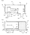
- FIG. 5 is a cross-sectional view showing a state in which the plug 10 has been inserted into the receptacle 20.
- a shield cover 21 formed by bending a metallic plate constitutes the exterior of the receptacle 20.
- the shield cover 21 is formed into a tubular body that is rectangular in cross-section, and accommodates a resin-formed housing H in an interior thereof.
- the housing H holds a receptacle-side terminal part 29.
- the receptacle-side terminal part 29 is held in the housing H so that one end is exposed on the interior of the receptacle 20 and another end is exposed on the exterior of the receptacle 20.
- a terminal part of the plug 10 makes contact with the end of the receptacle-side terminal part 29 exposed on the interior of the receptacle 20.
- the end of the receptacle-side terminal part 29 that is exposed on the exterior of the receptacle 20 is soldered or otherwise bonded to a circuit pattern formed on the substrate 1.
- the plug 10 has an engagement projection part 11 that protrudes vertically in relation to the direction in which the plug 10 is inserted into the receptacle 20. A detailed description of the structure of the plug 10 is not provided; however, the engagement projection part 11 is formed using a resin, metal, or another appropriate material. In the present embodiment, the plug 10 has two engagement projection parts 11.
- the shield cover 21 that constitutes the receptacle 20 has an engagement hole 28 in which the engagement projection part 11 of the plug 10 engages when the plug 10 is inserted in the receptacle 20.
- the engagement hole 28 provided to the receptacle 20 is formed through the shield cover 21 in the region of the shield cover 21 that faces the substrate 1.
- the engagement hole 28 is formed in a bottom surface 21a of the shield cover 21. Accordingly, as shown in FIG. 5 , when the plug 10 is inserted in the receptacle 20, the engagement projection part 11 of the plug 10 engages so as to pass through the engagement hole 28 of the receptacle 20, and the inserted state is maintained. In addition, a state of contact between the terminal part of the plug 10 and the receptacle-side terminal part 29 of the receptacle 20 is maintained.
- a plurality of cutout pieces 23a, 23b, 23c, 23d (four in the present embodiment) cut out and formed from the tubular body constituting the shield cover 21 are provided to the shield cover 21.
- Each of the cutout pieces 23a, 23b, 23c, 23d is inserted into and locked within a plurality of through-holes 2 provided to the substrate 1.
- the bottom surface 21a of the shield cover 21 (tubular body) constituting the receptacle 20 is mounted facing the substrate 1.
- the cutout pieces 23a, 23c are formed on the shield cover 21 nearer to the opening 22 than to the region wherein the engagement hole 28 is provided.
- the cutout pieces 23a, 23c are cut out and formed from side surfaces 21b, 21c of the tubular body constituting the shield cover 21, the side surfaces being vertically disposed with respect to the substrate 1.
- the cutout pieces 23b, 23d are cut out and formed from the bottom surface 21a of the shield cover 21.
- the cutout pieces 23b, 23d are formed in the rear-end portion of the shield cover 21, on which the housing H is positioned.
- the cutout pieces 23b, 23d are formed so that a base part 25b, 25d is wider than a tip part 24b, 24d.
- the cutout pieces 23b, 23d are formed so that the difference between the size (width) of the base part 25b, 25d and the size (width) of the tip part 24b, 24d is expressed in a step-like form.
- the housing H comes into contact with the substrate 1 when the receptacle 20 is mounted on the substrate 1; therefore, the base parts 25b, 25d do not come into contact with the substrate 1.
- the cutout pieces 23b, 23d may be formed in a tapering shape that gradually becomes smaller from the base part 25b, 25d towards the tip part 24b, 24d.
- the cutout pieces 23a, 23c which are formed in the shield cover 21 nearer to the opening 22 than to the region to which the engagement hole 28 is provided, are cut out and formed from a surface (the side surface 21b, 21c) that is different from the surface to which the engagement hole 28 is provided (bottom surface 21a). If the cutout pieces 23a, 23c are cut out and formed from the same bottom surface 21a to which the engagement hole 28 is provided, the holes created in the shield cover 21 by cutting out portions for the cutout pieces 23a, 23c will be created in the same bottom surface 21a in which the engagement hole 28 is formed. In that case, the cutout pieces 23a, 23c will be formed in the shield cover 21 nearer to the opening 22 than to the region to which the engagement hole 28 is provided.
- the fact that the portions of the cutout pieces 23a, 23c have been cut out from the shield cover 21 may lead to the engagement projection part 11 of the plug 10 getting stuck in the holes formed in the shield cover 21 before the engagement projection part 11 has reached the engagement hole 28.
- this problem does not arise in the present embodiment because the cutout pieces 23a, 23c, which are formed in the shield cover 21 nearer to the opening 22 than to the region to which the engagement hole 28 is provided, are cut out and formed from a surface (the side surface 21b, 21c) that is different from the surface to which the engagement hole 28 is provided (bottom surface 21a).
- the receptacle 20 is provided with a space-retaining part S that keeps the region of the shield cover 21 to which the engagement hole 28 is provided apart from the substrate 1 by a set spacing, in a state in which the receptacle 20 is mounted on the substrate 1.
- the space-retaining part S is composed of spacer member 26 that is provided to the bottom surface 21a of the shield cover 21 so as to be positioned between the shield cover 21 and the substrate 1.
- the spacer member 26 causes the region of the shield cover 21 to which the engagement hole 28 is provided to be positioned away from the substrate 1 by a set distance.
- a resin material or another appropriate material is used to form the spacer member 26 as an integrated unit with the housing H.
- the spacer member 26 extends from the rear-end portion of the shield cover 21 to which the housing H is provided, toward the anterior opening 22. However, as shown in FIG. 4 , the spacer member 26 is constructed so as to not overlap with the region to which the engagement hole 28 is provided.
- the spacer member 26 has an anchoring member 27 that stretches vertically from the bottom surface toward the substrate 1.
- a resin material or another appropriate material is used to form the anchoring member 27 also as an integrated unit with the housing H.
- the anchoring member 27 is inserted into a through-hole 3 formed in the substrate 1, whereby the receptacle 20 is anchored to the substrate 1. Therefore, the receptacle 20 is mounted on the substrate 1 in a state in which the bottom surface of the spacer member 26 faces the substrate 1.
- the bottom surface 21a of the shield cover 21 i.e., the region of the shield cover 21 to which the engagement hole 28 is provided, is held positioned away from the substrate 1 by a set distance.
- the receptacle in the connector according to the second embodiment has a structure that differs from the structure of the receptacle described in the first embodiment.
- a description of the connector according to the second embodiment is provided below; however, descriptions of structures that are the same as in the first embodiment have not been provided.
- FIG. 6 is a side view of the receptacle 20 of the second embodiment.
- FIG. 7 is a cross-sectional view of a state in which the plug 10 has been inserted into the receptacle 20.
- the receptacle 20 of the connector of the present embodiment does not have the spacer member 26 described in the first embodiment. Specifically, the spacer member 26 that can be used as the abovementioned space-retaining part S is not present between the shield cover 21 and the substrate 1.
- the present embodiment is configured so that the base parts 25a, 25c of the cutout pieces 23a, 23c are formed wider than the tip parts 24a, 24c, whereby a part of the cutout pieces 23a, 23c will be inserted into the substrate 1 when the receptacle 20 is mounted on the substrate 1.
- the present embodiment is configured so that the cutout pieces 23a, 23c, which serve as the space-retaining part S, have the base parts 25a, 25c formed wider than the tip parts 24a, 24c; the cutout pieces 23a, 23c and the substrate 1 are caused to interfere with each other when the receptacle 20 is mounted on the substrate 1; and the cutout pieces 23a, 23c are prevented from being inserted into the through-holes 2 between the tip parts 24a, 24c and the base parts 25a, 25c.
- the region of the shield cover 21 to which the engagement hole 28 is provided is positioned away from the substrate 1 by a set distance.
- the bottom surface 21a of the shield cover 21 i.e., the region of the shield cover 21 to which the engagement hole 28 is provided, is held positioned away from the substrate 1 by a set distance.
- engagement holes are provided only to the bottom surface of the shield cover; however, engagement holes may be additionally provided to other surfaces of the shield cover.
- engagement holes may be provided to both the bottom and top surfaces of the shield cover.
- engagement projection parts may be provided to the bottom and top surfaces of the plug, so as to engage with the engagement holes provided to the bottom and top surfaces of the shield cover. Examples have been described for the abovementioned embodiments in which two engagement holes are provided to the shield cover; however, it is also possible to have a construction in which one engagement hole is provided to the shield cover, and constructions in which three or more engagement holes are provided. In such cases, an appropriate number of engagement projection parts may be provided to the plug as well, so as to engage with the engagement holes provided to the shield cover.
- the cutout pieces 23a, 23c are cut out and formed from another surface besides the surface to which the engagement hole 28 is provided, the cutout pieces 23a, 23c being nearer to the opening than to the engagement hole 28.
- the cutout pieces 23a, 23c may be cut out and formed from the same surface as the surface to which the engagement hole 28 is provided.
- the housing H comes into contact with the substrate 1 at the rear-end portion of the receptacle 20 (the portion to which the cutout pieces 23b, 23d are provided).
- the housing H is made thin, whereby the housing H and the substrate 1 do not come into contact.
- the base parts 25b, 25d of the cutout pieces 23b, 23d are formed wider than the tip parts 24b, 24d, and therefore a part of the cutout pieces 23b, 23d will be inserted into the substrate 1 when the receptacle 20 is mounted on the substrate 1.
- the cutout pieces 23b, 23d function as the abovementioned space-retaining part S.
- the base parts 25b, 25d are formed wider than the tip parts 24b, 24d; the cutout pieces 23b, 23d and the substrate 1 are caused to interfere with each other when the receptacle 20 is mounted on the substrate 1; and the cutout pieces 23b, 23d are prevented from being inserted into the through-holes 2 between the tip parts 24b, 24d and the base parts 25b, 25d.
- the entire bottom surface 21a of the shield cover 21 is positioned to be separated from the substrate 1 by a set distance.
Landscapes
- Details Of Connecting Devices For Male And Female Coupling (AREA)
- Coupling Device And Connection With Printed Circuit (AREA)
- Connector Housings Or Holding Contact Members (AREA)
Abstract
A connector comprises a plug (10), and a receptacle (20). The receptacle (20) has a housing (H) for holding a receptacle-side terminal part (29) in an interior of a tubular shield cover (21) that forms the opening (22). An engagement projection part (11) provided to the plug (10) engages with an engagement hole (28) provided to the receptacle (20) when the plug (10) is inserted into the receptacle (20), and the inserted state is maintained. The engagement hole (28) is provided to a region of the shield cover (21) that faces the substrate (1); and in a state in which the receptacle (20) is mounted on the substrate (1), the region of the shield cover (21) to which the engagement hole (28) is provided is positioned away from the substrate (1) by a set distance.
Description
- The present invention relates to a connector comprising a plug and a receptacle mounted on a substrate and having an opening into which the plug is inserted, and relates more particularly to a connector constructed so that the receptacle has a housing for holding a receptacle-side terminal part in the interior of a tubular shield cover that forms an opening, and when the plug is inserted into the receptacle an engagement projection part provided to the plug engages with an engagement hole provided to the receptacle.
- Connectors comprising a plug and a receptacle are used for connecting a variety of devices to wiring patterns on circuit boards in the interior of a variety of electrical devices. For example, a plug is provided to a distal end of wiring linked to a device, a receptacle is provided on the wiring pattern of a circuit board, and the plug is inserted into the receptacle, whereby the device and the wiring pattern are connected. In the connector described in Japanese Patent No.
3966414 - Typically, a plurality of wires are arranged in a predetermined sequence within the plug, so that the wires can be bundled together and connected as a single entity to the receptacle. Similarly, a receptacle-side terminal part provided to the receptacle also has a plurality of terminals arranged in the same sequence, so as to properly connect with the arranged wires. The plurality of terminals in the receptacle-side terminal part of the receptacle may also be arranged in the opposite sequence from the sequence mentioned above, in which case the plug may be reversed and inserted into the receptacle (i.e., the plug may be reverse-mounted).
- In the connector described in Japanese Patent No.
3966414 - With the foregoing aspects of the prior art in view, it is an object of the present invention to provide a connector in which the engagement projection part of a plug can reliably engage with the engagement hole of a receptacle when the plug is reverse-mounted.
- The connector according to the present invention and used to achieve the aforesaid object is characterized in comprising a plug, and a receptacle mounted on a substrate, and having an opening into which the plug is inserted; the receptacle having a housing for holding a receptacle-side terminal part in an interior of a tubular shield cover that forms the opening of the receptacle; wherein an engagement projection part provided to the plug engages with an engagement hole provided to a region of the shield cover of the receptacle that faces the substrate when the plug is inserted into the receptacle, and in a state in which the receptacle is mounted on the substrate, the region of the shield cover to which the engagement hole is provided is positioned away from the substrate by a set distance.
- According to the above aspect, even in a state where the plug has been inserted into the receptacle in a reverse-mounted form and the engagement projection part of the plug has engaged with the engagement hole of the shield cover, a space sufficient to prevent the engagement projection part from interfering with the substrate will be ensured between the region to which the engagement hole is provided and the substrate.
Accordingly, it is possible to provide a connector in which the engagement projection part of a plug can reliably engage with the engagement hole of a receptacle when the plug is reverse-mounted. - According to another aspect of the connector according to the present invention, the shield cover is a tubular body that is rectangular in cross-section, and each of a plurality of cutout pieces cut out and formed from the tubular body is inserted and locked into a plurality of through-holes provided to the substrate, whereby a bottom surface of the shield cover is mounted facing the substrate.
- According to the above aspect, the cutout pieces are caused to lock into the substrate, whereby the receptacle can be reliably mounted on the substrate.
- According to another aspect of the connector according to the present invention, base parts of the cutout pieces are formed wider than tip parts, whereby a part of the cutout pieces is inserted into the substrate when the receptacle is mounted on the substrate.
- According to the above aspect, the cutout pieces are not entirely inserted into the substrate, but have a portion which is not inserted into the substrate. Therefore, the shield cover will assume a state of being suspended above the substrate by an amount corresponding to the uninserted portion. As a result, even in a state where the plug has been inserted into the receptacle in a reverse-mounted form and the engagement projection part of the plug has engaged with the engagement hole of the shield cover, a space sufficient to prevent the engagement projection part from interfering with the substrate will be ensured between the region to which the engagement hole is provided and the substrate.
- According to another aspect of the connector according to the present invention, cutout pieces included among the plurality of cutout pieces and formed nearer to the opening than to the region of the shield cover to which the engagement hole is provided, are cut out and formed from a surface different from the surface to which the engagement hole is provided.
- If the cutout pieces are cut out and formed from the same bottom surface to which the engagement hole is provided, the holes created in the shield cover by cutting out from the shield cover portions for the cutout pieces will be created in the same bottom surface in which the engagement hole is formed. In that case, the cutout pieces will be formed in the shield cover nearer to the opening than to the region to which the engagement hole is provided. As the plug is inserted into the receptacle, the fact that the cutout piece portions have been cut out may lead to the engagement projection part of the plug getting stuck in the holes formed in the shield cover before the engagement projection part has reached the engagement hole.
However, according to the above aspect, this problem does not arise because the cutout pieces which are formed in the shield cover nearer to the opening than to the region to which the engagement hole is provided, are cut out and formed from a surface that is different from the surface to which the engagement hole is provided. Accordingly, the engagement projection part of the plug can be caused to reliably engage with the engagement hole of the shield cover. - According to another aspect of the connector according to the present invention, a spacer member is provided between the shield cover and the substrate.
- According to the above aspect, the shield cover will assume a state of being suspended above the substrate by an amount corresponding to the thickness of the spacer member. As a result, even in a state where the plug has been inserted into the receptacle in a reverse-mounted form and the engagement projection part of the plug has engaged with the engagement hole of the shield cover, a space sufficient to prevent the engagement projection part from interfering with the substrate will be ensured between the region to which the engagement hole is provided and the substrate.
-
-
FIG. 1 is a perspective view of a receptacle; -
FIG. 2 is a front view of the receptacle; -
FIG. 3 is a side view of the receptacle; -
FIG. 4 is a bottom view of the receptacle; -
FIG. 5 is a cross-sectional view showing a state in which a plug has been inserted into the receptacle; -
FIG. 6 is a side view of the receptacle; and -
FIG. 7 is a cross-sectional view showing a state in which a plug has been inserted into the receptacle. - The following is a description of a connector according to the first embodiment, with reference to the accompanying drawings. The connector according to the present embodiment comprises a
plug 10, and areceptacle 20 mounted on asubstrate 1 and having anopening 22 into which theplug 10 is inserted.FIG. 1 is a perspective view of thereceptacle 20 provided to the connector of the first embodiment.FIG. 2 is a front view of thereceptacle 20,FIG. 3 is side view of thereceptacle 20, andFIG. 4 is a bottom view of thereceptacle 20.FIG. 5 is a cross-sectional view showing a state in which theplug 10 has been inserted into thereceptacle 20. - As shown in
FIGS. 1 to 5 , ashield cover 21 formed by bending a metallic plate constitutes the exterior of thereceptacle 20. Theshield cover 21 is formed into a tubular body that is rectangular in cross-section, and accommodates a resin-formed housing H in an interior thereof. The housing H holds a receptacle-side terminal part 29. The receptacle-side terminal part 29 is held in the housing H so that one end is exposed on the interior of thereceptacle 20 and another end is exposed on the exterior of thereceptacle 20. When theplug 10 is inserted via theopening 22 of theshield cover 21 and pushed inside, a terminal part of the plug 10 (not shown) makes contact with the end of the receptacle-side terminal part 29 exposed on the interior of thereceptacle 20. The end of the receptacle-side terminal part 29 that is exposed on the exterior of thereceptacle 20 is soldered or otherwise bonded to a circuit pattern formed on thesubstrate 1. - The
plug 10 has anengagement projection part 11 that protrudes vertically in relation to the direction in which theplug 10 is inserted into thereceptacle 20. A detailed description of the structure of theplug 10 is not provided; however, theengagement projection part 11 is formed using a resin, metal, or another appropriate material. In the present embodiment, theplug 10 has twoengagement projection parts 11. Theshield cover 21 that constitutes thereceptacle 20 has anengagement hole 28 in which theengagement projection part 11 of theplug 10 engages when theplug 10 is inserted in thereceptacle 20.
Theengagement hole 28 provided to thereceptacle 20 is formed through theshield cover 21 in the region of theshield cover 21 that faces thesubstrate 1. Specifically, in the present embodiment, theengagement hole 28 is formed in abottom surface 21a of theshield cover 21.
Accordingly, as shown inFIG. 5 , when theplug 10 is inserted in thereceptacle 20, theengagement projection part 11 of theplug 10 engages so as to pass through theengagement hole 28 of thereceptacle 20, and the inserted state is maintained. In addition, a state of contact between the terminal part of theplug 10 and the receptacle-side terminal part 29 of thereceptacle 20 is maintained. - A plurality of
cutout pieces shield cover 21 are provided to theshield cover 21. Each of thecutout pieces holes 2 provided to thesubstrate 1. As a result, thebottom surface 21a of the shield cover 21 (tubular body) constituting thereceptacle 20 is mounted facing thesubstrate 1. - In the present embodiment, the
cutout pieces shield cover 21 nearer to theopening 22 than to the region wherein theengagement hole 28 is provided. Thecutout pieces side surfaces shield cover 21, the side surfaces being vertically disposed with respect to thesubstrate 1. Thecutout pieces bottom surface 21a of theshield cover 21.
Thecutout pieces shield cover 21, on which the housing H is positioned. Thecutout pieces base part tip part cutout pieces base part tip part substrate 1 when thereceptacle 20 is mounted on thesubstrate 1; therefore, thebase parts substrate 1. Thecutout pieces base part tip part - As described above, the
cutout pieces shield cover 21 nearer to theopening 22 than to the region to which theengagement hole 28 is provided, are cut out and formed from a surface (theside surface engagement hole 28 is provided (bottom surface 21a).
If thecutout pieces same bottom surface 21a to which theengagement hole 28 is provided, the holes created in theshield cover 21 by cutting out portions for thecutout pieces same bottom surface 21a in which theengagement hole 28 is formed. In that case, thecutout pieces shield cover 21 nearer to theopening 22 than to the region to which theengagement hole 28 is provided. As theplug 10 is inserted into thereceptacle 20, the fact that the portions of thecutout pieces shield cover 21 may lead to theengagement projection part 11 of theplug 10 getting stuck in the holes formed in theshield cover 21 before theengagement projection part 11 has reached theengagement hole 28.
However, this problem does not arise in the present embodiment because thecutout pieces shield cover 21 nearer to theopening 22 than to the region to which theengagement hole 28 is provided, are cut out and formed from a surface (theside surface engagement hole 28 is provided (bottom surface 21a). - The
receptacle 20 is provided with a space-retaining part S that keeps the region of theshield cover 21 to which theengagement hole 28 is provided apart from thesubstrate 1 by a set spacing, in a state in which thereceptacle 20 is mounted on thesubstrate 1. In the present embodiment, the space-retaining part S is composed ofspacer member 26 that is provided to thebottom surface 21a of theshield cover 21 so as to be positioned between theshield cover 21 and thesubstrate 1. Thespacer member 26 causes the region of theshield cover 21 to which theengagement hole 28 is provided to be positioned away from thesubstrate 1 by a set distance. In the present embodiment, a resin material or another appropriate material is used to form thespacer member 26 as an integrated unit with the housing H. Thespacer member 26 extends from the rear-end portion of theshield cover 21 to which the housing H is provided, toward theanterior opening 22. However, as shown inFIG. 4 , thespacer member 26 is constructed so as to not overlap with the region to which theengagement hole 28 is provided. - The
spacer member 26 has an anchoringmember 27 that stretches vertically from the bottom surface toward thesubstrate 1. A resin material or another appropriate material is used to form the anchoringmember 27 also as an integrated unit with the housing H. The anchoringmember 27 is inserted into a through-hole 3 formed in thesubstrate 1, whereby thereceptacle 20 is anchored to thesubstrate 1. Therefore, thereceptacle 20 is mounted on thesubstrate 1 in a state in which the bottom surface of thespacer member 26 faces thesubstrate 1. - Accordingly, as shown in
FIG. 5 , thebottom surface 21a of theshield cover 21; i.e., the region of theshield cover 21 to which theengagement hole 28 is provided, is held positioned away from thesubstrate 1 by a set distance. As a result, even if theplug 10 is inserted into thereceptacle 20 in a reverse-mounted state, and theengagement projection part 11 of theplug 10 is in a state of engagement with theengagement hole 28 of theshield cover 21, spacing sufficient to prevent theengagement projection part 11 from interfering with thesubstrate 1 is ensured between the region to which theengagement hole 28 is provided and thesubstrate 1. Therefore, theplug 10 and thereceptacle 20 will be held in a reliable state of engagement. - The receptacle in the connector according to the second embodiment has a structure that differs from the structure of the receptacle described in the first embodiment. A description of the connector according to the second embodiment is provided below; however, descriptions of structures that are the same as in the first embodiment have not been provided.
-
FIG. 6 is a side view of thereceptacle 20 of the second embodiment.FIG. 7 is a cross-sectional view of a state in which theplug 10 has been inserted into thereceptacle 20. As illustrated in the drawings, thereceptacle 20 of the connector of the present embodiment does not have thespacer member 26 described in the first embodiment. Specifically, thespacer member 26 that can be used as the abovementioned space-retaining part S is not present between theshield cover 21 and thesubstrate 1. - The present embodiment is configured so that the
base parts cutout pieces tip parts cutout pieces substrate 1 when thereceptacle 20 is mounted on thesubstrate 1. Specifically, the present embodiment is configured so that thecutout pieces base parts tip parts cutout pieces substrate 1 are caused to interfere with each other when thereceptacle 20 is mounted on thesubstrate 1; and thecutout pieces holes 2 between thetip parts base parts FIG. 7 , the region of theshield cover 21 to which theengagement hole 28 is provided is positioned away from thesubstrate 1 by a set distance. - Accordingly, as shown in
FIG. 7 , thebottom surface 21a of theshield cover 21; i.e., the region of theshield cover 21 to which theengagement hole 28 is provided, is held positioned away from thesubstrate 1 by a set distance. As a result, even if theplug 10 is inserted into thereceptacle 20 in a reverse-mounted state, and theengagement projection part 11 of theplug 10 is in a state of engagement with theengagement hole 28 of theshield cover 21, spacing sufficient to prevent theengagement projection part 11 from interfering with thesubstrate 1 is ensured between the region to which theengagement hole 28 is provided and thesubstrate 1. Therefore, theplug 10 and thereceptacle 20 will be held in a reliable state of engagement. - Examples have been described for the abovementioned embodiments in which engagement holes are provided only to the bottom surface of the shield cover; however, engagement holes may be additionally provided to other surfaces of the shield cover. For example, engagement holes may be provided to both the bottom and top surfaces of the shield cover. Moreover, engagement projection parts may be provided to the bottom and top surfaces of the plug, so as to engage with the engagement holes provided to the bottom and top surfaces of the shield cover.
Examples have been described for the abovementioned embodiments in which two engagement holes are provided to the shield cover; however, it is also possible to have a construction in which one engagement hole is provided to the shield cover, and constructions in which three or more engagement holes are provided. In such cases, an appropriate number of engagement projection parts may be provided to the plug as well, so as to engage with the engagement holes provided to the shield cover. - Examples have been described for the first embodiment and second embodiment in which the
cutout pieces engagement hole 28 is provided, thecutout pieces engagement hole 28. Alternatively, thecutout pieces engagement hole 28 is provided. In this case, it is possible to make an adjustment to the shape of theengagement projection part 11 of theplug 10, as well as the position, shape, and other parameters relating to the cutting performed to form thecutout pieces cutout pieces engagement projection part 11 of theplug 10 will either not get stuck in the holes that are formed in theshield cover 21, or, if theengagement projection part 11 does get stuck, can be removed therefrom. - Examples have been describe above, in which the housing H comes into contact with the
substrate 1 at the rear-end portion of the receptacle 20 (the portion to which thecutout pieces substrate 1 do not come into contact. In this case, thebase parts cutout pieces tip parts cutout pieces substrate 1 when thereceptacle 20 is mounted on thesubstrate 1. Specifically, thecutout pieces base parts tip parts cutout pieces substrate 1 are caused to interfere with each other when thereceptacle 20 is mounted on thesubstrate 1; and thecutout pieces holes 2 between thetip parts base parts bottom surface 21a of theshield cover 21 is positioned to be separated from thesubstrate 1 by a set distance.
Claims (5)
- A connector comprising a plug (10), and a receptacle (20) mounted on a substrate (1) and having an opening (22) into which the plug (10) is inserted, the receptacle (20) having a housing (H) for holding a receptacle-side terminal part (29) in an interior of a tubular shield cover (21) that forms the opening (22), and an engagement projection part (11) provided to the plug (10) engaging with an engagement hole (28) provided to the receptacle (20) when the plug (10) is inserted into the receptacle (20); wherein
the engagement hole (28) is provided to a region of the shield cover (21) that faces the substrate (1); and
in a state in which the receptacle (20) is mounted on the substrate (1), the region of the shield cover (21) to which the engagement hole (28) is provided is positioned away from the substrate (1) by a set distance. - The connector of Claim 1, wherein
the shield cover (21) is a tubular body that is rectangular in cross-section, and each of a plurality of cutout pieces (23a, 23b, 23c, 23d) cut out and formed from the tubular body is inserted and locked into a plurality of through-holes (2) provided to the substrate (1), whereby a bottom surface (21a) of the shield cover (21) is mounted facing the substrate (1). - The connector of Claim 2, wherein
base parts (25b, 25d) of the cutout pieces (23b, 23d) are formed wider than tip parts (24b, 24d), whereby a part of the cutout pieces (23b, 23d) will be inserted into the substrate (1) when the receptacle (20) is mounted on the substrate (1). - The connector of Claim 2 or 3, wherein
cutout pieces (23a, 23c) included among the plurality of cutout pieces (23a, 23b, 23c, 23d) and formed nearer to the opening (22) than to the region of the shield cover (21) to which the engagement hole (28) is provided are cut out and formed from a surface different from the surface to which the engagement hole (28) is provided. - The connector of Claim 1 or 2, wherein a spacer member (26) is provided between the shield cover (21) and the substrate (1).
Applications Claiming Priority (1)
| Application Number | Priority Date | Filing Date | Title |
|---|---|---|---|
| JP2007278999A JP2009110697A (en) | 2007-10-26 | 2007-10-26 | Connector |
Publications (1)
| Publication Number | Publication Date |
|---|---|
| EP2053703A2 true EP2053703A2 (en) | 2009-04-29 |
Family
ID=40282429
Family Applications (1)
| Application Number | Title | Priority Date | Filing Date |
|---|---|---|---|
| EP08018646A Withdrawn EP2053703A2 (en) | 2007-10-26 | 2008-10-24 | Connector |
Country Status (6)
| Country | Link |
|---|---|
| US (1) | US20090149078A1 (en) |
| EP (1) | EP2053703A2 (en) |
| JP (1) | JP2009110697A (en) |
| KR (1) | KR20090042728A (en) |
| CN (1) | CN101420087A (en) |
| TW (1) | TW200919855A (en) |
Cited By (1)
| Publication number | Priority date | Publication date | Assignee | Title |
|---|---|---|---|---|
| EP2571111A3 (en) * | 2011-09-13 | 2014-12-03 | Hosiden Corporation | Connector |
Families Citing this family (5)
| Publication number | Priority date | Publication date | Assignee | Title |
|---|---|---|---|---|
| TWM353554U (en) * | 2008-06-16 | 2009-03-21 | Htc Corp | Electronic device and receptacle connector thereof |
| US7806732B1 (en) * | 2009-05-11 | 2010-10-05 | Hsu-Li Yen | Connector assembly |
| CN104967904B (en) | 2014-04-10 | 2018-08-17 | 腾讯科技(深圳)有限公司 | The method and device of terminal video recording and playback |
| JP7401224B2 (en) * | 2019-08-29 | 2023-12-19 | 矢崎総業株式会社 | Board-mounted connectors and boards with connectors |
| KR20220015086A (en) | 2020-07-30 | 2022-02-08 | 김대곤 | easy-to-walk pleats pants |
Citations (1)
| Publication number | Priority date | Publication date | Assignee | Title |
|---|---|---|---|---|
| JP3966414B2 (en) | 2003-07-08 | 2007-08-29 | Smk株式会社 | connector |
Family Cites Families (9)
| Publication number | Priority date | Publication date | Assignee | Title |
|---|---|---|---|---|
| DE19736607C1 (en) * | 1997-08-22 | 1999-07-15 | Dunkel Otto Gmbh | PCB socket |
| JP2000223191A (en) * | 1999-01-27 | 2000-08-11 | Mitsumi Electric Co Ltd | Small connector |
| US6475033B1 (en) * | 2001-10-10 | 2002-11-05 | Hon Hai Precision Ind. Co., Ltd. | Electrical connector |
| US6619986B1 (en) * | 2002-04-19 | 2003-09-16 | Hon Hai Precision Ind. Co., Ltd. | Electrical connector with metal shield |
| JP4030954B2 (en) * | 2003-11-28 | 2008-01-09 | ヒロセ電機株式会社 | Receptacle electrical connector |
| US6986681B2 (en) * | 2004-02-20 | 2006-01-17 | Advanced Connectek, Inc. | HDMI connector |
| US7097507B1 (en) * | 2005-06-02 | 2006-08-29 | Hon Hai Precision Ind. Co., Ltd. | Electrical connector with improved shell |
| JP2007005234A (en) * | 2005-06-27 | 2007-01-11 | Hirose Electric Co Ltd | Electrical connector with shield case |
| TWM291116U (en) * | 2005-11-24 | 2006-05-21 | Joinsoon Electronic Mfg Co Ltd | EMI-elimination structure for connector set |
-
2007
- 2007-10-26 JP JP2007278999A patent/JP2009110697A/en not_active Abandoned
-
2008
- 2008-06-09 TW TW097121416A patent/TW200919855A/en unknown
- 2008-09-26 CN CNA2008101687260A patent/CN101420087A/en active Pending
- 2008-10-21 US US12/255,195 patent/US20090149078A1/en not_active Abandoned
- 2008-10-23 KR KR1020080104197A patent/KR20090042728A/en not_active Withdrawn
- 2008-10-24 EP EP08018646A patent/EP2053703A2/en not_active Withdrawn
Patent Citations (1)
| Publication number | Priority date | Publication date | Assignee | Title |
|---|---|---|---|---|
| JP3966414B2 (en) | 2003-07-08 | 2007-08-29 | Smk株式会社 | connector |
Cited By (2)
| Publication number | Priority date | Publication date | Assignee | Title |
|---|---|---|---|---|
| EP2571111A3 (en) * | 2011-09-13 | 2014-12-03 | Hosiden Corporation | Connector |
| EP3157106A1 (en) * | 2011-09-13 | 2017-04-19 | Hosiden Corporation | Connector |
Also Published As
| Publication number | Publication date |
|---|---|
| KR20090042728A (en) | 2009-04-30 |
| TW200919855A (en) | 2009-05-01 |
| JP2009110697A (en) | 2009-05-21 |
| US20090149078A1 (en) | 2009-06-11 |
| CN101420087A (en) | 2009-04-29 |
Similar Documents
| Publication | Publication Date | Title |
|---|---|---|
| US8678844B2 (en) | Electrical connector with one action automatic mechanism | |
| US7597594B2 (en) | Electrical connecting terminal | |
| KR101012619B1 (en) | Electrical Connectors for Flat Conductors | |
| US7806702B2 (en) | Connector for an electric device such as a board | |
| JP2007073199A (en) | Connector, connector receptacle, and connector plug | |
| JP2004235142A (en) | Latch for card edge connector | |
| US20090149078A1 (en) | Connector | |
| JP2009104851A (en) | Connector | |
| CN100411254C (en) | surface mount connector | |
| US6406305B1 (en) | Electrical connector having compression terminal module therein | |
| JP6267857B2 (en) | Flat cable connector | |
| KR101042120B1 (en) | Electrical connector | |
| JP2003045525A (en) | connector | |
| JP4774956B2 (en) | Connector and connector receptacle | |
| JP2010176958A (en) | Electric connector | |
| JP2007287519A (en) | Connection device | |
| JP7393132B2 (en) | Board connector and board connector structure | |
| JP5842677B2 (en) | Connector device | |
| US20250293455A1 (en) | Connector and connector pair | |
| JP3117155U (en) | Electrical connector | |
| JP4099164B2 (en) | connector | |
| JP2009252696A (en) | Board connector | |
| JP4421976B2 (en) | connector | |
| JP2006147938A (en) | Electronic component mounting method, electronic component, and module with electronic component mounted therein | |
| JP2005116285A (en) | Connector for substrate |
Legal Events
| Date | Code | Title | Description |
|---|---|---|---|
| PUAI | Public reference made under article 153(3) epc to a published international application that has entered the european phase |
Free format text: ORIGINAL CODE: 0009012 |
|
| AK | Designated contracting states |
Kind code of ref document: A2 Designated state(s): AT BE BG CH CY CZ DE DK EE ES FI FR GB GR HR HU IE IS IT LI LT LU LV MC MT NL NO PL PT RO SE SI SK TR |
|
| AX | Request for extension of the european patent |
Extension state: AL BA MK RS |
|
| STAA | Information on the status of an ep patent application or granted ep patent |
Free format text: STATUS: THE APPLICATION IS DEEMED TO BE WITHDRAWN |
|
| 18D | Application deemed to be withdrawn |
Effective date: 20110503 |