EP2053387A1 - Test device for platelet aggregation detection - Google Patents
Test device for platelet aggregation detection Download PDFInfo
- Publication number
- EP2053387A1 EP2053387A1 EP07291282A EP07291282A EP2053387A1 EP 2053387 A1 EP2053387 A1 EP 2053387A1 EP 07291282 A EP07291282 A EP 07291282A EP 07291282 A EP07291282 A EP 07291282A EP 2053387 A1 EP2053387 A1 EP 2053387A1
- Authority
- EP
- European Patent Office
- Prior art keywords
- capillary tube
- test device
- blood sample
- electrodes
- anyone
- Prior art date
- Legal status (The legal status is an assumption and is not a legal conclusion. Google has not performed a legal analysis and makes no representation as to the accuracy of the status listed.)
- Withdrawn
Links
- 208000010110 spontaneous platelet aggregation Diseases 0.000 title claims abstract description 8
- 238000001514 detection method Methods 0.000 title claims abstract description 6
- 239000008280 blood Substances 0.000 claims abstract description 64
- 210000004369 blood Anatomy 0.000 claims abstract description 64
- 238000000034 method Methods 0.000 claims abstract description 9
- 230000008569 process Effects 0.000 claims abstract description 9
- 230000008859 change Effects 0.000 claims abstract description 8
- 238000005086 pumping Methods 0.000 claims abstract description 3
- 102000008186 Collagen Human genes 0.000 claims description 11
- 108010035532 Collagen Proteins 0.000 claims description 11
- 229920001436 collagen Polymers 0.000 claims description 11
- 239000003795 chemical substances by application Substances 0.000 claims description 9
- BSYNRYMUTXBXSQ-UHFFFAOYSA-N Aspirin Chemical compound CC(=O)OC1=CC=CC=C1C(O)=O BSYNRYMUTXBXSQ-UHFFFAOYSA-N 0.000 claims description 6
- 229960001138 acetylsalicylic acid Drugs 0.000 claims description 6
- 238000005259 measurement Methods 0.000 claims description 5
- 230000002776 aggregation Effects 0.000 claims description 3
- 238000004220 aggregation Methods 0.000 claims description 3
- 238000004891 communication Methods 0.000 claims description 3
- 238000002347 injection Methods 0.000 claims description 3
- 239000007924 injection Substances 0.000 claims description 3
- 238000011534 incubation Methods 0.000 claims description 2
- 230000004931 aggregating effect Effects 0.000 description 5
- 230000000694 effects Effects 0.000 description 3
- XLYOFNOQVPJJNP-UHFFFAOYSA-N water Substances O XLYOFNOQVPJJNP-UHFFFAOYSA-N 0.000 description 3
- 239000012153 distilled water Substances 0.000 description 2
- 239000007788 liquid Substances 0.000 description 2
- 239000002184 metal Substances 0.000 description 2
- 230000004044 response Effects 0.000 description 2
- 239000000243 solution Substances 0.000 description 2
- LXKCHCXZBPLTAE-UHFFFAOYSA-N 3,4-dimethyl-1H-pyrazole phosphate Chemical compound OP(O)(O)=O.CC1=CNN=C1C LXKCHCXZBPLTAE-UHFFFAOYSA-N 0.000 description 1
- 230000005540 biological transmission Effects 0.000 description 1
- 230000017531 blood circulation Effects 0.000 description 1
- 238000009530 blood pressure measurement Methods 0.000 description 1
- 230000004087 circulation Effects 0.000 description 1
- 238000004737 colorimetric analysis Methods 0.000 description 1
- 238000007872 degassing Methods 0.000 description 1
- 238000010790 dilution Methods 0.000 description 1
- 239000012895 dilution Substances 0.000 description 1
- 239000011521 glass Substances 0.000 description 1
- 238000011065 in-situ storage Methods 0.000 description 1
- 238000002955 isolation Methods 0.000 description 1
- 239000012528 membrane Substances 0.000 description 1
- 230000007935 neutral effect Effects 0.000 description 1
- 230000003287 optical effect Effects 0.000 description 1
- 238000002360 preparation method Methods 0.000 description 1
- 210000002966 serum Anatomy 0.000 description 1
- 238000010008 shearing Methods 0.000 description 1
- 230000001052 transient effect Effects 0.000 description 1
- 230000007704 transition Effects 0.000 description 1
- 238000004879 turbidimetry Methods 0.000 description 1
Images


Classifications
-
- G—PHYSICS
- G01—MEASURING; TESTING
- G01N—INVESTIGATING OR ANALYSING MATERIALS BY DETERMINING THEIR CHEMICAL OR PHYSICAL PROPERTIES
- G01N27/00—Investigating or analysing materials by the use of electric, electrochemical, or magnetic means
- G01N27/02—Investigating or analysing materials by the use of electric, electrochemical, or magnetic means by investigating impedance
- G01N27/04—Investigating or analysing materials by the use of electric, electrochemical, or magnetic means by investigating impedance by investigating resistance
- G01N27/06—Investigating or analysing materials by the use of electric, electrochemical, or magnetic means by investigating impedance by investigating resistance of a liquid
- G01N27/07—Construction of measuring vessels; Electrodes therefor
-
- G—PHYSICS
- G01—MEASURING; TESTING
- G01N—INVESTIGATING OR ANALYSING MATERIALS BY DETERMINING THEIR CHEMICAL OR PHYSICAL PROPERTIES
- G01N33/00—Investigating or analysing materials by specific methods not covered by groups G01N1/00 - G01N31/00
- G01N33/48—Biological material, e.g. blood, urine; Haemocytometers
- G01N33/483—Physical analysis of biological material
- G01N33/487—Physical analysis of biological material of liquid biological material
- G01N33/49—Blood
- G01N33/4905—Determining clotting time of blood
-
- Y—GENERAL TAGGING OF NEW TECHNOLOGICAL DEVELOPMENTS; GENERAL TAGGING OF CROSS-SECTIONAL TECHNOLOGIES SPANNING OVER SEVERAL SECTIONS OF THE IPC; TECHNICAL SUBJECTS COVERED BY FORMER USPC CROSS-REFERENCE ART COLLECTIONS [XRACs] AND DIGESTS
- Y10—TECHNICAL SUBJECTS COVERED BY FORMER USPC
- Y10T—TECHNICAL SUBJECTS COVERED BY FORMER US CLASSIFICATION
- Y10T436/00—Chemistry: analytical and immunological testing
- Y10T436/11—Automated chemical analysis
-
- Y—GENERAL TAGGING OF NEW TECHNOLOGICAL DEVELOPMENTS; GENERAL TAGGING OF CROSS-SECTIONAL TECHNOLOGIES SPANNING OVER SEVERAL SECTIONS OF THE IPC; TECHNICAL SUBJECTS COVERED BY FORMER USPC CROSS-REFERENCE ART COLLECTIONS [XRACs] AND DIGESTS
- Y10—TECHNICAL SUBJECTS COVERED BY FORMER USPC
- Y10T—TECHNICAL SUBJECTS COVERED BY FORMER US CLASSIFICATION
- Y10T436/00—Chemistry: analytical and immunological testing
- Y10T436/25—Chemistry: analytical and immunological testing including sample preparation
- Y10T436/25375—Liberation or purification of sample or separation of material from a sample [e.g., filtering, centrifuging, etc.]
Definitions
- the present invention relates to a test device for platelet aggregation detection.
- test devices for exist in the market to perform such detection.
- the tests are generally performed in specialized laboratories and require a long time to obtain the results.
- Another problem of most known devices is that they require a large amount of blood, for examples those using turbidimetry e.g. a device sold by COULTER (CHRONOLOG) or test devices such as BIOLA or ENTEC MEDICAL, or those using impedance such as another device sold by COULTER or the MULTIPLATE device sold by Instrumentation Laboratory. It is often necessity to dilute the blood samples with an appropriate amount of serum.
- COULTER CHRONOLOG
- test devices such as BIOLA or ENTEC MEDICAL
- impedance such as another device sold by COULTER or the MULTIPLATE device sold by Instrumentation Laboratory. It is often necessity to dilute the blood samples with an appropriate amount of serum.
- test device that is capable of performing routine and ambulatory test i.e. using full (or whole) blood, and preferably without being obliged to dilute the blood sample, and that is capable of giving quick results to respond to ambulatory conditions or to an emergency condition of a patient.
- a step toward this aim is performed by the PFA 100 of Dade Behring which measures with full blood the occlusion time of a blood flow through an aperture in the center of a which is membrane coated with aggregating molecules such a collagen, and by the more recent device Verify Now sold by ACCUMETRICS.
- these two devices still require a large amount of blood.
- DiaMed has introduced a test by colorimetry in its IMPACT device which can be performed on a small sample of blood (130 ⁇ l).
- the present invention relates to a test device that is capable of performing an ambulatory test on a small sample of blood, and more particularly of full blood, and of giving a result in a relatively small amount of time, so that it is suitable for ambulatory or emergency conditions.
- the invention relates to a test device for platelet aggregation detection comprising :
- the invention also relates to a system comprised of a said test device and of a measurement unit having at least one impedance measuring device, such as a multimeter, coupled to the connecting device.
- the system may also comprise a pump coupled to the second end of the capillary tube and/or injection means for adding at least one agent to the blood sample.
- the invention also relates to a process for using a test device as defined above, characterized in that it comprises:
- C max being the maximum value of the capacitance obtained when blood is circulating between the electrodes.
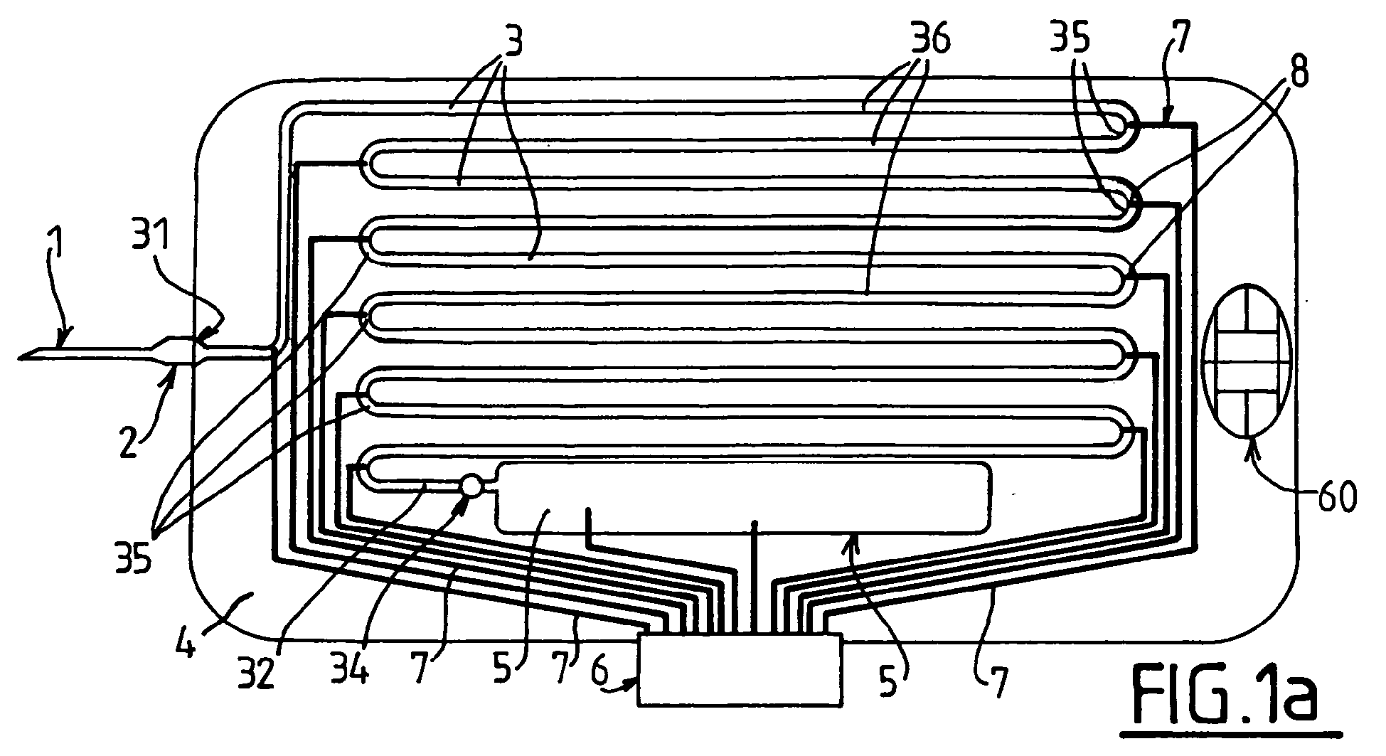
- the test device illustrated in Fig. 1 a to 1 d is comprised of a hypodermic needle 1 connected by a resilient coupler 2 to an end 31 of a capillary tube 3 which extends along a sinuous path on a glass or plastic support 4 that may be of the size of a credit card.
- the hypodermic needle and the resilient coupler can be replaced by a blood well where one or more drops of blood may be deposited.
- the capillary extends along a sinuous or concentric path or any other geometry and has a length allowing shearing the blood sample at a chosen shear rate and time.
- a vane 34 is disposed, to allow a connection of the end 32 to a closed reservoir 5 at a pressure lower than atmospheric pressure to create a pressure difference ⁇ P between both ends 31 and 32 of the capillary tube 3 which forms a micro channel along which a collected blood sample is sucked.
- the blood sample thus circulates between ends 31 and 32 where it occupies a part of the length L of the tube 3 and is collected by the reservoir 5.
- a support 4 with an integrated reservoir 5 allows a self-contained operation for an in situ or ambulatory test.
- reservoir 5 should be at the lowest pressure that would be compatible with the avoidance of degassing of the blood sample, e.g. 30 mmHg, i.e. about 4000 Pa.
- a depression or vacuum pump is connected to end 32 of the capillary tube 3, but in this case an integrated reservoir 5 is still desirable to collect the blood, because it allows discarding directly the test device with the blood sample once used.
- a connector 6 is electrically coupled to pairs of metal strips 7 on the support 4 to connect to a measuring equipment pairs of electrodes 8 that are spread along the capillary tube 3, for example as shown in curved regions 35 separating linear portions 36 of the capillary tube 3.
- the connector 6 allows connecting the pairs of electrodes to the equipment to measure the impedance with a set of conventional multimeters, and more particularly the value of the capacitance C between the pairs of electrodes, as will be discussed in the example below.
- the equipment may comprise only two multimeters: when the measurement starts, the first and second multimeter are coupled to the first and second pairs of electrodes.
- the first multimeter is coupled to the third pair of electrodes
- the second multimeter is coupled to the fourth pair of electrodes and so on.
- the device is comprised of a sandwich of three layers.
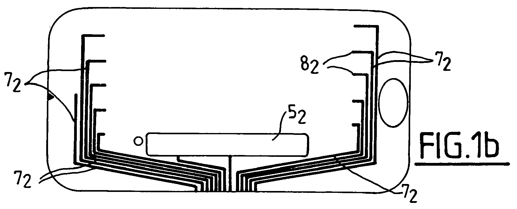
- the bottom layer ( Fig.1d ) is e.g.; made of plastic and comprises a first set of strips made of metal or of or conductive ink 7 1 having end electrodes 8 1 , an embossed region 5 1 forming the bottom of the reservoir 5, and an optional spot 34 to lodge an obturator for the channel 3.
- the middle layer ( Fig. 1 c) is e.g. made of plastic and comprises an engraved channel 3 ( e.g. by high speed water jet) and an engraved reservoir 5.
- the top layer is similar to the bottom layer (strips 7 2 , electrodes 8 2 and top region 5 2 ). It also comprises an optional opening for an electronic chip 60.
- the support 4 may be comprised of several elements namely a bottom layer 4 1 having an aperture 47 forming a reservoir, a first isolating plate 4 2 bearing connecting strips 7, then the main plate 4 0 comprising the capillary tube 3 with its pairs of measurement electrodes 8 and last a top layer 4 3 which protects the plates 4 2 and 4 0 and may comprise a second set of connecting strips.
- the capillary tube 3' is wound in a helical way, and has a circular, square or rectangular cross section for the circulation of blood.
- End 32' of the capillary tube 3' in communication with reservoir 5 ( figure 4c ) is located at the center whereas end 31' communicating with the blood well 50 is at the periphery.
- the volume of this blood well 50 is approximately 30 mm 3 to receive a blood sample.
- Injection tubes 51 and/or 52 may be provided to inject an aggregation agent.
- Figure 4a shows the plate 4 0 in perspective
- figure 4b is a top view of figure 4a
- figure 4c is a cut of figure 2c along CC.
- Figure 4d shows a partial cut along DD and detail G thereof to show a pair of electrodes 8 1 and 8 2 .
- Detail G shows two electrodes 8 1 and 8 2 of a pair of electrodes placed side by side and separated by a gap d.
- a supple capillary tube 71 having a chosen length L is disposed to follow a sinuous path and is in contact with the successive pairs of electrodes.
- Fig. 6 illustrates the change ⁇ C in the value of the capacitance with two neutral liquids, namely distilled water and a coloured solution, for three pairs of electrodes.
- Fig. 7 illustrates the change ⁇ C with a flow of distilled water followed by 50% diluted blood with an aggregating agent (collagen at 3 ⁇ g/ml), with four pairs of electrodes.
- Fig. 8 illustrates a flow of diluted blood that has been incubated during 15mn with a solution of aspirin at a concentration (5 mM) that is known to inhibit platelet aggregation to which collagen (3 ⁇ g/ml) has been added after incubation with signals from three pairs of electrodes 1,2 and 3.
- aspirin is efficient to prevent aggregation since the change of ⁇ C exhibits a sudden variation.
- Fig. 9 illustrates a flow of blood that has been incubated (curve I) during 15mm with aspirin (5mM) or not incubated (curve II). It can be seen that curve II (no aspirin added) doesn't show the sudden change of curve I, indicating that platelet aggregation may have occurred in curve II, not in curve I.
- Fig. 10 addresses the specificity of the test with a sample of blood without platelets.
- Fig. 11a and 11b test the influence of an aggregating agent (collagen) on a sample of diluted blood.
- Fig. 11a shows curves obtained with a sample without addition of collagen and Fig. 11b shows curves with a sample of the same blood with an addition of collagen (3 ⁇ g/ml).
- test device may thus be used with a sample of full (or diluted) blood with or without addition of an aggregating agent such as collagen.
- Fig. 12a to 12c show the effect of a treatment with aspirin.
- Fig. 9a shows the curve before the treatment.
- Fig. 9b and 9c show curves after 3 days of treatment (500 mg/day) respectively without addition of collagen to the sample, and with addition of collagen (3 ⁇ g/ml).
- the sharp change of ⁇ C in Fig. 9b and 9c indicates an efficiency of the treatment, independently of the presence of collagen.
- Fig. 13a and Fig. 13b show the correspondence between a test with 50% diluted blood ( Fig. 13a ) and a test with full blood ( Fig. 13b ). These curves show that the results are consistent and that the test device may be used either with full blood or with diluted blood.
- Tests on full blood are of course preferable for ambulatory or emergency tests. But tests on diluted are also of interest for various reasons, especially since the dilution allows obtaining lower shear rates with the same device.
- Another way of obtaining different values of shear rates is providing the capillary tube with two or more lengths of different cross-section. Pressure measurement at the beginning and at the end of each section allows to determine the value of the shear rate in each cross-section.
- L / D L 2 ⁇ ⁇ / S ⁇ ⁇ ⁇ P 4 ⁇ ⁇ w ⁇ ⁇
- the shear rate of the blood sample in the capillary tube is for example between 200s -1 and 1000s -1 , more particularly between 500s -1 and 700s -1 , the preferred value being 600s -1 .
- D is for example between 100 ⁇ m and 800 ⁇ m and preferably between 100 ⁇ m and 500 ⁇ m.
- the volume of the blood sample is for example between 15 ⁇ l and 1mt (e.g. 100 ⁇ l) and it is for example chosen so that the sample occupies only part of the length of the capillary tube.
- the maximal transit time in the capillary tube is about 3 minutes.
- the above formula and the following table allow to adapt the shear rate, the pressure differential ⁇ P and the transit time in a capillary tube of length L.
- test device is compatible with a certain degree of miniaturization. Samples of volume lower than 100 ⁇ l (e.g.15 ⁇ l which corresponds to a single drop of blood) can be accommodated. Also, sub-millimetre electrodes may be used. L, which is equal to 1 mm in the examples, may be reduced, e.g. to 120 ⁇ m, down to about 25 ⁇ m.
Landscapes
- Health & Medical Sciences (AREA)
- Life Sciences & Earth Sciences (AREA)
- Chemical & Material Sciences (AREA)
- Engineering & Computer Science (AREA)
- Biomedical Technology (AREA)
- Physics & Mathematics (AREA)
- Hematology (AREA)
- Analytical Chemistry (AREA)
- General Health & Medical Sciences (AREA)
- General Physics & Mathematics (AREA)
- Immunology (AREA)
- Pathology (AREA)
- Biochemistry (AREA)
- Chemical Kinetics & Catalysis (AREA)
- Ecology (AREA)
- Biophysics (AREA)
- Electrochemistry (AREA)
- Molecular Biology (AREA)
- Urology & Nephrology (AREA)
- Food Science & Technology (AREA)
- Medicinal Chemistry (AREA)
- Investigating Or Analysing Biological Materials (AREA)
- Investigating Or Analyzing Materials By The Use Of Electric Means (AREA)
Abstract
- an element (1) for receiving a blood sample
- a capillary tube (3) connected at a first end (31) to said element (1) and at a second end (32) to a pressure lowering device (5) to pump said blood sample through said capillary tube (3)
- at least a pair of facing electrodes (8) on the capillary tube
- a device for measuring an impedance between said pair of facing electrodes.
a) receiving a blood sample and pumping it through the capillar tube (3)
b) determining a dynamic change of the value of the impedance between at least one pair of electrodes (8).

Description
- The present invention relates to a test device for platelet aggregation detection.
- Numerous test devices for exist in the market to perform such detection. The tests are generally performed in specialized laboratories and require a long time to obtain the results.
- Most known devices require isolation of platelets from the blood which needs the preparation of a sample. Examples are the trombo aggregometers BIOLA (Moscou) or EMA (Servibio) which use a laser to measure optical transmission through isolated platelets.
- Another problem of most known devices is that they require a large amount of blood, for examples those using turbidimetry e.g. a device sold by COULTER (CHRONOLOG) or test devices such as BIOLA or ENTEC MEDICAL, or those using impedance such as another device sold by COULTER or the MULTIPLATE device sold by Instrumentation Laboratory. It is often necessity to dilute the blood samples with an appropriate amount of serum.
- There is a need for a test device that is capable of performing routine and ambulatory test i.e. using full (or whole) blood, and preferably without being obliged to dilute the blood sample, and that is capable of giving quick results to respond to ambulatory conditions or to an emergency condition of a patient.
- A step toward this aim is performed by the
PFA 100 of Dade Behring which measures with full blood the occlusion time of a blood flow through an aperture in the center of a which is membrane coated with aggregating molecules such a collagen, and by the more recent device Verify Now sold by ACCUMETRICS. However, these two devices still require a large amount of blood. - DiaMed has introduced a test by colorimetry in its IMPACT device which can be performed on a small sample of blood (130 µl).
- The present invention relates to a test device that is capable of performing an ambulatory test on a small sample of blood, and more particularly of full blood, and of giving a result in a relatively small amount of time, so that it is suitable for ambulatory or emergency conditions.
- To that effect, the invention relates to a test device for platelet aggregation detection comprising :
- an element for receiving a blood sample
- a capillary tube connected at a first end to said element and adapted to be connected at a second end to a pressure lowering device to pump said blood sample through said capillary tube
- at least a pair of spaced electrodes, namely placed side by side or face to face, on the capillary tube
- and a connecting device to connect the electrodes to a device for measuring an impedance between said pair of spaced electrodes.
- The invention also relates to a system comprised of a said test device and of a measurement unit having at least one impedance measuring device, such as a multimeter, coupled to the connecting device. The system may also comprise a pump coupled to the second end of the capillary tube and/or injection means for adding at least one agent to the blood sample.
- The invention also relates to a process for using a test device as defined above, characterized in that it comprises:
- a) receiving a blood sample and pumping it through the capillary tube,
- b) determining a dynamic change of the value of the impedance (capacitance and/or resistance) between at least one pair of spaced electrodes.
- The invention will be better understood with the following description in relation with drawings, wherein.
-
Fig. 1a to 1d illustrate a first embodiment of a test device according to the invention in top view, respectively of the whole device (1 a), and of its top (1b), middle (1c), and bottom (1d) layers. -
Fig. 2 illustrate another multi-layered embodiment of the invention; -
Fig.3 illustrates adevice 110 of the invention connected to ameasurement unit 100 having akeyboard 130 and ascreen 120, -
Fig. 4a to 4d illustrate a preferred embodiment for the test device according to the invention thereof -
Fig. 5a and 5b illustrate an experimental device and the position of the electrodes of a pair -
Fig. 6 to 10, 11a, 11b, 12a to 12c, 13a and 13b illustrate test results obtained with a test device according tofigures 4a and 4b . Variation ΔC (in nF) of capacitance C or normalized variation ΔCn of the capacitance is plotted versus time t in minutes or non dimensional time t/T. - The normalized variation ΔCn is obtained by the formula:

- Cmax being the maximum value of the capacitance obtained when blood is circulating between the electrodes.
- The test device illustrated in
Fig. 1 a to 1 d is comprised of ahypodermic needle 1 connected by aresilient coupler 2 to anend 31 of acapillary tube 3 which extends along a sinuous path on a glass orplastic support 4 that may be of the size of a credit card. The hypodermic needle and the resilient coupler can be replaced by a blood well where one or more drops of blood may be deposited. The capillary extends along a sinuous or concentric path or any other geometry and has a length allowing shearing the blood sample at a chosen shear rate and time. At theother end 32 of the capillary tube 3 avane 34 is disposed, to allow a connection of theend 32 to a closedreservoir 5 at a pressure lower than atmospheric pressure to create a pressure difference ΔP between bothends capillary tube 3 which forms a micro channel along which a collected blood sample is sucked. - The blood sample thus circulates between
ends tube 3 and is collected by thereservoir 5. Asupport 4 with an integratedreservoir 5 allows a self-contained operation for an in situ or ambulatory test. - For the best efficiency, it is recommended that
reservoir 5 should be at the lowest pressure that would be compatible with the avoidance of degassing of the blood sample, e.g. 30 mmHg, i.e. about 4000 Pa. - In a variant, a depression or vacuum pump is connected to
end 32 of thecapillary tube 3, but in this case an integratedreservoir 5 is still desirable to collect the blood, because it allows discarding directly the test device with the blood sample once used. - A
connector 6 is electrically coupled to pairs ofmetal strips 7 on thesupport 4 to connect to a measuring equipment pairs ofelectrodes 8 that are spread along thecapillary tube 3, for example as shown incurved regions 35 separatinglinear portions 36 of thecapillary tube 3. - The
connector 6 allows connecting the pairs of electrodes to the equipment to measure the impedance with a set of conventional multimeters, and more particularly the value of the capacitance C between the pairs of electrodes, as will be discussed in the example below. - It is noted that only a pair of spaced
electrodes 8 may be enough. However, using two or more pairs ofelectrodes 8 along the path of thecapillary tube 3 allows obtaining several curves representing the response after subjecting the blood sample to increasing durations of shear, which brings additional information and contributes to the reliability of the test. Two pairs of electrodes may be used to determine the velocity, by determining the time span separating their transient response, and hence the shear rate in the blood sample. With more than two pairs of electrodes, the equipment may comprise only two multimeters: when the measurement starts, the first and second multimeter are coupled to the first and second pairs of electrodes. Then, when the curve representing the passage of blood before the first pair of electrodes has been recorded, the first multimeter is coupled to the third pair of electrodes, and when the curve representing the passage of blood before the second pair of electrodes has been recorded, the second multimeter is coupled to the fourth pair of electrodes and so on. - As shown in
figure 1b-1d , the device is comprised of a sandwich of three layers. The bottom layer (Fig.1d ) is e.g.; made of plastic and comprises a first set of strips made of metal or of orconductive ink 71 havingend electrodes 81, anembossed region 51 forming the bottom of thereservoir 5, and anoptional spot 34 to lodge an obturator for thechannel 3. The middle layer (Fig. 1 c) is e.g. made of plastic and comprises an engraved channel 3 ( e.g. by high speed water jet) and an engravedreservoir 5. The top layer is similar to the bottom layer (strips 72,electrodes 82 and top region 52). It also comprises an optional opening for anelectronic chip 60. - As shown in the variant of
figure 2 , thesupport 4 may be comprised of several elements namely abottom layer 41 having anaperture 47 forming a reservoir, afirst isolating plate 42 bearingconnecting strips 7, then themain plate 40 comprising thecapillary tube 3 with its pairs ofmeasurement electrodes 8 and last atop layer 43 which protects theplates - In the preferred embodiment of
figures 4a - 4d , the capillary tube 3' is wound in a helical way, and has a circular, square or rectangular cross section for the circulation of blood. End 32' of the capillary tube 3' in communication with reservoir 5 (figure 4c ) is located at the center whereas end 31' communicating with the blood well 50 is at the periphery. The volume of this blood well 50 is approximately 30 mm3 to receive a blood sample.Injection tubes 51 and/or 52 may be provided to inject an aggregation agent. - The inside diameter of the capillary tube 3' is 300µ and its length is 117 cm, to provide a shear rate of about 600s-1 to a sample of full blood with a difference of pressure ΔP=730 mm Hg (96000 Pa).
-
Figure 4a shows theplate 40 in perspective, whereasfigure 4b is a top view offigure 4a and figure 4c is a cut offigure 2c along CC. -
Figure 4d shows a partial cut along DD and detail G thereof to show a pair ofelectrodes - Detail G shows two
electrodes electrodes - The tests illustrated in
figure 6 to 13b have been performed with an experimental device provided with four pairs of spaced electrodes (811, 812; 821, 822; 831, 832; and 841, 842) that are part of acommon support 70 shown inFig. 5a , eachelectrode 811 ..... 842 having a length I = 1 mm and a width w = 0,3 mm (seefigure 5b ) and occupying half of the circumference of a capillary tube having an internal diameter of D=300 µ. The pairs of electrodes are longitudinally spaced by a distance d = 1 mm. Asupple capillary tube 71 having a chosen length L is disposed to follow a sinuous path and is in contact with the successive pairs of electrodes. -
Fig. 6 illustrates the change ΔC in the value of the capacitance with two neutral liquids, namely distilled water and a coloured solution, for three pairs of electrodes. - The passage of the front separating the two liquids produces a sudden variation of the value of the capacitance C. Signals at three pairs of
electrodes -
Fig. 7 illustrates the change ΔC with a flow of distilled water followed by 50% diluted blood with an aggregating agent (collagen at 3 µg/ml), with four pairs of electrodes. -
Fig. 8 illustrates a flow of diluted blood that has been incubated during 15mn with a solution of aspirin at a concentration (5 mM) that is known to inhibit platelet aggregation to which collagen (3 µg/ml) has been added after incubation with signals from three pairs ofelectrodes - For this sample, aspirin is efficient to prevent aggregation since the change of ΔC exhibits a sudden variation.
-
Fig. 9 illustrates a flow of blood that has been incubated (curve I) during 15mm with aspirin (5mM) or not incubated (curve II). It can be seen that curve II (no aspirin added) doesn't show the sudden change of curve I, indicating that platelet aggregation may have occurred in curve II, not in curve I. -
Fig. 10 adresses the specificity of the test with a sample of blood without platelets. - The passage of the sample produces a fast rise ΔC of the value of the capacitance C, which confirms that when a slow transition is present, it is specific of platelets.
-
Fig. 11a and 11b test the influence of an aggregating agent (collagen) on a sample of diluted blood. -
Fig. 11a shows curves obtained with a sample without addition of collagen andFig. 11b shows curves with a sample of the same blood with an addition of collagen (3 µg/ml). - This comparison shows that the main effect is obtained by the shear rate on the sample (around 600 s-1 in the example) and that the addition of an aggregating agent may not be necessary. The test device according to the invention may thus be used with a sample of full (or diluted) blood with or without addition of an aggregating agent such as collagen.
-
Fig. 12a to 12c show the effect of a treatment with aspirin.Fig. 9a shows the curve before the treatment.Fig. 9b and 9c show curves after 3 days of treatment (500 mg/day) respectively without addition of collagen to the sample, and with addition of collagen (3 µg/ml). The sharp change of ΔC inFig. 9b and 9c indicates an efficiency of the treatment, independently of the presence of collagen. -
Fig. 13a and Fig. 13b show the correspondence between a test with 50% diluted blood (Fig. 13a ) and a test with full blood (Fig. 13b ). These curves show that the results are consistent and that the test device may be used either with full blood or with diluted blood. - Tests on full blood are of course preferable for ambulatory or emergency tests. But tests on diluted are also of interest for various reasons, especially since the dilution allows obtaining lower shear rates with the same device.
- Another way of obtaining different values of shear rates is providing the capillary tube with two or more lengths of different cross-section. Pressure measurement at the beginning and at the end of each section allows to determine the value of the shear rate in each cross-section.
- In the test device, the ratio L/D between the length L and an internal diameter D of a circular capillary tube and S being the internal cross-section of a capillary tube:

- γw
- being the minimal shear rate in s-1, nominally 200 s-1
- ΔP
- being the maximal pressure differential between both ends of the capillar tube (in Pa), nominally 105 Pa
- µ
- viscosity of the sample (nominally 0.003 Pa.s for a blood sample).
- The shear rate of the blood sample in the capillary tube is for example between 200s-1 and 1000s-1, more particularly between 500s-1 and 700s-1, the preferred value being 600s-1. Note that the phenomenon of platelet aggregation depends on the shear rate and the above ranges are pertinent. D is for example between 100µm and 800µm and preferably between 100µm and 500µm.
- The volume of the blood sample is for example between 15µl and 1mt (e.g. 100µl) and it is for example chosen so that the sample occupies only part of the length of the capillary tube.
- The maximal transit time in the capillary tube is about 3 minutes. The above formula and the following table allow to adapt the shear rate, the pressure differential ΔP and the transit time in a capillary tube of length L. The following table shows for different values of the internal diameter D (mm) of the capillary tube and a shear rate of 600s-1 the speed S (mm/s), the flow F µl/s) and the maximal length Lmax (m) of the capillary tube for ΔP = 105 Pa, and the corresponding volume V (µl) of the capillary tube, as well as the Reynolds number R for a viscosity of 3mPa.s and a volumetric mass of 103 kg/m3
D (mm) 0.2 0.4 0.6 0.8 1 S (mm/s) 15 30 45 60 75 F (µl/s) 0.47 3.77 12.72 30.16 58.9 LmaX (m) 2.8 5.6 8.4 11.2 14 V (µl) 88 704 2380 5600 11000 R 1 4 9 16 25 - The test device according to the invention is compatible with a certain degree of miniaturization. Samples of volume lower than 100 µl (e.g...15µl which corresponds to a single drop of blood) can be accommodated. Also, sub-millimetre electrodes may be used. L, which is equal to 1 mm in the examples, may be reduced, e.g. to 120 µm, down to about 25 µm.
Claims (22)
- Test device for platelet aggregation detection characterized in that it comprises :- an element for receiving a blood sample- a capillary tube connected at a first end to said element and adapted to be connected at a second end to a pressure lowering device to pump said blood sample through said capillary tube- at least a pair of facing electrodes on the capillary tube- and connecting elements to connect the electrodes to a device for measuring an impedance between said pair of facing electrodes.
- A test device as in claim 1 wherein the element for receiving a blood sample is a needle.
- A test device as in claim 1 or 2, wherein a plurality of pairs of electrodes are spread on at least part of the length of the capillary tube.
- A test device as anyone of claims 1 to 3, wherein the pressure lowering device is adapted to generate a shear rate γw of the blood sample in the capillary tube between 200s-1 and 1000s-1.
- A test device as in claim 4, wherein said shear rate γw is between 500s-1 and 700s-1, and is preferably 600s-1
- A test device as in anyone of the preceding claims, wherein the ratio :

L being the length L and S the internal cross section of the capillary tube is less than or equal to : γw being the minimal shear rate in s-1ΔP being the maximal pressure differential between both ends of the capillary tube (in Pa)µ viscosity of the sample (nominally 0.003 Pa.s for a blood sample).
 - A test device as in claim 6, wherein D is between 100µ and 800µ and preferably between 100µ and 500µ.
- A test device as in any one of the preceding claims wherein the capillary tube has at least two lengths of different internal cross sections
- A test device as in any one of the preceding claims wherein the element for receiving a blood sample is a blood well
- A test device as in anyone of the preceding claims, comprising a reservoir in communication with the second end of the capillary tube.
- A test device as in anyone of the preceding claims, wherein at least the element for receiving a blood sample, the capillary tube and a connector in electrical connection with said at least one pair of electrodes are mounted on a multi-layer support.
- A test device as in claim 10, wherein a reservoir in communication with the second end of the capillary tube is mounted on the support.
- A system comprised of a test device according to any one of the preceding claims and of a measurement unit having at least one impedance measuring device, such as a multimeter, coupled to the connecting device.
- A system as in claim 11 also comprising a pump coupled to the second end of the capillary tube.
- A system as in claim 11 or 12 also comprising injection means for adding at least one agent to the blood sample.
- A process for using a test device according to any one of claims 1 to 10 characterized in that is comprises:a) receiving a blood sample and pumping it through the capillar tubeb) determining a dynamic change of the value of the impedance between at least one pair of electrodes.
- A process as in claim 14, wherein said blood sample has a volume between 100 µl and 1 ml.
- A process as in anyone of claim 14 or 15, wherein the shear rate of the blood sample in the capillary tube is between 200s-1 and 1000s-1.
- A process as in claim 16, wherein said shear rate is between 500s-1 and 700s-1 and is preferably 600s-1
- A process as in anyone of claims 14 to 17, wherein the the impedance is the capacitance C.
- A process as in anyone of claims 14 to 18, comprising adding a treatmet agent, such a aspirin, to the sample, and receiving the blood sample after a period of incubation.
- A process as in anyone of claims 14 to 19, comprising adding an aggregation agent, such as collagen, to the sample.
Priority Applications (5)
| Application Number | Priority Date | Filing Date | Title |
|---|---|---|---|
| EP07291282A EP2053387A1 (en) | 2007-10-22 | 2007-10-22 | Test device for platelet aggregation detection |
| US12/738,795 US8673215B2 (en) | 2007-10-22 | 2008-10-16 | Test device for platelet aggregation detection |
| PCT/IB2008/003346 WO2009053841A2 (en) | 2007-10-22 | 2008-10-16 | Test device for platelet aggregation detection. |
| EP08841041.0A EP2203737B1 (en) | 2007-10-22 | 2008-10-16 | Test device for platelet aggregation detection and method of use |
| CA2701154A CA2701154C (en) | 2007-10-22 | 2008-10-16 | Test device for platelet aggregation detection |
Applications Claiming Priority (1)
| Application Number | Priority Date | Filing Date | Title |
|---|---|---|---|
| EP07291282A EP2053387A1 (en) | 2007-10-22 | 2007-10-22 | Test device for platelet aggregation detection |
Publications (1)
| Publication Number | Publication Date |
|---|---|
| EP2053387A1 true EP2053387A1 (en) | 2009-04-29 |
Family
ID=39167008
Family Applications (2)
| Application Number | Title | Priority Date | Filing Date |
|---|---|---|---|
| EP07291282A Withdrawn EP2053387A1 (en) | 2007-10-22 | 2007-10-22 | Test device for platelet aggregation detection |
| EP08841041.0A Not-in-force EP2203737B1 (en) | 2007-10-22 | 2008-10-16 | Test device for platelet aggregation detection and method of use |
Family Applications After (1)
| Application Number | Title | Priority Date | Filing Date |
|---|---|---|---|
| EP08841041.0A Not-in-force EP2203737B1 (en) | 2007-10-22 | 2008-10-16 | Test device for platelet aggregation detection and method of use |
Country Status (4)
| Country | Link |
|---|---|
| US (1) | US8673215B2 (en) |
| EP (2) | EP2053387A1 (en) |
| CA (1) | CA2701154C (en) |
| WO (1) | WO2009053841A2 (en) |
Cited By (5)
| Publication number | Priority date | Publication date | Assignee | Title |
|---|---|---|---|---|
| CN102596024A (en) * | 2009-09-08 | 2012-07-18 | 英派尔科技开发有限公司 | Dehydration detector using micro-needles |
| CN104428671A (en) * | 2012-05-10 | 2015-03-18 | 华盛顿大学商业化中心 | Microfluidic devices for measuring platelet coagulation, and associated systems and methods |
| CN105530859A (en) * | 2013-06-26 | 2016-04-27 | 华盛顿大学 | Fluidics device for individualized coagulation measurements |
| WO2018083315A1 (en) * | 2016-11-07 | 2018-05-11 | Universite Pierre Et Marie Curie (Paris 6) | Process for characterizing a blood sample |
| US10006900B2 (en) | 2011-10-27 | 2018-06-26 | University Of Washington | Devices to expose cells to fluid shear forces and associated systems and methods |
Families Citing this family (2)
| Publication number | Priority date | Publication date | Assignee | Title |
|---|---|---|---|---|
| EP2500095A1 (en) * | 2011-03-15 | 2012-09-19 | Siemens Healthcare Diagnostics Products GmbH | Method and devices for determining the platelet function in a centrifugal analyser |
| CN108431579B (en) * | 2015-12-02 | 2021-08-13 | 纳诺利兹公司 | Method for determining the hydrodynamic dimension of an object |
Citations (5)
| Publication number | Priority date | Publication date | Assignee | Title |
|---|---|---|---|---|
| WO1999008107A1 (en) * | 1997-08-07 | 1999-02-18 | Chrono-Log Corporation | Aggregometer with disposable test cell |
| WO1999014600A2 (en) * | 1997-09-18 | 1999-03-25 | Array Medical, Inc. | Novel method of platelet function analysis using platelet count |
| JP2004257768A (en) * | 2003-02-24 | 2004-09-16 | Horiba Ltd | Micro blood cell counter |
| US20040224419A1 (en) * | 2003-05-06 | 2004-11-11 | Thrombodyne, Inc. | Systems and methods for measuring fluid properties |
| WO2005059532A1 (en) * | 2003-12-16 | 2005-06-30 | Dynabyte Informationssysteme Gmbh | Cartridge device for blood analysis |
Family Cites Families (2)
| Publication number | Priority date | Publication date | Assignee | Title |
|---|---|---|---|---|
| GB0030929D0 (en) * | 2000-12-19 | 2001-01-31 | Inverness Medical Ltd | Analyte measurement |
| JP2004045155A (en) * | 2002-07-10 | 2004-02-12 | Horiba Ltd | Micro blood corpuscle counter |
-
2007
- 2007-10-22 EP EP07291282A patent/EP2053387A1/en not_active Withdrawn
-
2008
- 2008-10-16 US US12/738,795 patent/US8673215B2/en not_active Expired - Fee Related
- 2008-10-16 EP EP08841041.0A patent/EP2203737B1/en not_active Not-in-force
- 2008-10-16 WO PCT/IB2008/003346 patent/WO2009053841A2/en not_active Ceased
- 2008-10-16 CA CA2701154A patent/CA2701154C/en not_active Expired - Fee Related
Patent Citations (5)
| Publication number | Priority date | Publication date | Assignee | Title |
|---|---|---|---|---|
| WO1999008107A1 (en) * | 1997-08-07 | 1999-02-18 | Chrono-Log Corporation | Aggregometer with disposable test cell |
| WO1999014600A2 (en) * | 1997-09-18 | 1999-03-25 | Array Medical, Inc. | Novel method of platelet function analysis using platelet count |
| JP2004257768A (en) * | 2003-02-24 | 2004-09-16 | Horiba Ltd | Micro blood cell counter |
| US20040224419A1 (en) * | 2003-05-06 | 2004-11-11 | Thrombodyne, Inc. | Systems and methods for measuring fluid properties |
| WO2005059532A1 (en) * | 2003-12-16 | 2005-06-30 | Dynabyte Informationssysteme Gmbh | Cartridge device for blood analysis |
Cited By (9)
| Publication number | Priority date | Publication date | Assignee | Title |
|---|---|---|---|---|
| CN102596024A (en) * | 2009-09-08 | 2012-07-18 | 英派尔科技开发有限公司 | Dehydration detector using micro-needles |
| US10006900B2 (en) | 2011-10-27 | 2018-06-26 | University Of Washington | Devices to expose cells to fluid shear forces and associated systems and methods |
| CN104428671A (en) * | 2012-05-10 | 2015-03-18 | 华盛顿大学商业化中心 | Microfluidic devices for measuring platelet coagulation, and associated systems and methods |
| CN104428671B (en) * | 2012-05-10 | 2017-04-26 | 华盛顿大学商业化中心 | Microfluidic devices for measuring platelet coagulation, and associated systems and methods |
| CN105530859A (en) * | 2013-06-26 | 2016-04-27 | 华盛顿大学 | Fluidics device for individualized coagulation measurements |
| WO2018083315A1 (en) * | 2016-11-07 | 2018-05-11 | Universite Pierre Et Marie Curie (Paris 6) | Process for characterizing a blood sample |
| FR3058524A1 (en) * | 2016-11-07 | 2018-05-11 | Universite Pierre Et Marie Curie (Paris 6) | METHOD FOR CHARACTERIZING A BLOOD SAMPLE |
| JP2020513568A (en) * | 2016-11-07 | 2020-05-14 | ソルボンヌ・ユニヴェルシテSorbonne Universite | Methods for characterizing blood samples |
| US10962525B2 (en) | 2016-11-07 | 2021-03-30 | Sorbonne Universite | Process for characterizing a blood sample |
Also Published As
| Publication number | Publication date |
|---|---|
| WO2009053841A3 (en) | 2009-06-04 |
| US20100330605A1 (en) | 2010-12-30 |
| US8673215B2 (en) | 2014-03-18 |
| WO2009053841A2 (en) | 2009-04-30 |
| EP2203737B1 (en) | 2018-10-03 |
| CA2701154A1 (en) | 2009-04-30 |
| CA2701154C (en) | 2018-10-02 |
| EP2203737A2 (en) | 2010-07-07 |
Similar Documents
| Publication | Publication Date | Title |
|---|---|---|
| EP2203737B1 (en) | Test device for platelet aggregation detection and method of use | |
| AU2013252525B2 (en) | Sensor array | |
| US20170052169A1 (en) | Method and system for assembling a microfluidic sensor | |
| AU2010224472B2 (en) | Connector configuration for electrochemical cells and meters for use in combination therewith | |
| DE60110781T2 (en) | CAPILLARY FLOW CONTROL IN A DIAGNOSTIC FLUID DEVICE | |
| JPS6013140B2 (en) | Methods for measuring elastic and dielectric properties of living cell membranes | |
| KR20080109016A (en) | Methods and apparatus for monitoring changes in flow characteristics of liquid samples | |
| US20090272179A1 (en) | Thin film particle sensor | |
| DE19714087A1 (en) | Viscosimetric affinity sensor | |
| JP2003529089A (en) | Capillary flow control in medical diagnostic instruments | |
| DE112013002723T5 (en) | Piezoelectric pump and blood pressure information measuring device, which is supplied to it | |
| US20040136141A1 (en) | Transmission line capacitor | |
| DE102014118616A1 (en) | pressure transducers | |
| US20210010916A1 (en) | Droplet-based microfluidic rheometer system | |
| CN107213930B (en) | Microfluidic chip for particle analysis and particle analysis method | |
| JP5510940B2 (en) | System and method for measuring the osmolarity of a fluid | |
| CN114137042B (en) | Method for acquiring thromboelastography based on electric excitation vibration | |
| US20070069742A1 (en) | Determination of equivalent series resistance | |
| US20220326170A1 (en) | Dielectric sensing to characterize hemostatic dysfunction | |
| Girard et al. | High element count two dimensional transducer array | |
| GB2218812A (en) | A capacitive apparatus for measuring liquid volume and flow rate | |
| JP2002277479A (en) | Liquid transfer device, hemanalysis apparatus, and their manufacturing method | |
| EP0138190B1 (en) | Apparatus for the in vitro measuring of coagulation time | |
| CN108604553A (en) | Detect the presence or flow of electroactive species in solution by measuring electrical signals | |
| US20070073522A1 (en) | Determination of equivalent series resistance |
Legal Events
| Date | Code | Title | Description |
|---|---|---|---|
| PUAI | Public reference made under article 153(3) epc to a published international application that has entered the european phase |
Free format text: ORIGINAL CODE: 0009012 |
|
| AK | Designated contracting states |
Kind code of ref document: A1 Designated state(s): AT BE BG CH CY CZ DE DK EE ES FI FR GB GR HU IE IS IT LI LT LU LV MC MT NL PL PT RO SE SI SK TR |
|
| AX | Request for extension of the european patent |
Extension state: AL BA HR MK RS |
|
| 17P | Request for examination filed |
Effective date: 20091021 |
|
| 17Q | First examination report despatched |
Effective date: 20091116 |
|
| AKX | Designation fees paid |
Designated state(s): AT BE BG CH CY CZ DE DK EE ES FI FR GB GR HU IE IS IT LI LT LU LV MC MT NL PL PT RO SE SI SK TR |
|
| STAA | Information on the status of an ep patent application or granted ep patent |
Free format text: STATUS: THE APPLICATION IS DEEMED TO BE WITHDRAWN |
|
| 18D | Application deemed to be withdrawn |
Effective date: 20140108 |