EP2053289B1 - Monitoring a solenoid of a directional control valve - Google Patents
Monitoring a solenoid of a directional control valve Download PDFInfo
- Publication number
- EP2053289B1 EP2053289B1 EP08166219.9A EP08166219A EP2053289B1 EP 2053289 B1 EP2053289 B1 EP 2053289B1 EP 08166219 A EP08166219 A EP 08166219A EP 2053289 B1 EP2053289 B1 EP 2053289B1
- Authority
- EP
- European Patent Office
- Prior art keywords
- subsea
- armature
- coil
- solenoid
- control module
- Prior art date
- Legal status (The legal status is an assumption and is not a legal conclusion. Google has not performed a legal analysis and makes no representation as to the accuracy of the status listed.)
- Active
Links
Images

Classifications
-
- E—FIXED CONSTRUCTIONS
- E21—EARTH OR ROCK DRILLING; MINING
- E21B—EARTH OR ROCK DRILLING; OBTAINING OIL, GAS, WATER, SOLUBLE OR MELTABLE MATERIALS OR A SLURRY OF MINERALS FROM WELLS
- E21B41/00—Equipment or details not covered by groups E21B15/00 - E21B40/00
- E21B41/0007—Equipment or details not covered by groups E21B15/00 - E21B40/00 for underwater installations
-
- F—MECHANICAL ENGINEERING; LIGHTING; HEATING; WEAPONS; BLASTING
- F16—ENGINEERING ELEMENTS AND UNITS; GENERAL MEASURES FOR PRODUCING AND MAINTAINING EFFECTIVE FUNCTIONING OF MACHINES OR INSTALLATIONS; THERMAL INSULATION IN GENERAL
- F16K—VALVES; TAPS; COCKS; ACTUATING-FLOATS; DEVICES FOR VENTING OR AERATING
- F16K31/00—Actuating devices; Operating means; Releasing devices
- F16K31/02—Actuating devices; Operating means; Releasing devices electric; magnetic
- F16K31/06—Actuating devices; Operating means; Releasing devices electric; magnetic using a magnet, e.g. diaphragm valves, cutting off by means of a liquid
- F16K31/0675—Electromagnet aspects, e.g. electric supply therefor
-
- E—FIXED CONSTRUCTIONS
- E21—EARTH OR ROCK DRILLING; MINING
- E21B—EARTH OR ROCK DRILLING; OBTAINING OIL, GAS, WATER, SOLUBLE OR MELTABLE MATERIALS OR A SLURRY OF MINERALS FROM WELLS
- E21B33/00—Sealing or packing boreholes or wells
- E21B33/02—Surface sealing or packing
- E21B33/03—Well heads; Setting-up thereof
- E21B33/035—Well heads; Setting-up thereof specially adapted for underwater installations
- E21B33/0355—Control systems, e.g. hydraulic, pneumatic, electric, acoustic, for submerged well heads
-
- F—MECHANICAL ENGINEERING; LIGHTING; HEATING; WEAPONS; BLASTING
- F16—ENGINEERING ELEMENTS AND UNITS; GENERAL MEASURES FOR PRODUCING AND MAINTAINING EFFECTIVE FUNCTIONING OF MACHINES OR INSTALLATIONS; THERMAL INSULATION IN GENERAL
- F16K—VALVES; TAPS; COCKS; ACTUATING-FLOATS; DEVICES FOR VENTING OR AERATING
- F16K37/00—Special means in or on valves or other cut-off apparatus for indicating or recording operation thereof, or for enabling an alarm to be given
- F16K37/0025—Electrical or magnetic means
- F16K37/0041—Electrical or magnetic means for measuring valve parameters
-
- G—PHYSICS
- G01—MEASURING; TESTING
- G01D—MEASURING NOT SPECIALLY ADAPTED FOR A SPECIFIC VARIABLE; ARRANGEMENTS FOR MEASURING TWO OR MORE VARIABLES NOT COVERED IN A SINGLE OTHER SUBCLASS; TARIFF METERING APPARATUS; MEASURING OR TESTING NOT OTHERWISE PROVIDED FOR
- G01D5/00—Mechanical means for transferring the output of a sensing member; Means for converting the output of a sensing member to another variable where the form or nature of the sensing member does not constrain the means for converting; Transducers not specially adapted for a specific variable
- G01D5/12—Mechanical means for transferring the output of a sensing member; Means for converting the output of a sensing member to another variable where the form or nature of the sensing member does not constrain the means for converting; Transducers not specially adapted for a specific variable using electric or magnetic means
- G01D5/14—Mechanical means for transferring the output of a sensing member; Means for converting the output of a sensing member to another variable where the form or nature of the sensing member does not constrain the means for converting; Transducers not specially adapted for a specific variable using electric or magnetic means influencing the magnitude of a current or voltage
- G01D5/20—Mechanical means for transferring the output of a sensing member; Means for converting the output of a sensing member to another variable where the form or nature of the sensing member does not constrain the means for converting; Transducers not specially adapted for a specific variable using electric or magnetic means influencing the magnitude of a current or voltage by varying inductance, e.g. by a movable armature
-
- G—PHYSICS
- G01—MEASURING; TESTING
- G01R—MEASURING ELECTRIC VARIABLES; MEASURING MAGNETIC VARIABLES
- G01R31/00—Arrangements for testing electric properties; Arrangements for locating electric faults; Arrangements for electrical testing characterised by what is being tested not provided for elsewhere
- G01R31/50—Testing of electric apparatus, lines, cables or components for short-circuits, continuity, leakage current or incorrect line connections
- G01R31/72—Testing of electric windings
-
- H—ELECTRICITY
- H01—ELECTRIC ELEMENTS
- H01F—MAGNETS; INDUCTANCES; TRANSFORMERS; SELECTION OF MATERIALS FOR THEIR MAGNETIC PROPERTIES
- H01F7/00—Magnets
- H01F7/06—Electromagnets; Actuators including electromagnets
- H01F7/08—Electromagnets; Actuators including electromagnets with armatures
- H01F7/18—Circuit arrangements for obtaining desired operating characteristics, e.g. for slow operation, for sequential energisation of windings, for high-speed energisation of windings
- H01F7/1844—Monitoring or fail-safe circuits
-
- G—PHYSICS
- G01—MEASURING; TESTING
- G01R—MEASURING ELECTRIC VARIABLES; MEASURING MAGNETIC VARIABLES
- G01R31/00—Arrangements for testing electric properties; Arrangements for locating electric faults; Arrangements for electrical testing characterised by what is being tested not provided for elsewhere
- G01R31/327—Testing of circuit interrupters, switches or circuit-breakers
- G01R31/3277—Testing of circuit interrupters, switches or circuit-breakers of low voltage devices, e.g. domestic or industrial devices, such as motor protections, relays, rotation switches
- G01R31/3278—Testing of circuit interrupters, switches or circuit-breakers of low voltage devices, e.g. domestic or industrial devices, such as motor protections, relays, rotation switches of relays, solenoids or reed switches
Definitions
- the present invention relates to monitoring a solenoid, in particular a solenoid of a directional control valve (DCV) in a subsea hydrocarbon production control system.
- a DCV is an electro-mechanical device which is operated by stimulation of the coil of an electrical solenoid which induces a movement in an armature which in turn controls a fluid flow, such as a hydraulic flow.
- DCVs are employed within oil and gas industry subsea production control systems (PCSs) to control hydraulic function lines that are in turn used to open and close subsea hydraulic valves on PCS trees and manifolds. Hydraulic valve operation is fundamental to a subsea PCS and much design focus has been placed on ensuring that valve operations can be assured. A subsea PCS is inaccessible once deployed, very expensive to recover and critical to revenue stream (once operational).
- a subsea PCS incorporates telemetry functions to enable DCV and associated hydraulic valve operations to be remotely monitored.
- PCS telemetry enables problems to be diagnosed and future problems predicted and circumvented so that recovery can be scheduled into maintenance programmes, weather windows and seasonal access windows. Any enhancement of the diagnostic capability of a PCS is therefore important.
- US-A-4798247 (by virtue of its reference to US-A-4321946 ) discloses a method and a system having the pre-characterising features of claims 1 and 3.
- a method of monitoring a solenoid of a directional control valve in a subsea hydrocarbon production control system the directional control valve being associated with a subsea control module of a subsea well and the solenoid having a coil and an armature for actuating the valve, the method comprising: applying a voltage across the coil for moving the armature; and sensing an actuation current through the coil to produce an indication of if and when the armature is moved, wherein both the voltage is applied by and the current is sensed by means in a subsea electronics module of the subsea control module, said indication being sent to a topside installation, characterised in that: the subsea electronics module samples the actuation current and stores a sampled and digitised actuation current profile of the directional control valve in the memory of a local processing core where the data is assessed for armature movement and from where the data is retrieved and sent to the topside installation for operator display and
- a subsea hydrocarbon production control system comprising a subsea control module of a well, the control module being associated with at least one directional control valve having a solenoid which has a coil and an armature for actuating the valve, the system including means for applying a voltage across the coil for moving the armature; and means for sensing an actuation current through the coil to produce an indication of if and when the armature is moved, wherein said voltage applying means and said current sensing means are in a subsea electronics module of the subsea control module, there being means for sending said indication to a topside installation, characterised in that: the subsea electronics module is configured to sample the actuation current and to store a sampled and digitised actuation current profile of the directional control valve in the memory of a local processing core which is configured to assess the data for armature movement and which is configured to retrieve the data there from and to send it to the topside installation for operator display and
- the current profile provides a distinctive signature of the valve.
- the current profile exponential characteristics for a solenoid coil are readily predictable from the solenoid coil's inductance and resistance, but a DCV solenoid coil's current characteristic with a moving armature displays a distinctive jump (kick in the waveform) at the point when the armature moves in response to stimulation of the coil.
- the distinctive jump or kick provides a unique signature of the DCV and can be used to characterise, evaluate and diagnose armature movement (or lack of movement).
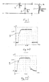
- FIG. 1 this is a circuit diagram of an arrangement used to stimulate the coil 1 of a solenoid of a DCV.
- the solenoid coil is connected across points B and C of the circuit arrangement, and a voltage of +24v is applied to point A and 0v to point D so that current passes through the coil via a diode 2, reference numeral 3 designating a flywheel diode connected between points B and C.
- the voltage is supplied for long enough for the armature 4 of the solenoid to be moved sufficiently and typically the current through the solenoid coil reaches a value of 600mA. In operation, the DCV would then be in a latched condition.
- a clip-over DC current probe was placed at points A and B of the circuit arrangement and the electrical characteristics at these points were captured on an oscilloscope and screen plots of the waveforms of current against time were taken.
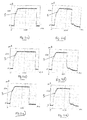
- Figs. 2a ) - n) show such screen plots under different conditions, in each case current in mA being shown against time in ms.
- Figs. 2a) and 2b ) show the waveforms observed at points A and B respectively with a void around the armature 4 of the DCV filled with free air and no hydraulic pressure applied against the armature.
- Figs. 2c) and 2d show the waveforms observed at points A and B respectively with a void around the armature 4 filled with air and an applied hydraulic pressure against the armature of 300bars.
- Figs. 2e) and 2f show the waveforms observed at points A and B respectively with a void around the armature 4 filled with oil and no hydraulic pressure applied against the armature.
- Figs. 2g) and 2h show the waveforms at points A and B respectively with a void around the armature 4 filled with oil and an applied hydraulic pressure against the armature of 300bars.
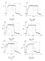
- Figs. 2i) and 2j show the waveforms which occurred at point B when the armature 4 was made to have a zero displacement with free air around the armature and no hydraulic pressure applied against the armature and free air around the armature with an applied hydraulic pressure against the armature of 320bars respectively. It will be noted that there is no discernible jump or kick 5 in either of these waveforms.
- Figs. 2k) and 2l show the waveforms which occurred at point B when the armature movement of the coil is set for a full travel of 0.15 - 0.25mm displacement with free air around the armature 4 and no hydraulic pressure applied against the armature and free air with an applied hydraulic pressure against the armature of 320bars respectively.
- Figs. 2i) and 2j show the waveforms which occurred at point B when the armature 4 was made to have a zero displacement with free air around the armature and no hydraulic pressure applied against the armature and free air around the armature with an applied hydraulic pressure against the
- DCV solenoid coil current signature data acquisition hardware and associated software are implemented within a subsea modular pod comprising a subsea control module (SCM) with a subsea electronics module (SEM).
- SCM subsea control module
- SEM subsea electronics module
- HCM hydraulic control module
- the control signals are processed by the SEM 7 which then controls electrically operated, hydraulic directional control valves (DCVs) D1 - Dn in the HCM 8 which in turn operate a multiplicity of hydraulic devices such as actuators for controlling a subsea hydrocarbon production well.
- the subsea control system is centralised within a well tree, the SCM 6 being connected to the umbilical 9 via a distribution unit 11 which provides the electric power and control signals to the SEM 7 via a cable 12 and hydraulic power to the HCM 8 via a feed 13.
- the SEM 7 controls the DCVs D1 - Dn in the HCM 8 via a cable 14.
- the SEM 7 samples the actuation currents of the solenoids of DCVs D1 - Dn as described above and stores a sampled and digitised coil actuation current profile for each of the DCVs in the memory of a local processing core 15 where the data can be assessed for armature movement and from where the data can be retrieved and sent to the MCS 10 for operator display and scrutineering.
Landscapes
- Engineering & Computer Science (AREA)
- Physics & Mathematics (AREA)
- Geology (AREA)
- Life Sciences & Earth Sciences (AREA)
- Electromagnetism (AREA)
- Mining & Mineral Resources (AREA)
- General Engineering & Computer Science (AREA)
- Power Engineering (AREA)
- Environmental & Geological Engineering (AREA)
- Fluid Mechanics (AREA)
- General Life Sciences & Earth Sciences (AREA)
- Geochemistry & Mineralogy (AREA)
- Mechanical Engineering (AREA)
- General Physics & Mathematics (AREA)
- Magnetically Actuated Valves (AREA)
Description
- The present invention relates to monitoring a solenoid, in particular a solenoid of a directional control valve (DCV) in a subsea hydrocarbon production control system. A DCV is an electro-mechanical device which is operated by stimulation of the coil of an electrical solenoid which induces a movement in an armature which in turn controls a fluid flow, such as a hydraulic flow.
- DCVs are employed within oil and gas industry subsea production control systems (PCSs) to control hydraulic function lines that are in turn used to open and close subsea hydraulic valves on PCS trees and manifolds. Hydraulic valve operation is fundamental to a subsea PCS and much design focus has been placed on ensuring that valve operations can be assured. A subsea PCS is inaccessible once deployed, very expensive to recover and critical to revenue stream (once operational).
- Therefore, a subsea PCS incorporates telemetry functions to enable DCV and associated hydraulic valve operations to be remotely monitored. PCS telemetry enables problems to be diagnosed and future problems predicted and circumvented so that recovery can be scheduled into maintenance programmes, weather windows and seasonal access windows. Any enhancement of the diagnostic capability of a PCS is therefore important.
-
US-A-4798247 (by virtue of its reference toUS-A-4321946 ) discloses a method and a system having the pre-characterising features ofclaims 1 and 3. - According to the present invention from one aspect, there is provided a method of monitoring a solenoid of a directional control valve in a subsea hydrocarbon production control system, the directional control valve being associated with a subsea control module of a subsea well and the solenoid having a coil and an armature for actuating the valve, the method comprising: applying a voltage across the coil for moving the armature; and sensing an actuation current through the coil to produce an indication of if and when the armature is moved, wherein both the voltage is applied by and the current is sensed by means in a subsea electronics module of the subsea control module, said indication being sent to a topside installation, characterised in that: the subsea electronics module samples the actuation current and stores a sampled and digitised actuation current profile of the directional control valve in the memory of a local processing core where the data is assessed for armature movement and from where the data is retrieved and sent to the topside installation for operator display and scrutineering.
- According to the present invention from another aspect, there is provided a subsea hydrocarbon production control system, comprising a subsea control module of a well, the control module being associated with at least one directional control valve having a solenoid which has a coil and an armature for actuating the valve, the system including means for applying a voltage across the coil for moving the armature; and means for sensing an actuation current through the coil to produce an indication of if and when the armature is moved, wherein said voltage applying means and said current sensing means are in a subsea electronics module of the subsea control module, there being means for sending said indication to a topside installation, characterised in that: the subsea electronics module is configured to sample the actuation current and to store a sampled and digitised actuation current profile of the directional control valve in the memory of a local processing core which is configured to assess the data for armature movement and which is configured to retrieve the data there from and to send it to the topside installation for operator display and scrutineering.
-
-
Fig. 1 shows a circuit arrangement for stimulating the coil of a solenoid of a DCV of a subsea hydrocarbon production system; -
Figs. 2a) - 2n ) show plots of current against time during the stimulation of the coil of such a solenoid under different conditions; and -
Fig. 3 is a schematic diagram of an embodiment of a production control system according to the invention. - When the coil of a DCV solenoid is initially stimulated with a fixed DC voltage across it, the current profile provides a distinctive signature of the valve. The current profile exponential characteristics for a solenoid coil are readily predictable from the solenoid coil's inductance and resistance, but a DCV solenoid coil's current characteristic with a moving armature displays a distinctive jump (kick in the waveform) at the point when the armature moves in response to stimulation of the coil. The distinctive jump or kick provides a unique signature of the DCV and can be used to characterise, evaluate and diagnose armature movement (or lack of movement).
- Referring first to
Fig. 1 , this is a circuit diagram of an arrangement used to stimulate the coil 1 of a solenoid of a DCV. The solenoid coil is connected across points B and C of the circuit arrangement, and a voltage of +24v is applied to point A and 0v to point D so that current passes through the coil via adiode 2,reference numeral 3 designating a flywheel diode connected between points B and C. The voltage is supplied for long enough for the armature 4 of the solenoid to be moved sufficiently and typically the current through the solenoid coil reaches a value of 600mA. In operation, the DCV would then be in a latched condition. - To monitor a typical Vetco Gray Controls Limited DCV under different conditions, a clip-over DC current probe was placed at points A and B of the circuit arrangement and the electrical characteristics at these points were captured on an oscilloscope and screen plots of the waveforms of current against time were taken.
-
Figs. 2a ) - n) show such screen plots under different conditions, in each case current in mA being shown against time in ms. -
Figs. 2a) and 2b ) show the waveforms observed at points A and B respectively with a void around the armature 4 of the DCV filled with free air and no hydraulic pressure applied against the armature. -
Figs. 2c) and 2d ) show the waveforms observed at points A and B respectively with a void around the armature 4 filled with air and an applied hydraulic pressure against the armature of 300bars. -
Figs. 2e) and 2f ) show the waveforms observed at points A and B respectively with a void around the armature 4 filled with oil and no hydraulic pressure applied against the armature. -
Figs. 2g) and 2h ) show the waveforms at points A and B respectively with a void around the armature 4 filled with oil and an applied hydraulic pressure against the armature of 300bars. - It will be noted in the above waveforms that, as the current increases up to 600mA, there is a distinct kick or jump 5 in the waveform - this occurring at the point when the armature 4 moves in response to stimulation of the solenoid coil 1. An instantaneous drop in the current at turn-off of the voltage (when measurements are taken at point A) is indicative of correct operation of the
flywheel diode 3. - Also, possible movement of the armature 4 was adjusted in the coil to demonstrate the effects of over-travel, full travel and restricted travel on the electrical characteristics at point B.
-
Figs. 2i) and 2j ) show the waveforms which occurred at point B when the armature 4 was made to have a zero displacement with free air around the armature and no hydraulic pressure applied against the armature and free air around the armature with an applied hydraulic pressure against the armature of 320bars respectively. It will be noted that there is no discernible jump orkick 5 in either of these waveforms.
Figs. 2k) and 2l ) show the waveforms which occurred at point B when the armature movement of the coil is set for a full travel of 0.15 - 0.25mm displacement with free air around the armature 4 and no hydraulic pressure applied against the armature and free air with an applied hydraulic pressure against the armature of 320bars respectively.
Figs. 2m) and 2n ) show the waveforms which occurred when the armature 4 is set to have a maximum possible displacement (so-called over-travel) with free air around the armature and no hydraulic pressure applied against the armature and free air with an applied hydraulic pressure against the armature of 320bars respectively.
It will be noted that inFigs. 2k) - 2n ) a discernible jump orkick 5 appears as inFigs. 2a) - 2h ).
In practice, and referring toFig. 3 , which shows schematically a subsea hydrocarbon production control system incorporating the invention, DCV solenoid coil current signature data acquisition hardware and associated software are implemented within a subsea modular pod comprising a subsea control module (SCM) with a subsea electronics module (SEM). Profile display, diagnostics and health monitoring software are implemented in a topside master control station (MCS). More particularly, in a subsea control module (SCM) 6 there is a subsea electronics module (SEM) 7 and a hydraulic control module (HCM) 8. The SCM 6 is fed by an umbilical 9 from a topside master control station (MCS) 10, e.g. at a surface platform, with electric power, control signals and hydraulic power. The control signals are processed by the SEM 7 which then controls electrically operated, hydraulic directional control valves (DCVs) D1 - Dn in theHCM 8 which in turn operate a multiplicity of hydraulic devices such as actuators for controlling a subsea hydrocarbon production well. The subsea control system is centralised within a well tree, the SCM 6 being connected to the umbilical 9 via a distribution unit 11 which provides the electric power and control signals to the SEM 7 via acable 12 and hydraulic power to theHCM 8 via afeed 13. The SEM 7 controls the DCVs D1 - Dn in theHCM 8 via acable 14. - Also, the SEM 7 samples the actuation currents of the solenoids of DCVs D1 - Dn as described above and stores a sampled and digitised coil actuation current profile for each of the DCVs in the memory of a
local processing core 15 where the data can be assessed for armature movement and from where the data can be retrieved and sent to the MCS 10 for operator display and scrutineering. - Measuring and recording the solenoid coil actuation current signature provides a means of remotely monitoring the following DCV characteristics:-
- DCV armature seizure - i.e. no travel detected following stimulation of the DCV solenoid coil.
- DCV armature travel - i.e. distance travelled by the armature upon stimulation of the DCV solenoid coil.
- DCV armature travel change over product life. The DCV solenoid coil actuation current signature (in the field) can be compared with that obtained as a reference during an equipment factory acceptance test to assess potential degradation and change of the valve's performance over the operational life of the DCV.
- DCV valve operation - i.e. good/bad assessment. Automatic interpretation of the DCV solenoid coil actuation current signature (by the SEM) enables a good/bad valve operation indication to be relayed to the remote user. Full signature retrieval can be requested (if a bad valve operation is flagged) for more detailed evaluation/scrutineering.
- Solenoid coil current turn off signature can also be employed to establish that the solenoid coil flywheel diode is in circuit and operational.
Claims (4)
- A method of monitoring a solenoid of a directional control valve (D1) in a subsea hydrocarbon production control system, the directional control valve being associated with a subsea control module (6) of a subsea well and the solenoid having a coil and an armature for actuating the valve, the method comprising: applying a voltage across the coil for moving the armature; and sensing an actuation current through the coil to produce an indication of if and when the armature is moved, wherein both the voltage is applied by and the current is sensed by means in a subsea electronics module (7) of the subsea control module, said indication being sent to a topside installation (10), characterised in that: the subsea electronics module samples the actuation current and stores a sampled and digitised actuation current profile of the directional control valve in the memory of a local processing core (15) where the data is assessed for armature movement and from where the data is retrieved and sent to the topside installation for operator display and scrutineering.
- A method according to claim 1, wherein said subsea control module (6) is at a tree of the subsea well.
- A subsea hydrocarbon production control system, comprising a subsea control module (6) of a well, the control module being associated with at least one directional control valve (D1) having a solenoid which has a coil and an armature for actuating the valve, the system including means for applying a voltage across the coil for moving the armature; and means for sensing an actuation current through the coil to produce an indication of if and when the armature is moved, wherein said voltage applying means and said current sensing means are in a subsea electronics module (7) of the subsea control module, there being means for sending said indication to a topside installation (10), characterised in that: the subsea electronics module is configured to sample the actuation current and to store a sampled and digitised actuation current profile of the directional control valve in the memory of a local processing core (15) which is configured to assess the data for armature movement and which is configured to retrieve the data therefrom and to send it to the topside installation for operator display and scrutineering.
- A system according to claim 3, wherein said subsea control module (6) is at a tree of the subsea well.
Applications Claiming Priority (1)
| Application Number | Priority Date | Filing Date | Title |
|---|---|---|---|
| GB0720690A GB2453947A (en) | 2007-10-23 | 2007-10-23 | Solenoid coil current used in armature movement monitoring |
Publications (3)
| Publication Number | Publication Date |
|---|---|
| EP2053289A2 EP2053289A2 (en) | 2009-04-29 |
| EP2053289A3 EP2053289A3 (en) | 2011-09-21 |
| EP2053289B1 true EP2053289B1 (en) | 2017-12-13 |
Family
ID=38829720
Family Applications (1)
| Application Number | Title | Priority Date | Filing Date |
|---|---|---|---|
| EP08166219.9A Active EP2053289B1 (en) | 2007-10-23 | 2008-10-09 | Monitoring a solenoid of a directional control valve |
Country Status (6)
| Country | Link |
|---|---|
| US (1) | US8122963B2 (en) |
| EP (1) | EP2053289B1 (en) |
| AU (1) | AU2008230043B2 (en) |
| BR (1) | BRPI0804453A8 (en) |
| GB (1) | GB2453947A (en) |
| NO (1) | NO2053289T3 (en) |
Families Citing this family (22)
| Publication number | Priority date | Publication date | Assignee | Title |
|---|---|---|---|---|
| WO2009146206A2 (en) * | 2008-04-18 | 2009-12-03 | Schlumberger Canada Limited | Subsea tree safety control system |
| US8511389B2 (en) * | 2010-10-20 | 2013-08-20 | Vetco Gray Inc. | System and method for inductive signal and power transfer from ROV to in riser tools |
| EP2447798B1 (en) * | 2010-10-26 | 2014-07-23 | Vetco Gray Controls Limited | Testing a control system including a valve |
| EP2469015B2 (en) † | 2010-12-22 | 2018-11-21 | GE Oil & Gas UK Limited | Prognostics of well data |
| CN102121965B (en) * | 2011-01-12 | 2013-04-17 | 宁波海锐自动化科技有限公司 | Overtravel testing device |
| EP2489826B1 (en) | 2011-02-18 | 2018-06-06 | GE Oil & Gas UK Limited | Testing a solenoid of a directional control valve |
| EP2492931B1 (en) | 2011-02-22 | 2014-06-18 | Vetco Gray Controls Limited | Energizing a coil of a solenoid of a directional control valve |
| US8823390B2 (en) | 2011-06-15 | 2014-09-02 | Eaton Corporation | Solenoid-operated valve and method of monitoring same |
| EP2751455A4 (en) | 2011-08-29 | 2015-08-19 | Exxonmobil Upstream Res Co | System and method for high speed hydraulic actuation |
| CN103389461B (en) * | 2013-07-25 | 2016-03-02 | 德力西电气有限公司 | A kind of circuit breaker electronic release containing isolating switch life testing function |
| EP2853682A1 (en) * | 2013-09-25 | 2015-04-01 | Siemens Aktiengesellschaft | Subsea enclosure system for disposal of generated heat |
| US9038760B1 (en) | 2013-11-12 | 2015-05-26 | Ford Global Technologies, Llc | Active front steering system lock |
| US9394848B2 (en) | 2014-01-13 | 2016-07-19 | Caterpillar Inc. | End-of current trim for common rail fuel system |
| US10253900B2 (en) * | 2014-05-27 | 2019-04-09 | Continental Automotive Systems, Inc. | Latching valve assembly having position sensing |
| GB2546658B (en) | 2014-12-29 | 2021-05-12 | Halliburton Energy Services Inc | Downhole solenoid acutator drive system |
| US9567002B2 (en) | 2015-03-05 | 2017-02-14 | Ford Global Technologies, Llc | Steering systems including locking controls for a motor vehicle, and motor vehicles including steering systems |
| US20180045375A1 (en) * | 2016-08-10 | 2018-02-15 | Honeywell International Inc. | Smart solenoid control system |
| MX2019010737A (en) | 2017-03-07 | 2020-01-20 | Asco Lp | A device and method for anticipating failure in a solenoid valve for a manifold assembly. |
| NO343693B1 (en) * | 2017-06-14 | 2019-05-13 | Fmc Kongsberg Subsea As | Electric power and communication module |
| CN110475995B (en) | 2017-09-18 | 2021-01-08 | 阿斯科公司 | Apparatus and method for monitoring response time in valve manifold assemblies |
| US11642243B2 (en) * | 2018-12-10 | 2023-05-09 | Alcon Inc. | Methods of solenoid valve control optimization |
| CN116045054B (en) * | 2022-11-18 | 2026-01-02 | 中国核工业第五建设有限公司 | A single-unit commissioning control system for an electric valve |
Family Cites Families (30)
| Publication number | Priority date | Publication date | Assignee | Title |
|---|---|---|---|---|
| USRE30110E (en) * | 1975-09-24 | 1979-10-09 | Fail-safe safety cut-off valve for a fluid well | |
| US4321946A (en) * | 1980-03-31 | 1982-03-30 | Paulos Louis B | Armature position monitoring and control device |
| GB2110373B (en) * | 1981-11-13 | 1985-07-24 | Louis Bertrand Paulos | Sensing position of solenoid armatures |
| DE3624231A1 (en) * | 1986-07-18 | 1988-01-28 | Honeywell Regelsysteme Gmbh | Method for indicating solenoid-valve operation and a circuit arrangement for carrying out the method |
| US4798247A (en) * | 1987-07-15 | 1989-01-17 | Otis Engineering Corporation | Solenoid operated safety valve and submersible pump system |
| US4886114A (en) * | 1988-03-18 | 1989-12-12 | Otis Engineering Corporation | Electric surface controlled subsurface valve system |
| DE3843138A1 (en) * | 1988-12-22 | 1990-06-28 | Bosch Gmbh Robert | METHOD OF CONTROLLING AND DETECTING THE MOVEMENT OF AN ARMATURE OF AN ELECTROMAGNETIC SWITCHING DEVICE |
| JP3105007B2 (en) * | 1990-07-06 | 2000-10-30 | ジヤトコ・トランステクノロジー株式会社 | Failure detection device for solenoid valve |
| GB9102789D0 (en) * | 1991-02-09 | 1991-03-27 | Norgren Martonair Ltd | Armature movement detection circuit |
| US5481187A (en) * | 1991-11-29 | 1996-01-02 | Caterpillar Inc. | Method and apparatus for determining the position of an armature in an electromagnetic actuator |
| US5424637A (en) * | 1993-03-15 | 1995-06-13 | Caterpillar Inc. | Method and apparatus for determining the position of an armature in an electromagnetic actuator using observer theory |
| US5583434A (en) * | 1993-07-20 | 1996-12-10 | Martin Marietta Energy Systems, Inc. | Method and apparatus for monitoring armature position in direct-current solenoids |
| US5796261A (en) * | 1995-05-08 | 1998-08-18 | Chrysler Corporation | Method and device for detecting solenoid actuation |
| GB2306679B (en) * | 1995-11-03 | 2000-05-17 | Motorola Ltd | Method for detecting closure of a solenoid coil |
| US5808471A (en) * | 1996-08-02 | 1998-09-15 | Ford Global Technologies, Inc. | Method and system for verifying solenoid operation |
| US5784245A (en) * | 1996-11-27 | 1998-07-21 | Motorola Inc. | Solenoid driver and method for determining solenoid operational status |
| US6111514A (en) * | 1996-12-18 | 2000-08-29 | Kelsey-Hayes Company | Solenoid fail-safe using current feedback as a diagnostic input |
| DE19742038A1 (en) * | 1997-09-24 | 1999-03-25 | Wabco Gmbh | Solenoid valve state detection method |
| US5942892A (en) * | 1997-10-06 | 1999-08-24 | Husco International, Inc. | Method and apparatus for sensing armature position in direct current solenoid actuators |
| US6577133B1 (en) * | 1998-07-20 | 2003-06-10 | Kelsey-Hayes Company | Inductive measurement of armature travel within a solenoid valve |
| US6476599B1 (en) * | 1999-03-25 | 2002-11-05 | Siemens Automotive Corporation | Sensorless method to determine the static armature position in an electronically controlled solenoid device |
| US6211665B1 (en) * | 1999-04-13 | 2001-04-03 | Alliedsignal Inc. | Solenoid motion detection circuit |
| US6326898B1 (en) * | 2000-10-24 | 2001-12-04 | Xerox Corporation | Solenoid plunger position detection algorithm |
| US7012315B1 (en) * | 2000-11-01 | 2006-03-14 | Micron Technology, Inc. | Frame scale package using contact lines through the elements |
| US6917203B1 (en) * | 2001-09-07 | 2005-07-12 | The United States Of America As Represented By The Administrator Of The National Aeronautics And Space Administration | Current signature sensor |
| US6845300B2 (en) * | 2002-01-07 | 2005-01-18 | Ford Global Technologies, Llc | Control methods for electromagnetic valve actuators |
| US7595971B2 (en) * | 2005-06-15 | 2009-09-29 | Honeywell International Inc. | Sensing armature motion in high-speed solenoids |
| US7511478B2 (en) * | 2005-08-03 | 2009-03-31 | Honeywell International Inc. | Sensorless position measurement method for solenoid-based actuation devices using inductance variation |
| US7483253B2 (en) * | 2006-05-30 | 2009-01-27 | Caterpillar Inc. | Systems and methods for detecting solenoid armature movement |
| US7405917B2 (en) * | 2006-06-16 | 2008-07-29 | Festo Ag & Co. | Method and apparatus for monitoring and determining the functional status of an electromagnetic valve |
-
2007
- 2007-10-23 GB GB0720690A patent/GB2453947A/en not_active Withdrawn
-
2008
- 2008-10-09 EP EP08166219.9A patent/EP2053289B1/en active Active
- 2008-10-09 NO NO08166219A patent/NO2053289T3/no unknown
- 2008-10-22 BR BRPI0804453A patent/BRPI0804453A8/en not_active Application Discontinuation
- 2008-10-22 US US12/256,068 patent/US8122963B2/en active Active
- 2008-10-22 AU AU2008230043A patent/AU2008230043B2/en active Active
Non-Patent Citations (1)
| Title |
|---|
| None * |
Also Published As
| Publication number | Publication date |
|---|---|
| BRPI0804453A2 (en) | 2009-06-30 |
| US8122963B2 (en) | 2012-02-28 |
| GB2453947A (en) | 2009-04-29 |
| EP2053289A3 (en) | 2011-09-21 |
| AU2008230043B2 (en) | 2014-09-18 |
| GB0720690D0 (en) | 2007-12-05 |
| US20090107682A1 (en) | 2009-04-30 |
| NO2053289T3 (en) | 2018-05-12 |
| EP2053289A2 (en) | 2009-04-29 |
| AU2008230043A1 (en) | 2009-05-07 |
| BRPI0804453A8 (en) | 2016-04-05 |
Similar Documents
| Publication | Publication Date | Title |
|---|---|---|
| US8122963B2 (en) | Monitoring a solenoid of a directional control valve | |
| US20130054034A1 (en) | Method, device and system for monitoring subsea components | |
| US8515880B2 (en) | Condition monitoring of an underwater facility | |
| US20220349429A1 (en) | Smart Valve with Integrated Electronics | |
| CN101750531B (en) | Movement detection circuit of solenoid shear seal valve on subsea pressure control system | |
| CN103308288A (en) | Diagnosis device of valve and diagnosis method applying same | |
| EP3970086B1 (en) | System and method for managing wellsite event detection | |
| CN101799365A (en) | The performance monitoring of aircraft pneumatic control valves and forecast | |
| WO2010138318A1 (en) | System and method for monitoring subsea valves | |
| US12467332B2 (en) | Convertible slickline stuffing box | |
| US20080158005A1 (en) | Method and apparatus for locating faults in wired drill pipe | |
| Kezunovic et al. | Automated circuit breaker monitoring and analysis | |
| WO2024072776A1 (en) | Convertible slickline stuffing box | |
| US9828821B2 (en) | Testing a solenoid of a directional control valve | |
| EP2447798B1 (en) | Testing a control system including a valve | |
| CN111852839B (en) | Device and method for monitoring and predicting faults of electric submersible pump unit | |
| US20140082304A1 (en) | Monitoring a subsea installation | |
| WO2006059133A1 (en) | Measurement of corrosivity | |
| Nicolaou et al. | Intelligent, sensor-based condition monitoring of transformer stations in the distribution network | |
| EP2469015B2 (en) | Prognostics of well data | |
| WO2022011375A1 (en) | Blowout preventer system with data playback |
Legal Events
| Date | Code | Title | Description |
|---|---|---|---|
| PUAI | Public reference made under article 153(3) epc to a published international application that has entered the european phase |
Free format text: ORIGINAL CODE: 0009012 |
|
| AK | Designated contracting states |
Kind code of ref document: A2 Designated state(s): AT BE BG CH CY CZ DE DK EE ES FI FR GB GR HR HU IE IS IT LI LT LU LV MC MT NL NO PL PT RO SE SI SK TR |
|
| AX | Request for extension of the european patent |
Extension state: AL BA MK RS |
|
| PUAL | Search report despatched |
Free format text: ORIGINAL CODE: 0009013 |
|
| AK | Designated contracting states |
Kind code of ref document: A3 Designated state(s): AT BE BG CH CY CZ DE DK EE ES FI FR GB GR HR HU IE IS IT LI LT LU LV MC MT NL NO PL PT RO SE SI SK TR |
|
| AX | Request for extension of the european patent |
Extension state: AL BA MK RS |
|
| RIC1 | Information provided on ipc code assigned before grant |
Ipc: F16K 37/00 20060101ALI20110812BHEP Ipc: E21B 34/06 20060101AFI20110812BHEP Ipc: H01F 7/18 20060101ALI20110812BHEP |
|
| 17P | Request for examination filed |
Effective date: 20120309 |
|
| AKX | Designation fees paid |
Designated state(s): DE FR GB NO |
|
| RAP1 | Party data changed (applicant data changed or rights of an application transferred) |
Owner name: GE OIL & GAS UK LIMITED |
|
| REG | Reference to a national code |
Ref country code: DE Ref legal event code: R079 Ref document number: 602008053317 Country of ref document: DE Free format text: PREVIOUS MAIN CLASS: F16K0037000000 Ipc: E21B0033035000 |
|
| RIC1 | Information provided on ipc code assigned before grant |
Ipc: F16K 37/00 20060101ALI20170623BHEP Ipc: E21B 33/035 20060101AFI20170623BHEP Ipc: F16K 31/06 20060101ALI20170623BHEP Ipc: H01F 7/18 20060101ALI20170623BHEP |
|
| GRAP | Despatch of communication of intention to grant a patent |
Free format text: ORIGINAL CODE: EPIDOSNIGR1 |
|
| GRAJ | Information related to disapproval of communication of intention to grant by the applicant or resumption of examination proceedings by the epo deleted |
Free format text: ORIGINAL CODE: EPIDOSDIGR1 |
|
| GRAP | Despatch of communication of intention to grant a patent |
Free format text: ORIGINAL CODE: EPIDOSNIGR1 |
|
| INTG | Intention to grant announced |
Effective date: 20170816 |
|
| INTG | Intention to grant announced |
Effective date: 20170825 |
|
| GRAS | Grant fee paid |
Free format text: ORIGINAL CODE: EPIDOSNIGR3 |
|
| GRAA | (expected) grant |
Free format text: ORIGINAL CODE: 0009210 |
|
| AK | Designated contracting states |
Kind code of ref document: B1 Designated state(s): DE FR GB NO |
|
| REG | Reference to a national code |
Ref country code: GB Ref legal event code: FG4D |
|
| REG | Reference to a national code |
Ref country code: DE Ref legal event code: R096 Ref document number: 602008053317 Country of ref document: DE |
|
| REG | Reference to a national code |
Ref country code: NO Ref legal event code: T2 Effective date: 20171213 |
|
| REG | Reference to a national code |
Ref country code: DE Ref legal event code: R097 Ref document number: 602008053317 Country of ref document: DE |
|
| REG | Reference to a national code |
Ref country code: FR Ref legal event code: PLFP Year of fee payment: 11 |
|
| PLBE | No opposition filed within time limit |
Free format text: ORIGINAL CODE: 0009261 |
|
| STAA | Information on the status of an ep patent application or granted ep patent |
Free format text: STATUS: NO OPPOSITION FILED WITHIN TIME LIMIT |
|
| 26N | No opposition filed |
Effective date: 20180914 |
|
| PGFP | Annual fee paid to national office [announced via postgrant information from national office to epo] |
Ref country code: NO Payment date: 20250925 Year of fee payment: 18 |
|
| PGFP | Annual fee paid to national office [announced via postgrant information from national office to epo] |
Ref country code: GB Payment date: 20250923 Year of fee payment: 18 |
|
| PGFP | Annual fee paid to national office [announced via postgrant information from national office to epo] |
Ref country code: FR Payment date: 20250924 Year of fee payment: 18 |
|
| PGFP | Annual fee paid to national office [announced via postgrant information from national office to epo] |
Ref country code: DE Payment date: 20250923 Year of fee payment: 18 |