EP2052903A2 - Folding seats - Google Patents
Folding seats Download PDFInfo
- Publication number
- EP2052903A2 EP2052903A2 EP08252715A EP08252715A EP2052903A2 EP 2052903 A2 EP2052903 A2 EP 2052903A2 EP 08252715 A EP08252715 A EP 08252715A EP 08252715 A EP08252715 A EP 08252715A EP 2052903 A2 EP2052903 A2 EP 2052903A2
- Authority
- EP
- European Patent Office
- Prior art keywords
- backrest
- seat base
- seat
- over
- spring means
- Prior art date
- Legal status (The legal status is an assumption and is not a legal conclusion. Google has not performed a legal analysis and makes no representation as to the accuracy of the status listed.)
- Granted
Links
Images


Classifications
-
- B—PERFORMING OPERATIONS; TRANSPORTING
- B60—VEHICLES IN GENERAL
- B60N—SEATS SPECIALLY ADAPTED FOR VEHICLES; VEHICLE PASSENGER ACCOMMODATION NOT OTHERWISE PROVIDED FOR
- B60N2/00—Seats specially adapted for vehicles; Arrangement or mounting of seats in vehicles
- B60N2/24—Seats specially adapted for vehicles; Arrangement or mounting of seats in vehicles for particular purposes or particular vehicles
- B60N2/30—Non-dismountable or dismountable seats storable in a non-use position, e.g. foldable spare seats
- B60N2/3002—Non-dismountable or dismountable seats storable in a non-use position, e.g. foldable spare seats back-rest movements
- B60N2/3004—Non-dismountable or dismountable seats storable in a non-use position, e.g. foldable spare seats back-rest movements by rotation only
- B60N2/3009—Non-dismountable or dismountable seats storable in a non-use position, e.g. foldable spare seats back-rest movements by rotation only about transversal axis
- B60N2/3013—Non-dismountable or dismountable seats storable in a non-use position, e.g. foldable spare seats back-rest movements by rotation only about transversal axis the back-rest being hinged on the vehicle frame
-
- B—PERFORMING OPERATIONS; TRANSPORTING
- B60—VEHICLES IN GENERAL
- B60N—SEATS SPECIALLY ADAPTED FOR VEHICLES; VEHICLE PASSENGER ACCOMMODATION NOT OTHERWISE PROVIDED FOR
- B60N2/00—Seats specially adapted for vehicles; Arrangement or mounting of seats in vehicles
- B60N2/02—Seats specially adapted for vehicles; Arrangement or mounting of seats in vehicles the seat or part thereof being movable, e.g. adjustable
- B60N2/20—Seats specially adapted for vehicles; Arrangement or mounting of seats in vehicles the seat or part thereof being movable, e.g. adjustable the back-rest being tiltable, e.g. to permit easy access
- B60N2/206—Seats specially adapted for vehicles; Arrangement or mounting of seats in vehicles the seat or part thereof being movable, e.g. adjustable the back-rest being tiltable, e.g. to permit easy access to a position in which it can be used as a support for objects, e.g. as a tray
-
- B—PERFORMING OPERATIONS; TRANSPORTING
- B60—VEHICLES IN GENERAL
- B60N—SEATS SPECIALLY ADAPTED FOR VEHICLES; VEHICLE PASSENGER ACCOMMODATION NOT OTHERWISE PROVIDED FOR
- B60N2/00—Seats specially adapted for vehicles; Arrangement or mounting of seats in vehicles
- B60N2/24—Seats specially adapted for vehicles; Arrangement or mounting of seats in vehicles for particular purposes or particular vehicles
- B60N2/30—Non-dismountable or dismountable seats storable in a non-use position, e.g. foldable spare seats
- B60N2/3038—Cushion movements
- B60N2/304—Cushion movements by rotation only
- B60N2/3045—Cushion movements by rotation only about transversal axis
- B60N2/305—Cushion movements by rotation only about transversal axis the cushion being hinged on the vehicle frame
-
- B—PERFORMING OPERATIONS; TRANSPORTING
- B60—VEHICLES IN GENERAL
- B60N—SEATS SPECIALLY ADAPTED FOR VEHICLES; VEHICLE PASSENGER ACCOMMODATION NOT OTHERWISE PROVIDED FOR
- B60N2/00—Seats specially adapted for vehicles; Arrangement or mounting of seats in vehicles
- B60N2/24—Seats specially adapted for vehicles; Arrangement or mounting of seats in vehicles for particular purposes or particular vehicles
- B60N2/30—Non-dismountable or dismountable seats storable in a non-use position, e.g. foldable spare seats
- B60N2/3088—Non-dismountable or dismountable seats storable in a non-use position, e.g. foldable spare seats characterised by the mechanical link
-
- B—PERFORMING OPERATIONS; TRANSPORTING
- B60—VEHICLES IN GENERAL
- B60N—SEATS SPECIALLY ADAPTED FOR VEHICLES; VEHICLE PASSENGER ACCOMMODATION NOT OTHERWISE PROVIDED FOR
- B60N2/00—Seats specially adapted for vehicles; Arrangement or mounting of seats in vehicles
- B60N2/24—Seats specially adapted for vehicles; Arrangement or mounting of seats in vehicles for particular purposes or particular vehicles
- B60N2/38—Seats specially adapted for vehicles; Arrangement or mounting of seats in vehicles for particular purposes or particular vehicles specially constructed for use on tractors or like off-road vehicles
Definitions
- This invention relates to folding seats and in particular to such seats for use as passenger seats in agricultural tractors or similar vehicles.
- a folding seat having a support structure and a backrest and seat base pivotally mounted on the support structure for pivoting between a seating position with the seat base extending generally horizontal and the backrest generally vertically, a stored position with the base and backrest both extending generally vertical, and a table position with base and backrest both extending generally horizontally, first over-centre spring means acting on the seat base to bias the seat base towards its generally horizontal position or its generally vertical position depending on which side of the first spring means over-centre position the base is located, and second over-centre spring means acting on the backrest to bias the backrest towards its generally vertical position or its generally horizontal position depending on which side of the second spring means over-centre position the backrest is located.
- the over-centre spring means not only tend to hold the backrest and seat base in their generally vertical and horizontal positions but also provide assistance for moving the backrest and seat base between these positions as they move through the over-centre positions of the spring means. This reduces any tendency of the backrest and seat base to rattle and avoids any need to have any locking means to physically lock the backrest or seat base in either the vertical or horizontal position. Also one handed movement of the backrest and seat base is possible.
- first over-centre spring means acts between the seat base and the support structure and the second over-centre spring means acts between the seat base and the backrest.
- This construction means that the backrest and seat base can be swung, under the action of the first over-centre spring means, between the vertical stored position and the horizontal table position whilst held together as a pair by the second over-centre spring means.
- first over-centre spring means acts between the seat base and the support structure and the second over-centre spring means acts between the seat base and the support structure.
- the over-centre spring means may each comprise a gas spring or a coil or compression spring.
- first stop means are provided to limit the movements of the seat base and backrest away from each other to define the position of the backrest when in the seating position. This arrangement ensures that the first over-centre spring means is not continually stressed by being required to maintain the backrest at the required angle for the seating position.
- Second stop means are also preferably provided to limit the movement of the seat base and backrest towards each other.
- the second stop means prevents the backrest and seat base from damaging each other when they are adjacent each other in the stored or table positions.
- the seat base may be provided with a first pair of mounting brackets located one at each side of the seat base which pivotally mount the seat base on the support structure and the backrest has a second pair of mounting brackets located one on each side of the backrest which pivotally mount the back rest on the support structure.
- the second over-centre centre spring means may act between one of the second pair of brackets and the seat base.
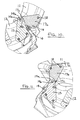
- a folding tractor passenger seat 10 has a backrest 11 and seat base 12 which are both pivotally mounted on a support structure 13.
- the support structure includes a pair of support arms 14 whose outer ends 14a each support an outwardly projecting pivot pin 14b on which both the backrest 11 and seat base 12 are mounted for pivoting about an axis Z (see Figure 2 ).
- the support structure 13 is typically mounted inside a tractor cab on an inner wall of a tractor rear wheel arch/fender to one side of the tractor driver's seat.
- the seat base 12 is provided with a pair of mounting brackets 15 located one on each side of the seat base and which are secured to the seat base by bolts 16.
- a three-piece mounting bracket 17 is provide at each side of the backrest 11 and is secured to the backrest by mounting bolts 18.
- the three-piece brackets 17 each comprise outer components 17a and an inner spacing component 17b (best seen in Figures 10 and 11 ).
- Component 17b has a stop nose 17c which, as shown in Figure 10 , cooperates with a stop surface 15a on each respective bracket 15 to limit the pivotal movement of the backrest 11 away from the seat base 12.
- the stop nose 17c cooperates with a further stop surface 15b on each respective bracket 15 to limit the movement towards each other of the backrest 11 and seat base 12.
- a first over-centre spring means 19 acts between the seat base 12 and the support structure 14.
- this over-centre spring means is a gas strut which has an outer cylinder 20 within which a piston 21 attached to a piston rod 22 (see Figure 5 ) is biased by gas retained under pressure in a chamber 23 of the gas strut. This gas pressure tends to try to extend the effective length of the gas strut at all times.
- the outer cylinder 20 of the gas strut is pivoted to the seat base by bolt 24 and the end of the piston rod 22 is pivoted to the support structure 14 by a bolt 37 via a mounting plate 25 which is bolted to the support structure 14 by a bolt 26 and is received on the pivot pin 14b where it is held captive by a nut 27.
- a second over-centre spring means 28 is provided which, in the example shown, is also of the gas strut type having an outer cylinder 29 within which a piston 30 having a piston rod 31 slides (see Figure 4 ).
- the gas strut 28 contains pressurised gas in the chamber 32 which constantly tends to increase the effect length of the gas strut.
- the outer cylinder 29 of the gas strut is pivoted on the seat base by bolt 33 and the piston rod 31 is pivoted on an extension 17c of the bracket member 17a by a bolt 34.
- the support structure 13 is provided with two projections 35 which, when the seat base is in a lower horizontal position enter apertures 36 in the seat base to help locate the seat against sideways movement.
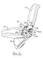
- the seat base 12 can be pivoted vertically about the pivot pins 14b by applying a force to the seat base in the direction of the arrow X over Figure 6 .
- the line of action of the gas strut 19 passes through the pivot pin 14b as shown by the line Y and this is the so-called over-centre position.
- the force applied to the seat base by the gas strut 19 tends to oppose the upward movement of the seat base whereas for positions of the seat base above the Figure 6 position the gas strut 19 assists the tractor driver to move the seat base 12 to the stored position shown in Figure 3 .
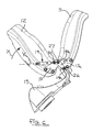
- the gas strut 19 holds the seat base 12 in its stored position.
- the gas strut 19 When the seat base 12 is pivoted away from the backrest to move towards the sitting position the gas strut 19 initially helps to support the seat base 12 as it is moved downwardly thus stopping the seat base falling immediately to the seating position. When the seat base is in the seating position the gas strut 19 holds the seat base firmly in this position.
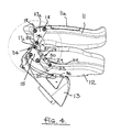
- the seat base 12 and backrest 11 can be pivoted together as a pair between a table position shown in Figures 2 and 4 (in which the back 11a of the backrest forms a table for use by the operator) and the stored position shown in Figure 3 .
- the backrest and seat base pivot together between these positions pivotal movement is under the influence of the first gas strut 19 alone with the second gas strut 28 holding the backrest and seat base together with the stop nose 17c in contact with the stop surface 15b as shown in Figure 11 .
- each spring 19,28 is located and moved inside the seat base and backrest contours as can be seen in the side views of Figures 3 to 7 .
- the tractor operator is assisted in his movement of the backrest and seat base between their various desired positions and this movement of the backrest and seat base is also controlled so that these components cannot fall unexpectantly.
- the gas struts also prevent annoying rattle of the back rest and seat base when the tractor is in use and avoid the necessity for any mechanical locking devices for locking either the seat base or backrest in their various positions. Also one handed movement of the backrest and seat base is possible.
- the gas struts could be replaced by coil springs or other spring means which apply the same forces to the backrest and seat base.
- the present invention thus provides a folding seat which is particularly suitable for use in an agricultural tractor or similar vehicle which can be easily moved between and held in its various operating positions.
Landscapes
- Engineering & Computer Science (AREA)
- Aviation & Aerospace Engineering (AREA)
- Transportation (AREA)
- Mechanical Engineering (AREA)
- Seats For Vehicles (AREA)
Abstract
Description
- This invention relates to folding seats and in particular to such seats for use as passenger seats in agricultural tractors or similar vehicles.
- There is a requirement for such seats in which the components of the seat can easily be moved between and held in their various positions.
- Thus according to the present invention there is provided a folding seat having a support structure and a backrest and seat base pivotally mounted on the support structure for pivoting between a seating position with the seat base extending generally horizontal and the backrest generally vertically, a stored position with the base and backrest both extending generally vertical, and a table position with base and backrest both extending generally horizontally, first over-centre spring means acting on the seat base to bias the seat base towards its generally horizontal position or its generally vertical position depending on which side of the first spring means over-centre position the base is located, and second over-centre spring means acting on the backrest to bias the backrest towards its generally vertical position or its generally horizontal position depending on which side of the second spring means over-centre position the backrest is located.
- The over-centre spring means not only tend to hold the backrest and seat base in their generally vertical and horizontal positions but also provide assistance for moving the backrest and seat base between these positions as they move through the over-centre positions of the spring means. This reduces any tendency of the backrest and seat base to rattle and avoids any need to have any locking means to physically lock the backrest or seat base in either the vertical or horizontal position. Also one handed movement of the backrest and seat base is possible.
- In a preferred construction the first over-centre spring means acts between the seat base and the support structure and the second over-centre spring means acts between the seat base and the backrest.
- This construction means that the backrest and seat base can be swung, under the action of the first over-centre spring means, between the vertical stored position and the horizontal table position whilst held together as a pair by the second over-centre spring means.
- In an alternative construction the first over-centre spring means acts between the seat base and the support structure and the second over-centre spring means acts between the seat base and the support structure.
- The over-centre spring means may each comprise a gas spring or a coil or compression spring.
- Preferably first stop means are provided to limit the movements of the seat base and backrest away from each other to define the position of the backrest when in the seating position. This arrangement ensures that the first over-centre spring means is not continually stressed by being required to maintain the backrest at the required angle for the seating position.
- Second stop means are also preferably provided to limit the movement of the seat base and backrest towards each other. The second stop means prevents the backrest and seat base from damaging each other when they are adjacent each other in the stored or table positions.
- The seat base may be provided with a first pair of mounting brackets located one at each side of the seat base which pivotally mount the seat base on the support structure and the backrest has a second pair of mounting brackets located one on each side of the backrest which pivotally mount the back rest on the support structure.
- In such an arrangement the second over-centre centre spring means may act between one of the second pair of brackets and the seat base.
- One embodiment of the present invention will now be described, by way of example only, with reference to the accompanying drawings in which:-
-
Figure 1 shows a front perspective view of a folding tractor passenger seat in accordance with the present invention in its seating position; -
Figure 2 shows a rear perspective view of the seat offigure 1 in its table position; -
Figure 3 shows a side view of the seat in its stored position; -
Figure 4 shows a side view of the seat in its table position; -
Figure 5 shows a side view of the seat in its seating position; -
Figure 6 shows a side view of the seat base moving between its seating and stored positions; -
Figure 7 shows a side view of the backrest and seat base moving together between their stored and table positions; -
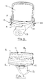
Figure 8 shows a rear view of the seat; -
Figure 9 shows a front view of the seat in its table position, and -
Figures 10 and 11 show sections on plane A-A ofFigure 8 and plane B-B ofFigure 9 respectively. - Referring to the drawings a folding
tractor passenger seat 10 has abackrest 11 andseat base 12 which are both pivotally mounted on asupport structure 13. The support structure includes a pair ofsupport arms 14 whoseouter ends 14a each support an outwardly projectingpivot pin 14b on which both thebackrest 11 andseat base 12 are mounted for pivoting about an axis Z (seeFigure 2 ). Thesupport structure 13 is typically mounted inside a tractor cab on an inner wall of a tractor rear wheel arch/fender to one side of the tractor driver's seat. - The
seat base 12 is provided with a pair ofmounting brackets 15 located one on each side of the seat base and which are secured to the seat base bybolts 16. Similarly, a three-piece mounting bracket 17 is provide at each side of thebackrest 11 and is secured to the backrest by mountingbolts 18. The three-piece brackets 17 each compriseouter components 17a and an inner spacing component 17b (best seen inFigures 10 and 11 ). Component 17b has astop nose 17c which, as shown inFigure 10 , cooperates with a stop surface 15a on eachrespective bracket 15 to limit the pivotal movement of thebackrest 11 away from theseat base 12. Similarly, thestop nose 17c cooperates with a further stop surface 15b on eachrespective bracket 15 to limit the movement towards each other of thebackrest 11 andseat base 12. - A first over-centre spring means 19 acts between the
seat base 12 and thesupport structure 14. In the example shown this over-centre spring means is a gas strut which has anouter cylinder 20 within which apiston 21 attached to a piston rod 22 (seeFigure 5 ) is biased by gas retained under pressure in achamber 23 of the gas strut. This gas pressure tends to try to extend the effective length of the gas strut at all times. Theouter cylinder 20 of the gas strut is pivoted to the seat base bybolt 24 and the end of thepiston rod 22 is pivoted to thesupport structure 14 by abolt 37 via amounting plate 25 which is bolted to thesupport structure 14 by abolt 26 and is received on thepivot pin 14b where it is held captive by anut 27. - On the other side of the seat a second over-centre spring means 28 is provided which, in the example shown, is also of the gas strut type having an
outer cylinder 29 within which apiston 30 having a piston rod 31 slides (seeFigure 4 ). Again thegas strut 28 contains pressurised gas in thechamber 32 which constantly tends to increase the effect length of the gas strut. Theouter cylinder 29 of the gas strut is pivoted on the seat base bybolt 33 and the piston rod 31 is pivoted on anextension 17c of thebracket member 17a by abolt 34. - The
support structure 13 is provided with twoprojections 35 which, when the seat base is in a lower horizontal position enterapertures 36 in the seat base to help locate the seat against sideways movement. - With the seat in the sitting position shown in
Figures 1 and5 theseat base 12 can be pivoted vertically about thepivot pins 14b by applying a force to the seat base in the direction of the arrow X overFigure 6 . When the seat base reaches theFigure 6 position the line of action of thegas strut 19 passes through thepivot pin 14b as shown by the line Y and this is the so-called over-centre position. For positions of theseat base 12 below the line of action Y the force applied to the seat base by thegas strut 19 tends to oppose the upward movement of the seat base whereas for positions of the seat base above theFigure 6 position thegas strut 19 assists the tractor driver to move theseat base 12 to the stored position shown inFigure 3 . When theseat base 12 is in theFigure 3 position thegas strut 19 holds theseat base 12 in its stored position. - When the
seat base 12 is pivoted away from the backrest to move towards the sitting position thegas strut 19 initially helps to support theseat base 12 as it is moved downwardly thus stopping the seat base falling immediately to the seating position. When the seat base is in the seating position thegas strut 19 holds the seat base firmly in this position. - As can be seen from
Figure 7 , theseat base 12 andbackrest 11 can be pivoted together as a pair between a table position shown inFigures 2 and4 (in which the back 11a of the backrest forms a table for use by the operator) and the stored position shown inFigure 3 . As the backrest and seat base pivot together between these positions pivotal movement is under the influence of thefirst gas strut 19 alone with thesecond gas strut 28 holding the backrest and seat base together with thestop nose 17c in contact with the stop surface 15b as shown inFigure 11 . - If the tractor operator wishes to move the
backrest 11 upwardly from the table position inFigure 4 to the seating position this movement is initially opposed by thesecond gas strut 28 and as the gas strut passes through its over-centre position thegas strut 28 begins to assist the operator to move the backrest to the fully vertical seating position when thestop nose 17c contacts the abutment surface 15a and the gas strut holds the backrest in the required seating position. - In the arrangement shown the spring installation is particularly compact as each
spring Figures 3 to 7 . - As will be appreciated, by providing the
gas struts - By controlling the movement of the backrest towards the seat base using the
stop nose 17c and the stop surface 15b damage and wear of the backrest and seat base is avoided since these two components are arranged not to contact each other with any significant pressure. - The present invention thus provides a folding seat which is particularly suitable for use in an agricultural tractor or similar vehicle which can be easily moved between and held in its various operating positions.
- From reading the present disclosure, other modification will be apparent to persons skilled in the art. Such modifications may involve other features which are already known in the field of folding seats and component parts therefore and which may be used instead of or in addition to features already described herein.
Claims (8)
- A folding seat having a support structure and a backrest and seat base pivotally mounted on the support structure for pivoting between a seating position with the seat base extending generally horizontal and the backrest generally vertically, a stored position with the base and backrest both extending generally vertical, and a table position with base and backrest both extending generally horizontally, first over-centre spring means acting on the seat base to bias the seat base towards its generally horizontal position or its generally vertical position depending on which side of the first spring means over-centre position the base is located, and second over-centre spring means acting on the backrest to bias the backrest towards its generally vertical position or its generally horizontal position depending on which side of the second spring means over-centre position the backrest is located.
- A seat according to Claim 1 in which the first over-centre spring means acts between the seat base and the support structure and the second over-centre spring means acts between the seat base and the backrest.
- A seat according to Claim 1 in which the first over-centre spring means acts between the seat base and the support structure and the second over-centre spring means acts between the seat base and the support structure.
- A seat according to any one of Claims 1 to 3 in which the over-centre spring means each comprise a gas spring or a coil or compression spring.
- A seat according to any one of Claim 1 to 4 in which first stop means are provided to limit the movements of the seat base and backrest away from each other to define the position of the backrest when in the seating position.
- A seat according to any one of Claims 1 to 5 in which second stop means are provided to limit the movement of the seat base and backrest towards each other.
- A seat according to any one of Claims 1 to 6 in which the seat base is provided with a first pair of mounting brackets located one at each side of the seat base which pivotally mount the seat base on the support structure and the backrest has a second pair of mounting brackets located one on each side of the backrest which pivotally mount the back rest on the support structure.
- A seat according to Claim 7 when dependant on Claim 2 in which the second over-centre spring means acts between one of the second pair of brackets and the seat base.
Applications Claiming Priority (1)
| Application Number | Priority Date | Filing Date | Title |
|---|---|---|---|
| GB0720795A GB2453965A (en) | 2007-10-23 | 2007-10-23 | Folding seat |
Publications (3)
| Publication Number | Publication Date |
|---|---|
| EP2052903A2 true EP2052903A2 (en) | 2009-04-29 |
| EP2052903A3 EP2052903A3 (en) | 2010-07-21 |
| EP2052903B1 EP2052903B1 (en) | 2013-09-04 |
Family
ID=38829806
Family Applications (1)
| Application Number | Title | Priority Date | Filing Date |
|---|---|---|---|
| EP08252715.1A Active EP2052903B1 (en) | 2007-10-23 | 2008-08-15 | Folding seats |
Country Status (3)
| Country | Link |
|---|---|
| US (1) | US7775597B2 (en) |
| EP (1) | EP2052903B1 (en) |
| GB (1) | GB2453965A (en) |
Cited By (1)
| Publication number | Priority date | Publication date | Assignee | Title |
|---|---|---|---|---|
| WO2012055496A1 (en) * | 2010-10-30 | 2012-05-03 | Daimler Ag | Seat arrangement for a motor vehicle |
Families Citing this family (3)
| Publication number | Priority date | Publication date | Assignee | Title |
|---|---|---|---|---|
| JP2009506942A (en) * | 2005-09-09 | 2009-02-19 | ジョンソン・コントロールズ・ゲー・エム・ベー・ハー | Vehicle seat |
| US10889222B2 (en) * | 2018-11-08 | 2021-01-12 | Polaris Industries Inc. | Latching system for a vehicle seat |
| CN112440888B (en) * | 2019-08-30 | 2022-07-15 | 比亚迪股份有限公司 | Vehicle control method, control device and electronic equipment |
Family Cites Families (12)
| Publication number | Priority date | Publication date | Assignee | Title |
|---|---|---|---|---|
| US3743350A (en) * | 1972-01-06 | 1973-07-03 | J Allen | Hinge support mechanism for a folding bench |
| JPS5420520A (en) * | 1977-07-16 | 1979-02-16 | Aisin Seiki Co Ltd | Automotive seat adusting device |
| JPS62123438U (en) * | 1986-01-29 | 1987-08-05 | ||
| US4779917A (en) * | 1987-09-17 | 1988-10-25 | Nissan Design International, Inc. | Reconfigurable rear seat for van or station wagon |
| US4902070A (en) * | 1988-09-16 | 1990-02-20 | Child Riding Incorporated | Foldable automobile convertible seat |
| US4955973A (en) * | 1989-04-20 | 1990-09-11 | Provencher Roland L | Convertible bench seat for vans |
| US5320411A (en) * | 1991-11-25 | 1994-06-14 | Kotobuki Seating Co., Ltd. | Flip-up seat construction |
| US5730495A (en) * | 1996-05-28 | 1998-03-24 | Sears Manufacturing Company | Folding seat assembly |
| DE19918737B4 (en) * | 1999-04-24 | 2005-10-20 | Keiper Gmbh & Co Kg | Fitting for a vehicle seat |
| DE10311735A1 (en) * | 2003-03-18 | 2004-10-07 | Keiper Gmbh & Co. Kg | Vehicle seat with table position |
| US7901005B2 (en) * | 2003-09-16 | 2011-03-08 | Honda Motor Co., Ltd | Vehicle seat |
| US7419217B2 (en) * | 2006-01-12 | 2008-09-02 | Tachi-S Co. Ltd. | Reclining device of two-point hinged type for seat |
-
2007
- 2007-10-23 GB GB0720795A patent/GB2453965A/en not_active Withdrawn
-
2008
- 2008-08-15 EP EP08252715.1A patent/EP2052903B1/en active Active
- 2008-09-19 US US12/234,412 patent/US7775597B2/en not_active Expired - Fee Related
Cited By (1)
| Publication number | Priority date | Publication date | Assignee | Title |
|---|---|---|---|---|
| WO2012055496A1 (en) * | 2010-10-30 | 2012-05-03 | Daimler Ag | Seat arrangement for a motor vehicle |
Also Published As
| Publication number | Publication date |
|---|---|
| EP2052903B1 (en) | 2013-09-04 |
| US7775597B2 (en) | 2010-08-17 |
| EP2052903A3 (en) | 2010-07-21 |
| GB0720795D0 (en) | 2007-12-05 |
| GB2453965A (en) | 2009-04-29 |
| US20090102249A1 (en) | 2009-04-23 |
Similar Documents
| Publication | Publication Date | Title |
|---|---|---|
| US4941641A (en) | Vehicle seat | |
| EP1077829B1 (en) | Improvements in or relating to a vehicle seat | |
| US5743591A (en) | Vehicle seat having hydraulic actuator | |
| EP2064089B1 (en) | Fold flat seat assembly with rearward folding motion | |
| EP1955889B1 (en) | Swivel seat and suspension apparatus | |
| EP1631474B1 (en) | Low profile seat suspension | |
| US8177300B2 (en) | Seat suspension system | |
| CN102485530B (en) | Anti-rotation device for seat brackets of vehicles | |
| CN101223051B (en) | car seat | |
| US7571886B2 (en) | Bellcrank seat suspension apparatus | |
| EP2052903B1 (en) | Folding seats | |
| KR20160110484A (en) | Motor vehicle seat | |
| CN110654287B (en) | Leg support for a vehicle seat | |
| CN112752676B (en) | Low profile adjustable vehicle seat mounting assembly | |
| CN118722380A (en) | Calf support mechanism for vehicle seat and vehicle seat including calf support mechanism | |
| WO2003026921A1 (en) | A safety device for a seat of a motor driven vehicle | |
| WO2005120935A1 (en) | Device for truck cab suspension | |
| EP1164050B1 (en) | Seat mounting structure for a motorcar | |
| US8562059B2 (en) | Seat for a bi-directional work vehicle | |
| WO2004089728A1 (en) | A device for mounting a driver's cabin on a frame of a vehicle | |
| KR100462680B1 (en) | Control unit for tilting a cab of a truck | |
| JP2008254721A (en) | Vehicle seat | |
| CN113646488B (en) | Rear suspension installation assembly | |
| JP4819506B2 (en) | Vehicle seat assembly with active headrest system | |
| EP2048289A2 (en) | Utility vehicle with a stop element on a front loader |
Legal Events
| Date | Code | Title | Description |
|---|---|---|---|
| PUAI | Public reference made under article 153(3) epc to a published international application that has entered the european phase |
Free format text: ORIGINAL CODE: 0009012 |
|
| AK | Designated contracting states |
Kind code of ref document: A2 Designated state(s): AT BE BG CH CY CZ DE DK EE ES FI FR GB GR HR HU IE IS IT LI LT LU LV MC MT NL NO PL PT RO SE SI SK TR |
|
| AX | Request for extension of the european patent |
Extension state: AL BA MK RS |
|
| PUAL | Search report despatched |
Free format text: ORIGINAL CODE: 0009013 |
|
| AK | Designated contracting states |
Kind code of ref document: A3 Designated state(s): AT BE BG CH CY CZ DE DK EE ES FI FR GB GR HR HU IE IS IT LI LT LU LV MC MT NL NO PL PT RO SE SI SK TR |
|
| AX | Request for extension of the european patent |
Extension state: AL BA MK RS |
|
| 17P | Request for examination filed |
Effective date: 20110121 |
|
| AKX | Designation fees paid |
Designated state(s): AT BE BG CH CY CZ DE DK EE ES FI FR GB GR HR HU IE IS IT LI LT LU LV MC MT NL NO PL PT RO SE SI SK TR |
|
| 17Q | First examination report despatched |
Effective date: 20110509 |
|
| REG | Reference to a national code |
Ref country code: DE Ref legal event code: R079 Ref document number: 602008027271 Country of ref document: DE Free format text: PREVIOUS MAIN CLASS: B60N0002300000 Ipc: B60N0002380000 |
|
| GRAP | Despatch of communication of intention to grant a patent |
Free format text: ORIGINAL CODE: EPIDOSNIGR1 |
|
| RIC1 | Information provided on ipc code assigned before grant |
Ipc: B60N 2/20 20060101ALI20130107BHEP Ipc: B60N 2/30 20060101ALI20130107BHEP Ipc: B60N 2/38 20060101AFI20130107BHEP |
|
| GRAP | Despatch of communication of intention to grant a patent |
Free format text: ORIGINAL CODE: EPIDOSNIGR1 |
|
| INTG | Intention to grant announced |
Effective date: 20130424 |
|
| GRAS | Grant fee paid |
Free format text: ORIGINAL CODE: EPIDOSNIGR3 |
|
| GRAA | (expected) grant |
Free format text: ORIGINAL CODE: 0009210 |
|
| AK | Designated contracting states |
Kind code of ref document: B1 Designated state(s): AT BE BG CH CY CZ DE DK EE ES FI FR GB GR HR HU IE IS IT LI LT LU LV MC MT NL NO PL PT RO SE SI SK TR |
|
| REG | Reference to a national code |
Ref country code: GB Ref legal event code: FG4D |
|
| REG | Reference to a national code |
Ref country code: CH Ref legal event code: EP |
|
| REG | Reference to a national code |
Ref country code: AT Ref legal event code: REF Ref document number: 630286 Country of ref document: AT Kind code of ref document: T Effective date: 20130915 |
|
| REG | Reference to a national code |
Ref country code: IE Ref legal event code: FG4D |
|
| REG | Reference to a national code |
Ref country code: DE Ref legal event code: R096 Ref document number: 602008027271 Country of ref document: DE Effective date: 20131031 |
|
| REG | Reference to a national code |
Ref country code: AT Ref legal event code: MK05 Ref document number: 630286 Country of ref document: AT Kind code of ref document: T Effective date: 20130904 |
|
| REG | Reference to a national code |
Ref country code: NL Ref legal event code: VDEP Effective date: 20130904 |
|
| PG25 | Lapsed in a contracting state [announced via postgrant information from national office to epo] |
Ref country code: CY Free format text: LAPSE BECAUSE OF FAILURE TO SUBMIT A TRANSLATION OF THE DESCRIPTION OR TO PAY THE FEE WITHIN THE PRESCRIBED TIME-LIMIT Effective date: 20130731 Ref country code: HR Free format text: LAPSE BECAUSE OF FAILURE TO SUBMIT A TRANSLATION OF THE DESCRIPTION OR TO PAY THE FEE WITHIN THE PRESCRIBED TIME-LIMIT Effective date: 20130904 Ref country code: LT Free format text: LAPSE BECAUSE OF FAILURE TO SUBMIT A TRANSLATION OF THE DESCRIPTION OR TO PAY THE FEE WITHIN THE PRESCRIBED TIME-LIMIT Effective date: 20130904 Ref country code: SE Free format text: LAPSE BECAUSE OF FAILURE TO SUBMIT A TRANSLATION OF THE DESCRIPTION OR TO PAY THE FEE WITHIN THE PRESCRIBED TIME-LIMIT Effective date: 20130904 Ref country code: AT Free format text: LAPSE BECAUSE OF FAILURE TO SUBMIT A TRANSLATION OF THE DESCRIPTION OR TO PAY THE FEE WITHIN THE PRESCRIBED TIME-LIMIT Effective date: 20130904 Ref country code: NO Free format text: LAPSE BECAUSE OF FAILURE TO SUBMIT A TRANSLATION OF THE DESCRIPTION OR TO PAY THE FEE WITHIN THE PRESCRIBED TIME-LIMIT Effective date: 20131204 |
|
| REG | Reference to a national code |
Ref country code: NL Ref legal event code: VDEP Effective date: 20130904 |
|
| REG | Reference to a national code |
Ref country code: LT Ref legal event code: MG4D |
|
| PG25 | Lapsed in a contracting state [announced via postgrant information from national office to epo] |
Ref country code: GR Free format text: LAPSE BECAUSE OF FAILURE TO SUBMIT A TRANSLATION OF THE DESCRIPTION OR TO PAY THE FEE WITHIN THE PRESCRIBED TIME-LIMIT Effective date: 20131205 Ref country code: SI Free format text: LAPSE BECAUSE OF FAILURE TO SUBMIT A TRANSLATION OF THE DESCRIPTION OR TO PAY THE FEE WITHIN THE PRESCRIBED TIME-LIMIT Effective date: 20130904 Ref country code: FI Free format text: LAPSE BECAUSE OF FAILURE TO SUBMIT A TRANSLATION OF THE DESCRIPTION OR TO PAY THE FEE WITHIN THE PRESCRIBED TIME-LIMIT Effective date: 20130904 Ref country code: PL Free format text: LAPSE BECAUSE OF FAILURE TO SUBMIT A TRANSLATION OF THE DESCRIPTION OR TO PAY THE FEE WITHIN THE PRESCRIBED TIME-LIMIT Effective date: 20130904 Ref country code: LV Free format text: LAPSE BECAUSE OF FAILURE TO SUBMIT A TRANSLATION OF THE DESCRIPTION OR TO PAY THE FEE WITHIN THE PRESCRIBED TIME-LIMIT Effective date: 20130904 |
|
| PG25 | Lapsed in a contracting state [announced via postgrant information from national office to epo] |
Ref country code: BE Free format text: LAPSE BECAUSE OF FAILURE TO SUBMIT A TRANSLATION OF THE DESCRIPTION OR TO PAY THE FEE WITHIN THE PRESCRIBED TIME-LIMIT Effective date: 20130904 Ref country code: CY Free format text: LAPSE BECAUSE OF FAILURE TO SUBMIT A TRANSLATION OF THE DESCRIPTION OR TO PAY THE FEE WITHIN THE PRESCRIBED TIME-LIMIT Effective date: 20130904 |
|
| PG25 | Lapsed in a contracting state [announced via postgrant information from national office to epo] |
Ref country code: SK Free format text: LAPSE BECAUSE OF FAILURE TO SUBMIT A TRANSLATION OF THE DESCRIPTION OR TO PAY THE FEE WITHIN THE PRESCRIBED TIME-LIMIT Effective date: 20130904 Ref country code: IS Free format text: LAPSE BECAUSE OF FAILURE TO SUBMIT A TRANSLATION OF THE DESCRIPTION OR TO PAY THE FEE WITHIN THE PRESCRIBED TIME-LIMIT Effective date: 20140104 Ref country code: NL Free format text: LAPSE BECAUSE OF FAILURE TO SUBMIT A TRANSLATION OF THE DESCRIPTION OR TO PAY THE FEE WITHIN THE PRESCRIBED TIME-LIMIT Effective date: 20130904 Ref country code: CZ Free format text: LAPSE BECAUSE OF FAILURE TO SUBMIT A TRANSLATION OF THE DESCRIPTION OR TO PAY THE FEE WITHIN THE PRESCRIBED TIME-LIMIT Effective date: 20130904 Ref country code: RO Free format text: LAPSE BECAUSE OF FAILURE TO SUBMIT A TRANSLATION OF THE DESCRIPTION OR TO PAY THE FEE WITHIN THE PRESCRIBED TIME-LIMIT Effective date: 20130904 Ref country code: EE Free format text: LAPSE BECAUSE OF FAILURE TO SUBMIT A TRANSLATION OF THE DESCRIPTION OR TO PAY THE FEE WITHIN THE PRESCRIBED TIME-LIMIT Effective date: 20130904 |
|
| PG25 | Lapsed in a contracting state [announced via postgrant information from national office to epo] |
Ref country code: ES Free format text: LAPSE BECAUSE OF FAILURE TO SUBMIT A TRANSLATION OF THE DESCRIPTION OR TO PAY THE FEE WITHIN THE PRESCRIBED TIME-LIMIT Effective date: 20130904 |
|
| REG | Reference to a national code |
Ref country code: DE Ref legal event code: R097 Ref document number: 602008027271 Country of ref document: DE |
|
| PG25 | Lapsed in a contracting state [announced via postgrant information from national office to epo] |
Ref country code: PT Free format text: LAPSE BECAUSE OF FAILURE TO SUBMIT A TRANSLATION OF THE DESCRIPTION OR TO PAY THE FEE WITHIN THE PRESCRIBED TIME-LIMIT Effective date: 20140106 |
|
| PLBE | No opposition filed within time limit |
Free format text: ORIGINAL CODE: 0009261 |
|
| STAA | Information on the status of an ep patent application or granted ep patent |
Free format text: STATUS: NO OPPOSITION FILED WITHIN TIME LIMIT |
|
| 26N | No opposition filed |
Effective date: 20140605 |
|
| REG | Reference to a national code |
Ref country code: DE Ref legal event code: R097 Ref document number: 602008027271 Country of ref document: DE Effective date: 20140605 |
|
| PG25 | Lapsed in a contracting state [announced via postgrant information from national office to epo] |
Ref country code: DK Free format text: LAPSE BECAUSE OF FAILURE TO SUBMIT A TRANSLATION OF THE DESCRIPTION OR TO PAY THE FEE WITHIN THE PRESCRIBED TIME-LIMIT Effective date: 20130904 |
|
| PG25 | Lapsed in a contracting state [announced via postgrant information from national office to epo] |
Ref country code: LU Free format text: LAPSE BECAUSE OF FAILURE TO SUBMIT A TRANSLATION OF THE DESCRIPTION OR TO PAY THE FEE WITHIN THE PRESCRIBED TIME-LIMIT Effective date: 20140815 Ref country code: MC Free format text: LAPSE BECAUSE OF FAILURE TO SUBMIT A TRANSLATION OF THE DESCRIPTION OR TO PAY THE FEE WITHIN THE PRESCRIBED TIME-LIMIT Effective date: 20130904 |
|
| REG | Reference to a national code |
Ref country code: CH Ref legal event code: PL |
|
| PG25 | Lapsed in a contracting state [announced via postgrant information from national office to epo] |
Ref country code: LI Free format text: LAPSE BECAUSE OF NON-PAYMENT OF DUE FEES Effective date: 20140831 Ref country code: CH Free format text: LAPSE BECAUSE OF NON-PAYMENT OF DUE FEES Effective date: 20140831 |
|
| REG | Reference to a national code |
Ref country code: IE Ref legal event code: MM4A |
|
| PG25 | Lapsed in a contracting state [announced via postgrant information from national office to epo] |
Ref country code: IE Free format text: LAPSE BECAUSE OF NON-PAYMENT OF DUE FEES Effective date: 20140815 |
|
| PG25 | Lapsed in a contracting state [announced via postgrant information from national office to epo] |
Ref country code: BG Free format text: LAPSE BECAUSE OF FAILURE TO SUBMIT A TRANSLATION OF THE DESCRIPTION OR TO PAY THE FEE WITHIN THE PRESCRIBED TIME-LIMIT Effective date: 20130904 |
|
| PG25 | Lapsed in a contracting state [announced via postgrant information from national office to epo] |
Ref country code: MT Free format text: LAPSE BECAUSE OF FAILURE TO SUBMIT A TRANSLATION OF THE DESCRIPTION OR TO PAY THE FEE WITHIN THE PRESCRIBED TIME-LIMIT Effective date: 20130904 |
|
| PG25 | Lapsed in a contracting state [announced via postgrant information from national office to epo] |
Ref country code: TR Free format text: LAPSE BECAUSE OF FAILURE TO SUBMIT A TRANSLATION OF THE DESCRIPTION OR TO PAY THE FEE WITHIN THE PRESCRIBED TIME-LIMIT Effective date: 20130904 Ref country code: HU Free format text: LAPSE BECAUSE OF FAILURE TO SUBMIT A TRANSLATION OF THE DESCRIPTION OR TO PAY THE FEE WITHIN THE PRESCRIBED TIME-LIMIT; INVALID AB INITIO Effective date: 20080815 |
|
| REG | Reference to a national code |
Ref country code: FR Ref legal event code: PLFP Year of fee payment: 9 |
|
| REG | Reference to a national code |
Ref country code: FR Ref legal event code: PLFP Year of fee payment: 10 |
|
| PGFP | Annual fee paid to national office [announced via postgrant information from national office to epo] |
Ref country code: GB Payment date: 20170728 Year of fee payment: 10 |
|
| REG | Reference to a national code |
Ref country code: FR Ref legal event code: PLFP Year of fee payment: 11 |
|
| GBPC | Gb: european patent ceased through non-payment of renewal fee |
Effective date: 20180815 |
|
| PG25 | Lapsed in a contracting state [announced via postgrant information from national office to epo] |
Ref country code: IT Free format text: LAPSE BECAUSE OF NON-PAYMENT OF DUE FEES Effective date: 20180815 |
|
| PG25 | Lapsed in a contracting state [announced via postgrant information from national office to epo] |
Ref country code: GB Free format text: LAPSE BECAUSE OF NON-PAYMENT OF DUE FEES Effective date: 20180815 |
|
| P01 | Opt-out of the competence of the unified patent court (upc) registered |
Effective date: 20230518 |
|
| PGFP | Annual fee paid to national office [announced via postgrant information from national office to epo] |
Ref country code: DE Payment date: 20240821 Year of fee payment: 17 |
|
| PGFP | Annual fee paid to national office [announced via postgrant information from national office to epo] |
Ref country code: FR Payment date: 20240828 Year of fee payment: 17 |
|
| REG | Reference to a national code |
Ref country code: DE Ref legal event code: R119 Ref document number: 602008027271 Country of ref document: DE |