EP2052892A2 - Operation unit - Google Patents
Operation unit Download PDFInfo
- Publication number
- EP2052892A2 EP2052892A2 EP08018581A EP08018581A EP2052892A2 EP 2052892 A2 EP2052892 A2 EP 2052892A2 EP 08018581 A EP08018581 A EP 08018581A EP 08018581 A EP08018581 A EP 08018581A EP 2052892 A2 EP2052892 A2 EP 2052892A2
- Authority
- EP
- European Patent Office
- Prior art keywords
- central
- operation unit
- side member
- dial
- central body
- Prior art date
- Legal status (The legal status is an assumption and is not a legal conclusion. Google has not performed a legal analysis and makes no representation as to the accuracy of the status listed.)
- Granted
Links
Images

Classifications
-
- B—PERFORMING OPERATIONS; TRANSPORTING
- B60—VEHICLES IN GENERAL
- B60H—ARRANGEMENTS OF HEATING, COOLING, VENTILATING OR OTHER AIR-TREATING DEVICES SPECIALLY ADAPTED FOR PASSENGER OR GOODS SPACES OF VEHICLES
- B60H1/00—Heating, cooling or ventilating devices
- B60H1/00642—Control systems or circuits; Control members or indication devices for heating, cooling or ventilating devices
- B60H1/0065—Control members, e.g. levers or knobs
Definitions
- the present invention relates to an operation unit for controlling an air conditioning system by operation members being operated.
- an operation unit there is an operation unit in which a plurality of operation members such as an air amount adjustment knob, a temperature control knob and key tops are on an operation panel (for example, refer to Japanese Patent No. 3317848 ).
- this operation unit rear sides of the plurality of operation members are covered by a case, and a printed circuit board is attached to a rear side of the case. Lamps and light emitting diodes are provided on the printed circuit board, and the lamps and light emitting diodes are inserted into an interior of the case for illuminating the plurality of operation members.
- the case is divided into a plurality of cases, even in the event that the arrangement of the plurality of operation members on the operation panel is changed so as to change the design of the operation unit, the rear sides of the plurality of operation members can be covered by the plurality of cases. Because of this, the degree of freedom in design of the operation unit can be increased.
- the invention has been made in view of the situations and an object thereof is to provide an operation unit which can reduce the production costs.
- an operation unit comprising:
- an operation unit as set forth in the first aspect of the invention, wherein the electrical functioning portions illuminate the operation member on which the first rear-side member is provided and the operation member on the second rear-side member is provided.
- the plurality of operation members are provided in the air conditioning system for conditioning air inside the passenger compartment of the vehicle, and the air conditioning system is controlled by the operation members being operated.
- the first and second rear-side members are provided on the rear sides of the plurality of operation members.
- the electrical functioning portion provided on the rear-side member has not only the electrical function for the operation member on which the first rear-side member having the electrical functioning portion is provided but also the electrical function for the operation member on which the second rear-side member is provided. Because of this, the necessity of providing an electrical functioning portion for each rear-side member can be obviated, thereby making it possible to reduce the production costs.
- the electrical functioning portion has not only the electrical function for the operation member on which the first rear-side member having the electrical functioning portion is provided but also the electrical function for the operation member on which the second rear-side members having no electrical functioning portion is provided. Because of this, the production costs can effectively be reduced.
- Fig. 1 is an exploded perspective view of a heater operation unit 10- according to an embodiment which is configured by applying an operation unit of the invention thereto which shows the operation unit 10 as viewed obliquely from the right of a front side thereof
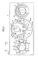
- Fig. 2 shows is a front view of the heater operation unit 10 as viewed from the front side thereof.
- the front side (the side facing the rear of the vehicle) of the heater operation unit 10 is indicated by an arrow FR
- a left-hand side of the heater operation unit (a left-hand side of the vehicle) is indicated by an arrow LH
- an upper side of the heater operation unit 10 an upper side of the vehicle) is indicated by an arrow UP.
- the heater operation unit 10 is provided on an instrument panel (whose illustration is omitted) of the vehicle, and the front side of the heater operation unit 10 is oriented towards the rear of the vehicle and is exposed to an inside of a passenger compartment of the vehicle.
- the heater operation unit 10 makes up part of an air conditioning system 12 (a heater) of the vehicle, and the air conditioning system 12 is made to condition air inside the passenger compartment of the vehicle.
- a substantially plate-shaped cluster panel 14 is provided on the heater operation unit 10 as a front-side member, and the cluster panel 14 makes up part of the instrument panel.
- a circular central hole 16 is formed in a horizontal center of the cluster panel 14 in such a manner as to penetrate the same panel.
- a right-hand side hole 18 and a left-hand side hole 20, which are both circular in shape, are formed in a right-hand side portion and a left-hand side portion of the cluster panel 14, respectively, in such a manner as to penetrate the same panel.
- a circularly tubular container-like central body 22 (a main body) is provided within the central hole 16.
- the central body 22 is made up as a rear-side member by combining a front-side substantially bottomed circularly tubular front body 24 with a rear-side substantially bottomed circularly tubular rear body 26, and a circumferential wall of the rear body 26 is fitted in the inside of a circumferential wall of the front body 24.
- a central operation part 28 is provided on a front side of the central body 22 (the front body 24).
- a blower dial 30 (a rotary knob) is rotatably supported as an operation member at an upper portion on the front side of the central body 22 (the front body 24), and by the blower dial 30 being operated to rotate, the blowing of air into the passenger compartment by the air conditioning system 12 is switched on/off, and the volume of air sent into the passenger compartment by the air conditioning system 12 is controlled.
- a light guiding path 32 as an illuminating portion is provided within the blower dial 30, and the light guiding path 32 is made to transmit light therethrough.
- a front surface of the light guiding path 32 is exposed to the passenger compartment, and the light guiding path 32 is made to communicate with the inside of the central body 22 on a rear side thereof.
- An F/R lever 34 (a fresh outside air/recirculated air knob) is supported as an operation member at a lower portion on the front side of the central body 22 (the front body 24) in such a manner as to rotate about an upper portion thereof, and by the F/R lever being operated to rotate, the mode of the air conditioning system 12 in which air is sent into the passenger compartment is switched (between a mode of introducing fresh outside air to send it into the passenger compartment and a mode of circulating air inside the passenger compartment to recirculate it inside the passenger compartment).
- a light guiding path 32 which is the same as the aforesaid light guiding path 32, is provided inside the F/R lever 34, and a front surface of the light guiding path 32 is exposed to the passenger compartment, while the light guiding path 32 is made to communicate with the interior of the central body 22 on a rear side thereof.
- a flat plate shaped central indicator panel 36 is provided as a display member at an upper portion on the front side of the central body 22 (the front body 24), and a front surface of the central display panel 36 is exposed to the passenger compartment.
- Air current volume indications 38 indicating volumes of air to be sent into the passenger compartment by the air conditioning system 12 and an air current creating symbol are provided at an upper end portion of the central indicator panel 36 which confronts the front surface of the light guiding path 32 of the blower dial 30, and the central indicator panel 36 has a light transmission property at the portion where the air current volume indications 38 are provided and is made to communicate with the interior of the central body 22 on a rear side of the same portion.
- Mode indications 40 indicating the modes of the air conditioning system 12 in which air is sent into the passenger compartment by the air conditioning system 12 are provided at a lower end portion of the central indicator panel 36 which confronts the front surface of the light guiding path 32 of the F/R lever 34, and the central indicator panel 36 has a light transmission property at the portion where the mode indications 40 are provided and is made to communicate with the interior of the central body 22 on a rear side of the same portion.
- An A/X switch 42 (an A/C knob) is supported at a left end portion on the front side of the central body 22 (the front body 24) in such a manner as to be depressed, and by the A/C switch 42 being operated to be depressed, the air conditioning system 12 is switched on or off in such a manner that the air conditioning system switches on an air temperature controlling function to send air whose temperature is controlled into the passenger compartment or the air conditioning system switches off the air temperature controlling function to send air whose temperature is not controlled into the passenger compartment.
- a light guiding path 32 which is the same as the aforesaid light guiding path 32, is provided inside the A/C switch 42, and a front surface of the light guiding path 32 is exposed to the passenger compartment and is made to communicate with the interior of the central body 22 on a rear side thereof.
- an electric circuit 46 is provided on a bottom wall of the rear body 26, and the electric circuit 46 is made as an insert molded part (an insulator) in the rear body 26 and is electrically connected to the blower dial 30, the A/C switch 42 and a rear defogger switch 44.
- a wiring harness (whose illustration is omitted) is electrically connected to the electric circuit 46, and the wiring harness is electrically connected to a operation part (whose illustration is omitted) of the air conditioning system 12.
- An F/R cable 48 is provided as a connecting mechanism on a rear side of the central body 22 (the rear body 26), and the F/R cable 48 is connected to the F/R lever 34 via the bottom wall of the rear body 26 and is also connected to the operation part of the air conditioning system 12.
- the F/R cable 48 is made to operate by the F/R lever 34 being operated to rotate, and the bottom wall of the rear body 26 permits the operation of the F/R cable 48 by the F/R lever 34 being operated to rotate.
- Lamps 50 are provided as electrical functioning portions (illuminating means) at a right-hand side portion and a left-hand side portion on the rear side of the central body 22 (the rear body 26), and the lamps 50 are inserted into the interior of the central body 22 and are electrically connected to the electric circuit 46.
- the lamps 50 are made to illuminate the interior of the central body 22, and the air current volume indications 38 and the mode indications 40 of the central indicator panel 36 and the light guiding paths 32 of the blower dial 30, the F/R lever 34, the A/C switch 42 and the rear defogger switch 44 are made to be illuminated by light from the lamps 50.
- pillar like projections 52 each having a T-shaped cross section and making up an attaching means are provided integrally at each of a right-hand side portion and a left-hand side portion on a circumferential surface of the central body 22 (the front body 24), and eight projections 52 in total are disposed circumferentially at equal intervals on the central body 22.
- Three rectangular communication holes 54 each making up a communication means are formed in each of a right-hand side portion and a left-hand side portion of a circumferential wall of the central body 22 (the front body 24 and the rear body 26) in such a manner as to penetrate the circumferential wall, and the projections 52 are disposed on both sides of the communication hole 54 in the circumferential direction of the central body 22.
- a substantially bottomed circularly tubular right body 56 (a sub-body) is attached to the right-hand side portion of the circumferential wall of the central body 22 as a rear-reside member
- a substantially bottomed circularly tubular left body 58 (a sub-body) is attached to the left-hand side portion of the circumferential wall of the central body 22.
- Proximal end portions of a pair of curved plate-shaped attaching legs 60 which make up an attaching means are provided integrally on each of a circumferential wall of the right body 56 at a portion lying to face the central body 22 (at a right-hand side portion) and a circumferential wall of the left body 58 at a portion lying to face the central body 22 (at a left-hand side portion), and in each pair, the attaching legs 60 extend upwards and downwards.
- a plate-shaped engagement portion 62 having a U-shaped cross section is provided at a proximal end portion and a distal end portion of the attaching leg 60, and by the respective engagement portions 62 of the pair of attaching legs 60 of the right body 56 being brought into engagement with the respective projections 52 on the right-hand side portion of the central body 22, the right body 56 is attached to the right of (just beside) the central body 22, while by the respective engagement portions 62 of the pair of attaching legs 60 of the left body 58 being brought into engagement with the respective projections 52 on the left-hand side portion of the central body 22, the left body 58 is attached to the left of (just beside) the central body 22.
- the right body 56 is made to be attached to a portion of the central body 22 which lies obliquely upwards to the right or obliquely downwards to the right
- the projections 52 on the central body 22 being changed with which the respective engagement portions 62 of the pair of attaching legs 60 of the left body 58 are brought into engagement
- the left body 58 is made to be attached to a portion of the central body 22 which lies obliquely upwards to the left or obliquely downwards to the left.
- a substantially rectangular through hole 64 making up a communication means is formed between the pair of attaching legs 60 on each of the circumferential wall of the right body 56 and the circumferential wall of the left body 58 in such a manner as to penetrate the circumferential wall, and an interior of the right body 56 and an interior of the left body 58 are each made to communicate with the interior of the central body 22 via the through hole 64 and the communication hole 54, whereby the lamps 50 are allowed to illuminate the interior of the right body 56 and the interior of the left body 58 via the interior of the central body 22, the communication holes 54 and the through holes 64.
- the right body 56 and the left body 58 cover rear sides of the right-hand side hole 18 portion and the left-hand side hole 20 portion of the cluster panel 14, respectively.
- An A/M dial 66 (a rotary knob) is rotatably supported as an operation member with in the right-hand side hole 18 in the cluster panel 14, and by the A/M dial 66 being operated to rotate, the temperature of air is controlled which is sent into the passenger compartment when the air conditioning system 12 switches on the air conditioning function.
- a light guiding path 32 which is the same as the one described above, is provided in the A/M dial 66, and a front surface of the light guiding path 32 is exposed to the passenger compartment, while a rear side of the light guiding path 32 is made to communicate with the interior of the right body 56.
- An annular disc-shaped temperature indication panel 68 is provided as an indication member on the front side of the cluster panel 14 in such a manner as to surround a circumference of the A/M dial 66, and a front surface of the temperature indication panel 68 is exposed to the passenger compartment.
- Temperature indications 70 which indicate temperatures of air that is sent into the passenger compartment by the air conditioning system 12 are provided on the temperature indication panel 68 in such a manner as to be associated with the front surface of the light guiding path 32 of the A/M dial 66.
- the temperature indication panel 68 has a light transmission property at the portion where the temperature indications 70 are provided and is made to communicate with the interior of the right body 56 on a rear side thereof.
- An A/M cable 72 is provided as a connecting mechanism on a rear side of the right body 56, and the A/M cable 72 is connected to the A/M dial 66 via a bottom wall of the right body 56.
- the A/M cable 72 is made to operate by the A/M dial 66 being operated to rotate, and the A/M cable 72 is connected to the operation part of the air conditioning system 12.
- a mode dial 74 (a rotary knob) is supported rotatably as an operation member within the right-hand side hole 20 in the cluster panel 14, and by the mode dial 74 being operated to rotate, the mode of the air conditioning system 12 in which air is sent into the passenger compartment is switched (between a mode in which air is sent to an upper body of an occupant, a mode in which air is sent to the upper body and feet of the occupant, a mode in which air is sent to the feet of the occupant and a passenger compartment side surface of a windshield of the vehicle, and a mode in which air is sent to the passenger compartment side surface of the windshield of the vehicle).
- a light guiding path 32 which is the same as the one described above, is provided within the mode dial 74, and a front surface of the light guiding path 32 is exposed to the passenger compartment, while a rear side of the light guiding path 32 is made to communicate with the interior of the left body 58.
- An annular disc-shaped mode indication panel 76 is provided as an indication member on the front side of the cluster panel 14 in such a manner as to surround a circumference of the mode dial 74, and a front surface of the mode indication panel 76 is exposed to the passenger compartment.
- Mode indications 78 which indicate modes of air that is sent into the passenger compartment by the air conditioning system 12 are provided on the mode indication panel 76 in such a manner as to be associated with the front surface of the light guiding path 32 of the mode dial 74.
- the mode indication panel 76 has a light transmission property at the portion where the mode indications 78 are provided and is made to communicate with the interior of the left body 58 on a rear side thereof.
- a mode cable 80 is provided as a connecting mechanism on a rear side of the left body 58, and the mode cable 80 is connected to the mode dial 74 via a bottom wall of the left body 58.
- the mode cable 80 is made to operate by the mode dial 74 being operated to rotate, and the mode cable 80 is connected to the operation part of the air conditioning system 12.
- the laps 50 are made to illuminate the interior of the right body 56 and the interior of the left body 58 via the interior of the central body 22, the communication holes 54 and the through holes 64, whereby the temperature indications 70 of the temperature indication panel 68 and the mode indications 78 of the mode indication panel 76 and the light guiding paths 32 of the A/M dial 66 and the mode dial 74 are made to be illuminated by light from the lamps 50.
- the A/M dial 66 is disposed to the right of (just beside) of the central operation part 28 (the blower dial 30, the F/R lever 34, the A/C switch 42 and the rear defogger switch 44), while the mode dial 74 is disposed to the left of (just beside) the central operation part 28.
- the central body 22 is provided on a rear side of the central operation part 28, and the right body 56 is provided on a rear side of the A/M dial 66, the left body 58 being provided on a rear side of the mode dial 74. Then, the right body 56 is attached to a right-hand side of (just beside) the central operation part 28 and the left body 58 is attached to a left-hand side of (just beside) the central operation part 28.
- the right body 56 is made to be attached to the portion of the central body 22 which lies obliquely upwards to the right or obliquely downwards to the right
- the left body 58 is made to be attached to the portion of the central body 22 which lies obliquely upwards to the left or obliquely downwards to the left.
- the A/M dial 66 can easily be disposed at the portion which lies obliquely upwards to the right or obliquely downwards to the right of the central operation part 28, and the mode dial 74 can easily be disposed at the portion which lies obliquely upwards to the left or obliquely downwards to the left of the central operation part 28.
- This can facilitate a change in design of the heater operation unit 10, thereby making it possible to increase the degree of freedom in design of the heater operation unit 10.
- blower dial 30, the A/C switch 42 and the rear defogger switch 44 which need to be electrically connected to the electric circuit 46, are all provided on the front side of the central body 22 where the electric circuit 46 is provided.
- the interior of the right body 56 is made to communicate with the interior of the central body 22 via the through hole 64 in the light body 56 and the communication hole 54 in the central body 22, while the interior of the left body 58 is made to communicate with the interior of the central body 22 via the through hole 64 in the left body 58 and the communication hole 54 in the central body 22, whereby the lamps 50 provided on the central body 22 are allowed to illuminate not only the central operation part 28 (including the central indication panel 36) but also the A/M dial 66 (including the temperature indication panel 68) and the mode dial 74 (including the mode indication panel 76).
- the F/R lever 34 is configured as a lever which can be operated to move (slide) in a circle
- the F/R lever 34 may be changed to adopt a configuration in which the F/R lever 34 is made as a dial which is operated to rotate or a switch which is operated to be depressed.
- the configuration is adopted in which the A/M dial 66 and the mode dial 70 are made as the dials which can be operated to rotate
- a configuration may be adopted in which the A/M dial 66 and the mode dial 74 are each made as a lever which can be operated to move or slide in a circle.
- a configuration as shown in Fig. 4 may be adopted in which six projections 52 are provided at each of the right-hand side portion and the left-hand side portion of the circumferential surface of the central body 22.
- the six projections 52 are disposed at equal intervals in the circumferential direction of the central body at each of the right-hand side portion and the left-hand side portion of the circumferential surface of the central body. Furthermore, communication holes 54 are formed in the circumferential wall of the central body 22 at each of the right-hand side portion and the left-hand side portion between second and third, third and fourth and fourth and fifth projections 52 from the top.
- the right body 56 can be attached to the portion lying obliquely upwards to the right of the central body 22, and at the same time, the left body 58 can be attached to the portion lying obliquely downwards to the left of the central body 22, while the right body 56 can be attached to the portion lying obliquely downwards to the right of the central body 22, and at the same time, the left body 58 can be attached to the portion lying obliquely upwards to the left of the central body 22.
- the A/M dial 66 can be disposed at the portion lying obliquely upwards to the right of the central operation part 28, and at the same time, the mode dial 74 can be disposed at the portion lying obliquely downwards to the left of the central operation part 28, while the A/M dial 66 can be disposed at the portion lying obliquely downwards to the right of the central operation part 28, and at the same time, the mode dial 74 can be disposed at the portion lying obliquely upwards to the left of the central operation part 28.
- the configuration is adopted in which the electric circuit 46 is made into the insert molded part (the insulator) in the central body 22 (the bottom wall of the rear body 26)
- a configuration may be adopted in which a printed circuit board to which the electric circuit 46 is provided is attached to the central body 22 (the bottom wall of the rear body 26).
Landscapes
- Physics & Mathematics (AREA)
- Thermal Sciences (AREA)
- Engineering & Computer Science (AREA)
- Mechanical Engineering (AREA)
- Air-Conditioning For Vehicles (AREA)
- Mechanical Control Devices (AREA)
Abstract
Description
- The present invention relates to an operation unit for controlling an air conditioning system by operation members being operated.
- As an operation unit, there is an operation unit in which a plurality of operation members such as an air amount adjustment knob, a temperature control knob and key tops are on an operation panel (for example, refer to Japanese Patent No.
3317848 - In this operation unit, rear sides of the plurality of operation members are covered by a case, and a printed circuit board is attached to a rear side of the case. Lamps and light emitting diodes are provided on the printed circuit board, and the lamps and light emitting diodes are inserted into an interior of the case for illuminating the plurality of operation members.
- In this operation unit, however, the rear sides of the plurality of operation members are covered by only the single case. Because of this, when the design of the operation unit is changed by changing the arrangement of the plurality of operation members on the operation panel, the case cannot cover the rear sides of the plurality of operation members so changed in their arrangement, whereby there is caused a problem that the design of the operation unit is difficult to be changed and hence, the degree of freedom in changing the design of the operation unit is reduced.
- Here, when the case is divided into a plurality of cases, even in the event that the arrangement of the plurality of operation members on the operation panel is changed so as to change the design of the operation unit, the rear sides of the plurality of operation members can be covered by the plurality of cases. Because of this, the degree of freedom in design of the operation unit can be increased.
- In this case, however, in the event that a printed circuit board is provided for each case, the necessity is caused of providing a lamp or a light emitting diode for each printed circuit board and this then causes the necessity of connecting a wiring harness to each printed circuit board, leading to a problem that the production costs are increased.
- The invention has been made in view of the situations and an object thereof is to provide an operation unit which can reduce the production costs.
- According to a first aspect of the invention, there is provided an operation unit comprising:
- a plurality of operation members provided in an air conditioning system for conditioning air inside a passenger compartment of a vehicle in such a manner as to be operated to control the air conditioning system;
- a first rear-side member provided on a rear side of one of the plurality of operation members;
- at least one second rear-side member provided on a rear side of the operation members on which the first rear-side member is not provided; and
- an electrical functioning portion which is provided on the first rear-side member and has electrical functions for the operation member on which the rear-side member is provided and the operation members on which the second rear-side member is provided.
- According to a second aspect of the invention, there is provided an operation unit as set forth in the first aspect of the invention, wherein the electrical functioning portions illuminate the operation member on which the first rear-side member is provided and the operation member on the second rear-side member is provided.
- In the operation unit set forth in the first aspect of the invention, the plurality of operation members are provided in the air conditioning system for conditioning air inside the passenger compartment of the vehicle, and the air conditioning system is controlled by the operation members being operated. In addition, the first and second rear-side members are provided on the rear sides of the plurality of operation members.
- Here, the electrical functioning portion provided on the rear-side member has not only the electrical function for the operation member on which the first rear-side member having the electrical functioning portion is provided but also the electrical function for the operation member on which the second rear-side member is provided. Because of this, the necessity of providing an electrical functioning portion for each rear-side member can be obviated, thereby making it possible to reduce the production costs.
- In the operation unit set forth in the second aspect of the invention, the electrical functioning portion has not only the electrical function for the operation member on which the first rear-side member having the electrical functioning portion is provided but also the electrical function for the operation member on which the second rear-side members having no electrical functioning portion is provided. Because of this, the production costs can effectively be reduced.
-
-
Fig. 1 is an exploded perspective view showing a heater operation unit according to an embodiment of the invention as viewed obliquely from the right of a front side thereof. -
Fig. 2 is a front view showing the heater operation unit according to the embodiment of the invention as viewed from the front side thereof. -
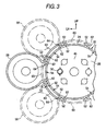
Fig. 3 is a sectional view showing a central body and a left body of the heater operation unit according to the embodiment of the invention as viewed from the front side of the heater operation unit. -
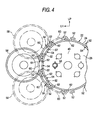
Fig. 4 is a sectional view showing another example of a central body and a left body of the heater operation unit according to the embodiment of the invention as viewed from the front side of the heater unit. -
Fig. 1 is an exploded perspective view of a heater operation unit 10- according to an embodiment which is configured by applying an operation unit of the invention thereto which shows theoperation unit 10 as viewed obliquely from the right of a front side thereof, andFig. 2 shows is a front view of theheater operation unit 10 as viewed from the front side thereof. Note that in the drawings, the front side (the side facing the rear of the vehicle) of theheater operation unit 10 is indicated by an arrow FR, a left-hand side of the heater operation unit (a left-hand side of the vehicle) is indicated by an arrow LH, and an upper side of the heater operation unit 10 (an upper side of the vehicle) is indicated by an arrow UP. - The
heater operation unit 10 according to the embodiment is provided on an instrument panel (whose illustration is omitted) of the vehicle, and the front side of theheater operation unit 10 is oriented towards the rear of the vehicle and is exposed to an inside of a passenger compartment of the vehicle. Theheater operation unit 10 makes up part of an air conditioning system 12 (a heater) of the vehicle, and theair conditioning system 12 is made to condition air inside the passenger compartment of the vehicle. - A substantially plate-
shaped cluster panel 14 is provided on theheater operation unit 10 as a front-side member, and thecluster panel 14 makes up part of the instrument panel. A circularcentral hole 16 is formed in a horizontal center of thecluster panel 14 in such a manner as to penetrate the same panel. In addition, a right-hand side hole 18 and a left-hand side hole 20, which are both circular in shape, are formed in a right-hand side portion and a left-hand side portion of thecluster panel 14, respectively, in such a manner as to penetrate the same panel. - A circularly tubular container-like central body 22 (a main body) is provided within the
central hole 16. Thecentral body 22 is made up as a rear-side member by combining a front-side substantially bottomed circularly tubularfront body 24 with a rear-side substantially bottomed circularly tubularrear body 26, and a circumferential wall of therear body 26 is fitted in the inside of a circumferential wall of thefront body 24. - A
central operation part 28 is provided on a front side of the central body 22 (the front body 24). - A blower dial 30 (a rotary knob) is rotatably supported as an operation member at an upper portion on the front side of the central body 22 (the front body 24), and by the
blower dial 30 being operated to rotate, the blowing of air into the passenger compartment by theair conditioning system 12 is switched on/off, and the volume of air sent into the passenger compartment by theair conditioning system 12 is controlled. A light guidingpath 32 as an illuminating portion is provided within theblower dial 30, and thelight guiding path 32 is made to transmit light therethrough. A front surface of thelight guiding path 32 is exposed to the passenger compartment, and thelight guiding path 32 is made to communicate with the inside of thecentral body 22 on a rear side thereof. - An F/R lever 34 (a fresh outside air/recirculated air knob) is supported as an operation member at a lower portion on the front side of the central body 22 (the front body 24) in such a manner as to rotate about an upper portion thereof, and by the F/R lever being operated to rotate, the mode of the
air conditioning system 12 in which air is sent into the passenger compartment is switched (between a mode of introducing fresh outside air to send it into the passenger compartment and a mode of circulating air inside the passenger compartment to recirculate it inside the passenger compartment). A light guidingpath 32, which is the same as the aforesaidlight guiding path 32, is provided inside the F/R lever 34, and a front surface of thelight guiding path 32 is exposed to the passenger compartment, while thelight guiding path 32 is made to communicate with the interior of thecentral body 22 on a rear side thereof. - A flat plate shaped
central indicator panel 36 is provided as a display member at an upper portion on the front side of the central body 22 (the front body 24), and a front surface of thecentral display panel 36 is exposed to the passenger compartment. - Air
current volume indications 38 indicating volumes of air to be sent into the passenger compartment by theair conditioning system 12 and an air current creating symbol are provided at an upper end portion of thecentral indicator panel 36 which confronts the front surface of thelight guiding path 32 of theblower dial 30, and thecentral indicator panel 36 has a light transmission property at the portion where the aircurrent volume indications 38 are provided and is made to communicate with the interior of thecentral body 22 on a rear side of the same portion. -
Mode indications 40 indicating the modes of theair conditioning system 12 in which air is sent into the passenger compartment by theair conditioning system 12 are provided at a lower end portion of thecentral indicator panel 36 which confronts the front surface of thelight guiding path 32 of the F/R lever 34, and thecentral indicator panel 36 has a light transmission property at the portion where themode indications 40 are provided and is made to communicate with the interior of thecentral body 22 on a rear side of the same portion. - An A/X switch 42 (an A/C knob) is supported at a left end portion on the front side of the central body 22 (the front body 24) in such a manner as to be depressed, and by the A/
C switch 42 being operated to be depressed, theair conditioning system 12 is switched on or off in such a manner that the air conditioning system switches on an air temperature controlling function to send air whose temperature is controlled into the passenger compartment or the air conditioning system switches off the air temperature controlling function to send air whose temperature is not controlled into the passenger compartment. A light guidingpath 32, which is the same as the aforesaidlight guiding path 32, is provided inside the A/C switch 42, and a front surface of thelight guiding path 32 is exposed to the passenger compartment and is made to communicate with the interior of thecentral body 22 on a rear side thereof. - Inside the
central body 22, anelectric circuit 46 is provided on a bottom wall of therear body 26, and theelectric circuit 46 is made as an insert molded part (an insulator) in therear body 26 and is electrically connected to theblower dial 30, the A/C switch 42 and arear defogger switch 44. A wiring harness (whose illustration is omitted) is electrically connected to theelectric circuit 46, and the wiring harness is electrically connected to a operation part (whose illustration is omitted) of theair conditioning system 12. - An F/
R cable 48 is provided as a connecting mechanism on a rear side of the central body 22 (the rear body 26), and the F/R cable 48 is connected to the F/R lever 34 via the bottom wall of therear body 26 and is also connected to the operation part of theair conditioning system 12. The F/R cable 48 is made to operate by the F/R lever 34 being operated to rotate, and the bottom wall of therear body 26 permits the operation of the F/R cable 48 by the F/R lever 34 being operated to rotate. -
Lamps 50 are provided as electrical functioning portions (illuminating means) at a right-hand side portion and a left-hand side portion on the rear side of the central body 22 (the rear body 26), and thelamps 50 are inserted into the interior of thecentral body 22 and are electrically connected to theelectric circuit 46. Thelamps 50 are made to illuminate the interior of thecentral body 22, and the aircurrent volume indications 38 and themode indications 40 of thecentral indicator panel 36 and thelight guiding paths 32 of theblower dial 30, the F/R lever 34, the A/C switch 42 and therear defogger switch 44 are made to be illuminated by light from thelamps 50. - Four pillar like
projections 52 each having a T-shaped cross section and making up an attaching means are provided integrally at each of a right-hand side portion and a left-hand side portion on a circumferential surface of the central body 22 (the front body 24), and eightprojections 52 in total are disposed circumferentially at equal intervals on thecentral body 22. - Three
rectangular communication holes 54 each making up a communication means are formed in each of a right-hand side portion and a left-hand side portion of a circumferential wall of the central body 22 (thefront body 24 and the rear body 26) in such a manner as to penetrate the circumferential wall, and theprojections 52 are disposed on both sides of thecommunication hole 54 in the circumferential direction of thecentral body 22. - As is shown in detail in
Fig. 3 , a substantially bottomed circularly tubular right body 56 (a sub-body) is attached to the right-hand side portion of the circumferential wall of thecentral body 22 as a rear-reside member, and a substantially bottomed circularly tubular left body 58 (a sub-body) is attached to the left-hand side portion of the circumferential wall of thecentral body 22. Proximal end portions of a pair of curved plate-shaped attachinglegs 60 which make up an attaching means are provided integrally on each of a circumferential wall of theright body 56 at a portion lying to face the central body 22 (at a right-hand side portion) and a circumferential wall of theleft body 58 at a portion lying to face the central body 22 (at a left-hand side portion), and in each pair, the attachinglegs 60 extend upwards and downwards. - A plate-
shaped engagement portion 62 having a U-shaped cross section is provided at a proximal end portion and a distal end portion of the attachingleg 60, and by therespective engagement portions 62 of the pair of attachinglegs 60 of theright body 56 being brought into engagement with therespective projections 52 on the right-hand side portion of thecentral body 22, theright body 56 is attached to the right of (just beside) thecentral body 22, while by therespective engagement portions 62 of the pair of attachinglegs 60 of theleft body 58 being brought into engagement with therespective projections 52 on the left-hand side portion of thecentral body 22, theleft body 58 is attached to the left of (just beside) thecentral body 22. In addition, by theprojections 52 on thecentral body 22 being changed with which therespective engagement portions 62 of the pair of attachinglegs 60 of theright body 56 are brought into engagement, theright body 56 is made to be attached to a portion of thecentral body 22 which lies obliquely upwards to the right or obliquely downwards to the right, while by theprojections 52 on thecentral body 22 being changed with which therespective engagement portions 62 of the pair of attachinglegs 60 of theleft body 58 are brought into engagement, theleft body 58 is made to be attached to a portion of thecentral body 22 which lies obliquely upwards to the left or obliquely downwards to the left. - A substantially rectangular through
hole 64 making up a communication means is formed between the pair of attachinglegs 60 on each of the circumferential wall of theright body 56 and the circumferential wall of theleft body 58 in such a manner as to penetrate the circumferential wall, and an interior of theright body 56 and an interior of theleft body 58 are each made to communicate with the interior of thecentral body 22 via the throughhole 64 and thecommunication hole 54, whereby thelamps 50 are allowed to illuminate the interior of theright body 56 and the interior of theleft body 58 via the interior of thecentral body 22, thecommunication holes 54 and the throughholes 64. - The
right body 56 and theleft body 58 cover rear sides of the right-hand side hole 18 portion and the left-hand side hole 20 portion of thecluster panel 14, respectively. - An A/M dial 66 (a rotary knob) is rotatably supported as an operation member with in the right-
hand side hole 18 in thecluster panel 14, and by the A/M dial 66 being operated to rotate, the temperature of air is controlled which is sent into the passenger compartment when theair conditioning system 12 switches on the air conditioning function. Alight guiding path 32, which is the same as the one described above, is provided in the A/M dial 66, and a front surface of thelight guiding path 32 is exposed to the passenger compartment, while a rear side of thelight guiding path 32 is made to communicate with the interior of theright body 56. - An annular disc-shaped
temperature indication panel 68 is provided as an indication member on the front side of thecluster panel 14 in such a manner as to surround a circumference of the A/M dial 66, and a front surface of thetemperature indication panel 68 is exposed to the passenger compartment.Temperature indications 70 which indicate temperatures of air that is sent into the passenger compartment by theair conditioning system 12 are provided on thetemperature indication panel 68 in such a manner as to be associated with the front surface of thelight guiding path 32 of the A/M dial 66. Thetemperature indication panel 68 has a light transmission property at the portion where thetemperature indications 70 are provided and is made to communicate with the interior of theright body 56 on a rear side thereof. - - An A/
M cable 72 is provided as a connecting mechanism on a rear side of theright body 56, and the A/M cable 72 is connected to the A/M dial 66 via a bottom wall of theright body 56. The A/M cable 72 is made to operate by the A/M dial 66 being operated to rotate, and the A/M cable 72 is connected to the operation part of theair conditioning system 12. - A mode dial 74 (a rotary knob) is supported rotatably as an operation member within the right-
hand side hole 20 in thecluster panel 14, and by themode dial 74 being operated to rotate, the mode of theair conditioning system 12 in which air is sent into the passenger compartment is switched (between a mode in which air is sent to an upper body of an occupant, a mode in which air is sent to the upper body and feet of the occupant, a mode in which air is sent to the feet of the occupant and a passenger compartment side surface of a windshield of the vehicle, and a mode in which air is sent to the passenger compartment side surface of the windshield of the vehicle). Alight guiding path 32, which is the same as the one described above, is provided within themode dial 74, and a front surface of thelight guiding path 32 is exposed to the passenger compartment, while a rear side of thelight guiding path 32 is made to communicate with the interior of theleft body 58. - An annular disc-shaped
mode indication panel 76 is provided as an indication member on the front side of thecluster panel 14 in such a manner as to surround a circumference of themode dial 74, and a front surface of themode indication panel 76 is exposed to the passenger compartment.Mode indications 78 which indicate modes of air that is sent into the passenger compartment by theair conditioning system 12 are provided on themode indication panel 76 in such a manner as to be associated with the front surface of thelight guiding path 32 of themode dial 74. Themode indication panel 76 has a light transmission property at the portion where themode indications 78 are provided and is made to communicate with the interior of theleft body 58 on a rear side thereof. - A
mode cable 80 is provided as a connecting mechanism on a rear side of theleft body 58, and themode cable 80 is connected to themode dial 74 via a bottom wall of theleft body 58. Themode cable 80 is made to operate by themode dial 74 being operated to rotate, and themode cable 80 is connected to the operation part of theair conditioning system 12. - As has been described heretofore, the
laps 50 are made to illuminate the interior of theright body 56 and the interior of theleft body 58 via the interior of thecentral body 22, the communication holes 54 and the throughholes 64, whereby thetemperature indications 70 of thetemperature indication panel 68 and themode indications 78 of themode indication panel 76 and thelight guiding paths 32 of the A/M dial 66 and themode dial 74 are made to be illuminated by light from thelamps 50. - Next, the function of the embodiment will be described.
- In the
heater operation unit 10 that is configured as has been described heretofore, in thecluster panel 14, the A/M dial 66 is disposed to the right of (just beside) of the central operation part 28 (theblower dial 30, the F/R lever 34, the A/C switch 42 and the rear defogger switch 44), while themode dial 74 is disposed to the left of (just beside) thecentral operation part 28. Furthermore, thecentral body 22 is provided on a rear side of thecentral operation part 28, and theright body 56 is provided on a rear side of the A/M dial 66, theleft body 58 being provided on a rear side of themode dial 74. Then, theright body 56 is attached to a right-hand side of (just beside) thecentral operation part 28 and theleft body 58 is attached to a left-hand side of (just beside) thecentral operation part 28. - Here, the
right body 56 is made to be attached to the portion of thecentral body 22 which lies obliquely upwards to the right or obliquely downwards to the right, while theleft body 58 is made to be attached to the portion of thecentral body 22 which lies obliquely upwards to the left or obliquely downwards to the left. Because of this, in the event that thecluster panel 14 is modified (in particular, the external shape of thecluster panel 14 and the positions of the right-hand side hole 18 and the left-hand side hole 20 are changed), the A/M dial 66 can easily be disposed at the portion which lies obliquely upwards to the right or obliquely downwards to the right of thecentral operation part 28, and themode dial 74 can easily be disposed at the portion which lies obliquely upwards to the left or obliquely downwards to the left of thecentral operation part 28. This can facilitate a change in design of theheater operation unit 10, thereby making it possible to increase the degree of freedom in design of theheater operation unit 10. - Furthermore, the
blower dial 30, the A/C switch 42 and therear defogger switch 44, which need to be electrically connected to theelectric circuit 46, are all provided on the front side of thecentral body 22 where theelectric circuit 46 is provided. Moreover, the interior of theright body 56 is made to communicate with the interior of thecentral body 22 via the throughhole 64 in thelight body 56 and thecommunication hole 54 in thecentral body 22, while the interior of theleft body 58 is made to communicate with the interior of thecentral body 22 via the throughhole 64 in theleft body 58 and thecommunication hole 54 in thecentral body 22, whereby thelamps 50 provided on thecentral body 22 are allowed to illuminate not only the central operation part 28 (including the central indication panel 36) but also the A/M dial 66 (including the temperature indication panel 68) and the mode dial 74 (including the mode indication panel 76). Because of this, the necessity of providing anelectric circuit 46 and alamp 50 in each of theright body 56 and theleft body 58 is obviated, and the necessity of laying out a wiring harness in each of theright body 56 and theleft body 58 is obviated, thereby making it possible to reduce effectively the production costs. - Note that while in the embodiment, the F/
R lever 34 is configured as a lever which can be operated to move (slide) in a circle, the F/R lever 34 may be changed to adopt a configuration in which the F/R lever 34 is made as a dial which is operated to rotate or a switch which is operated to be depressed. - Furthermore, while in the embodiment, the configuration is adopted in which the A/
M dial 66 and themode dial 70 are made as the dials which can be operated to rotate, a configuration may be adopted in which the A/M dial 66 and themode dial 74 are each made as a lever which can be operated to move or slide in a circle. - In addition, while in the embodiment, the configuration is adopted in which the four
projections 52 are provided at each of the right-hand side portion and the left-hand side portion of the circumferential surface of thecentral body 22, a configuration as shown inFig. 4 may be adopted in which sixprojections 52 are provided at each of the right-hand side portion and the left-hand side portion of the circumferential surface of thecentral body 22. - As this occurs, the six
projections 52 are disposed at equal intervals in the circumferential direction of the central body at each of the right-hand side portion and the left-hand side portion of the circumferential surface of the central body. Furthermore, communication holes 54 are formed in the circumferential wall of thecentral body 22 at each of the right-hand side portion and the left-hand side portion between second and third, third and fourth and fourth andfifth projections 52 from the top. - By this configuration, the
right body 56 can be attached to the portion lying obliquely upwards to the right of thecentral body 22, and at the same time, theleft body 58 can be attached to the portion lying obliquely downwards to the left of thecentral body 22, while theright body 56 can be attached to the portion lying obliquely downwards to the right of thecentral body 22, and at the same time, theleft body 58 can be attached to the portion lying obliquely upwards to the left of thecentral body 22. Because of this, the A/M dial 66 can be disposed at the portion lying obliquely upwards to the right of thecentral operation part 28, and at the same time, themode dial 74 can be disposed at the portion lying obliquely downwards to the left of thecentral operation part 28, while the A/M dial 66 can be disposed at the portion lying obliquely downwards to the right of thecentral operation part 28, and at the same time, themode dial 74 can be disposed at the portion lying obliquely upwards to the left of thecentral operation part 28. - In addition, while in the embodiment, the configuration is adopted in which the
electric circuit 46 is made into the insert molded part (the insulator) in the central body 22 (the bottom wall of the rear body 26), a configuration may be adopted in which a printed circuit board to which theelectric circuit 46 is provided is attached to the central body 22 (the bottom wall of the rear body 26).
Claims (4)
- An operation unit comprising:a plurality of operation members provided in an air conditioning system for conditioning air inside a passenger compartment of a vehicle in such a manner as to be operated to control the air conditioning system;a first rear-side member provided on a rear side of one of the plurality of operation members;at least one second rear-side member provided on a rear side of the operation members on which the first rear-side member is not provided; andan electrical functioning portion which is provided on the first rear-side member and has electrical functions for the operation member on which the rear-side member is provided and the operation members on which the second rear-side member is provided.
- The operation unit according to claim 1, wherein the electrical functioning portions illuminate the operation members on which the first rear-side member is provided and the operation member on which the second rear-side member is provided.
- The operation unit according to claim 1, wherein the first rear-side member includes a plurality of attaching portions to which the second rear-side member is attachable.
- The operation unit according to claim 3, wherein the first and second rear-side members include through holes, respectively, so that interiors of the first and second rear-side members communicate each other.
Applications Claiming Priority (1)
| Application Number | Priority Date | Filing Date | Title |
|---|---|---|---|
| JP2007278815A JP5209937B2 (en) | 2007-10-26 | 2007-10-26 | Operating device |
Publications (3)
| Publication Number | Publication Date |
|---|---|
| EP2052892A2 true EP2052892A2 (en) | 2009-04-29 |
| EP2052892A3 EP2052892A3 (en) | 2009-07-08 |
| EP2052892B1 EP2052892B1 (en) | 2010-12-15 |
Family
ID=39967998
Family Applications (1)
| Application Number | Title | Priority Date | Filing Date |
|---|---|---|---|
| EP08018581A Not-in-force EP2052892B1 (en) | 2007-10-26 | 2008-10-23 | Operation unit |
Country Status (5)
| Country | Link |
|---|---|
| US (1) | US8020781B2 (en) |
| EP (1) | EP2052892B1 (en) |
| JP (1) | JP5209937B2 (en) |
| CN (1) | CN101417597B (en) |
| DE (1) | DE602008003962D1 (en) |
Cited By (1)
| Publication number | Priority date | Publication date | Assignee | Title |
|---|---|---|---|---|
| EP3168356B1 (en) | 2015-11-16 | 2019-01-09 | Electrolux Appliances Aktiebolag | Household appliance with a rotational user interface element |
Families Citing this family (3)
| Publication number | Priority date | Publication date | Assignee | Title |
|---|---|---|---|---|
| JP5117952B2 (en) * | 2008-07-24 | 2013-01-16 | 株式会社東海理化電機製作所 | Operating device |
| DE102013205884A1 (en) * | 2013-04-03 | 2014-10-09 | Mahle International Gmbh | Modular system of a control unit |
| JP6729849B2 (en) * | 2016-07-22 | 2020-07-29 | 株式会社デンソーテン | Operation unit assembly structure |
Citations (1)
| Publication number | Priority date | Publication date | Assignee | Title |
|---|---|---|---|---|
| JP3317848B2 (en) | 1996-06-14 | 2002-08-26 | アルプス電気株式会社 | Air conditioning control switch for vehicle |
Family Cites Families (12)
| Publication number | Priority date | Publication date | Assignee | Title |
|---|---|---|---|---|
| FR2452156A1 (en) * | 1979-03-19 | 1980-10-17 | Team | DASHBOARD WITH REMOVABLE INSCRIPTIONS |
| DE3535881A1 (en) * | 1985-10-08 | 1987-04-16 | Preh Elektro Feinmechanik | LIGHTING DEVICE FOR A FRONT PANEL |
| JPS6421010U (en) * | 1987-07-30 | 1989-02-02 | ||
| JPH01163697A (en) * | 1987-09-26 | 1989-06-27 | Toyoda Gosei Co Ltd | Air conditioning control box |
| JP3597649B2 (en) * | 1996-10-15 | 2004-12-08 | 株式会社東海理化電機製作所 | Dial operating device |
| JP3576720B2 (en) * | 1996-10-15 | 2004-10-13 | 株式会社東海理化電機製作所 | Dial operating device |
| JP3779472B2 (en) * | 1998-06-05 | 2006-05-31 | アルプス電気株式会社 | Illuminated operation / display device |
| JP3834473B2 (en) * | 2000-11-30 | 2006-10-18 | 株式会社東海理化電機製作所 | Vehicle operation switch unit |
| JP4239433B2 (en) * | 2001-05-31 | 2009-03-18 | 株式会社デンソー | Air conditioner for vehicles |
| JP2004136840A (en) * | 2002-10-21 | 2004-05-13 | Yuhshin Co Ltd | Heater control device |
| JP2005096579A (en) * | 2003-09-24 | 2005-04-14 | Tokai Rika Co Ltd | Operating device for vehicular air-conditioner |
| JP4560767B2 (en) * | 2003-12-25 | 2010-10-13 | 株式会社ユーシン | Illuminated control knob device |
-
2007
- 2007-10-26 JP JP2007278815A patent/JP5209937B2/en not_active Expired - Fee Related
-
2008
- 2008-10-23 EP EP08018581A patent/EP2052892B1/en not_active Not-in-force
- 2008-10-23 DE DE602008003962T patent/DE602008003962D1/en active Active
- 2008-10-24 US US12/257,872 patent/US8020781B2/en not_active Expired - Fee Related
- 2008-10-27 CN CN2008101691020A patent/CN101417597B/en not_active Expired - Fee Related
Patent Citations (1)
| Publication number | Priority date | Publication date | Assignee | Title |
|---|---|---|---|---|
| JP3317848B2 (en) | 1996-06-14 | 2002-08-26 | アルプス電気株式会社 | Air conditioning control switch for vehicle |
Cited By (2)
| Publication number | Priority date | Publication date | Assignee | Title |
|---|---|---|---|---|
| EP3168356B1 (en) | 2015-11-16 | 2019-01-09 | Electrolux Appliances Aktiebolag | Household appliance with a rotational user interface element |
| EP3168356B2 (en) † | 2015-11-16 | 2023-08-16 | Electrolux Appliances Aktiebolag | Household appliance with a rotational user interface element |
Also Published As
| Publication number | Publication date |
|---|---|
| CN101417597A (en) | 2009-04-29 |
| CN101417597B (en) | 2011-08-03 |
| JP2009107381A (en) | 2009-05-21 |
| EP2052892B1 (en) | 2010-12-15 |
| US8020781B2 (en) | 2011-09-20 |
| DE602008003962D1 (en) | 2011-01-27 |
| JP5209937B2 (en) | 2013-06-12 |
| US20090108083A1 (en) | 2009-04-30 |
| EP2052892A3 (en) | 2009-07-08 |
Similar Documents
| Publication | Publication Date | Title |
|---|---|---|
| US5861589A (en) | Vehicle air-conditioning control switch | |
| US6349616B1 (en) | Steering system | |
| CN102792243B (en) | Control device having a rotary switch back-lit by a light guide | |
| US7163455B2 (en) | Operating device for air conditioner for vehicle | |
| JP2006049011A (en) | Temperature control device for vehicles | |
| US8020781B2 (en) | Operation unit | |
| KR20110046445A (en) | A control device for controlling the function of the vehicle control panel and a corresponding control panel | |
| US7394034B2 (en) | Electric push-button switch with lighting arrangement | |
| US7811160B2 (en) | Operating device of vehicle air conditioner | |
| US7084360B2 (en) | Elastomeric vehicle control switch | |
| CN111114427A (en) | Interior lighting device | |
| US20120313653A1 (en) | Switch identification system for vehicle | |
| US20080231615A1 (en) | Input device | |
| US9589746B2 (en) | Switch device for vehicular air conditioning system | |
| US8248265B2 (en) | Vehicle console display buttons and vehicle consoles incorporating the same | |
| JP3559898B2 (en) | Switch device for vehicles | |
| US20160048153A1 (en) | Modular system of an operating device | |
| US6087601A (en) | Modular multi-purpose switch | |
| KR101550732B1 (en) | Controller of air conditioning system for automotive vehicles | |
| US20080087490A1 (en) | Control element for regulating a heating, ventilation, or air conditioning unit of a motor vehicle | |
| JP5056515B2 (en) | Switch system | |
| KR20100005743U (en) | Multi lighting button | |
| US20110303514A1 (en) | Dial operation device for vehicle | |
| US7067752B2 (en) | Seesaw button of heater control unit | |
| CN106114223B (en) | Automobile, automobile instrument and the user interface for controlling automobile equipment |
Legal Events
| Date | Code | Title | Description |
|---|---|---|---|
| PUAI | Public reference made under article 153(3) epc to a published international application that has entered the european phase |
Free format text: ORIGINAL CODE: 0009012 |
|
| AK | Designated contracting states |
Kind code of ref document: A2 Designated state(s): AT BE BG CH CY CZ DE DK EE ES FI FR GB GR HR HU IE IS IT LI LT LU LV MC MT NL NO PL PT RO SE SI SK TR |
|
| AX | Request for extension of the european patent |
Extension state: AL BA MK RS |
|
| PUAL | Search report despatched |
Free format text: ORIGINAL CODE: 0009013 |
|
| AK | Designated contracting states |
Kind code of ref document: A3 Designated state(s): AT BE BG CH CY CZ DE DK EE ES FI FR GB GR HR HU IE IS IT LI LT LU LV MC MT NL NO PL PT RO SE SI SK TR |
|
| AX | Request for extension of the european patent |
Extension state: AL BA MK RS |
|
| 17P | Request for examination filed |
Effective date: 20090902 |
|
| 17Q | First examination report despatched |
Effective date: 20091022 |
|
| AKX | Designation fees paid |
Designated state(s): DE FR GB |
|
| GRAP | Despatch of communication of intention to grant a patent |
Free format text: ORIGINAL CODE: EPIDOSNIGR1 |
|
| GRAS | Grant fee paid |
Free format text: ORIGINAL CODE: EPIDOSNIGR3 |
|
| GRAA | (expected) grant |
Free format text: ORIGINAL CODE: 0009210 |
|
| AK | Designated contracting states |
Kind code of ref document: B1 Designated state(s): DE FR GB |
|
| REG | Reference to a national code |
Ref country code: GB Ref legal event code: FG4D |
|
| REF | Corresponds to: |
Ref document number: 602008003962 Country of ref document: DE Date of ref document: 20110127 Kind code of ref document: P |
|
| PLBE | No opposition filed within time limit |
Free format text: ORIGINAL CODE: 0009261 |
|
| STAA | Information on the status of an ep patent application or granted ep patent |
Free format text: STATUS: NO OPPOSITION FILED WITHIN TIME LIMIT |
|
| 26N | No opposition filed |
Effective date: 20110916 |
|
| REG | Reference to a national code |
Ref country code: DE Ref legal event code: R097 Ref document number: 602008003962 Country of ref document: DE Effective date: 20110916 |
|
| REG | Reference to a national code |
Ref country code: FR Ref legal event code: PLFP Year of fee payment: 9 |
|
| REG | Reference to a national code |
Ref country code: DE Ref legal event code: R084 Ref document number: 602008003962 Country of ref document: DE |
|
| REG | Reference to a national code |
Ref country code: FR Ref legal event code: PLFP Year of fee payment: 10 |
|
| REG | Reference to a national code |
Ref country code: FR Ref legal event code: PLFP Year of fee payment: 11 |
|
| PGFP | Annual fee paid to national office [announced via postgrant information from national office to epo] |
Ref country code: FR Payment date: 20190913 Year of fee payment: 12 |
|
| PGFP | Annual fee paid to national office [announced via postgrant information from national office to epo] |
Ref country code: GB Payment date: 20191025 Year of fee payment: 12 |
|
| GBPC | Gb: european patent ceased through non-payment of renewal fee |
Effective date: 20201023 |
|
| PG25 | Lapsed in a contracting state [announced via postgrant information from national office to epo] |
Ref country code: FR Free format text: LAPSE BECAUSE OF NON-PAYMENT OF DUE FEES Effective date: 20201031 |
|
| PG25 | Lapsed in a contracting state [announced via postgrant information from national office to epo] |
Ref country code: GB Free format text: LAPSE BECAUSE OF NON-PAYMENT OF DUE FEES Effective date: 20201023 |
|
| PGFP | Annual fee paid to national office [announced via postgrant information from national office to epo] |
Ref country code: DE Payment date: 20210914 Year of fee payment: 14 |
|
| REG | Reference to a national code |
Ref country code: DE Ref legal event code: R119 Ref document number: 602008003962 Country of ref document: DE |
|
| PG25 | Lapsed in a contracting state [announced via postgrant information from national office to epo] |
Ref country code: DE Free format text: LAPSE BECAUSE OF NON-PAYMENT OF DUE FEES Effective date: 20230503 |