EP2052814A1 - Method for deciding a bevel curve, method for deciding a locus of a bevel, method for processing a lens and apparatus for processing a lens - Google Patents
Method for deciding a bevel curve, method for deciding a locus of a bevel, method for processing a lens and apparatus for processing a lens Download PDFInfo
- Publication number
- EP2052814A1 EP2052814A1 EP08006394A EP08006394A EP2052814A1 EP 2052814 A1 EP2052814 A1 EP 2052814A1 EP 08006394 A EP08006394 A EP 08006394A EP 08006394 A EP08006394 A EP 08006394A EP 2052814 A1 EP2052814 A1 EP 2052814A1
- Authority
- EP
- European Patent Office
- Prior art keywords
- bevel
- curve
- deciding
- lens
- value
- Prior art date
- Legal status (The legal status is an assumption and is not a legal conclusion. Google has not performed a legal analysis and makes no representation as to the accuracy of the status listed.)
- Granted
Links
- 238000012545 processing Methods 0.000 title claims description 85
- 238000000034 method Methods 0.000 title claims description 46
- 238000012937 correction Methods 0.000 claims abstract description 52
- 230000002093 peripheral effect Effects 0.000 claims abstract description 45
- 230000015572 biosynthetic process Effects 0.000 abstract description 3
- 238000010586 diagram Methods 0.000 description 13
- 238000004364 calculation method Methods 0.000 description 6
- 239000000700 radioactive tracer Substances 0.000 description 6
- 230000001747 exhibiting effect Effects 0.000 description 5
- 239000011521 glass Substances 0.000 description 4
- 239000000463 material Substances 0.000 description 4
- 230000003287 optical effect Effects 0.000 description 4
- 241001422033 Thestylus Species 0.000 description 3
- 238000004891 communication Methods 0.000 description 3
- 238000010276 construction Methods 0.000 description 3
- 230000006870 function Effects 0.000 description 3
- 238000005498 polishing Methods 0.000 description 3
- 238000005259 measurement Methods 0.000 description 2
- 230000003247 decreasing effect Effects 0.000 description 1
- 238000005516 engineering process Methods 0.000 description 1
- 238000012986 modification Methods 0.000 description 1
- 230000004048 modification Effects 0.000 description 1
- 230000001179 pupillary effect Effects 0.000 description 1
- 238000004088 simulation Methods 0.000 description 1
Images



Classifications
-
- B—PERFORMING OPERATIONS; TRANSPORTING
- B24—GRINDING; POLISHING
- B24B—MACHINES, DEVICES, OR PROCESSES FOR GRINDING OR POLISHING; DRESSING OR CONDITIONING OF ABRADING SURFACES; FEEDING OF GRINDING, POLISHING, OR LAPPING AGENTS
- B24B13/00—Machines or devices designed for grinding or polishing optical surfaces on lenses or surfaces of similar shape on other work; Accessories therefor
-
- B—PERFORMING OPERATIONS; TRANSPORTING
- B24—GRINDING; POLISHING
- B24B—MACHINES, DEVICES, OR PROCESSES FOR GRINDING OR POLISHING; DRESSING OR CONDITIONING OF ABRADING SURFACES; FEEDING OF GRINDING, POLISHING, OR LAPPING AGENTS
- B24B1/00—Processes of grinding or polishing; Use of auxiliary equipment in connection with such processes
-
- B—PERFORMING OPERATIONS; TRANSPORTING
- B24—GRINDING; POLISHING
- B24B—MACHINES, DEVICES, OR PROCESSES FOR GRINDING OR POLISHING; DRESSING OR CONDITIONING OF ABRADING SURFACES; FEEDING OF GRINDING, POLISHING, OR LAPPING AGENTS
- B24B19/00—Single-purpose machines or devices for particular grinding operations not covered by any other main group
- B24B19/02—Single-purpose machines or devices for particular grinding operations not covered by any other main group for grinding grooves, e.g. on shafts, in casings, in tubes, homokinetic joint elements
- B24B19/03—Single-purpose machines or devices for particular grinding operations not covered by any other main group for grinding grooves, e.g. on shafts, in casings, in tubes, homokinetic joint elements for grinding grooves in glass workpieces, e.g. decorative grooves
-
- B—PERFORMING OPERATIONS; TRANSPORTING
- B24—GRINDING; POLISHING
- B24B—MACHINES, DEVICES, OR PROCESSES FOR GRINDING OR POLISHING; DRESSING OR CONDITIONING OF ABRADING SURFACES; FEEDING OF GRINDING, POLISHING, OR LAPPING AGENTS
- B24B47/00—Drives or gearings; Equipment therefor
- B24B47/22—Equipment for exact control of the position of the grinding tool or work at the start of the grinding operation
- B24B47/225—Equipment for exact control of the position of the grinding tool or work at the start of the grinding operation for bevelling optical work, e.g. lenses
-
- B—PERFORMING OPERATIONS; TRANSPORTING
- B24—GRINDING; POLISHING
- B24B—MACHINES, DEVICES, OR PROCESSES FOR GRINDING OR POLISHING; DRESSING OR CONDITIONING OF ABRADING SURFACES; FEEDING OF GRINDING, POLISHING, OR LAPPING AGENTS
- B24B9/00—Machines or devices designed for grinding edges or bevels on work or for removing burrs; Accessories therefor
- B24B9/02—Machines or devices designed for grinding edges or bevels on work or for removing burrs; Accessories therefor characterised by a special design with respect to properties of materials specific to articles to be ground
- B24B9/06—Machines or devices designed for grinding edges or bevels on work or for removing burrs; Accessories therefor characterised by a special design with respect to properties of materials specific to articles to be ground of non-metallic inorganic material, e.g. stone, ceramics, porcelain
- B24B9/08—Machines or devices designed for grinding edges or bevels on work or for removing burrs; Accessories therefor characterised by a special design with respect to properties of materials specific to articles to be ground of non-metallic inorganic material, e.g. stone, ceramics, porcelain of glass
- B24B9/14—Machines or devices designed for grinding edges or bevels on work or for removing burrs; Accessories therefor characterised by a special design with respect to properties of materials specific to articles to be ground of non-metallic inorganic material, e.g. stone, ceramics, porcelain of glass of optical work, e.g. lenses, prisms
- B24B9/148—Machines or devices designed for grinding edges or bevels on work or for removing burrs; Accessories therefor characterised by a special design with respect to properties of materials specific to articles to be ground of non-metallic inorganic material, e.g. stone, ceramics, porcelain of glass of optical work, e.g. lenses, prisms electrically, e.g. numerically, controlled
-
- G—PHYSICS
- G05—CONTROLLING; REGULATING
- G05B—CONTROL OR REGULATING SYSTEMS IN GENERAL; FUNCTIONAL ELEMENTS OF SUCH SYSTEMS; MONITORING OR TESTING ARRANGEMENTS FOR SUCH SYSTEMS OR ELEMENTS
- G05B2219/00—Program-control systems
- G05B2219/30—Nc systems
- G05B2219/36—Nc in input of data, input key till input tape
- G05B2219/36221—Entry of chamfer, beveling, rounding of corner shape
-
- G—PHYSICS
- G05—CONTROLLING; REGULATING
- G05B—CONTROL OR REGULATING SYSTEMS IN GENERAL; FUNCTIONAL ELEMENTS OF SUCH SYSTEMS; MONITORING OR TESTING ARRANGEMENTS FOR SUCH SYSTEMS OR ELEMENTS
- G05B2219/00—Program-control systems
- G05B2219/30—Nc systems
- G05B2219/45—Nc applications
- G05B2219/45157—Grind optical lens
Definitions
- the present invention relates to a method for deciding a bevel curve, a method for deciding a locus of a bevel, a method for processing a lens and an apparatus for processing a lens which is used for conducting these methods.
- apparatuses for processing a lens for processing an uncut lens into a shape fitting a shape of a lens frame of a spectacle frame.
- apparatuses for processing a lens As the apparatus for processing a lens, apparatuses having the so-called function of automatic beveled processing have also been provided.
- a regular lens is used as the uncut lens in the processing using this type of the apparatus for processing a lens, after the information necessary for processing the uncut lens including data of the shape of the frame is provided to the apparatus, a locus of a bevel most suitable for the lens is automatically calculated by the apparatus and the bevel is formed along the obtained locus.
- the most suitable bevel is formed with an excellent balance in special lenses such as a high power minus lens, a high power plus lens, an EX lens and a lenticular lens.
- special lenses such as a high power minus lens, a high power plus lens, an EX lens and a lenticular lens.
- the present invention has an object of enabling formation of a suitable bevel in special lenses even by a person not skilled in the art.
- the present invention provides a method for deciding a locus of a bevel in an EX lens which comprises: in a step of deciding a value of a bevel curve, deciding the value of the bevel curve based on a value of a curve of a concave face of the EX lens; in a step of deciding a first reference position, deciding the first reference position on a peripheral edge in a portion having a minimum thickness at a lower side in a vertical direction of the EX lens based on a thickness of the portion having a minimum thickness; in a step of deciding a second reference position, deciding the second reference position on a peripheral edge in a portion having a maximum thickness at an upper side in a vertical direction of the EX lens based on a ratio of a thickness of the portion having a maximum thickness to the thickness of the portion having a minimum thickness and data of a shape of the EX lens to be obtained by the processing; and, in a step of deciding the locus of the bevel,
- the present invention provides a method for deciding a locus of a bevel in an EX lens which comprises: in a step of deciding a value of a bevel curve, deciding the value of the bevel curve based on a value of a curve of a concave face of the EX lens; in a step of deciding an initial reference axis of the bevel curve, deciding the initial reference axis of the bevel curve in a same direction as a direction of a curvature of the concave face of the EX lens; in a step of deciding a reference position of the bevel, deciding the reference position of the bevel on a peripheral edge in a portion having a minimum thickness at a lower side in a vertical direction of the EX lens based on a thickness of the portion having a minimum thickness; in a step of calculating a value of correction for an initial reference axis of the bevel curve, deriving the value of correction for the initial reference axis of the bevel curve based
- the present invention provides a method for deciding a locus of a bevel in a high power minus lens which comprises: in a step of deciding a value of a bevel curve, deciding the value of the bevel curve based on a value of a curve of a convex face of the high power minus lens; in a step of deciding a first reference position, deciding the first reference position on a peripheral edge in a portion having a minimum thickness of the high power minus lens at a side of a nose of a person wearing the high power minus lens based on a thickness of the portion having a minimum thickness; in a step of deciding a second reference position, deciding the second reference position on a peripheral edge in a portion having a maximum thickness of the high power minus lens at a side of an ear of a person wearing the high power minus lens based on a ratio of a thickness of the portion having a maximum thickness to the thickness of the portion having a minimum thickness and data of a shape of
- the present invention provides a method for deciding a locus of a bevel in a high power minus lens which comprises: in a step of deciding a value of a bevel curve, deciding the value of the bevel curve based on a value of a curve of a convex face of the high power minus lens; in a step of deciding an initial reference axis of the bevel curve, deciding the initial reference axis of a bevel curve in a same direction as a direction of a curvature of the convex face of the high power minus lens; in a step of deciding a reference position of the bevel, deciding the reference position of the bevel on a peripheral edge in a portion having a minimum thickness of the high power minus lens at a side of a nose of a person wearing the high power minus lens based on a thickness of the portion having a minimum thickness; in a step of calculating a value of correction for an initial reference axis of the bevel curve, deriv
- the present invention provides a method for deciding a locus of a bevel in a lenticular lens which comprises: in a step of deciding a value of a bevel curve, deciding the value of the bevel curve based on a value of a curve of a concave face of the lenticular lens; in a step of deciding a reference position of the bevel, deciding the reference position of the bevel on a peripheral edge in a portion having a minimum thickness at a side of a nose or a ear of a person wearing the lenticular lens based on a thickness of the portion having a minimum thickness; in a step of deciding a correction for a value of a curve, deciding the correction for a value of a curve based on a ratio of the thickness of the portion having a minimum thickness of the lenticular lens at a side of a nose or an ear to a thickness of a portion having a maximum thickness of the lenticular lens in a vertical
- the present invention provides a method for deciding a locus of a bevel in a high power plus lens which comprises: in a step of deciding a value of a bevel curve, deciding the value of the bevel curve based on a value of a curve of a concave face of the high power plus lens; in a step of deciding a reference position of the bevel, deciding the reference position of the bevel on a peripheral edge in a portion having a minimum thickness of the high power plus lens based on a thickness of the portion having a minimum thickness; in a step of deciding a correction for a value of a curve, deciding the correction for a value of a curve based on a ratio of the value of a curve of the concave face to a value of a curve of a convex face of the high power plus lens or based on the value of a curve of a convex face alone of the high power plus lens; and, in a step of deciding the locus of the be
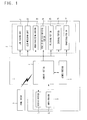
- Fig. 1 shows a block diagram schematically exhibiting the function of the apparatus for processing a lens as an embodiment of the present invention.
- the apparatus for processing a lens 1 comprises a lens-processing portion 2 in which an uncut lens is processed to provide a shape fitting the lens frame of the spectacle frame, an operation panel 3, a control portion 4 and a memory portion 5.
- the lens-processing portion 2 comprises a lens-holding unit 21, a lens-measuring portion 22, a rough processing portion 23, a beveled and flat grinding portion 24, a polishing portion 25, a grooving portion 26 and a chamfering portion 27.
- the lens-holding unit 21 comprises, as shown in Fig. 2 , a pair of lens-holding shafts 211 and 212 extending in the direction of the light axis of an uncut lens L.
- the uncut lens is held between the two lens-holding shafts 211 and 212 at both faces of the uncut lens L.
- the uncut lens L is rotated around the lens center by the lens-holding shafts so that the position of the processing and the position of the measurement in the circumferential direction are moved. Due to this construction, procedures from the measurement to the processing can be conducted in a singe chuck operation without releasing chucking after the uncut lens L is held by the lens-holding unit 21.
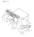
- the lens-measuring portion 22 comprises, as shown in Fig. 3 , a pair of styluses 221 and 222 which are disposed at opposite sides of the uncut lens L and face to each other.
- the rough processing portion 23 comprises, as shown in Fig. 2 , a rough grinder for a plastic lens 231 and a rough grinder for a glass lens 232.
- the bevel and flat grinding portion 24 comprises a grinder for beveled processing and flat processing 241 which comprises a beveled grinding portion having a groove corresponding to the bevel on the grinding face and a flat grinding portion having a flat grinding face.
- the polishing portion 25 comprises a polishing grinder 251.
- These grinders 231, 232, 241 and 251 are disposed at the same rotating shaft.
- the uncut lens L held by the lens-holding unit 21 is pressed against one of these grinders which are rotated by the rotation of the rotating shaft and the processing is conducted in accordance with the selected grinder.
- the grooving portion 26 comprises a grooving tool having an end mill although the grooving tool is not shown in the Fig..
- the peripheral face of the lens L which has been processed to a prescribed peripheral shape is cut into the prescribed depth by the end mill while the lens L is continuously rotated and a groove can be formed.
- the chamfering portion 27 comprises a chamfering tool having a grinding portion having an approximately hemispherical shape although the chamfering tool is not shown in the Fig..
- the edge at the boundary of the peripheral face and the face of the lens L which has been processed by the flat grinding or the beveled grinding is ground by the grinding portion having the approximately hemispherical shape while the lens L is continuously rotated and the chamfering can be conducted.
- the operation panel 3 comprises a display portion 31 for displaying an estimated shape of the lens to be obtained after the processing and various values set for the processing and an input portion 32 for inputting information necessary for processing the uncut lens L and for directing a desired processing.
- the control portion 4 comprises CPU and other devices and controls operations of the apparatus for processing a lens 1 by execution of the control program stored in the memory portion 5.
- the memory portion 4 comprises ROM, RAM and other devices and memorizes the control program of the apparatus for processing a lens 1, data of the image of the lens and other information.
- the mark F indicates a frame tracer which is attached at the outside of the apparatus for processing a lens 1 and can communicate with the apparatus.
- the frame tracer F measures the desired spectacle frame set at the frame tracer and transfers data of the shape of the lens frame expressing the three-dimensional shape of the lens frame to the apparatus for processing a lens 1. Therefore, the apparatus for processing a lens 1 is equipped with an interface of communication therefor.
- the frame tracer F is not a component constituting the apparatus for processing a lens 1 in the Fig., the apparatus for processing a lens 1 may have the frame tracer F as a constituting component.
- a layout display 91 such as that shown in Fig. 9 is displayed in the display portion 31.
- the operator indicates whether the lens to be processed is a lens for the right eye or for the left eye and also indicates in a column 911 that the type of the processing is the bevel processing.
- the operator inputs the data of prescription for the person wearing the spectacle glasses and information of the layout including data of the distance between geometrical centers into a column 912 using the input portion 32.
- the control portion 3 obtains the data of the shape of processing expressing the shape of the lens formed after the rough grinding of the uncut lens L by the calculation based on the input data.
- the operator may indicate the chamfering and/or the grooving as an option for the finishing using the input portion 32.
- Examples of the data of prescription include the pupillary distance (PD), information on the eye point including the height of the eye point relative to the geometrical center of the frame and data expressing the cylinder axis (AX).
- Examples of the data of the distance between geometrical centers include the frame PD (FPD) expressing the distance between the geometrical centers of the lens frames and the distance between lenses (DBL) expressing the distance between lenses (so-called the nose width).
- Examples of the lens data include the value of a curve or the value of a curve for every axial direction of the convex face of the uncut lens, the value of a curve or the value of a curve for every axial direction of the concave face of the uncut lens, the thickness of the center (the optical center or the geometrical center) of the uncut lens, the diameter of the lens (including A size and B size), the shape of the lens (the shape of the near optical center) and the distance between the optical center and the geometrical center.
- the above values of a curve may be approximate values. As the lens data, all these data are not always necessary. The necessary data may be selected and included.
- the lens data may be provided to the apparatus for processing a lens 1 not by the manual input by the operator but through a data communication.
- the operator then indicates the lens type of the uncut lens L in column 913 of the input display 91 using the input portion 32. More specifically, the input portion 32 has a button for selection of the lens type and any one of EX, minus-power, lenticular, plus-power and regular lenses can be selected as the lens type by pushing the button for selection of the lens type.
- the EX lens is selected as an example.
- the control portion 4 obtains the information of the lens type expressing the lens type (the step of obtaining the information of the lens type).
- the information of the lens type may be provided to the apparatus for processing a lens 1 not by the manual input by the operator but from the outside by another means such as communication.
- the high power minus lens and the high power plus lens mean lenses having the maximum thickness of the peripheral edge of about 5 mm or greater after the lens is processed. Since the size of the protruded portion is great in these lenses when the lenses are fitted into frames, it is desired that the bevel is formed at a suitable position.
- the operator then pushes the starting switch of the input portion 32.
- the control portion 3 directs measuring the shape of the uncut lens L based on the data of the shape of processing obtained in step S3.
- the styluses 221 and 222 are moved relative to the uncut lens L held by the holding shaft 211 and 212 in a manner such that the positions of contact of the styluses 221 and 222 on both faces of the uncut lens form loci about the same as that of the position of the peripheral edge of the lens after the processing and the positions of the contact (the positions on the faces of the lens) and the thickness of the lens at the positions of the contact are measured.
- the control portion 4 calculates the locus of the bevel in accordance with the lens type based on the information of the lens type obtained in S5 (the step of calculating the locus of a bevel) and creates the data of the locus of the bevel ( data of the automatically set bevel curve).
- Step S7 is conducted specifically for each lens type selected from “EX" (step S71), “high power minus” (step S72), “lenticular” (step S73), “high power plus” (step S74) and “regular” (step S75).
- the step specific for each lens type will be described later more specifically.
- “regular” is selected (step S75), more specific description will be omitted since the procedures are well known.
- the control portion 4 directs displaying a sample of the condition set for the bevel in the display portion 31 based on the data of the locus of the bevel obtained by the calculation.
- the operator can modify or adjust the condition of the automatically set bevel (including the position and the angle of the bevel) using the input portion 32. When such a modification is made, the data of the locus of the bevel is modified.
- the operator directs starting the processing using the input portion 32.
- the control portion 4 detects the direction of starting the processing, the control portion 4 obtains the data of the rough processing based on the data of the shape of processing obtained in S3.
- the data of the rough processing include data showing margins for grinding in the rough processing.
- the control portion 4 then controls the lens-processing portion 2 so that the rough processing of the uncut lens is conducted in accordance with the obtained data of the rough processing.
- the peripheral portion of the uncut lens L is ground by the rough grinder for a plastic lens 231 or the rough grinder for a glass lens 232.
- the control portion 4 then obtains data of the bevel processing based on the data of the locus of the bevel obtained in step S7 (the modified data of the locus of the bevel when the data have been modified in step S8) and the data of the shape of processing obtained in step S3.
- the control portion 4 forms the bevel based on the data of the bevel processing thus obtained. In this manner, the peripheral edge of the roughly processed lens is processed and the bevel is formed by the finishing grinder of the grinder for beveled processing and flat processing 241 and the bevel groove formed on the finishing grinder.
- the operation returns to step 2.
- the uncut lens for the lens for the left eye is held by chucking and the lens for the left eye is obtained in accordance with the same procedures.
- Step S7 will be described more specifically in the following.
- step S71 In the case where an EX lens is indicated (step S71), the procedures will be described in accordance with the flow chart shown in Fig. 5 with reference to the diagram shown in Fig. 10 .
- the value of the bevel curve K1 is decided based on the value of the curve of the concave face of the EX lens contained in the lens data obtained in step S4 described above (the step of deciding the value of the bevel curve). Specifically, the calculation is different depending on whether the EX lens is a minus-power lens or a plus-power lens.
- the value of the bevel curve K1 is obtained in accordance with one of the following equations:
- e + represents a number of 1 or greater and e - represents a number of 1 or smaller.
- the obtained value of the bevel curve K1 and the radius of curvature of the bevel curve r1 satisfy the following equation: K ⁇ 1 ⁇ 523 / r ⁇ 1 wherein the refractive index of the air is set at 1.0.
- the reference axis of the bevel curve (hereinafter, referred to as the initial reference axis of the bevel curve) is decided in the same direction as the direction of the curvature of the concave face of the EX lens (the step of deciding the initial reference axis of the bevel curve).
- the first reference position m on the peripheral edge in the portion having the minimum thickness at the lower side in the vertical direction of the EX lens (the reference position of the bevel) is decided based on the thickness t1 of the portion having the minimum thickness (the step of deciding the first reference position).
- the first reference position m is expressed by the distance P1 from the end of the peripheral edge at the side of the convex face in the portion having the minimum thickness to the first reference position m.
- P1 is different depending on the thickness t1 of the portion having the minimum thickness and decided as shown in the following:
- the second reference position n on the peripheral edge in the portion having the maximum thickness at the upper side in the vertical direction of the EX lens is decided based on the ratio ( t 2/ t 1) of the thickness t 2 of the portion having the maximum thickness to the thickness t 1 of the portion having the minimum thickness (the step of deciding the second reference position).
- the second reference position n is expressed by the distance H from the position m' corresponding to the first reference position on the peripheral edge in the portion having the maximum thickness to the second reference position n (hereinafter, the distance H being referred to as the value of correction for the reference axis of a curve).
- H a ⁇ t ⁇ 2 / t ⁇ 1 ⁇ t ⁇ 1 - P ⁇ 1 - t ⁇ 1 - P ⁇ 1
- a represents an adjusting coefficient.
- (t2/t1) is 1 or greater.
- the locus of the bevel is decided based on the value of the bevel curve K1, the first reference position m and the angle of inclination of the axis ⁇ (the step of deciding the locus of the bevel). Specifically, the locus of the bevel which has the value of the bevel curve K1 and an axis obtained by inclination of the initial reference axis of the bevel curve by the angle ⁇ in the anti-clockwise direction in Fig. 10 as the reference axis of the curve, is decided. The decided locus of the bevel has the value of the bevel curve K1 and passes through the first reference position m and the second reference position n .
- a suitable locus of the bevel having an excellent balance can be obtained without marked protrusion of the front face of the EX lens from the rim when the EX lens is fitted into the frame.
- step S72 In the case where a high power minus lens is indicated (step S72), the procedures will be described in accordance with the flow chart shown in Fig. 6 with reference to the diagram shown in Fig. 11 .
- the value of the bevel curve K1 is decided based on the value of the curve of the convex face of the high power minus lens contained in the lens data obtained in step S4 described above (the step of deciding the value of the bevel curve). Specifically, the calculation is different depending on the value of the curve C of the convex face of the high power minus lens.
- the value of the bevel curve K1 is obtained in accordance with one of the following equations:
- the reference axis of the bevel curve (hereinafter, referred to as the initial reference axis of the bevel curve) is decided in the same direction as the direction of the curvature of the convex face of the high power minus lens (the step of deciding the initial reference axis of the bevel curve).
- the first reference position m on the peripheral edge in the portion having the minimum thickness at the side of the nose of the person wearing the high power minus lens (the reference position of the bevel) is decided based on the thickness t1 of the portion having the minimum thickness (the step of deciding the first reference position).
- the first reference position m is expressed by the distance P1 from the end of the peripheral edge at the side of the convex face in the portion having the minimum thickness to the first reference position m.
- P1 is different depending on the thickness t 1 of the portion having the minimum thickness and decided as shown in the following:
- the second reference position n on the peripheral edge in the portion having the maximum thickness is decided based on the ratio (t2/t1) of the thickness t 2 of the portion of the high power minus lens having the maximum thickness of the high power minus lens at the side of the ear of the person wearing the high power minus lens to the thickness t 1 of the portion having the minimum thickness (the step of deciding the second reference position).
- the second reference position n is expressed by the distance H from the position m' corresponding to the first reference position on the peripheral edge in the portion having the maximum thickness to the second reference position n (hereinafter, referred to as the value of correction for the reference axis of a curve).
- H P ⁇ 1 ⁇ a ⁇ t ⁇ 2 / t ⁇ 1 - P ⁇ 1
- a represents an adjusting coefficient.
- ( t 2/ t 1) is 1 or greater.
- the locus of the bevel is decided based on the value of the bevel curve K1, the first reference position m and the angle of inclination of the axis ⁇ (the step of deciding the locus of the bevel). Specifically, the locus of the bevel which has the value of the bevel curve K1 and an axis obtained by inclination of the initial reference axis of the bevel curve by an angle ⁇ in the clockwise direction in Fig. 11 as the reference axis of the curve the axis, is decided. The decided locus of the bevel has the value of the bevel curve K1 and passes through the first reference position m and the second reference position n .
- a suitable locus of the bevel having an excellent balance can be obtained without marked protrusion of the back face of the high power minus lens from the rim when the high power minus lens is fitted into the frame.
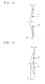
- step S73 In the case where a lenticular lens is indicated (step S73), the procedures will be described in accordance with the flow chart shown in Fig. 7 with reference to the diagram shown in Fig. 12 .
- the obtained value of the bevel curve K1 and the radius of curvature of the curve r 1 satisfy the following equation: K ⁇ 1 ⁇ 523 / r ⁇ 1 wherein the refractive index of the air is set at 1.0.
- the reference position of the bevel m on the peripheral edge in the portion having the minimum thickness at the side of the nose or the ear of the person wearing the lenticular lens is decided based on the thickness t 1 of the portion having the minimum thickness (the step of deciding the first reference position).
- the reference position of the bevel m is expressed by the distance P1 from the end of the peripheral edge at the side of the convex face in the portion having the minimum thickness to the first reference position m.
- P1 is different depending on the thickness t 1 of the portion having the minimum thickness and decided as shown in the following:
- the correction for the value of the curve S is decided based on the ratio ( t 2/ t 1) between the thickness t 1 of the portion of the lenticular lens having the minimum thickness at the side of the nose or the ear of the person wearing the lenticular lens and the thickness t 2 of the portion having the maximum thickness in the vertical direction of the lenticular lens (the step of deciding the correction for the value of the curve).
- a suitable locus of the bevel having an excellent balance can be obtained without marked protrusion of the segment in front of the lens when the lenticular lens is fitted into the frame.
- step S74 the procedures will be described in accordance with the flow chart shown in Fig. 8 with reference to the diagram shown in Fig. 13 .
- the obtained value of the bevel curve K1 and the radius of curvature of the curve r 1 satisfy the following equation: K ⁇ 1 ⁇ 523 / r ⁇ 1 wherein the refractive index of the air is set at 1.0.
- the reference position of the bevel m on the peripheral edge in the portion having the minimum thickness of the high power plus lens is decided based on the thickness t1 of the portion having the minimum thickness (the step of deciding the first reference position).
- the reference position of the bevel m is expressed by the distance P1 from the end of the peripheral edge at the side of the convex face in the portion having the minimum thickness to the first reference position m.
- P1 is different depending on the thickness t 1 of the portion having the minimum thickness and decided as shown in the following:
- the correction for the value of the curve S is decided based on the ratio (C2/C1) of the value of the curve C1 of the concave face to the value of the curve C2 of the convex face of the high power plus lens or based on the value of the curve C2 of the convex face alone (the step of deciding the correction for the value of the curve).
- a suitable locus of the bevel having an excellent balance can be obtained without marked protrusion of the convex face of the high power plus lens in front of the lens when the high power plus lens is fitted into the frame.
- an EX lens is well known to a person skilled in the arts and sometimes called “an E line multifocal lens”
- the locus of the bevel which has heretofore been obtained by the skill and the experience of a skilled operator can be obtained in accordance with the prescribed procedures. Therefore, the suitable bevel can be formed even by a person not skilled in the art.
Landscapes
- Engineering & Computer Science (AREA)
- Mechanical Engineering (AREA)
- Chemical & Material Sciences (AREA)
- Ceramic Engineering (AREA)
- Inorganic Chemistry (AREA)
- Eyeglasses (AREA)
- Grinding And Polishing Of Tertiary Curved Surfaces And Surfaces With Complex Shapes (AREA)
Abstract
Description
- The present invention relates to a method for deciding a bevel curve, a method for deciding a locus of a bevel, a method for processing a lens and an apparatus for processing a lens which is used for conducting these methods.
- Heretofore, for processing an uncut lens into a shape fitting a shape of a lens frame of a spectacle frame, apparatuses for processing a lens have been used. As the apparatus for processing a lens, apparatuses having the so-called function of automatic beveled processing have also been provided. When a regular lens is used as the uncut lens in the processing using this type of the apparatus for processing a lens, after the information necessary for processing the uncut lens including data of the shape of the frame is provided to the apparatus, a locus of a bevel most suitable for the lens is automatically calculated by the apparatus and the bevel is formed along the obtained locus.
- On the other hand, when a special lens is used as the uncut lens in the processing using this type of the apparatus for processing a lens, the position of the apex of the bevel and the bevel curve or the bevel ratio are manually set intentionally while the operator watches the display of simulation.
- However, the manual setting of the locus of a bevel depends on the skill and the experience of the operator to a great degree. Therefore, it is difficult that the bevel is formed at a suitable position without a skilled operator.
- In particular, it is difficult that the most suitable bevel is formed with an excellent balance in special lenses such as a high power minus lens, a high power plus lens, an EX lens and a lenticular lens. Occasionally, when the completed lens is fitted into a lens frame, peripheral edges of the lens protrudes unevenly from the rim and the appearance of the entire spectacle glass becomes poor.
- In recent years, the number of the skilled operator is decreasing. Under these circumstances, technology which enables formation of a suitable bevel in special lenses even by a person not skilled in the art has been desired.
- The present invention has an object of enabling formation of a suitable bevel in special lenses even by a person not skilled in the art.
- As the first aspect, the present invention provides a method for deciding a locus of a bevel in an EX lens which comprises: in a step of deciding a value of a bevel curve, deciding the value of the bevel curve based on a value of a curve of a concave face of the EX lens; in a step of deciding a first reference position, deciding the first reference position on a peripheral edge in a portion having a minimum thickness at a lower side in a vertical direction of the EX lens based on a thickness of the portion having a minimum thickness; in a step of deciding a second reference position, deciding the second reference position on a peripheral edge in a portion having a maximum thickness at an upper side in a vertical direction of the EX lens based on a ratio of a thickness of the portion having a maximum thickness to the thickness of the portion having a minimum thickness and data of a shape of the EX lens to be obtained by the processing; and, in a step of deciding the locus of the bevel, deciding the locus of the bevel based on the value of the bevel curve, the first reference position and the second reference position.
- As the second aspect, the present invention provides a method for deciding a locus of a bevel in an EX lens which comprises: in a step of deciding a value of a bevel curve, deciding the value of the bevel curve based on a value of a curve of a concave face of the EX lens; in a step of deciding an initial reference axis of the bevel curve, deciding the initial reference axis of the bevel curve in a same direction as a direction of a curvature of the concave face of the EX lens; in a step of deciding a reference position of the bevel, deciding the reference position of the bevel on a peripheral edge in a portion having a minimum thickness at a lower side in a vertical direction of the EX lens based on a thickness of the portion having a minimum thickness; in a step of calculating a value of correction for an initial reference axis of the bevel curve, deriving the value of correction for the initial reference axis of the bevel curve based on a ratio of a thickness of a portion having a maximum thickness at an upper side in a vertical direction of the EX lens to a thickness of the portion having a minimum thickness; in a step of calculating an angle of inclination of an axis, deriving the angle of inclination of a reference axis of the bevel curve from a direction of the initial reference axis of the bevel curve based on the value of correction for the initial reference axis of the bevel curve and data of a shape of the EX lens to be obtained by the processing; and, in a step of deciding the locus of the bevel, deciding the locus of the bevel based on the value of the bevel curve, the reference position of the bevel and the angle of inclination of the axis.
- As the third aspect, the present invention provides a method for deciding a locus of a bevel in a high power minus lens which comprises: in a step of deciding a value of a bevel curve, deciding the value of the bevel curve based on a value of a curve of a convex face of the high power minus lens; in a step of deciding a first reference position, deciding the first reference position on a peripheral edge in a portion having a minimum thickness of the high power minus lens at a side of a nose of a person wearing the high power minus lens based on a thickness of the portion having a minimum thickness; in a step of deciding a second reference position, deciding the second reference position on a peripheral edge in a portion having a maximum thickness of the high power minus lens at a side of an ear of a person wearing the high power minus lens based on a ratio of a thickness of the portion having a maximum thickness to the thickness of the portion having a minimum thickness and data of a shape of the high power minus lens to be obtained by the processing; and, in a step of deciding the locus of the bevel, deciding the locus of the bevel based on the value of the bevel curve, the first reference position and the second reference position.
- As the fourth aspect, the present invention provides a method for deciding a locus of a bevel in a high power minus lens which comprises: in a step of deciding a value of a bevel curve, deciding the value of the bevel curve based on a value of a curve of a convex face of the high power minus lens; in a step of deciding an initial reference axis of the bevel curve, deciding the initial reference axis of a bevel curve in a same direction as a direction of a curvature of the convex face of the high power minus lens; in a step of deciding a reference position of the bevel, deciding the reference position of the bevel on a peripheral edge in a portion having a minimum thickness of the high power minus lens at a side of a nose of a person wearing the high power minus lens based on a thickness of the portion having a minimum thickness; in a step of calculating a value of correction for an initial reference axis of the bevel curve, deriving the value of correction for the initial reference axis of the bevel curve based on a ratio of a thickness of a portion having a maximum thickness of the high power minus lens at a side of an ear of a person wearing the high power minus lens and a thickness of the portion having a minimum thickness; in a step of calculating an angle of inclination of an axis, deriving the angle of inclination of a reference axis of the bevel curve from a direction of the initial reference axis of the bevel curve based on the value of correction for the initial reference axis of the bevel curve and data of a shape of the high power minus lens to be obtained by the processing; and, in a step of deciding the locus of a bevel, deciding the locus of the bevel based on the value of the bevel curve, the reference position of the bevel and the angle of inclination of the axis.
- As the fifth aspect, the present invention provides a method for deciding a locus of a bevel in a lenticular lens which comprises: in a step of deciding a value of a bevel curve, deciding the value of the bevel curve based on a value of a curve of a concave face of the lenticular lens; in a step of deciding a reference position of the bevel, deciding the reference position of the bevel on a peripheral edge in a portion having a minimum thickness at a side of a nose or a ear of a person wearing the lenticular lens based on a thickness of the portion having a minimum thickness; in a step of deciding a correction for a value of a curve, deciding the correction for a value of a curve based on a ratio of the thickness of the portion having a minimum thickness of the lenticular lens at a side of a nose or an ear to a thickness of a portion having a maximum thickness of the lenticular lens in a vertical direction; and, in a step of deciding the locus of the bevel, deciding the locus of the bevel which has a value of a curve obtained by adding the correction for a value of a curve to the value of the bevel curve and passes through the reference position of the bevel.
- As the sixth aspect, the present invention provides a method for deciding a locus of a bevel in a high power plus lens which comprises: in a step of deciding a value of a bevel curve, deciding the value of the bevel curve based on a value of a curve of a concave face of the high power plus lens; in a step of deciding a reference position of the bevel, deciding the reference position of the bevel on a peripheral edge in a portion having a minimum thickness of the high power plus lens based on a thickness of the portion having a minimum thickness; in a step of deciding a correction for a value of a curve, deciding the correction for a value of a curve based on a ratio of the value of a curve of the concave face to a value of a curve of a convex face of the high power plus lens or based on the value of a curve of a convex face alone of the high power plus lens; and, in a step of deciding the locus of the bevel, deciding the locus of the bevel which has a value of a curve obtained by adding the correction for a value of a curve to the value of the bevel curve and passes through the reference position of the bevel.
-
- Fig. 1
- shows a block diagram schematically exhibiting the function of the apparatus for processing a lens as an embodiment of the present invention;
- Fig. 2
- shows a perspective diagram schematically exhibiting the construction at the inside of the apparatus for processing a lens as an embodiment of the present invention;
- Fig. 3
- shows a diagram exhibiting the construction around the lens-measuring portion of the apparatus for processing a lens as an embodiment of the present invention;
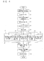
- Fig. 4
- shows a flow chart describing the working of the apparatus for processing a lens as an embodiment of the present invention;
- Fig. 5
- shows a flow chart describing the method for deciding the locus of the bevel of an EX lens;
- Fig. 6
- shows a flow chart describing the method for deciding the locus of the bevel of a high power minus lens;
- Fig. 7
- shows a flow chart describing the method for deciding the locus of the bevel of a lenticular lens;
- Fig. 8
- shows a flow chart describing the method for deciding the locus of the bevel of a plus-power lens;
- Fig. 9
- shows a diagram exhibiting an example of the display in the display portion of the apparatus for processing a lens as an embodiment of the present invention;
- Fig. 10
- shows a diagram describing the method for deciding the locus of the bevel of an EX lens;
- Fig. 11
- shows a diagram describing the method for deciding the locus of the bevel of a high power minus lens;
- Fig. 12
- shows a diagram describing the method for deciding the locus of the bevel of a lenticular lens; and
- Fig. 13
- shows a diagram describing the method for deciding the locus of the bevel of a high power plus lens.
-
Fig. 1 shows a block diagram schematically exhibiting the function of the apparatus for processing a lens as an embodiment of the present invention. The apparatus for processing alens 1 comprises a lens-processing portion 2 in which an uncut lens is processed to provide a shape fitting the lens frame of the spectacle frame, anoperation panel 3, a control portion 4 and amemory portion 5. - The lens-
processing portion 2 comprises a lens-holding unit 21, a lens-measuringportion 22, arough processing portion 23, a beveled andflat grinding portion 24, apolishing portion 25, agrooving portion 26 and achamfering portion 27. - The lens-
holding unit 21 comprises, as shown inFig. 2 , a pair of lens-holding shafts holding shafts holding unit 21. - The lens-
measuring portion 22 comprises, as shown inFig. 3 , a pair ofstyluses styluses - The
rough processing portion 23 comprises, as shown inFig. 2 , a rough grinder for aplastic lens 231 and a rough grinder for aglass lens 232. - The bevel and
flat grinding portion 24 comprises a grinder for beveled processing andflat processing 241 which comprises a beveled grinding portion having a groove corresponding to the bevel on the grinding face and a flat grinding portion having a flat grinding face. - The
polishing portion 25 comprises apolishing grinder 251. - These
grinders holding unit 21 is pressed against one of these grinders which are rotated by the rotation of the rotating shaft and the processing is conducted in accordance with the selected grinder. - The
grooving portion 26 comprises a grooving tool having an end mill although the grooving tool is not shown in the Fig.. The peripheral face of the lens L which has been processed to a prescribed peripheral shape is cut into the prescribed depth by the end mill while the lens L is continuously rotated and a groove can be formed. - The
chamfering portion 27 comprises a chamfering tool having a grinding portion having an approximately hemispherical shape although the chamfering tool is not shown in the Fig.. The edge at the boundary of the peripheral face and the face of the lens L which has been processed by the flat grinding or the beveled grinding is ground by the grinding portion having the approximately hemispherical shape while the lens L is continuously rotated and the chamfering can be conducted. - The
operation panel 3 comprises adisplay portion 31 for displaying an estimated shape of the lens to be obtained after the processing and various values set for the processing and aninput portion 32 for inputting information necessary for processing the uncut lens L and for directing a desired processing. - The control portion 4 comprises CPU and other devices and controls operations of the apparatus for processing a
lens 1 by execution of the control program stored in thememory portion 5. - The memory portion 4 comprises ROM, RAM and other devices and memorizes the control program of the apparatus for processing a
lens 1, data of the image of the lens and other information. - In
Fig. 1 , the mark F indicates a frame tracer which is attached at the outside of the apparatus for processing alens 1 and can communicate with the apparatus. The frame tracer F measures the desired spectacle frame set at the frame tracer and transfers data of the shape of the lens frame expressing the three-dimensional shape of the lens frame to the apparatus for processing alens 1. Therefore, the apparatus for processing alens 1 is equipped with an interface of communication therefor. Although the frame tracer F is not a component constituting the apparatus for processing alens 1 in the Fig., the apparatus for processing alens 1 may have the frame tracer F as a constituting component. - The working of the apparatus for processing a lens will be described in the following with reference to
Fig. 4 . - [S1] Data of the shape of the lens frame of the spectacle frame is obtained from the frame tracer F.
- [S2] The operator sets the uncut lens L at the lens-holding
unit 21 and the holding of the lens is directed using the input portion 342. By this operation, the uncut lens L is held by the lens-holdingunit 21 in a chucked condition. When the uncut lens L is held, the optical center of the uncut lens L is placed in the axial direction of the lens-holdingshafts unit 21. - [S3] At this time, a
layout display 91 such as that shown inFig. 9 is displayed in thedisplay portion 31. In thelayout display 91, using theinput portion 32, the operator indicates whether the lens to be processed is a lens for the right eye or for the left eye and also indicates in acolumn 911 that the type of the processing is the bevel processing. The operator inputs the data of prescription for the person wearing the spectacle glasses and information of the layout including data of the distance between geometrical centers into acolumn 912 using theinput portion 32. When these operations have been conducted, thecontrol portion 3 obtains the data of the shape of processing expressing the shape of the lens formed after the rough grinding of the uncut lens L by the calculation based on the input data. - At this time, the operator may indicate the chamfering and/or the grooving as an option for the finishing using the
input portion 32. - Examples of the data of prescription include the pupillary distance (PD), information on the eye point including the height of the eye point relative to the geometrical center of the frame and data expressing the cylinder axis (AX). Examples of the data of the distance between geometrical centers include the frame PD (FPD) expressing the distance between the geometrical centers of the lens frames and the distance between lenses (DBL) expressing the distance between lenses (so-called the nose width).
- [S4] The operator then inputs the lens data of the uncut lens using the
input portion 32. - Examples of the lens data include the value of a curve or the value of a curve for every axial direction of the convex face of the uncut lens, the value of a curve or the value of a curve for every axial direction of the concave face of the uncut lens, the thickness of the center (the optical center or the geometrical center) of the uncut lens, the diameter of the lens (including A size and B size), the shape of the lens (the shape of the near optical center) and the distance between the optical center and the geometrical center.
- The above values of a curve may be approximate values. As the lens data, all these data are not always necessary. The necessary data may be selected and included.
- The lens data may be provided to the apparatus for processing a
lens 1 not by the manual input by the operator but through a data communication. - [S5] The operator then indicates the lens type of the uncut lens L in
column 913 of theinput display 91 using theinput portion 32. More specifically, theinput portion 32 has a button for selection of the lens type and any one of EX, minus-power, lenticular, plus-power and regular lenses can be selected as the lens type by pushing the button for selection of the lens type. InFig. 5 , the EX lens is selected as an example. - By indication of the lens type of the uncut lens by the operator using the
input portion 32 as shown in the above, the control portion 4 obtains the information of the lens type expressing the lens type (the step of obtaining the information of the lens type). The information of the lens type may be provided to the apparatus for processing alens 1 not by the manual input by the operator but from the outside by another means such as communication. - The high power minus lens and the high power plus lens mean lenses having the maximum thickness of the peripheral edge of about 5 mm or greater after the lens is processed. Since the size of the protruded portion is great in these lenses when the lenses are fitted into frames, it is desired that the bevel is formed at a suitable position.
- [S6] The operator then pushes the starting switch of the
input portion 32. Thecontrol portion 3 directs measuring the shape of the uncut lens L based on the data of the shape of processing obtained in step S3. Thestyluses shaft styluses - [S7] The control portion 4 calculates the locus of the bevel in accordance with the lens type based on the information of the lens type obtained in S5 (the step of calculating the locus of a bevel) and creates the data of the locus of the bevel ( data of the automatically set bevel curve).
- Step S7 is conducted specifically for each lens type selected from "EX" (step S71), "high power minus" (step S72), "lenticular" (step S73), "high power plus" (step S74) and "regular" (step S75). The step specific for each lens type will be described later more specifically. When "regular" is selected (step S75), more specific description will be omitted since the procedures are well known.
- [S8] The control portion 4 directs displaying a sample of the condition set for the bevel in the
display portion 31 based on the data of the locus of the bevel obtained by the calculation. The operator can modify or adjust the condition of the automatically set bevel (including the position and the angle of the bevel) using theinput portion 32. When such a modification is made, the data of the locus of the bevel is modified. - [S9] The operator directs starting the processing using the
input portion 32. When the control portion 4 detects the direction of starting the processing, the control portion 4 obtains the data of the rough processing based on the data of the shape of processing obtained in S3. The data of the rough processing include data showing margins for grinding in the rough processing. The control portion 4 then controls the lens-processing portion 2 so that the rough processing of the uncut lens is conducted in accordance with the obtained data of the rough processing. The peripheral portion of the uncut lens L is ground by the rough grinder for aplastic lens 231 or the rough grinder for aglass lens 232. - [S10] The control portion 4 then obtains data of the bevel processing based on the data of the locus of the bevel obtained in step S7 (the modified data of the locus of the bevel when the data have been modified in step S8) and the data of the shape of processing obtained in step S3. The control portion 4 forms the bevel based on the data of the bevel processing thus obtained. In this manner, the peripheral edge of the roughly processed lens is processed and the bevel is formed by the finishing grinder of the grinder for beveled processing and
flat processing 241 and the bevel groove formed on the finishing grinder. - When the lens for the right eye is obtained in accordance with the above steps, the operation returns to step 2. The uncut lens for the lens for the left eye is held by chucking and the lens for the left eye is obtained in accordance with the same procedures.
- Step S7 will be described more specifically in the following.
- In the case where an EX lens is indicated (step S71), the procedures will be described in accordance with the flow chart shown in
Fig. 5 with reference to the diagram shown inFig. 10 . - [S711] The value of the bevel curve K1 is decided based on the value of the curve of the concave face of the EX lens contained in the lens data obtained in step S4 described above (the step of deciding the value of the bevel curve). Specifically, the calculation is different depending on whether the EX lens is a minus-power lens or a plus-power lens. The value of the bevel curve K1 is obtained in accordance with one of the following equations:
- In the case of a plus-power lens:


In the case of a minus-power lens:
- In the above equations, e+ represents a number of 1 or greater and e- represents a number of 1 or smaller.
- When the refractive index of the lens material is 1.523, the obtained value of the bevel curve K1 and the radius of curvature of the bevel curve r1 satisfy the following equation:

wherein the refractive index of the air is set at 1.0. - [S712] In the above calculation, the reference axis of the bevel curve (hereinafter, referred to as the initial reference axis of the bevel curve) is decided in the same direction as the direction of the curvature of the concave face of the EX lens (the step of deciding the initial reference axis of the bevel curve).
- [S713] The first reference position m on the peripheral edge in the portion having the minimum thickness at the lower side in the vertical direction of the EX lens (the reference position of the bevel) is decided based on the thickness t1 of the portion having the minimum thickness (the step of deciding the first reference position). In this step, the first reference position m is expressed by the distance P1 from the end of the peripheral edge at the side of the convex face in the portion having the minimum thickness to the first reference position m. Specifically, P1 is different depending on the thickness t1 of the portion having the minimum thickness and decided as shown in the following:
- When t1=2.4 mm or smaller, P1=t1/2
- When t1=2.4∼4.0 mm, P1=1.2
- When t1=4.0 mm or greater, P1=3×t1/10
- [S714] The second reference position n on the peripheral edge in the portion having the maximum thickness at the upper side in the vertical direction of the EX lens is decided based on the ratio (t2/t1) of the thickness t2 of the portion having the maximum thickness to the thickness t1 of the portion having the minimum thickness (the step of deciding the second reference position). The second reference position n is expressed by the distance H from the position m' corresponding to the first reference position on the peripheral edge in the portion having the maximum thickness to the second reference position n (hereinafter, the distance H being referred to as the value of correction for the reference axis of a curve). Specifically, the value of correction for the reference axis of a curve H is obtained in accordance with the following equation:

wherein a represents an adjusting coefficient. (t2/t1) is 1 or greater. When a×(t2/t1) is 1 or smaller, always ax(t2/t1)=1. - [S715] The angle of inclination θ of the axis from the direction of the initial reference axis of the bevel curve is calculated based on the value of correction for the reference axis of a curve H and the B size (the vertical axis of the lens shape) B contained in the lens data (the step of calculating the angle of inclination of the axis). Specifically, the angle of inclination of the axis is calculated in accordance with the following equation:

- [S716] The locus of the bevel is decided based on the value of the bevel curve K1, the first reference position m and the angle of inclination of the axis θ (the step of deciding the locus of the bevel). Specifically, the locus of the bevel which has the value of the bevel curve K1 and an axis obtained by inclination of the initial reference axis of the bevel curve by the angle θ in the anti-clockwise direction in
Fig. 10 as the reference axis of the curve, is decided. The decided locus of the bevel has the value of the bevel curve K1 and passes through the first reference position m and the second reference position n. - In accordance with the above procedures, a suitable locus of the bevel having an excellent balance can be obtained without marked protrusion of the front face of the EX lens from the rim when the EX lens is fitted into the frame.
- In the case where a high power minus lens is indicated (step S72), the procedures will be described in accordance with the flow chart shown in
Fig. 6 with reference to the diagram shown inFig. 11 . - [S721] The value of the bevel curve K1 is decided based on the value of the curve of the convex face of the high power minus lens contained in the lens data obtained in step S4 described above (the step of deciding the value of the bevel curve). Specifically, the calculation is different depending on the value of the curve C of the convex face of the high power minus lens. The value of the bevel curve K1 is obtained in accordance with one of the following equations:
- When the value of the curve C of the convex face is 2.0 or smaller,

- When the value of the curve C of the convex face is 2.0∼4.0,

- When the value of the curve C of the convex face is 4.0∼7.0,

- When the value of the curve C of the convex face is 7.0 or greater,

- When the refractive index of the lens material is 1.523, the obtained value of a bevel curve K1 and the radius of curvature of the curve r1 satisfy the following equation:

wherein the refractive index of the air is set at 1.0. - [S722] In the above calculation, the reference axis of the bevel curve (hereinafter, referred to as the initial reference axis of the bevel curve) is decided in the same direction as the direction of the curvature of the convex face of the high power minus lens (the step of deciding the initial reference axis of the bevel curve).
- [S723] The first reference position m on the peripheral edge in the portion having the minimum thickness at the side of the nose of the person wearing the high power minus lens (the reference position of the bevel) is decided based on the thickness t1 of the portion having the minimum thickness (the step of deciding the first reference position). In this step, the first reference position m is expressed by the distance P1 from the end of the peripheral edge at the side of the convex face in the portion having the minimum thickness to the first reference position m. Specifically, P1 is different depending on the thickness t1 of the portion having the minimum thickness and decided as shown in the following:
- When t1=2.4 mm or smaller, P1=t1/2
- When t1=2.4∼4.0 mm, P1=1.2
- When t1=4.0 mm or greater, P1=3×t1/10
- [S724] The second reference position n on the peripheral edge in the portion having the maximum thickness is decided based on the ratio (t2/t1) of the thickness t2 of the portion of the high power minus lens having the maximum thickness of the high power minus lens at the side of the ear of the person wearing the high power minus lens to the thickness t1 of the portion having the minimum thickness (the step of deciding the second reference position). The second reference position n is expressed by the distance H from the position m' corresponding to the first reference position on the peripheral edge in the portion having the maximum thickness to the second reference position n (hereinafter, referred to as the value of correction for the reference axis of a curve). Specifically, the value of correction for the reference axis of a curve H is obtained in accordance with the following equation:

wherein a represents an adjusting coefficient. (t2/t1) is 1 or greater. When a×(t2/t1) is 1 or smaller, always a×(t2/t1)=1. - [S725] The angle of inclination θ of the axis from the direction of the initial reference axis of the bevel curve is calculated based on the value of correction for the reference axis of a curve H and the A size (the horizontal axis of the lens shape) A contained in the lens data (the step of calculating the angle of inclination of the axis). Specifically, the angle of inclination of the axis is calculated in accordance with the following equation:

- [S726] The locus of the bevel is decided based on the value of the bevel curve K1, the first reference position m and the angle of inclination of the axis θ (the step of deciding the locus of the bevel). Specifically, the locus of the bevel which has the value of the bevel curve K1 and an axis obtained by inclination of the initial reference axis of the bevel curve by an angle θ in the clockwise direction in
Fig. 11 as the reference axis of the curve the axis, is decided. The decided locus of the bevel has the value of the bevel curve K1 and passes through the first reference position m and the second reference position n. - In accordance with the above procedures, a suitable locus of the bevel having an excellent balance can be obtained without marked protrusion of the back face of the high power minus lens from the rim when the high power minus lens is fitted into the frame.
- In the case where a lenticular lens is indicated (step S73), the procedures will be described in accordance with the flow chart shown in
Fig. 7 with reference to the diagram shown inFig. 12 . - [S731] The value of the bevel curve K1 is decided based on the value of the curve of the concave face of the lenticular lens contained in the lens data obtained in step S4 described above (the step of deciding the value of the bevel curve). Specifically, the value of the bevel curve K1 is obtained in accordance with the following equation:

In the above equations, e represents a number of 1 or greater. - When the refractive index of the lens material is 1.523, the obtained value of the bevel curve K1 and the radius of curvature of the curve r1 satisfy the following equation:

wherein the refractive index of the air is set at 1.0. - [S732] The reference position of the bevel m on the peripheral edge in the portion having the minimum thickness at the side of the nose or the ear of the person wearing the lenticular lens is decided based on the thickness t1 of the portion having the minimum thickness (the step of deciding the first reference position). In this step, the reference position of the bevel m is expressed by the distance P1 from the end of the peripheral edge at the side of the convex face in the portion having the minimum thickness to the first reference position m. Specifically, P1 is different depending on the thickness t1 of the portion having the minimum thickness and decided as shown in the following:
- When t1=2.4 mm or smaller, P1=t1/2
- When t1=2.4∼4.0 mm, P1=1.2
- When t1=4.0 mm or greater, P1=3×t1/10
- [S733] The correction for the value of the curve S is decided based on the ratio (t2/t1) between the thickness t1 of the portion of the lenticular lens having the minimum thickness at the side of the nose or the ear of the person wearing the lenticular lens and the thickness t2 of the portion having the maximum thickness in the vertical direction of the lenticular lens (the step of deciding the correction for the value of the curve). Specifically, the correction for the value of the curve S is obtained in accordance with the following equation:

wherein a represents an adjusting coefficient. (t2/t1) is 1 or greater. When a×(t2/t1) is 1 or smaller, always a×(t2/t1)=1. - [S734] The locus of the bevel which has the value of the curve K2 (=S+K1) obtained by adding the correction for the value of the curve S to the value of the bevel curve K1 and passes through the reference position of the bevel m, is decided (the step of deciding the locus of the bevel).
- In accordance with the above procedures, a suitable locus of the bevel having an excellent balance can be obtained without marked protrusion of the segment in front of the lens when the lenticular lens is fitted into the frame.
- In the case where a power lens is indicated (step S74), the procedures will be described in accordance with the flow chart shown in
Fig. 8 with reference to the diagram shown inFig. 13 . - [S741] The value of the bevel curve K1 is decided based on the value of the curve of the concave face of the high power plus lens contained in the lens data obtained in the above (the step of deciding the value of the bevel curve). Specifically, the value of the bevel curve K1 is obtained in accordance with the following equation:

In the above equations, e represents a number of 1 or greater. - When the refractive index of the lens material is 1.523, the obtained value of the bevel curve K1 and the radius of curvature of the curve r1 satisfy the following equation:

wherein the refractive index of the air is set at 1.0. - [S742] The reference position of the bevel m on the peripheral edge in the portion having the minimum thickness of the high power plus lens is decided based on the thickness t1 of the portion having the minimum thickness (the step of deciding the first reference position). In this step, the reference position of the bevel m is expressed by the distance P1 from the end of the peripheral edge at the side of the convex face in the portion having the minimum thickness to the first reference position m. Specifically, P1 is different depending on the thickness t1 of the portion having the minimum thickness and decided as shown in the following:
- When t1=2.4 mm or smaller, P1=t1/2
- When t1=2.4∼4.0 mm, P1=1.2
- When t1=4.0 mm or greater, P1=3∼t1/10
- [S743] The correction for the value of the curve S is decided based on the ratio (C2/C1) of the value of the curve C1 of the concave face to the value of the curve C2 of the convex face of the high power plus lens or based on the value of the curve C2 of the convex face alone (the step of deciding the correction for the value of the curve). Specifically, the correction for the value of the curve S is obtained in accordance with the following equation:

wherein a represents an adjusting coefficient. (C2/C1) is 1 or greater. When a×(C2/C1) is 1 or smaller, always a×(C2/C1)=1. - [S744] The locus of the bevel which has the value of the curve K2 (=S+K1) obtained by adding the correction for the value of the curve S to the value of the bevel curve K1 and passes through the reference position of the bevel m, is decided (the step of deciding the locus of the bevel).
- In accordance with the above procedures, a suitable locus of the bevel having an excellent balance can be obtained without marked protrusion of the convex face of the high power plus lens in front of the lens when the high power plus lens is fitted into the frame.
- Incidentally "an EX lens" is well known to a person skilled in the arts and sometimes called "an E line multifocal lens"
- In accordance with the present invention, the locus of the bevel which has heretofore been obtained by the skill and the experience of a skilled operator can be obtained in accordance with the prescribed procedures. Therefore, the suitable bevel can be formed even by a person not skilled in the art.
-
- 1:
- An apparatus for processing a lens;
- 2:
- a lens-processing portion (a means for the beveled processing);
- 31:
- a display portion;
- 32:
- an input portion;
- 4:
- a control portion; and
- 5:
- a memory portion.
Claims (18)
- A method for deciding a locus of a bevel in a high power plus lens which comprises:in a step of deciding a value of a bevel curve, deciding the value of the bevel curve based on a value of a curve of a concave face of the high power plus lens;in a step of deciding a reference position of the bevel, deciding the reference position of the bevel on a peripheral edge in a portion having a minimum thickness of the high power plus lens based on a thickness of the portion having a minimum thickness;in a step of deciding a correction for a value of a curve, deciding the correction for a value of a curve based on a ratio of the value of a curve of the concave face to a value of a curve of a convex face of the high power plus lens or based on the value of a curve of a convex face alone of the high power plus lens; andin a step of deciding the locus of the bevel, deciding the locus of the bevel which has a value of a curve obtained by adding the correction for a value of a curve to the value of the bevel curve and passes through the reference position of the bevel.
- An apparatus for processing a lens which comprises:a means for deciding a value of a bevel curve which decides the value of the bevel curve based on a value of a curve of a concave face of a high power plus lens;a means for deciding a reference position of the bevel which decides the reference position of the bevel on a peripheral edge in a portion having a minimum thickness of the high power plus lens based on a thickness of the portion having a minimum thickness;a means for deciding a correction for a value of a curve which decides the correction for a value of a curve based on a ratio of the value of a curve of the concave face to a value of a curve of a convex face of the high power plus lens or based on the value of a curve of a convex face alone of the high power plus lens;a means for deciding the locus of the bevel which decides the locus of the bevel which has a value of a curve obtained by adding the correction for a value of a curve to the value of the bevel curve and passes through the reference position of the bevel; anda means for forming the bevel which forms the bevel along the locus of the bevel decided by the means for deciding the locus of the bevel.
- A method for deciding a bevel curve in an EX lens which comprises a step of deciding a value of the bevel curve based on a value of a curve of a concave face of the EX lens.
- A method for deciding a bevel curve in a high power minus lens which comprises a step of deciding a value of the bevel curve based on a value of a curve of a convex face of the high power minus lens.
- A method for deciding a bevel curve in a lenticular lens which comprises a step of deciding a value of the bevel curve based on a value of a curve of a cave face of the lenticular lens.
- A method for deciding a bevel curve in a high power plus lens which comprises a step of deciding a value of the bevel curve based on a value of a curve of a concave face of the high power plus lens.
- A method for deciding a locus of a bevel in an EX lens which comprises:in a step of deciding a value of a bevel curve, deciding the value of the bevel curve based on a value of a curve of a concave face of the EX lens;in a step of deciding a first reference position, deciding the first reference position on a peripheral edge in a portion having a minimum thickness at a lower side in a vertical direction of the EX lens based on a thickness of the portion having a minimum thickness;in a step of deciding a second reference position, deciding the second reference position on a peripheral edge in a portion having a maximum thickness at an upper side in a vertical direction of the EX lens based on a ratio of a thickness of the portion having a maximum thickness to the thickness of the portion having a minimum thickness and data of a shape of the EX lens to be obtained by the processing; and,in a step of deciding the locus of the bevel, deciding the locus of the bevel based on the value of the bevel curve, the first reference position and the second reference position.
- A method for deciding a locus of a bevel in an EX lens which comprises:in a step of deciding a value of a bevel curve, deciding the value of the bevel curve based on a value of a curve of a concave face of the EX lens;in a step of deciding an initial reference axis of the bevel curve, deciding the initial reference axis of the bevel curve in a same direction as a direction of a curvature of the concave face of the EX lens;in a step of deciding a reference position of the bevel, deciding the reference position of the bevel on a peripheral edge in a portion having a minimum thickness at a lower side in a vertical direction of the EX lens based on a thickness of the portion having a minimum thickness;in a step of calculating a value of correction for an initial reference axis of the bevel curve, deriving the value of correction for the initial reference axis of the bevel curve based on a ratio of a thickness of a portion having a maximum thickness at an upper side in a vertical direction of the EX lens to a thickness of the portion having a minimum thickness;in a step of calculating an angle of inclination of an axis, deriving the angle of inclination of a reference axis of the bevel curve from a direction of the initial reference axis of the bevel curve based on the value of correction for the initial reference axis of the bevel curve and data of a shape of the EX lens to be obtained by the processing; and,in a step of deciding the locus of the bevel, deciding the locus of the bevel based on the value of the bevel curve, the reference position of the bevel and the angle of inclination of the axis.
- A method for deciding a locus of a bevel in a high power minus lens which comprises:in a step of deciding a value of a bevel curve, deciding the value of the bevel curve based on a value of a curve of a convex face of the high power minus lens;in a step of deciding a first reference position, deciding the first reference position on a peripheral edge in a portion having a minimum thickness of the high power minus lens at a side of a nose of a person wearing the high power minus lens based on a thickness of the portion having a minimum thickness;in a step of deciding a second reference position, deciding the second reference position on a peripheral edge in a portion having a maximum thickness of the high power minus lens at a side of an ear of a person wearing the high power minus lens based on a ratio of a thickness of the portion having a maximum thickness to the thickness of the portion having a minimum thickness and data of a shape of the high power minus lens to be obtained by the processing; and,in a step of deciding the locus of the bevel, deciding the locus of the bevel based on the value of the bevel curve, the first reference position and the second reference position.
- A method for deciding a locus of a bevel in a high power minus lens which comprises:in a step of deciding a value of a bevel curve, deciding the value of the bevel curve based on a value of a curve of a convex face of the high power minus lens;in a step of deciding an initial reference axis of the bevel curve, deciding the initial reference axis of a bevel curve in a same direction as a direction of a curvature of the convex face of the high power minus lens;in a step of deciding a reference position of the bevel, deciding the reference position of the bevel on a peripheral edge in a portion having a minimum thickness of the high power minus lens at a side of a nose of a person wearing the high power minus lens based on a thickness of the portion having a minimum thickness;in a step of calculating a value of correction for an initial reference axis of the bevel curve, deriving the value of correction for the initial reference axis of the bevel curve based on a ratio of a thickness of a portion having a maximum thickness of the high power minus lens at a side of an ear of a person wearing the high power minus lens and a thickness of the portion having a minimum thickness;in a step of calculating an angle of inclination of an axis, deriving the angle of inclination of a reference axis of the bevel curve from a direction of the initial reference axis of the bevel curve based on the value of correction for the initial reference axis of the bevel curve and data of a shape of the high power minus lens to be obtained by the processing; andin a step of deciding the locus of a bevel, deciding the locus of the bevel based on the value of the bevel curve, the reference position of the bevel and the angle of inclination of the axis.
- A method for deciding a locus of a bevel in a lenticular lens which comprises:in a step of deciding a value of a bevel curve, deciding the value of the bevel curve based on a value of a curve of a concave face of the lenticular lens;in a step of deciding a reference position of the bevel, deciding the reference position of the bevel on a peripheral edge in a portion having a minimum thickness at a side of a nose or a ear of a person wearing the lenticular lens based on a thickness of the portion having a minimum thickness;in a step of deciding a correction for a value of a curve, deciding the correction for a value of a curve based on a ratio of the thickness of the portion having a minimum thickness of the lenticular lens at a side of a nose or an ear to a thickness of a portion having a maximum thickness of the lenticular lens in a vertical direction; andin a step of deciding the locus of the bevel, deciding the locus of the bevel which has a value of a curve obtained by adding the correction for a value of a curve to the value of the bevel curve and passes through the reference position of the bevel.
- A method for processing a lens which comprises forming a bevel along a locus of a bevel decided in accordance with a method for deciding a locus of a bevel described in Claim 1 or any one of Claims 7 to 11.
- A spectacle lens obtained in accordance with a method for processing a lens described in Claim 12.
- An apparatus for processing a lens which comprises:a means for deciding a value of a bevel curve which decides the value of the bevel curve based on a value of a curve of a concave face of an EX lens;a means for deciding a first reference position which decides the first reference position on a peripheral edge in a portion having a minimum thickness at a lower side in a vertical direction of the EX lens based on a thickness of the portion having a minimum thickness;a means for deciding a second reference position which decides the second reference position on a peripheral edge in a portion having a maximum thickness at an upper side in a vertical direction of the EX lens based on a ratio of a thickness of the portion having a maximum thickness to the thickness of the portion having a minimum thickness and data of a shape of the EX lens to be obtained by the processing;a means for deciding the locus of the bevel which decides the locus of the bevel based on the value of the bevel curve, the first reference position and the second reference position; anda means for forming the bevel which forms the bevel along the locus of the bevel decided by the means for deciding the locus of the bevel.
- An apparatus for processing a lens which comprises:a means for deciding a value of a bevel curve which decides the value of the bevel curve based on a value of a curve of a concave face of an EX lens;a means for deciding an initial reference axis of the bevel curve which decides the initial reference axis of the bevel curve in a same direction as a direction of a curvature of the concave face of the EX lens;a means for deciding a reference position of the bevel which decides the reference position of the bevel on a peripheral edge in a portion having a minimum thickness at a lower side in a vertical direction of the EX lens based on a thickness of the portion having a minimum thickness;a means for calculating a value of correction for an initial reference axis of the bevel curve which derives the value of correction for the initial reference axis of the bevel curve based on a ratio of a thickness of a portion having a maximum thickness at an upper side in a vertical direction of the EX lens to a thickness of the portion having a minimum thickness;a means for calculating an angle of inclination of an axis which derives the angle of inclination of a reference axis of the bevel curve from a direction of the initial reference axis of the bevel curve based on the value of correction for the initial reference axis of the bevel curve and data of a shape of the EX lens to be obtained by the processing;a means for deciding a locus of the bevel which decides the locus of the bevel based on the value of the bevel curve, the reference position of the bevel and the angle of inclination of the axis; anda means for forming the bevel which forms the bevel along the locus of the bevel decided by the means for deciding the locus of the bevel.
- An apparatus for processing a lens which comprises:a means for deciding a value of a bevel curve which decides the value of the bevel curve based on a value of a curve of a convex face of a high power minus lens;a means for deciding a first reference position which decides the first reference position on a peripheral edge in a portion having a minimum thickness of the high power minus lens at a side of a nose of a person wearing the high power minus lens based on a thickness of the portion having a minimum thickness;a means for deciding a second reference position which decides the second reference position on a peripheral edge in a portion having a maximum thickness of the high power minus lens at a side of an ear of a person wearing the high power minus lens based on a ratio of a thickness of the portion having a maximum thickness to the thickness of the portion having a minimum thickness and data of a shape of the high power minus lens to be obtained by the processing;a means for deciding the locus of the bevel which decides the locus of the bevel based on the value of the bevel curve, the first reference position and the second reference position; anda means for forming the bevel which forms the bevel along the locus of the bevel decided by the means for deciding the locus of the bevel.
- An apparatus for processing a lens which comprises:a means for deciding a value of a bevel curve which decides the value of the bevel curve based on a value of a curve of a convex face of a high power minus lens;a means for deciding an initial reference axis of the bevel curve which decides the initial reference axis of a bevel curve in a same direction as a direction of a curvature of the convex face of the high power minus lens;a means for deciding a reference position of the bevel which decides the reference position of the bevel on a peripheral edge in a portion having a minimum thickness of the high power minus lens at a side of a nose of a person wearing the high power minus lens based on a thickness of the portion having a minimum thickness;a means for calculating a value of correction for an initial reference axis of the bevel curve which derives the value of correction for the initial reference axis of the bevel curve based on a ratio of a thickness of a portion having a maximum thickness of the high power minus lens at a side of an ear of a person wearing the high power minus lens and a thickness of the portion having a minimum thickness;a means for calculating an angle of inclination of an axis which derives the angle of inclination of a reference axis of the bevel curve from a direction of the initial reference axis of the bevel curve based on the value of correction for the initial reference axis of the bevel curve and data of a shape of the high power minus lens to be obtained by the processing;a means for deciding the locus of a bevel which decides the locus of the bevel based on the value of the bevel curve, the reference position of the bevel and the angle of inclination of the axis; anda means for forming the bevel which forms the bevel along the locus of the bevel decided by the means for deciding the locus of the bevel.
- An apparatus for processing a lens which comprises:a means for deciding a value of a bevel curve which decides the value of the bevel curve based on a value of a curve of a concave face of a lenticular lens;a means for deciding a reference position of the bevel which decides the reference position of the bevel on a peripheral edge in a portion having a minimum thickness at a side of a nose or a ear of a person wearing the lenticular lens based on a thickness of the portion having a minimum thickness;a means for deciding a correction for a value of a curve which decides the correction for a value of a curve based on a ratio of the thickness of the portion having a minimum thickness of the lenticular lens at a side of a nose or an ear to a thickness of a portion having a maximum thickness of the lenticular lens in a vertical direction;a means for deciding the locus of the bevel which decides the locus of the bevel which has a value of a curve obtained by adding the correction for a value of a curve to the value of the bevel curve and passes through the reference position of the bevel; anda means for forming the bevel which forms the bevel along the locus of the bevel decided by the means for deciding the locus of the bevel.
Applications Claiming Priority (2)
| Application Number | Priority Date | Filing Date | Title |
|---|---|---|---|
| JP2002105229A JP4562343B2 (en) | 2002-04-08 | 2002-04-08 | EX-type multifocal lens bevel locus determination method and EX-type multifocal lens processing apparatus |
| EP03007793A EP1352712B1 (en) | 2002-04-08 | 2003-04-04 | Method for deciding a bevel curve, method for deciding a locus of a bevel, method for processing a lens and apparatus for processing a lens |
Related Parent Applications (3)
| Application Number | Title | Priority Date | Filing Date |
|---|---|---|---|
| EP03007793.7 Division | 2003-04-04 | ||
| EP03007793 Previously-Filed-Application | 2003-04-04 | ||
| EP03007793A Division EP1352712B1 (en) | 2002-04-08 | 2003-04-04 | Method for deciding a bevel curve, method for deciding a locus of a bevel, method for processing a lens and apparatus for processing a lens |
Publications (2)
| Publication Number | Publication Date |
|---|---|
| EP2052814A1 true EP2052814A1 (en) | 2009-04-29 |
| EP2052814B1 EP2052814B1 (en) | 2013-09-11 |
Family
ID=28449899
Family Applications (2)
| Application Number | Title | Priority Date | Filing Date |
|---|---|---|---|
| EP03007793A Expired - Lifetime EP1352712B1 (en) | 2002-04-08 | 2003-04-04 | Method for deciding a bevel curve, method for deciding a locus of a bevel, method for processing a lens and apparatus for processing a lens |
| EP08006394.4A Expired - Lifetime EP2052814B1 (en) | 2002-04-08 | 2003-04-04 | Method for deciding a bevel curve, method for deciding a locus of a bevel, method for processing a lens and apparatus for processing a lens |
Family Applications Before (1)
| Application Number | Title | Priority Date | Filing Date |
|---|---|---|---|
| EP03007793A Expired - Lifetime EP1352712B1 (en) | 2002-04-08 | 2003-04-04 | Method for deciding a bevel curve, method for deciding a locus of a bevel, method for processing a lens and apparatus for processing a lens |
Country Status (6)
| Country | Link |
|---|---|
| US (5) | US6935924B2 (en) |
| EP (2) | EP1352712B1 (en) |
| JP (1) | JP4562343B2 (en) |
| KR (1) | KR100496561B1 (en) |
| CN (1) | CN1283416C (en) |
| AT (1) | ATE535347T1 (en) |
Cited By (1)
| Publication number | Priority date | Publication date | Assignee | Title |
|---|---|---|---|---|
| EP3575033A1 (en) * | 2018-05-31 | 2019-12-04 | Nidek Co., Ltd. | Processing control data acquiring apparatus, processing control data acquiring method and processing control data acquiring program |
Families Citing this family (17)
| Publication number | Priority date | Publication date | Assignee | Title |
|---|---|---|---|---|
| JP4774203B2 (en) * | 2004-10-01 | 2011-09-14 | 株式会社ニデック | Eyeglass lens processing equipment |
| FR2878971B1 (en) * | 2004-12-03 | 2007-04-20 | Essilor Int | METHOD AND DEVICE FOR AUTOMATICALLY PREPARING THE MOUNTING OF AN OPHTHALMIC LENS |
| FR2878972B1 (en) * | 2004-12-03 | 2007-02-16 | Essilor Int | METHOD AND DEVICE FOR AUTOMATICALLY PREPARING THE MOUNTING OF AN OPHTHALMIC LENS |
| FR2878970B1 (en) * | 2004-12-03 | 2007-04-06 | Essilor Int | DEVICE FOR AUTOMATICALLY PREPARING THE MOUNTING OF OPHTHALMIC LENSES FOR THE MANAGEMENT OF MULTIPLE LENSES SIMULTANEOUSLY |
| FR2878975B1 (en) * | 2004-12-03 | 2007-02-16 | Essilor Int | METHOD AND DEVICE FOR PREPARING THE MOUNTING OF A JOB OF TWO OPHTHALMIC LENSES OF THE SAME PAIR OF EYEWEAR |
| JP4446934B2 (en) * | 2005-06-30 | 2010-04-07 | 株式会社ニデック | Eyeglass lens processing equipment |
| JP2007203423A (en) * | 2006-02-03 | 2007-08-16 | Nidek Co Ltd | Spectacle lens peripheral fringe working device |
| FR2904703B1 (en) * | 2006-08-04 | 2008-12-12 | Essilor Int | PAIR OF OPHTHALMIC GLASSES AND METHOD OF FORMING A PERIPHERAL RIB OF EMBOITEMENT ON THE SINGING OF A LENS |
| JP4988823B2 (en) * | 2007-03-16 | 2012-08-01 | Hoya株式会社 | Edge-grinding method for eyeglass lenses |
| JP5073345B2 (en) * | 2007-03-30 | 2012-11-14 | 株式会社ニデック | Eyeglass lens processing equipment |
| JP5134346B2 (en) * | 2007-11-30 | 2013-01-30 | 株式会社ニデック | Eyeglass lens peripheral processing equipment |
| JP5209358B2 (en) * | 2008-03-31 | 2013-06-12 | 株式会社ニデック | Bend locus setting method and spectacle lens processing apparatus |
| WO2012045412A1 (en) * | 2010-10-04 | 2012-04-12 | Schneider Gmbh & Co. Kg | Apparatus and method for working an optical lens and also a transporting container for optical lenses |
| BR112014013687B1 (en) * | 2011-12-08 | 2021-12-21 | Hoya Corporation | LENS CUTTING SYSTEM, AND METHOD TO MANUFACTURE AN EYEWEAR LENS |
| JP6127530B2 (en) | 2013-01-17 | 2017-05-17 | 株式会社ニデック | Eyeglass lens processing apparatus and processing control data creation program |
| US12000739B2 (en) | 2021-04-22 | 2024-06-04 | Analog Devices, Inc. | Lever based differential capacitive strain gauge with acceleration rejection |
| CN116984958B (en) * | 2023-09-26 | 2023-12-22 | 南通蓬盛机械有限公司 | Optical sighting telescope fine grinding process control method and system |
Citations (5)
| Publication number | Priority date | Publication date | Assignee | Title |
|---|---|---|---|---|
| EP0432078A2 (en) * | 1989-10-27 | 1991-06-12 | Indo Internacional S.A. | Lens bevelling machine |
| EP0479683A2 (en) * | 1990-10-05 | 1992-04-08 | Kabushiki Kaisha TOPCON | Lens grinding apparatus |
| EP0899059A2 (en) * | 1997-08-29 | 1999-03-03 | Nidek Co., Ltd. | Eyeglass lens grinding machine |
| EP0953405A2 (en) * | 1998-04-30 | 1999-11-03 | Nidek Co., Ltd. | Optical lens grinding apparatus |
| US20010035933A1 (en) * | 2000-02-01 | 2001-11-01 | Toshihiro Iwai | Apparatus for displaying lens contour, apparatus for processing lens contour data, and apparatus for grinding edge of eyeglass lens with the same |
Family Cites Families (10)
| Publication number | Priority date | Publication date | Assignee | Title |
|---|---|---|---|---|
| US35933A (en) * | 1862-07-22 | Improved can for preserving fruits, sgc | ||
| JP4046789B2 (en) * | 1996-10-31 | 2008-02-13 | 株式会社ニデック | Eyeglass lens grinding machine and eyeglass lens grinding method |
| JPH10277903A (en) * | 1997-03-31 | 1998-10-20 | Nidek Co Ltd | Glasses lens layout input device and lens grinding machine |
| EP1938923B1 (en) * | 1997-08-01 | 2012-06-13 | Nidek Co., Ltd. | Method of grinding eyeglass lens, and eyeglass lens grinding apparatus |
| DE19804542C5 (en) * | 1998-02-05 | 2009-04-30 | Wernicke & Co Gmbh | Method and device for processing spectacle lenses |
| US6328630B1 (en) * | 1998-10-05 | 2001-12-11 | Hoya Corporation | Eyeglass lens end face machining method |
| JP4087526B2 (en) * | 1999-03-08 | 2008-05-21 | 株式会社トプコン | Eyeglass lens bevel shape display device, lens peripheral processing method using the display device, and lens peripheral processing device |
| ATE390233T1 (en) * | 1999-08-06 | 2008-04-15 | Hoya Corp | EYEWEAR LENS PROCESSING METHOD AND APPARATUS |
| JP2001277086A (en) * | 2000-03-31 | 2001-10-09 | Topcon Corp | Lens peripheral processing equipment |
| JP3961196B2 (en) * | 2000-06-15 | 2007-08-22 | 株式会社ニデック | Eyeglass lens processing equipment |
-
2002
- 2002-04-08 JP JP2002105229A patent/JP4562343B2/en not_active Expired - Fee Related
-
2003
- 2003-03-14 KR KR10-2003-0016107A patent/KR100496561B1/en not_active Expired - Fee Related
- 2003-04-04 EP EP03007793A patent/EP1352712B1/en not_active Expired - Lifetime
- 2003-04-04 AT AT03007793T patent/ATE535347T1/en active
- 2003-04-04 EP EP08006394.4A patent/EP2052814B1/en not_active Expired - Lifetime
- 2003-04-04 US US10/406,580 patent/US6935924B2/en not_active Expired - Fee Related
- 2003-04-08 CN CNB031095259A patent/CN1283416C/en not_active Expired - Fee Related
-
2004
- 2004-07-27 US US10/899,080 patent/US6887134B2/en not_active Expired - Lifetime
-
2005
- 2005-06-30 US US11/170,095 patent/US7083499B2/en not_active Expired - Fee Related
- 2005-06-30 US US11/170,094 patent/US7083498B2/en not_active Expired - Fee Related
- 2005-06-30 US US11/170,147 patent/US7125315B2/en not_active Expired - Fee Related
Patent Citations (5)
| Publication number | Priority date | Publication date | Assignee | Title |
|---|---|---|---|---|
| EP0432078A2 (en) * | 1989-10-27 | 1991-06-12 | Indo Internacional S.A. | Lens bevelling machine |
| EP0479683A2 (en) * | 1990-10-05 | 1992-04-08 | Kabushiki Kaisha TOPCON | Lens grinding apparatus |
| EP0899059A2 (en) * | 1997-08-29 | 1999-03-03 | Nidek Co., Ltd. | Eyeglass lens grinding machine |
| EP0953405A2 (en) * | 1998-04-30 | 1999-11-03 | Nidek Co., Ltd. | Optical lens grinding apparatus |
| US20010035933A1 (en) * | 2000-02-01 | 2001-11-01 | Toshihiro Iwai | Apparatus for displaying lens contour, apparatus for processing lens contour data, and apparatus for grinding edge of eyeglass lens with the same |
Cited By (1)
| Publication number | Priority date | Publication date | Assignee | Title |
|---|---|---|---|---|
| EP3575033A1 (en) * | 2018-05-31 | 2019-12-04 | Nidek Co., Ltd. | Processing control data acquiring apparatus, processing control data acquiring method and processing control data acquiring program |
Also Published As
| Publication number | Publication date |
|---|---|
| JP4562343B2 (en) | 2010-10-13 |
| US7083499B2 (en) | 2006-08-01 |
| EP1352712A2 (en) | 2003-10-15 |
| KR20030081026A (en) | 2003-10-17 |
| KR100496561B1 (en) | 2005-06-22 |
| CN1449892A (en) | 2003-10-22 |
| EP1352712A3 (en) | 2003-10-22 |
| EP1352712B1 (en) | 2011-11-30 |
| US7083498B2 (en) | 2006-08-01 |
| US20050009455A1 (en) | 2005-01-13 |
| US20050239374A1 (en) | 2005-10-27 |
| US20050239373A1 (en) | 2005-10-27 |
| CN1283416C (en) | 2006-11-08 |
| US7125315B2 (en) | 2006-10-24 |
| JP2003295133A (en) | 2003-10-15 |
| ATE535347T1 (en) | 2011-12-15 |
| US6935924B2 (en) | 2005-08-30 |
| US6887134B2 (en) | 2005-05-03 |
| EP2052814B1 (en) | 2013-09-11 |
| US20030227690A1 (en) | 2003-12-11 |
| US20050239375A1 (en) | 2005-10-27 |
Similar Documents
| Publication | Publication Date | Title |
|---|---|---|
| EP2052814B1 (en) | Method for deciding a bevel curve, method for deciding a locus of a bevel, method for processing a lens and apparatus for processing a lens | |
| US7840294B2 (en) | Layout setting device for processing eyeglass lens, eyeglass lens processing apparatus, eyeglass frame measuring device and cup attaching device, each having the same | |
| US7740520B2 (en) | Apparatus for processing chamfering of eyeglass lens | |
| US20100184356A1 (en) | Device for machining an ophthalmic lens | |
| JPH0634923A (en) | Supply system for spectacle lens | |
| EP2147743A1 (en) | Method and device for processing lens | |
| JP2003295134A (en) | Method of fabricating lens, apparatus for fabricating lens and information recording medium | |
| JP4656538B2 (en) | Method for determining bevel locus of plus intensity eyeglass lens and plus intensity eyeglass lens processing apparatus | |
| JP4656537B2 (en) | Negative strength spectacle lens bevel locus determination method and negative strength spectacle lens processing apparatus | |
| JP4651654B2 (en) | Method of determining bevel locus of lenticular lens and lenticular lens processing apparatus | |
| JP2021159998A (en) | Spectacle lens processing device, and formation data setting program for v-groove or groove | |
| EP4382249A1 (en) | Process for generating a machining setpoint for bevelling an ophthalmic lens | |
| EP3480639B1 (en) | Eyeglass lens processing devices and processing control data-creation programs | |
| JP2003300142A (en) | Lens machining device and lens machining method | |
| JPH0647656A (en) | Lens grinding device | |
| JP4688352B2 (en) | Eyeglass lens processing information display method and lens grinding apparatus | |
| JP2003300138A (en) | Method and device for processing lens, and spectacle lens | |
| JP2000089174A (en) | Supply system for spectacle lens | |
| JP2000089175A (en) | Supply system for spectacle lens | |
| JP2000047152A (en) | Supply system for spectacle lens |
Legal Events
| Date | Code | Title | Description |
|---|---|---|---|
| PUAI | Public reference made under article 153(3) epc to a published international application that has entered the european phase |
Free format text: ORIGINAL CODE: 0009012 |
|
| 17P | Request for examination filed |
Effective date: 20080331 |
|
| AC | Divisional application: reference to earlier application |
Ref document number: 1352712 Country of ref document: EP Kind code of ref document: P |
|
| AK | Designated contracting states |
Kind code of ref document: A1 Designated state(s): AT BE BG CH CY CZ DE DK EE ES FI FR GB GR HU IE IT LI LU MC NL PT RO SE SI SK TR |
|
| AKX | Designation fees paid |
Designated state(s): AT BE BG CH CY CZ DE DK EE ES FI FR GB GR HU IE IT LI LU MC NL PT RO SE SI SK TR |
|
| 17Q | First examination report despatched |
Effective date: 20110412 |
|
| GRAP | Despatch of communication of intention to grant a patent |
Free format text: ORIGINAL CODE: EPIDOSNIGR1 |
|
| REG | Reference to a national code |
Ref country code: DE Ref legal event code: R079 Ref document number: 60344924 Country of ref document: DE Free format text: PREVIOUS MAIN CLASS: B24B0047220000 Ipc: B24B0019030000 |
|
| GRAS | Grant fee paid |
Free format text: ORIGINAL CODE: EPIDOSNIGR3 |
|
| GRAP | Despatch of communication of intention to grant a patent |
Free format text: ORIGINAL CODE: EPIDOSNIGR1 |
|
| GRAA | (expected) grant |
Free format text: ORIGINAL CODE: 0009210 |
|
| INTG | Intention to grant announced |
Effective date: 20130719 |
|
| RIC1 | Information provided on ipc code assigned before grant |
Ipc: B24B 1/00 20060101ALI20130709BHEP Ipc: B24B 19/03 20060101AFI20130709BHEP |
|
| AC | Divisional application: reference to earlier application |
Ref document number: 1352712 Country of ref document: EP Kind code of ref document: P |
|
| AK | Designated contracting states |
Kind code of ref document: B1 Designated state(s): AT BE BG CH CY CZ DE DK EE ES FI FR GB GR HU IE IT LI LU MC NL PT RO SE SI SK TR |
|
| REG | Reference to a national code |
Ref country code: GB Ref legal event code: FG4D |
|
| REG | Reference to a national code |
Ref country code: CH Ref legal event code: EP |
|
| REG | Reference to a national code |
Ref country code: AT Ref legal event code: REF Ref document number: 631347 Country of ref document: AT Kind code of ref document: T Effective date: 20130915 |
|
| REG | Reference to a national code |
Ref country code: IE Ref legal event code: FG4D |
|
| REG | Reference to a national code |
Ref country code: DE Ref legal event code: R096 Ref document number: 60344924 Country of ref document: DE Effective date: 20131107 |
|
| PG25 | Lapsed in a contracting state [announced via postgrant information from national office to epo] |
Ref country code: SE Free format text: LAPSE BECAUSE OF FAILURE TO SUBMIT A TRANSLATION OF THE DESCRIPTION OR TO PAY THE FEE WITHIN THE PRESCRIBED TIME-LIMIT Effective date: 20130911 Ref country code: CY Free format text: LAPSE BECAUSE OF FAILURE TO SUBMIT A TRANSLATION OF THE DESCRIPTION OR TO PAY THE FEE WITHIN THE PRESCRIBED TIME-LIMIT Effective date: 20130731 |
|
| REG | Reference to a national code |
Ref country code: NL Ref legal event code: VDEP Effective date: 20130911 |
|
| REG | Reference to a national code |
Ref country code: AT Ref legal event code: MK05 Ref document number: 631347 Country of ref document: AT Kind code of ref document: T Effective date: 20130911 |
|
| PG25 | Lapsed in a contracting state [announced via postgrant information from national office to epo] |
Ref country code: FI Free format text: LAPSE BECAUSE OF FAILURE TO SUBMIT A TRANSLATION OF THE DESCRIPTION OR TO PAY THE FEE WITHIN THE PRESCRIBED TIME-LIMIT Effective date: 20130911 Ref country code: ES Free format text: LAPSE BECAUSE OF FAILURE TO SUBMIT A TRANSLATION OF THE DESCRIPTION OR TO PAY THE FEE WITHIN THE PRESCRIBED TIME-LIMIT Effective date: 20130911 Ref country code: GR Free format text: LAPSE BECAUSE OF FAILURE TO SUBMIT A TRANSLATION OF THE DESCRIPTION OR TO PAY THE FEE WITHIN THE PRESCRIBED TIME-LIMIT Effective date: 20131212 Ref country code: SI Free format text: LAPSE BECAUSE OF FAILURE TO SUBMIT A TRANSLATION OF THE DESCRIPTION OR TO PAY THE FEE WITHIN THE PRESCRIBED TIME-LIMIT Effective date: 20130911 |
|
| PG25 | Lapsed in a contracting state [announced via postgrant information from national office to epo] |
Ref country code: BE Free format text: LAPSE BECAUSE OF FAILURE TO SUBMIT A TRANSLATION OF THE DESCRIPTION OR TO PAY THE FEE WITHIN THE PRESCRIBED TIME-LIMIT Effective date: 20130911 Ref country code: CY Free format text: LAPSE BECAUSE OF FAILURE TO SUBMIT A TRANSLATION OF THE DESCRIPTION OR TO PAY THE FEE WITHIN THE PRESCRIBED TIME-LIMIT Effective date: 20130911 |
|
| PG25 | Lapsed in a contracting state [announced via postgrant information from national office to epo] |
Ref country code: CZ Free format text: LAPSE BECAUSE OF FAILURE TO SUBMIT A TRANSLATION OF THE DESCRIPTION OR TO PAY THE FEE WITHIN THE PRESCRIBED TIME-LIMIT Effective date: 20130911 Ref country code: EE Free format text: LAPSE BECAUSE OF FAILURE TO SUBMIT A TRANSLATION OF THE DESCRIPTION OR TO PAY THE FEE WITHIN THE PRESCRIBED TIME-LIMIT Effective date: 20130911 Ref country code: NL Free format text: LAPSE BECAUSE OF FAILURE TO SUBMIT A TRANSLATION OF THE DESCRIPTION OR TO PAY THE FEE WITHIN THE PRESCRIBED TIME-LIMIT Effective date: 20130911 Ref country code: RO Free format text: LAPSE BECAUSE OF FAILURE TO SUBMIT A TRANSLATION OF THE DESCRIPTION OR TO PAY THE FEE WITHIN THE PRESCRIBED TIME-LIMIT Effective date: 20130911 Ref country code: SK Free format text: LAPSE BECAUSE OF FAILURE TO SUBMIT A TRANSLATION OF THE DESCRIPTION OR TO PAY THE FEE WITHIN THE PRESCRIBED TIME-LIMIT Effective date: 20130911 |
|
| PG25 | Lapsed in a contracting state [announced via postgrant information from national office to epo] |
Ref country code: AT Free format text: LAPSE BECAUSE OF FAILURE TO SUBMIT A TRANSLATION OF THE DESCRIPTION OR TO PAY THE FEE WITHIN THE PRESCRIBED TIME-LIMIT Effective date: 20130911 |
|
| REG | Reference to a national code |
Ref country code: DE Ref legal event code: R097 Ref document number: 60344924 Country of ref document: DE |
|
| PG25 | Lapsed in a contracting state [announced via postgrant information from national office to epo] |
Ref country code: PT Free format text: LAPSE BECAUSE OF FAILURE TO SUBMIT A TRANSLATION OF THE DESCRIPTION OR TO PAY THE FEE WITHIN THE PRESCRIBED TIME-LIMIT Effective date: 20140113 |
|
| PLBE | No opposition filed within time limit |
Free format text: ORIGINAL CODE: 0009261 |
|
| STAA | Information on the status of an ep patent application or granted ep patent |
Free format text: STATUS: NO OPPOSITION FILED WITHIN TIME LIMIT |
|
| 26N | No opposition filed |
Effective date: 20140612 |
|
| PG25 | Lapsed in a contracting state [announced via postgrant information from national office to epo] |
Ref country code: IT Free format text: LAPSE BECAUSE OF FAILURE TO SUBMIT A TRANSLATION OF THE DESCRIPTION OR TO PAY THE FEE WITHIN THE PRESCRIBED TIME-LIMIT Effective date: 20130911 |
|
| REG | Reference to a national code |
Ref country code: DE Ref legal event code: R097 Ref document number: 60344924 Country of ref document: DE Effective date: 20140612 |
|
| PG25 | Lapsed in a contracting state [announced via postgrant information from national office to epo] |
Ref country code: DK Free format text: LAPSE BECAUSE OF FAILURE TO SUBMIT A TRANSLATION OF THE DESCRIPTION OR TO PAY THE FEE WITHIN THE PRESCRIBED TIME-LIMIT Effective date: 20130911 |
|
| REG | Reference to a national code |
Ref country code: DE Ref legal event code: R119 Ref document number: 60344924 Country of ref document: DE |
|
| PG25 | Lapsed in a contracting state [announced via postgrant information from national office to epo] |
Ref country code: LU Free format text: LAPSE BECAUSE OF FAILURE TO SUBMIT A TRANSLATION OF THE DESCRIPTION OR TO PAY THE FEE WITHIN THE PRESCRIBED TIME-LIMIT Effective date: 20140404 Ref country code: MC Free format text: LAPSE BECAUSE OF FAILURE TO SUBMIT A TRANSLATION OF THE DESCRIPTION OR TO PAY THE FEE WITHIN THE PRESCRIBED TIME-LIMIT Effective date: 20130911 |
|
| REG | Reference to a national code |
Ref country code: CH Ref legal event code: PL |
|
| GBPC | Gb: european patent ceased through non-payment of renewal fee |
Effective date: 20140404 |
|
| REG | Reference to a national code |
Ref country code: DE Ref legal event code: R119 Ref document number: 60344924 Country of ref document: DE Effective date: 20141101 |
|
| REG | Reference to a national code |
Ref country code: FR Ref legal event code: ST Effective date: 20141231 |
|
| REG | Reference to a national code |
Ref country code: IE Ref legal event code: MM4A |
|
| PG25 | Lapsed in a contracting state [announced via postgrant information from national office to epo] |
Ref country code: CH Free format text: LAPSE BECAUSE OF NON-PAYMENT OF DUE FEES Effective date: 20140430 Ref country code: GB Free format text: LAPSE BECAUSE OF NON-PAYMENT OF DUE FEES Effective date: 20140404 Ref country code: DE Free format text: LAPSE BECAUSE OF NON-PAYMENT OF DUE FEES Effective date: 20141101 Ref country code: LI Free format text: LAPSE BECAUSE OF NON-PAYMENT OF DUE FEES Effective date: 20140430 |
|
| PG25 | Lapsed in a contracting state [announced via postgrant information from national office to epo] |
Ref country code: FR Free format text: LAPSE BECAUSE OF NON-PAYMENT OF DUE FEES Effective date: 20140430 |
|
| PG25 | Lapsed in a contracting state [announced via postgrant information from national office to epo] |
Ref country code: IE Free format text: LAPSE BECAUSE OF NON-PAYMENT OF DUE FEES Effective date: 20140404 |
|
| PG25 | Lapsed in a contracting state [announced via postgrant information from national office to epo] |
Ref country code: BG Free format text: LAPSE BECAUSE OF FAILURE TO SUBMIT A TRANSLATION OF THE DESCRIPTION OR TO PAY THE FEE WITHIN THE PRESCRIBED TIME-LIMIT Effective date: 20130911 |
|
| PG25 | Lapsed in a contracting state [announced via postgrant information from national office to epo] |
Ref country code: HU Free format text: LAPSE BECAUSE OF FAILURE TO SUBMIT A TRANSLATION OF THE DESCRIPTION OR TO PAY THE FEE WITHIN THE PRESCRIBED TIME-LIMIT; INVALID AB INITIO Effective date: 20030404 Ref country code: TR Free format text: LAPSE BECAUSE OF FAILURE TO SUBMIT A TRANSLATION OF THE DESCRIPTION OR TO PAY THE FEE WITHIN THE PRESCRIBED TIME-LIMIT Effective date: 20130911 |