EP2052640B1 - Container for viscous cosmetic - Google Patents
Container for viscous cosmetic Download PDFInfo
- Publication number
- EP2052640B1 EP2052640B1 EP07791865.4A EP07791865A EP2052640B1 EP 2052640 B1 EP2052640 B1 EP 2052640B1 EP 07791865 A EP07791865 A EP 07791865A EP 2052640 B1 EP2052640 B1 EP 2052640B1
- Authority
- EP
- European Patent Office
- Prior art keywords
- inner tray
- receiving body
- section
- screw shaft
- cylindrical receiving
- Prior art date
- Legal status (The legal status is an assumption and is not a legal conclusion. Google has not performed a legal analysis and makes no representation as to the accuracy of the status listed.)
- Not-in-force
Links
Images


Classifications
-
- A—HUMAN NECESSITIES
- A45—HAND OR TRAVELLING ARTICLES
- A45D—HAIRDRESSING OR SHAVING EQUIPMENT; EQUIPMENT FOR COSMETICS OR COSMETIC TREATMENTS, e.g. FOR MANICURING OR PEDICURING
- A45D40/00—Casings or accessories specially adapted for storing or handling solid or pasty toiletry or cosmetic substances, e.g. shaving soaps or lipsticks
- A45D40/0068—Jars
- A45D40/0075—Jars with dispensing means
-
- A—HUMAN NECESSITIES
- A45—HAND OR TRAVELLING ARTICLES
- A45D—HAIRDRESSING OR SHAVING EQUIPMENT; EQUIPMENT FOR COSMETICS OR COSMETIC TREATMENTS, e.g. FOR MANICURING OR PEDICURING
- A45D40/00—Casings or accessories specially adapted for storing or handling solid or pasty toiletry or cosmetic substances, e.g. shaving soaps or lipsticks
- A45D40/02—Casings wherein movement of the lipstick or like solid is a sliding movement
- A45D40/04—Casings wherein movement of the lipstick or like solid is a sliding movement effected by a screw
-
- B—PERFORMING OPERATIONS; TRANSPORTING
- B65—CONVEYING; PACKING; STORING; HANDLING THIN OR FILAMENTARY MATERIAL
- B65D—CONTAINERS FOR STORAGE OR TRANSPORT OF ARTICLES OR MATERIALS, e.g. BAGS, BARRELS, BOTTLES, BOXES, CANS, CARTONS, CRATES, DRUMS, JARS, TANKS, HOPPERS, FORWARDING CONTAINERS; ACCESSORIES, CLOSURES, OR FITTINGS THEREFOR; PACKAGING ELEMENTS; PACKAGES
- B65D83/00—Containers or packages with special means for dispensing contents
- B65D83/76—Containers or packages with special means for dispensing contents for dispensing fluent contents by means of a piston
- B65D83/761—Containers or packages with special means for dispensing contents for dispensing fluent contents by means of a piston the piston being actuated by a screw-shaft
-
- A—HUMAN NECESSITIES
- A45—HAND OR TRAVELLING ARTICLES
- A45D—HAIRDRESSING OR SHAVING EQUIPMENT; EQUIPMENT FOR COSMETICS OR COSMETIC TREATMENTS, e.g. FOR MANICURING OR PEDICURING
- A45D2200/00—Details not otherwise provided for in A45D
- A45D2200/05—Details of containers
- A45D2200/051—Airtight containers
Definitions
- the present invention relates to a container for a viscous cosmetic including a receiving body for receiving a viscous cosmetic therein, and an inner tray for pushing out the viscous cosmetic.
- a container for a viscous cosmetic having no introduction mechanism of an inner tray.
- the amount of a viscous cosmetic received therein is reduced by using the viscous cosmetic, and the surface of the viscous cosmetic moves to a bottom surface of the container. For this reason, in such a case, to scoop up the viscous cosmetic with a finger, it is necessary to insert the finger to the bottom surface of the container, which is unsanitary in use.
- a container for a viscous cosmetic capable of moving out a viscous cosmetic received in a receiving body upward by an inner tray, so that the surface of the viscous cosmetic received in the container is constantly placed at the upper section in the receiving body.
- a container for a viscous cosmetic in which an inner tray connected to a screw shaft by means of screw thread is placed in a cylindrical receiving body for receiving a viscous cosmetic such as a lip gloss, and in which the viscous cosmetic is sent out by moving out the inner tray by rotating the screw shaft.
- a viscous cosmetic such as a lip gloss
- the inner tray is also rotated by rotating the screw shaft.
- Patent Document 2 there is a container for a viscous cosmetic provided with a fitting piece on an inner peripheral surface of a receiving body not to rotate an inner tray in the receiving body, and provided with a recessed key groove capable of being fitted to the fitting piece on an outer peripheral surface of the inner tray, thereby installing the inner tray in the receiving body by fitting the key groove and the fitting piece to each other. Accordingly, the inner tray is slid in a vertical direction along the fitting piece of the receiving body, without rotating the inner tray even when the screw shaft is rotated. Therefore, it is possible to smoothly move out the inner tray.
- the invention has been made to solve the aforementioned problems, and is to provide a container for a viscous cosmetic for sealing off a gap between an outer periphery of an inner tray and an outer peripheral surface of a cylindrical receiving body, air-tightly sealing off the upper section and the lower section of the inner tray by sealing off a screw thread connection section between the screw shaft and the inner tray, preventing the viscous cosmetic received in the cylindrical receiving body from leaking out from the upper section to the lower section, and smoothly moving out the inner tray by preventing the inner tray from rotating.
- a container for a viscous cosmetic including: a cylindrical receiving body that receives a viscous cosmetic therein; a lid body that is detachably connected to an upper end of the receiving body and air-tightly seals off communication between the inside of the cylindrical receiving body and the outside air; a rotation body that is connected and placed at a lower end of the cylindrical receiving body in a slidable manner; a screw shaft that is placed at the center of the rotation body coaxially with a shaft direction of the cylindrical receiving body and is inserted into the cylindrical receiving body; an inner tray that is connected to an outer periphery of the screw shaft by means of screw thread and, an outer periphery of which is placed so as to be slidable on and in intimate contact with an inner surface of the cylindrical receiving body; and an annular packing that is placed in intimate contact with the surface on the screw thread connection section side of the inner tray, an inner peripheral end of which is placed so as to be in intimate contact with the outer periphery of the
- the inner tray is installed with the outer periphery of the inner tray tightened toward the screw shaft by the inner peripheral surface of the cylindrical receiving body.
- a diameter of the outer periphery of the inner tray is controlled equal to or slightly larger than a diameter of the inner peripheral surface of the cylindrical receiving body, or a diameter of the inner peripheral surface of the cylindrical receiving body is controlled equal to or slightly smaller than the outer periphery of the inner tray.
- the outer periphery of the inner tray and the inner peripheral surface of the cylindrical receiving body come in intimate contact with each other, and a torque on the outer peripheral side that is the cylindrical receiving body side is larger than a torque on the screw thread connection section side of the inner tray. Therefore, the inner tray is slidable in an axial direction but is not rotatable in the cylindrical receiving body, and it is possible to air-tightly seal off a gap between the outer periphery of the inner tray and the inner peripheral surface of the cylindrical receiving body.
- the screw shaft has a flat section having no screw groove formed continuously from the upper end to the lower end in the axial direction, and the flat section and the inner peripheral end surface of the annular packing are allowed to air-tightly come in intimate contact with each other. Accordingly, it is possible to seal off a gap between the inner peripheral end surface of the annular packing and the flat section of the screw shaft.
- the annular packing is placed in intimate contact with the screw thread connection section side of the inner tray as described above. Therefore, the upper section and the lower section on the screw thread connection section side of the inner tray are air-tightly sealed off.
- the annular packing may be placed in a packing presser having a sectional U shape, and the packing presser may be placed in intimate contact with the inner tray by fixing the annular packing pressing to the inner tray in a slidable manner.
- the annular packing is placed in intimate contact with the inner tray through the packing presser, thereby fixing the packing presser to the inner tray. Accordingly, the annular packing and the inner tray are prevented from being separated from each other, and thus it is possible to securely keep the intimate contact between the packing and the inner tray.
- the annular packing may be placed in intimate contact with the inner tray in a slidable manner, and may be placed on the upper surface or the lower surface on the screw thread connection section side of the inner tray.
- the screw shaft may be formed integrally with or separately from the rotation body.
- the cylindrical receiving body may be provided with an inner lid having one or more division holes, at the upper end thereof.
- the invention is configured as described above, the outer periphery of the inner tray and the inner peripheral surface of the cylindrical receiving body are in intimate contact with each other, and the torque on the cylindrical receiving body side of the inner tray is larger than the torque on the screw shaft side. Accordingly, it is possible to place the inner tray in the slidable manner in the axial direction and in the non-rotatable manner in the cylindrical receiving body, while air-tightly sealing off the gap between the outer periphery of the inner tray and the inner peripheral surface of the cylindrical receiving body.
- the annular packing is placed in intimate contact with the screw thread connection section side of the inner tray, the screw shaft is provided with the flat section formed with no screw groove in the axial direction, and the inner peripheral surface of the annular packing and the flat section are allowed to come in intimate contact with each other. Accordingly, it is possible to seal off the gap between the inner tray and the screw shaft. Therefore, according to the aforementioned two effects, it is possible to smoothly move out the inner tray, with the upper section and the lower section air-tightly sealed off.
- Reference Numeral 1 denotes a cylindrical receiving body for receiving a viscous cosmetic therein.
- An inner lid 9 is fixed to the upper end of the cylindrical receiving body 1.
- a lid body 2 for blocking communication between the inside of the cylindrical receiving body 1 and the outside air is detachably connected to the cylindrical receiving body 1.
- a cylindrical rotation body 3 is connected to the lower end side of the cylindrical receiving body 1 in a rotatable manner about the cylindrical receiving body 1, and a screw shaft 4 is fixed not to be rotated in an axial direction of the cylindrical receiving body 1 and is placed in the cylindrical receiving body 1 at the center of the rotation body 3.
- An inner tray 12 is installed on the screw shaft 4 by means of screw thread, and a annular packing 7 is placed in intimate contact with a lower surface 50 on a screw thread connection section 5 of the inner tray 12 through a packing presser 6.
- the cylindrical receiving body 1 is made of PP and has a cylindrical shape. As shown in Fig. 2 , an inner peripheral wall 8 and an outer peripheral wall 10 are provided at a predetermined distance, and the upper end of the inner peripheral wall 8 and the upper end of the outer peripheral wall 10 are continued to each other.
- the inner peripheral wall 8 has a length in the axial direction larger than a length of the outer peripheral wall 10 in the axial direction, and has a bottom wall 11 having an opening section 19 formed at the center thereof, at the lower end of the inner peripheral wall 8.
- a screw groove 28 for screw thread connection to the lid body 2 is formed at the upper end of the outer peripheral wall 10, and a lower end section 13 for connecting the upper end of the rotation body 3 is formed in the inner peripheral surface of the lower end.
- An annular protruding section 14 for connecting the inner lid 9 is formed at the upper end of the cylindrical receiving body 1 formed as described above.
- a cylindrical and sectional U-shaped rotation body 3 is connected to the lower end of the cylindrical receiving body 1.
- the rotation body 3 is made of PP and has a peripheral wall 15 and a bottom plate 16, as shown in Fig. 2 .
- An outer diameter of the peripheral wall 15 is substantially equal to the outer peripheral wall 10 of the cylindrical receiving body 1.
- An upper end section 17 capable of being fitted to the lower end section 13 of the cylindrical receiving body 1 is provided at the upper end of the peripheral wall 15 in a peripheral direction.
- a cross-shaped fitting protruding section 18 for installing the screw shaft 4 in a non-rotatable manner is formed at the center of the bottom plate 16 of the rotation body 3, and an annular wall 20 is formed at the outer periphery of the fitting protruding section 18.
- an engagement recessed section 21 is formed on the inner peripheral surface of the annular wall 20 in the peripheral direction.
- a plurality of ribs 22 protruding in the axial direction are provided on the inner peripheral surface of the rotation body 3 at a predetermined distance.
- the inner peripheral wall 8 of the cylindrical receiving body 1 is inserted into the rotation body 3 formed as described above, and the upper end section 17 of the rotation body 3 is allowed to come in intimate contact with the lower end section 13 of the cylindrical receiving body 1, thereby installing the rotation body 3 at the lower end of the cylindrical receiving body 1.
- the rotation body 3 is installed at the cylindrical receiving body 1 as described above. Accordingly, as shown in Fig. 1 , the lower surface of the bottom wall 11 of the cylindrical receiving body 1 comes in intimate contact with the upper surface of the bottom plate 16 of the rotation body 3, the annular wall 20 and the fitting protruding section 18 provided on the bottom plate 16 of the rotation body 3 are placed in the opening section 19 of the bottom wall 11 of the cylindrical receiving body 1. In this case, as shown in Fig.
- the screw shaft 4 made of PP shown in Fig. 1 is connected to the center of the bottom plate 16 of the rotation body 3 installed at the cylindrical receiving body 1. That is, an annular connection section 23 capable of being inserted into the annular wall 20 of the rotation body 3 is provided at the lower end of the screw shaft 4, and a cross-shaped fitting recessed section 24 capable of being fitted to the fitting protruding section 18 of the rotation body 3 is provided in a recessed shape from the lower end of the connection section 23 inward.
- An annular engagement protruding section 25 capable of engaging with the engagement recessed section 21 provided at the inner periphery of the annular wall 20 of the rotation body 3 is formed on the outer peripheral surface of the connection section 23.
- the engagement protruding section 25 of the connection section 23 is engaged with the engagement recessed section 21 of the annular wall 20 with the fitting protruding section 18 of the rotation body 3 inserted to the fitting recessed section 24 of the screw shaft 4, and thus it is possible to connect and fix the screw shaft 4 to the rotation body 3 in a non-rotatable manner. For this reason, when the rotation body 3 is rotated, the screw shaft 4 is also rotated by the rotation of the rotation body 3.
- the screw shaft 4 is continuously provided with a screw groove formed section 26 on the outer peripheral surface thereof and a flat section 27 having no screw groove from the upper end and the lower end, in the axial direction.
- the flat section 27 is provided at two opposite parts of the screw shaft 4, and has a substantially oval shape in the sectional view.
- the screw shaft 4 installed at the rotation body 3 is connected to a substantially cylindrical inner tray 12 by means of screw thread.
- the inner tray 12 is made of HDPE, and has an annular inner wall 31 formed on the lower surface of a plate-shaped upper wall 30.
- An annular outer wall 32 is provided at the outer periphery of the upper wall 30 at a predetermined distance from the upper wall 30.
- the outer wall 32 has a shape protruding both widthwise side sections 55 outward by slightly bending the widthwise center thereof inward.
- a circular hole section 33 is formed at the center of the upper wall 30, and an annular screw thread connection section 5 having a screw groove capable of being connected to the screw shaft 4 by means of screw thread is formed in the inner periphery of the hole section 33.
- the annular packing 7 is placed in intimate contact with the lower end of the screw thread connection section 5.
- the annular packing 7 is made of NBR having flexibility and elasticity, and has a substantially oval shape as shown in Fig. 2 .
- a through-hole 35 is formed at the center thereof in a substantially oval shape.
- an inner peripheral end surface 36 of the through-hole 35 is formed in intimate contact with the flat section 27 of the screw shaft 4.
- the annular packing 7 is connected to and placed in the inner tray 12 through the sectional U-shaped packing presser 6.
- the packing presser 6 has an annular connection wall 38 and a flat bottom section 40 as shown in Fig. 2 , and a substantially oval insertion hole 41 capable of inserting and passing the screw shaft 4 is formed at the center of the bottom section 40.
- a substantially oval insertion hole 41 capable of inserting and passing the screw shaft 4 is formed at the center of the bottom section 40.
- the annular packing 7 formed as described above is capable of being received in the packing presser 6.
- the outer peripheral surface of the annular packing 7 comes in intimate contact with the inner peripheral surface of the connection wall 38 of the packing presser 6.
- the packing presser 6 formed as described above is connected to the inside of the inner wall 31 of the inner tray 12, and an annular protruding section 44 capable of being fitted to an annular receiving section 43 formed on the inner peripheral surface of the inner wall 31 of the inner tray 12 is provided on the outer peripheral surface of the connection wall 38 of the packing presser 6.
- the annular protruding section 44 is fitted to the fitting receiving section of the inner wall 31 of the inner tray 12 and the packing presser 6 is placed in the inner wall 31 of the inner tray 12, thereby connecting the packing presser 6 to the inner tray 12 in a rotatable manner and in a non-detachable manner.
- annular packing 7 is placed in intimate contact with the inner tray 12 through the packing presser 6 to connect and fix the packing presser 6 to the inner tray 12, the annular packing 7 is not detached from the inner tray 12 and it is possible to securely keep the intimate contact between the packing 7 and the inner tray 12.
- the plate-shaped inner lid 9 is connected and fixed to the annular protruding section 14 provided at the upper end of the cylindrical receiving body 1.
- the inner lid 9 is provided with four division holes 46 for ejecting a viscous cosmetic received in the receiving body 1.
- the lid body 2 the lower end of which is detachably connected to the outer peripheral wall 10 of the cylindrical receiving body 1, is placed at the upper part of the inner lid 9, and it is possible to block communication between the inside of the cylindrical receiving body 1 and the outside air at the keeping time by the connection of the lid body 2. At the using time, the lid body 2 is separated from the cylindrical receiving body 1.
- the upper section 47 of the inner tray 12 in the cylindrical receiving body 1 is filled with a viscous cosmetic.
- a liquid cream is used as the viscous cosmetic.
- a cleansing cream, a cream foundation, a lip gloss, a base for a lipstick, a liquid lipstick, and the other viscous cosmetic may be used.
- the rotation body 3 is rotated in one direction while keeping the cylindrical receiving body 1, thereby rotating the screw shaft 4 installed at the rotation body 3 in the same direction by the rotation of the rotation body 3.
- the inner tray 12 connected to the screw shaft 4 by means of screw thread is moved up along the screw shaft 4 by the rotation of the screw shaft 4.
- the outer wall 32 of the inner tray 12 is tightened toward the screw thread connection section 5 by the inner peripheral wall 8 of the receiving body 1 by controlling the outer diameter of the inner tray 12.
- the both widthwise side sections 55 protruding outward in the outer wall 32 of the inner tray 12 come in intimate contact with the inner peripheral surface of the inner peripheral wall 8 of the cylindrical receiving body 1 continuously in the peripheral direction.
- a torque on the screw thread connection section 5 side of the inner tray 12 can be larger than a torque on the outer wall 32 side.
- the inner tray 12 is slid in the vertical direction, thereby also sliding the packing presser 6 connected to the inner tray 12 and the annular packing 7 received in the packing presser 6 along the screw shaft 4 at the same time.
- the rotation body 3 is rotated, the inner tray 12 is not rotated and is slid in the vertical direction.
- the packing presser 6 and the annular packing 7 are rotatably connected to the inner tray 12, they are rotated by the rotation of the screw shaft 4.
- the inner tray 12 is moved up by rotating the rotation body 3 in one direction, thereby ejecting the viscous cosmetic received on the upper section 47 of the inner tray 12 from the division holes 46 of the inner lid 9.
- a user can eject only a necessary amount of the viscous cosmetic from the division holes 46 by controlling the rotation of the rotation body 3.
- the upper wall 30 of the inner tray 12 comes in intimate contact with the inner surface of the inner lid 9, it is possible to minimize the remaining amount of the viscous cosmetic. Accordingly, it is possible to economically use the viscous cosmetic without waste.
- the rotation body 3 and the screw shaft 4 are formed separately from each other.
- the rotation body 3 and the screw shaft 4 can be formed integrally with each other.
- the packing presser 6 receiving the annular packing 7 is fixed to the lower surface 50 side of the inner tray 12.
- the annular inner wall 31 protrudes on the upper surface of the bottom side wall 54 of the inner tray 12
- the annular outer wall 32 is provided at the upper surface periphery of the bottom side wall 54
- the packing presser 6 receiving the annular packing 7 is connected and fixed to the inner wall 31 of the inner tray 12, and the lower end surface 53 of the annular packing 7 is placed in intimate contact with the upper surface 52 of the screw thread connection section 5 of the inner tray 12.
- the through-hole 35 of the annular packing 7 is formed substantially in the same size as that of the insertion hole 4 of the packing presser 6. Accordingly, when the packing presser 6 receiving the annular packing 7 is installed at the inner tray 12, the whole upper end surface 37 of the annular packing 7 is covered with the bottom section 40 of the packing presser 6. Accordingly, when a viscous cosmetic is received in the cylindrical receiving body 1, the viscous cosmetic comes in contact with the packing presser 6 installed at the inner tray 12, but hardly comes in contact with the upper end surface 37 of the annular packing 7 received in the packing presser 6. For this reason, it is possible to avoid a problem such as swelling of the annular packing 7 caused by the contact of the viscous cosmetic.
- the annular packing 7 made of NBR is placed in intimate contact with the upper surface 52 or the lower surface 50 of the inner tray 12 through the packing presser 6.
- the annular packing 7 made of LDPE comes directly in intimate contact with the inner tray 12 without using the packing presser 6.
- the annular packing 7 according to the present embodiment is formed in a cylindrical shape, the through-hole 35 is formed at the center of the annular packing 7, and the inner peripheral end surface 36 of the through-hole 35 is placed in intimate contact with the flat section 27 of the screw shaft 4.
- the annular packing 7 is connected to the inside of the inner wall 31 protruding on the lower surface of the upper wall 30 of the inner tray 12, and an annular protruding section 51 capable of engaging with the annular receiving section 43 formed on the inner wall 31 is provided on the outer peripheral surface thereof.
- the annular packing 7 formed as described above is installed in the inner wall 31 of the inner tray 12 with the annular receiving section 43 and the annular protruding section 51 engaging with each other, and thus it is possible to rotatably connect the annular packing 7 to the inner tray 12. Accordingly, the inner tray 12 is not rotated and is moved in the vertical direction by rotating the screw shaft 4, but the annular packing 7 is slid while rotating together with the screw shaft 4 as being connected to the inner tray 12.
- the annular packing 7 Since the upper end surface 37 of the annular packing 7 is fixed to the lower surface 50 of the screw thread connection section 5 of the inner tray 12 and the inner peripheral surface of the through-hole 35 comes in intimate contact with the flat section 27 of the screw shaft 4 as described above, it is possible to air-tightly seal off the upper section 47 and the lower section 48 in the screw thread connection section 5 of the inner tray 12. As described above, the annular packing 7 is directly connected to the inner tray 12 without using the packing presser 6, thereby reducing the number of components. Therefore, it is possible to obtain inexpensive products.
- the inner lid 9 is provided at the upper end of the cylindrical receiving body 1.
- the inner lid 9 is not provided. Accordingly, the number of components is reduced, and thus it is possible to produce inexpensive products.
Landscapes
- Engineering & Computer Science (AREA)
- Mechanical Engineering (AREA)
- Containers And Packaging Bodies Having A Special Means To Remove Contents (AREA)
- Closures For Containers (AREA)
Description
- The present invention relates to a container for a viscous cosmetic including a receiving body for receiving a viscous cosmetic therein, and an inner tray for pushing out the viscous cosmetic.
- As the related art, there is a container for a viscous cosmetic having no introduction mechanism of an inner tray. In case of using such a container for a viscous cosmetic, the amount of a viscous cosmetic received therein is reduced by using the viscous cosmetic, and the surface of the viscous cosmetic moves to a bottom surface of the container. For this reason, in such a case, to scoop up the viscous cosmetic with a finger, it is necessary to insert the finger to the bottom surface of the container, which is unsanitary in use.
- In consideration of such a problem, there is a container for a viscous cosmetic capable of moving out a viscous cosmetic received in a receiving body upward by an inner tray, so that the surface of the viscous cosmetic received in the container is constantly placed at the upper section in the receiving body. As described above, it is possible to raise the upper surface of the viscous cosmetic, by moving out the viscous cosmetic by the inner tray, and thus sanitary use is possible without inserting a finger to the bottom of the receiving body.
- Among containers provided with such an inner tray, as described in
Patent Document 1, there is a container for a viscous cosmetic, in which an inner tray connected to a screw shaft by means of screw thread is placed in a cylindrical receiving body for receiving a viscous cosmetic such as a lip gloss, and in which the viscous cosmetic is sent out by moving out the inner tray by rotating the screw shaft. In such a container for a viscous cosmetic, when the receiving body and the inner tray are cylindrical and the screw shaft is rotated, particularly, when a torque of the screw shaft side of the inner tray is larger than a torque of the outer peripheral side of the inner tray, the inner tray is also rotated by rotating the screw shaft. When the inner tray is rotated by rotating the screw shaft, it is difficult to slide the inner tray in a vertical direction along the screw shaft in the receiving body. Accordingly, it is difficult to smoothly move out the inner tray. - In consideration of such a problem, as described in
Patent Document 2, there is a container for a viscous cosmetic provided with a fitting piece on an inner peripheral surface of a receiving body not to rotate an inner tray in the receiving body, and provided with a recessed key groove capable of being fitted to the fitting piece on an outer peripheral surface of the inner tray, thereby installing the inner tray in the receiving body by fitting the key groove and the fitting piece to each other. Accordingly, the inner tray is slid in a vertical direction along the fitting piece of the receiving body, without rotating the inner tray even when the screw shaft is rotated. Therefore, it is possible to smoothly move out the inner tray. - Patent Document 1: Japanese Patent Application Laid-Open Publication No.
8-229461 - Patent Document 2: Japanese Patent Application Laid-Open Publication No.
2005-168745 -
US 3 907 441 A discloses a container according to the preamble ofclaim 1. - In the viscous cosmetic described in
Patent Document 2, it is technically difficult in production to seal off a gap between the key groove provided on the outer peripheral surface of the inner tray and the fitting piece provided in the receiving body, and the upper section and the lower section of the inner tray easily communicate with each other through the fitted section between the key groove and the fitting piece. For this reason, the viscous cosmetic received on the upper section of the inner tray may leak out to the lower section through the key groove. - In the inventions described in
Patent Document 1 andPatent Document 2, when the inner tray is mounted on the screw shaft, a gap may easily occur between the outer peripheral screw groove of the screw shaft and the inner peripheral screw groove of the inner tray. The outer peripheral screw groove formed on the screw shaft is continuously formed from the upper end to the lower end of the screw shaft. For this reason, a viscous cosmetic flows out along the outer peripheral screw groove of the screw shaft from the upper section of the inner tray for receiving the viscous cosmetic, passes through the screw thread connection section between the screw shaft and the inner tray, and reaches the lower section of the inner tray. - For this reason, it is difficult to seal off the gap between the inner tray and the screw shaft in the screw thread connection section, and thus the viscous cosmetic received on the upper section of the inner tray may leak out to the lower section of the inner tray. As described above, when the viscous cosmetic leaks out to the lower section of the inner tray, the leak-out viscous cosmetic cannot be used, which is not economical. In addition, loss of pressure applied by the inner tray occurs because of the leak, it may be difficult to move out the viscous cosmetic by moving the inner tray. When an easily volatilized viscous cosmetic is used, the viscous cosmetic may easily volatilize from the gap between the inner tray and the screw shaft. In addition, problems such as deterioration of the viscous cosmetic caused by inflow of outside air and mixing of various germs may occur.
- The invention has been made to solve the aforementioned problems, and is to provide a container for a viscous cosmetic for sealing off a gap between an outer periphery of an inner tray and an outer peripheral surface of a cylindrical receiving body, air-tightly sealing off the upper section and the lower section of the inner tray by sealing off a screw thread connection section between the screw shaft and the inner tray, preventing the viscous cosmetic received in the cylindrical receiving body from leaking out from the upper section to the lower section, and smoothly moving out the inner tray by preventing the inner tray from rotating. Means for Solving the Problem
- To solve the aforementioned problems, the invention is provided a container for a viscous cosmetic including: a cylindrical receiving body that receives a viscous cosmetic therein; a lid body that is detachably connected to an upper end of the receiving body and air-tightly seals off communication between the inside of the cylindrical receiving body and the outside air; a rotation body that is connected and placed at a lower end of the cylindrical receiving body in a slidable manner; a screw shaft that is placed at the center of the rotation body coaxially with a shaft direction of the cylindrical receiving body and is inserted into the cylindrical receiving body; an inner tray that is connected to an outer periphery of the screw shaft by means of screw thread and, an outer periphery of which is placed so as to be slidable on and in intimate contact with an inner surface of the cylindrical receiving body; and an annular packing that is placed in intimate contact with the surface on the screw thread connection section side of the inner tray, an inner peripheral end of which is placed so as to be in intimate contact with the outer periphery of the screw shaft, and is slidable along the screw shaft by sliding the inner tray.
- The inner tray is installed with the outer periphery of the inner tray tightened toward the screw shaft by the inner peripheral surface of the cylindrical receiving body. As described above, as a specific method to tighten the outer periphery of the inner tray toward the screw shaft, a diameter of the outer periphery of the inner tray is controlled equal to or slightly larger than a diameter of the inner peripheral surface of the cylindrical receiving body, or a diameter of the inner peripheral surface of the cylindrical receiving body is controlled equal to or slightly smaller than the outer periphery of the inner tray.
- Accordingly, the outer periphery of the inner tray and the inner peripheral surface of the cylindrical receiving body come in intimate contact with each other, and a torque on the outer peripheral side that is the cylindrical receiving body side is larger than a torque on the screw thread connection section side of the inner tray. Therefore, the inner tray is slidable in an axial direction but is not rotatable in the cylindrical receiving body, and it is possible to air-tightly seal off a gap between the outer periphery of the inner tray and the inner peripheral surface of the cylindrical receiving body.
- The screw shaft has a flat section having no screw groove formed continuously from the upper end to the lower end in the axial direction, and the flat section and the inner peripheral end surface of the annular packing are allowed to air-tightly come in intimate contact with each other. Accordingly, it is possible to seal off a gap between the inner peripheral end surface of the annular packing and the flat section of the screw shaft. The annular packing is placed in intimate contact with the screw thread connection section side of the inner tray as described above. Therefore, the upper section and the lower section on the screw thread connection section side of the inner tray are air-tightly sealed off. As described above, it is possible to seal off the upper section and the lower section on the outer peripheral side and the screw thread connection section side of the inner tray, and it is possible to smoothly slide the inner tray in a vertical direction along the screw shaft direction, without rotating the inner tray in the cylindrical receiving body.
- The annular packing may be placed in a packing presser having a sectional U shape, and the packing presser may be placed in intimate contact with the inner tray by fixing the annular packing pressing to the inner tray in a slidable manner. As described above, the annular packing is placed in intimate contact with the inner tray through the packing presser, thereby fixing the packing presser to the inner tray. Accordingly, the annular packing and the inner tray are prevented from being separated from each other, and thus it is possible to securely keep the intimate contact between the packing and the inner tray.
- The annular packing may be placed in intimate contact with the inner tray in a slidable manner, and may be placed on the upper surface or the lower surface on the screw thread connection section side of the inner tray. The screw shaft may be formed integrally with or separately from the rotation body. The cylindrical receiving body may be provided with an inner lid having one or more division holes, at the upper end thereof.
- The invention is configured as described above, the outer periphery of the inner tray and the inner peripheral surface of the cylindrical receiving body are in intimate contact with each other, and the torque on the cylindrical receiving body side of the inner tray is larger than the torque on the screw shaft side. Accordingly, it is possible to place the inner tray in the slidable manner in the axial direction and in the non-rotatable manner in the cylindrical receiving body, while air-tightly sealing off the gap between the outer periphery of the inner tray and the inner peripheral surface of the cylindrical receiving body. The annular packing is placed in intimate contact with the screw thread connection section side of the inner tray, the screw shaft is provided with the flat section formed with no screw groove in the axial direction, and the inner peripheral surface of the annular packing and the flat section are allowed to come in intimate contact with each other. Accordingly, it is possible to seal off the gap between the inner tray and the screw shaft. Therefore, according to the aforementioned two effects, it is possible to smoothly move out the inner tray, with the upper section and the lower section air-tightly sealed off.
-
-
Fig. 1 is a sectional view illustrating a container for a viscous cosmetic according toEmbodiment 1 of the invention. -
Fig. 2 is an exploded perspective view ofEmbodiment 1. -
Fig. 3 is a partially cut away sectional view illustrating a state where a lid body and an inner lid are detached inEmbodiment 1. -
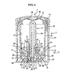
Fig. 4 is a sectional view illustrating a container for a viscous cosmetic according toEmbodiment 2 of the invention. -
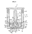
Fig. 5 is a sectional view illustrating a container for a viscous cosmetic according toEmbodiment 3 of the invention. -
- 1: CYLINDRICAL RECEIVING BODY
- 2: LID BODY
- 3: ROTATION BODY
- 4: SCREW SHAFT
- 5: SCREW THREAD CONNECTION SECTION
- 6: PACKING PRESSER
- 7: ANNULAR PACKING
- 9: INNER LID
- 12: INNER TRAY
- 27: FLAT SECTION
- 47: UPPER SECTION
- 48: LOWER SECTION
- 50: LOWER SURFACE
- 52: UPPER SURFACE
-
Embodiment 1 of the invention will be described with reference toFigs. 1 to 3 .Reference Numeral 1 denotes a cylindrical receiving body for receiving a viscous cosmetic therein. Aninner lid 9 is fixed to the upper end of thecylindrical receiving body 1. At the upper part of theinner lid 9, alid body 2 for blocking communication between the inside of thecylindrical receiving body 1 and the outside air is detachably connected to thecylindrical receiving body 1. Acylindrical rotation body 3 is connected to the lower end side of thecylindrical receiving body 1 in a rotatable manner about thecylindrical receiving body 1, and ascrew shaft 4 is fixed not to be rotated in an axial direction of thecylindrical receiving body 1 and is placed in thecylindrical receiving body 1 at the center of therotation body 3. Aninner tray 12 is installed on thescrew shaft 4 by means of screw thread, and aannular packing 7 is placed in intimate contact with alower surface 50 on a screwthread connection section 5 of theinner tray 12 through apacking presser 6. -
Embodiment 1 will be described in more detail. Thecylindrical receiving body 1 is made of PP and has a cylindrical shape. As shown inFig. 2 , an innerperipheral wall 8 and an outerperipheral wall 10 are provided at a predetermined distance, and the upper end of the innerperipheral wall 8 and the upper end of the outerperipheral wall 10 are continued to each other. The innerperipheral wall 8 has a length in the axial direction larger than a length of the outerperipheral wall 10 in the axial direction, and has abottom wall 11 having anopening section 19 formed at the center thereof, at the lower end of the innerperipheral wall 8. Ascrew groove 28 for screw thread connection to thelid body 2 is formed at the upper end of the outerperipheral wall 10, and alower end section 13 for connecting the upper end of therotation body 3 is formed in the inner peripheral surface of the lower end. An annular protrudingsection 14 for connecting theinner lid 9 is formed at the upper end of thecylindrical receiving body 1 formed as described above. - As shown in
Fig. 3 , a cylindrical and sectionalU-shaped rotation body 3 is connected to the lower end of thecylindrical receiving body 1. Therotation body 3 is made of PP and has aperipheral wall 15 and abottom plate 16, as shown inFig. 2 . An outer diameter of theperipheral wall 15 is substantially equal to the outerperipheral wall 10 of thecylindrical receiving body 1. Anupper end section 17 capable of being fitted to thelower end section 13 of thecylindrical receiving body 1 is provided at the upper end of theperipheral wall 15 in a peripheral direction. A cross-shapedfitting protruding section 18 for installing thescrew shaft 4 in a non-rotatable manner is formed at the center of thebottom plate 16 of therotation body 3, and anannular wall 20 is formed at the outer periphery of the fitting protrudingsection 18. As shown inFig. 1 , an engagement recessedsection 21 is formed on the inner peripheral surface of theannular wall 20 in the peripheral direction. A plurality ofribs 22 protruding in the axial direction are provided on the inner peripheral surface of therotation body 3 at a predetermined distance. - The inner
peripheral wall 8 of thecylindrical receiving body 1 is inserted into therotation body 3 formed as described above, and theupper end section 17 of therotation body 3 is allowed to come in intimate contact with thelower end section 13 of thecylindrical receiving body 1, thereby installing therotation body 3 at the lower end of thecylindrical receiving body 1. Therotation body 3 is installed at thecylindrical receiving body 1 as described above. Accordingly, as shown inFig. 1 , the lower surface of thebottom wall 11 of thecylindrical receiving body 1 comes in intimate contact with the upper surface of thebottom plate 16 of therotation body 3, theannular wall 20 and the fitting protrudingsection 18 provided on thebottom plate 16 of therotation body 3 are placed in theopening section 19 of thebottom wall 11 of thecylindrical receiving body 1. In this case, as shown inFig. 1 , since therib 22 protruding in therotation body 3 comes in intimate contact with the surface of theinner wall 8 of thecylindrical receiving body 1, it is possible to stably place theinner wall 8 of thecylindrical receiving body 1 in therotation body 3. For this reason, it is possible to stably and smoothly rotate therotation body 3 installed at the receivingbody 1. - The
screw shaft 4 made of PP shown inFig. 1 is connected to the center of thebottom plate 16 of therotation body 3 installed at thecylindrical receiving body 1. That is, anannular connection section 23 capable of being inserted into theannular wall 20 of therotation body 3 is provided at the lower end of thescrew shaft 4, and a cross-shaped fitting recessedsection 24 capable of being fitted to the fitting protrudingsection 18 of therotation body 3 is provided in a recessed shape from the lower end of theconnection section 23 inward. An annularengagement protruding section 25 capable of engaging with the engagement recessedsection 21 provided at the inner periphery of theannular wall 20 of therotation body 3 is formed on the outer peripheral surface of theconnection section 23. - The
engagement protruding section 25 of theconnection section 23 is engaged with the engagement recessedsection 21 of theannular wall 20 with the fitting protrudingsection 18 of therotation body 3 inserted to the fitting recessedsection 24 of thescrew shaft 4, and thus it is possible to connect and fix thescrew shaft 4 to therotation body 3 in a non-rotatable manner. For this reason, when therotation body 3 is rotated, thescrew shaft 4 is also rotated by the rotation of therotation body 3. As shown inFig. 2 , thescrew shaft 4 is continuously provided with a screw groove formedsection 26 on the outer peripheral surface thereof and aflat section 27 having no screw groove from the upper end and the lower end, in the axial direction. Theflat section 27 is provided at two opposite parts of thescrew shaft 4, and has a substantially oval shape in the sectional view. - As shown in
Fig. 3 , thescrew shaft 4 installed at therotation body 3 is connected to a substantially cylindricalinner tray 12 by means of screw thread. As shown inFig. 2 , theinner tray 12 is made of HDPE, and has an annularinner wall 31 formed on the lower surface of a plate-shapedupper wall 30. An annularouter wall 32 is provided at the outer periphery of theupper wall 30 at a predetermined distance from theupper wall 30. As shown inFig. 1 , theouter wall 32 has a shape protruding both widthwiseside sections 55 outward by slightly bending the widthwise center thereof inward. As shown inFig. 2 , acircular hole section 33 is formed at the center of theupper wall 30, and an annular screwthread connection section 5 having a screw groove capable of being connected to thescrew shaft 4 by means of screw thread is formed in the inner periphery of thehole section 33. - As shown in
Fig. 1 , theannular packing 7 is placed in intimate contact with the lower end of the screwthread connection section 5. Theannular packing 7 is made of NBR having flexibility and elasticity, and has a substantially oval shape as shown inFig. 2 . A through-hole 35 is formed at the center thereof in a substantially oval shape. When thescrew shaft 4 is inserted into and passed through the through-hole 35, an innerperipheral end surface 36 of the through-hole 35 is formed in intimate contact with theflat section 27 of thescrew shaft 4. As shown inFig. 1 , theannular packing 7 is connected to and placed in theinner tray 12 through the sectionalU-shaped packing presser 6. - That is, the
packing presser 6 has anannular connection wall 38 and aflat bottom section 40 as shown inFig. 2 , and a substantiallyoval insertion hole 41 capable of inserting and passing thescrew shaft 4 is formed at the center of thebottom section 40. When thescrew shaft 4 is inserted and passed through theinsertion hole 41, the outer peripheral surface of thescrew shaft 4 comes in contact with the inner peripheral end surface of theinsertion hole 41. Theannular packing 7 formed as described above is capable of being received in thepacking presser 6. When theannular packing 7 is received in thepacking presser 6, the outer peripheral surface of theannular packing 7 comes in intimate contact with the inner peripheral surface of theconnection wall 38 of thepacking presser 6. - The
packing presser 6 formed as described above is connected to the inside of theinner wall 31 of theinner tray 12, and an annular protrudingsection 44 capable of being fitted to anannular receiving section 43 formed on the inner peripheral surface of theinner wall 31 of theinner tray 12 is provided on the outer peripheral surface of theconnection wall 38 of thepacking presser 6. The annular protrudingsection 44 is fitted to the fitting receiving section of theinner wall 31 of theinner tray 12 and thepacking presser 6 is placed in theinner wall 31 of theinner tray 12, thereby connecting thepacking presser 6 to theinner tray 12 in a rotatable manner and in a non-detachable manner. - When the
packing presser 6 receiving theannular packing 7 as described above is connected to theinner tray 12, theannular packing 7 is elastically deformed and theupper end section 37 thereof comes in intimate contact with thelower surface 50 of the screwthread connection section 5 of theinner tray 12. As described above, since the inner peripheral surface of the through-hole 35 of theannular packing 7 comes in intimate contact with theflat section 27 of thescrew shaft 4, theannular packing 7 comes in intimate contact with theinner tray 12 and thescrew shaft 4 on the inner peripheral end surfaces of the through-hole 35 and theupper end surface 37. Accordingly, it is possible to air-tightly seal off theupper section 47 and thelower section 48 of theinner tray 12 at the screwthread connection section 5 between theinner tray 12 and thescrew thread 4. As described above, since theannular packing 7 is placed in intimate contact with theinner tray 12 through thepacking presser 6 to connect and fix thepacking presser 6 to theinner tray 12, theannular packing 7 is not detached from theinner tray 12 and it is possible to securely keep the intimate contact between the packing 7 and theinner tray 12. - The plate-shaped
inner lid 9 is connected and fixed to the annular protrudingsection 14 provided at the upper end of thecylindrical receiving body 1. Theinner lid 9 is provided with four division holes 46 for ejecting a viscous cosmetic received in the receivingbody 1. As shown inFig. 1 , thelid body 2, the lower end of which is detachably connected to the outerperipheral wall 10 of thecylindrical receiving body 1, is placed at the upper part of theinner lid 9, and it is possible to block communication between the inside of thecylindrical receiving body 1 and the outside air at the keeping time by the connection of thelid body 2. At the using time, thelid body 2 is separated from thecylindrical receiving body 1. - In the container for a viscous cosmetic according to the embodiment configured as described above, first, the
upper section 47 of theinner tray 12 in thecylindrical receiving body 1 is filled with a viscous cosmetic. In the present embodiment and the following embodiments, a liquid cream is used as the viscous cosmetic. In the other embodiments, a cleansing cream, a cream foundation, a lip gloss, a base for a lipstick, a liquid lipstick, and the other viscous cosmetic may be used. In such a state, therotation body 3 is rotated in one direction while keeping thecylindrical receiving body 1, thereby rotating thescrew shaft 4 installed at therotation body 3 in the same direction by the rotation of therotation body 3. - The
inner tray 12 connected to thescrew shaft 4 by means of screw thread is moved up along thescrew shaft 4 by the rotation of thescrew shaft 4. In this case, theouter wall 32 of theinner tray 12 is tightened toward the screwthread connection section 5 by the innerperipheral wall 8 of the receivingbody 1 by controlling the outer diameter of theinner tray 12. Accordingly, the both widthwiseside sections 55 protruding outward in theouter wall 32 of theinner tray 12 come in intimate contact with the inner peripheral surface of the innerperipheral wall 8 of thecylindrical receiving body 1 continuously in the peripheral direction. As described above, since theouter wall 32 of theinner tray 12 is tightened by the inner peripheral surface of the innerperipheral wall 8 of the receivingbody 1, a torque on the screwthread connection section 5 side of theinner tray 12 can be larger than a torque on theouter wall 32 side. - Values of the torques were actually measured by a torque meter (manufactured by IMADA Co., Ltd). As a result, when a force representing a tightening degree to the
inner tray 12 is 23.5 N, the torque on the screwthread connection section 5 side was 15.5 Ncm and the torque on theouter wall 32 side was 56.7 Ncm. As described above, theouter wall 32 of theinner tray 12 is tightened toward the screwthread connection section 5 by the innerperipheral wall 8 of thecylindrical receiving body 1, and the torque on theouter wall 32 is larger than the torque on the screwthread connection section 5 side of theinner tray 12. In this state, when thescrew shaft 4 is rotated through therotation body 3, theinner tray 12 installed at thescrew shaft 4 is not rotated in the receivingbody 1 and is slidable in the axial direction along thescrew shaft 4. Accordingly, it is possible to smoothly slide theinner tray 12 in the vertical direction, in the state where theouter wall 32 of theinner tray 12 and the innerperipheral wall 8 of thecylindrical receiving body 1 come in intimate contact with each other through out the whole periphery, by rotating therotation body 3. - As described above, the
inner tray 12 is slid in the vertical direction, thereby also sliding thepacking presser 6 connected to theinner tray 12 and theannular packing 7 received in thepacking presser 6 along thescrew shaft 4 at the same time. When therotation body 3 is rotated, theinner tray 12 is not rotated and is slid in the vertical direction. However, since thepacking presser 6 and theannular packing 7 are rotatably connected to theinner tray 12, they are rotated by the rotation of thescrew shaft 4. - In this case, since the
upper end surface 37 of theannular packing 7 comes in intimate contact with thelower surface 50 of theinner wall 31 of theinner tray 12 and the innerperipheral end surface 36 of the through-hole 35 comes in intimate contact with theflat section 27 of thescrew shaft 4, it is possible to slide theinner tray 12 while air-tightly sealing off theupper section 47 and thelower section 48 of theinner tray 12, at the screwthread connection section 5 of theinner tray 12. Since theouter wall 32 of theinner tray 12 and the innerperipheral wall 8 of thecylindrical receiving body 1 come in intimate contact with each other through out the whole periphery as described above, it is possible to slide theinner tray 12 while air-tightly sealing off theupper section 47 and thelower section 48, on theouter wall 32 side of theinner tray 12. Accordingly, it is possible to air-tightly seal off theupper section 47 and thelower section 48 of theinner tray 12 on both sides of theouter wall 32 side and the screwthread connection section 5 side of theinner tray 12, and thus it is possible to securely prevent a viscous cosmetic on theupper section 47 side of theinner tray 12 from leaking out to thelower section 48. - In such a state, the
inner tray 12 is moved up by rotating therotation body 3 in one direction, thereby ejecting the viscous cosmetic received on theupper section 47 of theinner tray 12 from the division holes 46 of theinner lid 9. At this time, a user can eject only a necessary amount of the viscous cosmetic from the division holes 46 by controlling the rotation of therotation body 3. At the last finishing time of the using, since theupper wall 30 of theinner tray 12 comes in intimate contact with the inner surface of theinner lid 9, it is possible to minimize the remaining amount of the viscous cosmetic. Accordingly, it is possible to economically use the viscous cosmetic without waste. - When the
inner lid 9 is placed at the upper end of thecylindrical receiving body 1 as described above, a user scoops up and uses only the viscous cosmetic ejected from the division holes 46 to the surface of theinner lid 9. Accordingly, it is not necessary to insert a finger in thecylindrical receiving body 1, and thus it is possible to prevent pollution of the viscous cosmetic received in thecylindrical receiving body 1. Therefore, it is possible to sanitarily use the viscous cosmetic. - In the present embodiment and the following
Embodiment 2 andEmbodiment 3, therotation body 3 and thescrew shaft 4 are formed separately from each other. However, in the other embodiments, therotation body 3 and thescrew shaft 4 can be formed integrally with each other. - In
Embodiment 1, thepacking presser 6 receiving theannular packing 7 is fixed to thelower surface 50 side of theinner tray 12. However, inEmbodiment 2 of the invention, as shown inFig. 4 , the annularinner wall 31 protrudes on the upper surface of thebottom side wall 54 of theinner tray 12, the annularouter wall 32 is provided at the upper surface periphery of thebottom side wall 54, thepacking presser 6 receiving theannular packing 7 is connected and fixed to theinner wall 31 of theinner tray 12, and the lower end surface 53 of theannular packing 7 is placed in intimate contact with theupper surface 52 of the screwthread connection section 5 of theinner tray 12. - The through-
hole 35 of theannular packing 7 is formed substantially in the same size as that of theinsertion hole 4 of thepacking presser 6. Accordingly, when thepacking presser 6 receiving theannular packing 7 is installed at theinner tray 12, the wholeupper end surface 37 of theannular packing 7 is covered with thebottom section 40 of thepacking presser 6. Accordingly, when a viscous cosmetic is received in thecylindrical receiving body 1, the viscous cosmetic comes in contact with thepacking presser 6 installed at theinner tray 12, but hardly comes in contact with theupper end surface 37 of theannular packing 7 received in thepacking presser 6. For this reason, it is possible to avoid a problem such as swelling of theannular packing 7 caused by the contact of the viscous cosmetic. - In
Embodiments annular packing 7 made of NBR is placed in intimate contact with theupper surface 52 or thelower surface 50 of theinner tray 12 through thepacking presser 6. However, inEmbodiment 3 of the invention, as shown inFig. 5 , theannular packing 7 made of LDPE comes directly in intimate contact with theinner tray 12 without using thepacking presser 6. -
Embodiment 3 will be described in more detail. Theannular packing 7 according to the present embodiment is formed in a cylindrical shape, the through-hole 35 is formed at the center of theannular packing 7, and the innerperipheral end surface 36 of the through-hole 35 is placed in intimate contact with theflat section 27 of thescrew shaft 4. As shown inFig. 5 , theannular packing 7 is connected to the inside of theinner wall 31 protruding on the lower surface of theupper wall 30 of theinner tray 12, and an annular protrudingsection 51 capable of engaging with theannular receiving section 43 formed on theinner wall 31 is provided on the outer peripheral surface thereof. - The
annular packing 7 formed as described above is installed in theinner wall 31 of theinner tray 12 with theannular receiving section 43 and the annular protrudingsection 51 engaging with each other, and thus it is possible to rotatably connect theannular packing 7 to theinner tray 12. Accordingly, theinner tray 12 is not rotated and is moved in the vertical direction by rotating thescrew shaft 4, but theannular packing 7 is slid while rotating together with thescrew shaft 4 as being connected to theinner tray 12. - Since the
upper end surface 37 of theannular packing 7 is fixed to thelower surface 50 of the screwthread connection section 5 of theinner tray 12 and the inner peripheral surface of the through-hole 35 comes in intimate contact with theflat section 27 of thescrew shaft 4 as described above, it is possible to air-tightly seal off theupper section 47 and thelower section 48 in the screwthread connection section 5 of theinner tray 12. As described above, theannular packing 7 is directly connected to theinner tray 12 without using thepacking presser 6, thereby reducing the number of components. Therefore, it is possible to obtain inexpensive products. - In
Embodiments inner lid 9 is provided at the upper end of thecylindrical receiving body 1. However, inEmbodiment 3, theinner lid 9 is not provided. Accordingly, the number of components is reduced, and thus it is possible to produce inexpensive products. In addition, it is possible to check the remaining amount of the viscous cosmetic received in thecylindrical receiving body 1 with the naked eye, and it is possible to keep the surface of the viscous cosmetic constantly at a regular level by moving out theinner tray 12 according to reduction of the viscous cosmetic.
Claims (8)
- A container for a viscous cosmetic comprising:a cylindrical receiving body (1) that receives a viscous cosmetic therein;a lid body (2) that is detachably connected to an upper end of the cylindrical receiving body (1) and air-tightly seals off communication between the inside of the cylindrical receiving body (1) and the outside air;a rotation body (3) that is connected and placed at a lower end of the cylindrical receiving body (1) in a slidable manner;a screw shaft (4) that is placed at the center of the rotation body (3) coaxially with a shaft direction of the cylindrical receiving body (1) and is inserted into the cylindrical receiving body (1);an inner tray (12) that is connected to an outer periphery of the screw shaft (4) by means of screw thread and, an outer periphery of which is placed so as to be slidable on and in intimate contact with an inner surface of the cylindrical receiving body (1); andwherein the inner tray (12) is installed and is tightened toward the screw shaft (4) with the outer periphery thereof placed in intimate contact with the outer periphery, a torque on the outer peripheral side placed in intimate contact with the cylindrical receiving body (1) is larger than a torque on the screw thread section (5) side of the inner tray (12) with the inner peripheral surface placed in intimate contact with the outer periphery of the inner tray (12), the inner tray (12) is slidable in an axial direction with the inner tray (12) hardly rotated in the cylindrical receiving body (1), the screw shaft (4) has a flat section having no screw groove in the axial direction,characterised in that the container comprises an annular packing (7) that is placed in intimate contact with the surface on the screw thread connection section (5) side of the inner tray (12), an inner peripheral end of which is placed so as to be in intimate contact with the outer periphery of the screw shaft (4), and is slidable along the screw shaft (4) by sliding the inner tray (12), and the upper section and the lower section are air-tightly sealed off by allowing the flat section and the inner peripheral end surface of the annular packing (7) be in intimate contact with each other.
- The container for a viscous cosmetic according to claim 1, wherein the annular packing (7) is placed in a packing presser (6) having a sectional U shape, and the packing presser (6) is placed in intimate contact with the inner tray (12) by fixing the packing presser (6) to the inner tray (12) in a slidable manner.
- The container for a viscous cosmetic according to claim 1, wherein the annular packing (7) is placed in intimate contact with the inner tray (12) in a slidable manner.
- The container for a viscous cosmetic according to any one of claims 1 to 3, wherein the annular packing (7) is placed on the upper surface on the screw thread connection section (5) side of the inner tray (12).
- The container for a viscous cosmetic according to any one of claims 1 to 3, wherein the annular packing (7) is on the lower surface on the screw thread connection section (5) side of the inner tray (12).
- The container for a viscous cosmetic according to claim 1, wherein the screw shaft (4) is formed integrally with the rotation body (3).
- The container for a viscous cosmetic according to claim 1, wherein the screw shaft (4) is formed separately from the rotation body (3).
- The container for a viscous cosmetic according to claim 1, wherein the cylindrical receiving body (1) is provided with an inner lid (9) having one or more division holes, at the upper end thereof.
Applications Claiming Priority (2)
| Application Number | Priority Date | Filing Date | Title |
|---|---|---|---|
| JP2006219850A JP4897388B2 (en) | 2006-08-11 | 2006-08-11 | Viscous cosmetic container |
| PCT/JP2007/065191 WO2008018367A1 (en) | 2006-08-11 | 2007-08-02 | Container for viscous cosmetic |
Publications (3)
| Publication Number | Publication Date |
|---|---|
| EP2052640A1 EP2052640A1 (en) | 2009-04-29 |
| EP2052640A4 EP2052640A4 (en) | 2014-06-04 |
| EP2052640B1 true EP2052640B1 (en) | 2015-02-25 |
Family
ID=39032899
Family Applications (1)
| Application Number | Title | Priority Date | Filing Date |
|---|---|---|---|
| EP07791865.4A Not-in-force EP2052640B1 (en) | 2006-08-11 | 2007-08-02 | Container for viscous cosmetic |
Country Status (6)
| Country | Link |
|---|---|
| US (1) | US8297867B2 (en) |
| EP (1) | EP2052640B1 (en) |
| JP (1) | JP4897388B2 (en) |
| KR (1) | KR101377732B1 (en) |
| CN (1) | CN101472500B (en) |
| WO (1) | WO2008018367A1 (en) |
Cited By (1)
| Publication number | Priority date | Publication date | Assignee | Title |
|---|---|---|---|---|
| WO2020249816A2 (en) | 2019-06-13 | 2020-12-17 | Rpc Bramlage Gmbh | Device for dispensing a compound |
Families Citing this family (26)
| Publication number | Priority date | Publication date | Assignee | Title |
|---|---|---|---|---|
| JP4931000B2 (en) * | 2007-02-28 | 2012-05-16 | 株式会社吉野工業所 | A container equipped with a raising mechanism |
| US8961048B2 (en) | 2008-12-23 | 2015-02-24 | Conopco, Inc. | Dispenser for a composition in stick form |
| US8690467B2 (en) | 2008-12-23 | 2014-04-08 | Conopco Inc. | Dispenser |
| MX2011006848A (en) | 2008-12-23 | 2011-09-08 | Unilever Nv | DISPENSER. |
| KR101453632B1 (en) * | 2009-12-23 | 2014-10-22 | 콜게이트-파아므올리브캄파니 | Oral care system |
| JP5611703B2 (en) * | 2010-07-30 | 2014-10-22 | 株式会社吉野工業所 | Dispenser |
| US8627987B2 (en) * | 2010-08-25 | 2014-01-14 | Wisys Technology Foundation | Container with elevating inner wall |
| JP5679428B2 (en) * | 2010-12-24 | 2015-03-04 | 株式会社吉野工業所 | A container equipped with a raising mechanism |
| JP5679429B2 (en) * | 2010-12-27 | 2015-03-04 | 株式会社吉野工業所 | A container equipped with a raising mechanism |
| KR101293804B1 (en) | 2011-07-05 | 2013-08-06 | 황재광 | Fixed quantity dispensing cream container |
| CN103662301A (en) * | 2013-11-22 | 2014-03-26 | 无锡莱吉特信息科技有限公司 | Particulate matter storage device |
| WO2016036761A1 (en) * | 2014-09-02 | 2016-03-10 | HCT Group Holdings Limited | Container with dispensing tip |
| US10196196B2 (en) * | 2014-09-11 | 2019-02-05 | Vcxt, Llc | Watertight liquid dispenser with syringe-like functions |
| WO2016061400A1 (en) * | 2014-10-15 | 2016-04-21 | Custom Rx Tda, Llc | Metering dispenser for flowable compositions |
| KR101575034B1 (en) | 2015-03-19 | 2015-12-07 | 김상선 | Airtight liquid foundation container |
| EP3372980A4 (en) * | 2015-11-05 | 2019-07-17 | Shiseido Company Ltd. | Stratum corneum collection tool and stratum corneum collection/detection kit |
| US10506863B2 (en) * | 2015-11-05 | 2019-12-17 | Tessy Plastics Corporation | Toiletry applicator |
| JP6776008B2 (en) * | 2016-05-31 | 2020-10-28 | 株式会社吉野工業所 | Rotating feeding container for liquid contents |
| US10625927B2 (en) * | 2016-09-23 | 2020-04-21 | The Procter & Gamble Company | Consumer product package |
| US11382400B2 (en) | 2018-08-10 | 2022-07-12 | Go Products Co. | Material applicator |
| WO2020260586A1 (en) * | 2019-06-28 | 2020-12-30 | Rpc Bramlage Gmbh | Device for discharging a substance |
| CN210592893U (en) * | 2019-08-30 | 2020-05-22 | 余姚市彩昀化妆品包装有限公司 | A new type of rotary bottle with replaceable inner liner |
| CN215603747U (en) * | 2021-06-10 | 2022-01-25 | 余姚市彩昀化妆品包装有限公司 | Replaceable container |
| US12622500B2 (en) | 2023-04-20 | 2026-05-12 | Lg H&H Co., Ltd. | Cosmetic vessel |
| KR102892803B1 (en) | 2024-04-08 | 2025-11-28 | 주식회사 씨티케이 | Cosmetics container having a structure that doubles the lifting operation distance |
| KR102892801B1 (en) | 2024-04-08 | 2025-11-28 | 주식회사 씨티케이 | Cosmetics container having a structure that doubles the lifting operation distance |
Family Cites Families (23)
| Publication number | Priority date | Publication date | Assignee | Title |
|---|---|---|---|---|
| US1458281A (en) * | 1922-04-03 | 1923-06-12 | Howard E Everett | Dauber |
| US1728298A (en) * | 1927-12-07 | 1929-09-17 | Marion Fredenberg | Dispensing container |
| FR969474A (en) * | 1947-06-23 | 1950-12-20 | Device serving as a container, ejector and dispenser for pasty, fatty or semi-liquid materials and the like | |
| US2738905A (en) * | 1950-11-10 | 1956-03-20 | Carl E Olson | Paste or like dispenser |
| JPS5425246Y2 (en) * | 1974-10-14 | 1979-08-23 | ||
| JPS5151943A (en) * | 1974-11-01 | 1976-05-07 | Ricoh Kk | Hodenkirokuzairyo oyobisono seizoho |
| US3907441A (en) * | 1974-12-30 | 1975-09-23 | Eyelet Specialty Co | Sealed container for dispensing a volatile product |
| GB2103293B (en) | 1981-07-21 | 1985-03-06 | Oreal | Dosage dispenser device |
| FR2509980A1 (en) * | 1981-07-21 | 1983-01-28 | Oreal | Distributor doser for viscous materials - includes rigid container with sliding piston traversed by longitudinal rack and control pawl |
| US4521127A (en) * | 1982-11-30 | 1985-06-04 | Gibson Associates, Inc. | Sealed propulsion mechanism for a stick-deodorant or the like container |
| JP2534943Y2 (en) * | 1990-10-31 | 1997-05-07 | 大和製罐株式会社 | Machined container |
| BR9401921A (en) * | 1993-07-08 | 1995-03-07 | Mark Ind Inc | Lipstick and similar retainer |
| CN2176670Y (en) * | 1993-11-30 | 1994-09-14 | 天津竹内装璜有限公司 | Lipstick casing |
| US5547302A (en) * | 1994-07-29 | 1996-08-20 | The Procter & Gamble Company | Twist-up product dispenser having conformable apertured applicator surface |
| FR2727608B1 (en) | 1994-12-06 | 1997-01-10 | Oreal | DISPENSER FOR A LIQUID CONSISTENCY PRODUCT WITH PASTE |
| US5733058A (en) * | 1996-09-16 | 1998-03-31 | Blistex Inc. | Dispensing container for a compact product |
| GB2354999B (en) * | 1999-10-08 | 2003-06-11 | Unilever Plc | Dispenser |
| JP3735100B2 (en) * | 2002-07-09 | 2006-01-11 | 株式会社トキワ | Mobile body feeding device |
| JP3764892B2 (en) | 2002-07-09 | 2006-04-12 | 株式会社トキワ | Mobile body feeding device, ratchet set, and cylindrical body |
| EP1468626B1 (en) * | 2003-04-15 | 2007-04-18 | Rexam Dispensing Systems S.A.S.U. | Rotary dispenser for liquid cosmetics |
| JP2005168745A (en) | 2003-12-10 | 2005-06-30 | Shiseido Co Ltd | Viscous cosmetic material container |
| KR200362376Y1 (en) * | 2004-06-25 | 2004-09-23 | 강성일 | A structure of casmetic case which is possible for discharge standard capacity of high viscosity cosmetic |
| EP2123188B8 (en) * | 2007-03-15 | 2013-03-06 | Shiseido Company, Ltd. | Propelling container |
-
2006
- 2006-08-11 JP JP2006219850A patent/JP4897388B2/en active Active
-
2007
- 2007-08-02 WO PCT/JP2007/065191 patent/WO2008018367A1/en not_active Ceased
- 2007-08-02 EP EP07791865.4A patent/EP2052640B1/en not_active Not-in-force
- 2007-08-02 CN CN2007800230961A patent/CN101472500B/en not_active Expired - Fee Related
- 2007-08-02 US US12/310,088 patent/US8297867B2/en not_active Expired - Fee Related
-
2008
- 2008-10-15 KR KR1020087025155A patent/KR101377732B1/en not_active Expired - Fee Related
Cited By (2)
| Publication number | Priority date | Publication date | Assignee | Title |
|---|---|---|---|---|
| WO2020249816A2 (en) | 2019-06-13 | 2020-12-17 | Rpc Bramlage Gmbh | Device for dispensing a compound |
| US11950681B2 (en) | 2019-06-13 | 2024-04-09 | Rpc Bramlage Gmbh | Device for dispensing a compound |
Also Published As
| Publication number | Publication date |
|---|---|
| WO2008018367A1 (en) | 2008-02-14 |
| US20090324321A1 (en) | 2009-12-31 |
| US8297867B2 (en) | 2012-10-30 |
| CN101472500B (en) | 2011-04-06 |
| JP2008043415A (en) | 2008-02-28 |
| HK1130164A1 (en) | 2009-12-24 |
| EP2052640A1 (en) | 2009-04-29 |
| JP4897388B2 (en) | 2012-03-14 |
| CN101472500A (en) | 2009-07-01 |
| KR20090036541A (en) | 2009-04-14 |
| KR101377732B1 (en) | 2014-03-21 |
| EP2052640A4 (en) | 2014-06-04 |
Similar Documents
| Publication | Publication Date | Title |
|---|---|---|
| US8297867B2 (en) | Container for viscous cosmetic | |
| EP1829797B1 (en) | Ejecting container | |
| EP2123188A1 (en) | Propelling container | |
| US8448797B2 (en) | Bottle containing two kinds of materials separately in two spaces | |
| CA2720098C (en) | Seal indication mechanism for containers | |
| US9797511B2 (en) | Piston and cartridge arrangement having said piston | |
| EP0319135A2 (en) | Device for dispensing multiple components | |
| RU2010115513A (en) | DEVICE FOR CONTAINING FLUID SUBSTANCES UNDER SEALING CONDITIONS AND FOR THE DISCLOSURE OF THEM | |
| WO2009027981A3 (en) | Multi-compartment container system | |
| JP7398957B2 (en) | Product dispensing device with refills or modules | |
| US20050057637A1 (en) | Seal for a two-component cartridge | |
| US6978981B2 (en) | Taps for controlling liquid flow | |
| CA2553550A1 (en) | Beverage dispenser | |
| AU1789600A (en) | Improvements in or relating to fluid containers | |
| US20040091303A1 (en) | Dispensers for liquids | |
| CN101014263A (en) | Cosmetic container structure for discharging certain amount of highly viscous cosmetic | |
| AU2002253428A1 (en) | Taps for controlling liquid flow | |
| US20180228267A1 (en) | Retractable dispenser and application head | |
| CN211996915U (en) | Rotary control liquid outlet cover | |
| CN210213461U (en) | Hooking and adjusting device | |
| CN110304349B (en) | Hook adjusting device | |
| JP7617626B2 (en) | Faucet and dispensing device | |
| US20170224086A1 (en) | Retractable dispenser and application head | |
| HK1130164B (en) | Container for viscous cosmetic | |
| WO2025000266A1 (en) | Rechargeable cosmetic container |
Legal Events
| Date | Code | Title | Description |
|---|---|---|---|
| PUAI | Public reference made under article 153(3) epc to a published international application that has entered the european phase |
Free format text: ORIGINAL CODE: 0009012 |
|
| 17P | Request for examination filed |
Effective date: 20090105 |
|
| AK | Designated contracting states |
Kind code of ref document: A1 Designated state(s): AT BE BG CH CY CZ DE DK EE ES FI FR GB GR HU IE IS IT LI LT LU LV MC MT NL PL PT RO SE SI SK TR |
|
| AX | Request for extension of the european patent |
Extension state: AL BA HR MK RS |
|
| DAX | Request for extension of the european patent (deleted) | ||
| A4 | Supplementary search report drawn up and despatched |
Effective date: 20140508 |
|
| RIC1 | Information provided on ipc code assigned before grant |
Ipc: B65D 83/00 20060101ALI20140430BHEP Ipc: A45D 40/00 20060101ALI20140430BHEP Ipc: A45D 34/00 20060101AFI20140430BHEP |
|
| RIC1 | Information provided on ipc code assigned before grant |
Ipc: B65D 83/00 20060101ALI20140904BHEP Ipc: A45D 40/04 20060101ALI20140904BHEP Ipc: A45D 34/00 20060101AFI20140904BHEP Ipc: A45D 40/00 20060101ALI20140904BHEP |
|
| GRAP | Despatch of communication of intention to grant a patent |
Free format text: ORIGINAL CODE: EPIDOSNIGR1 |
|
| INTG | Intention to grant announced |
Effective date: 20141022 |
|
| GRAS | Grant fee paid |
Free format text: ORIGINAL CODE: EPIDOSNIGR3 |
|
| GRAA | (expected) grant |
Free format text: ORIGINAL CODE: 0009210 |
|
| RIN1 | Information on inventor provided before grant (corrected) |
Inventor name: MIZUSHIMA, HIROSHI C/O YOSHINO KOGYOSHO CO., LTD. Inventor name: KISHI, TAKAO C/O YOSHINO KOGYOSHO CO., LTD. Inventor name: NASU, MIEKO C/O SHISEIDO RESEARCH CENTER(SHIN-YOKO |
|
| AK | Designated contracting states |
Kind code of ref document: B1 Designated state(s): AT BE BG CH CY CZ DE DK EE ES FI FR GB GR HU IE IS IT LI LT LU LV MC MT NL PL PT RO SE SI SK TR |
|
| REG | Reference to a national code |
Ref country code: GB Ref legal event code: FG4D |
|
| REG | Reference to a national code |
Ref country code: CH Ref legal event code: EP |
|
| REG | Reference to a national code |
Ref country code: IE Ref legal event code: FG4D |
|
| REG | Reference to a national code |
Ref country code: DE Ref legal event code: R096 Ref document number: 602007040362 Country of ref document: DE Effective date: 20150409 |
|
| REG | Reference to a national code |
Ref country code: AT Ref legal event code: REF Ref document number: 711158 Country of ref document: AT Kind code of ref document: T Effective date: 20150415 |
|
| REG | Reference to a national code |
Ref country code: NL Ref legal event code: VDEP Effective date: 20150225 |
|
| REG | Reference to a national code |
Ref country code: AT Ref legal event code: MK05 Ref document number: 711158 Country of ref document: AT Kind code of ref document: T Effective date: 20150225 |
|
| REG | Reference to a national code |
Ref country code: LT Ref legal event code: MG4D |
|
| PG25 | Lapsed in a contracting state [announced via postgrant information from national office to epo] |
Ref country code: LT Free format text: LAPSE BECAUSE OF FAILURE TO SUBMIT A TRANSLATION OF THE DESCRIPTION OR TO PAY THE FEE WITHIN THE PRESCRIBED TIME-LIMIT Effective date: 20150225 Ref country code: ES Free format text: LAPSE BECAUSE OF FAILURE TO SUBMIT A TRANSLATION OF THE DESCRIPTION OR TO PAY THE FEE WITHIN THE PRESCRIBED TIME-LIMIT Effective date: 20150225 Ref country code: FI Free format text: LAPSE BECAUSE OF FAILURE TO SUBMIT A TRANSLATION OF THE DESCRIPTION OR TO PAY THE FEE WITHIN THE PRESCRIBED TIME-LIMIT Effective date: 20150225 Ref country code: SE Free format text: LAPSE BECAUSE OF FAILURE TO SUBMIT A TRANSLATION OF THE DESCRIPTION OR TO PAY THE FEE WITHIN THE PRESCRIBED TIME-LIMIT Effective date: 20150225 |
|
| PG25 | Lapsed in a contracting state [announced via postgrant information from national office to epo] |
Ref country code: LV Free format text: LAPSE BECAUSE OF FAILURE TO SUBMIT A TRANSLATION OF THE DESCRIPTION OR TO PAY THE FEE WITHIN THE PRESCRIBED TIME-LIMIT Effective date: 20150225 Ref country code: GR Free format text: LAPSE BECAUSE OF FAILURE TO SUBMIT A TRANSLATION OF THE DESCRIPTION OR TO PAY THE FEE WITHIN THE PRESCRIBED TIME-LIMIT Effective date: 20150526 Ref country code: AT Free format text: LAPSE BECAUSE OF FAILURE TO SUBMIT A TRANSLATION OF THE DESCRIPTION OR TO PAY THE FEE WITHIN THE PRESCRIBED TIME-LIMIT Effective date: 20150225 Ref country code: IS Free format text: LAPSE BECAUSE OF FAILURE TO SUBMIT A TRANSLATION OF THE DESCRIPTION OR TO PAY THE FEE WITHIN THE PRESCRIBED TIME-LIMIT Effective date: 20150625 |
|
| PG25 | Lapsed in a contracting state [announced via postgrant information from national office to epo] |
Ref country code: NL Free format text: LAPSE BECAUSE OF FAILURE TO SUBMIT A TRANSLATION OF THE DESCRIPTION OR TO PAY THE FEE WITHIN THE PRESCRIBED TIME-LIMIT Effective date: 20150225 |
|
| PG25 | Lapsed in a contracting state [announced via postgrant information from national office to epo] |
Ref country code: DK Free format text: LAPSE BECAUSE OF FAILURE TO SUBMIT A TRANSLATION OF THE DESCRIPTION OR TO PAY THE FEE WITHIN THE PRESCRIBED TIME-LIMIT Effective date: 20150225 Ref country code: EE Free format text: LAPSE BECAUSE OF FAILURE TO SUBMIT A TRANSLATION OF THE DESCRIPTION OR TO PAY THE FEE WITHIN THE PRESCRIBED TIME-LIMIT Effective date: 20150225 Ref country code: SK Free format text: LAPSE BECAUSE OF FAILURE TO SUBMIT A TRANSLATION OF THE DESCRIPTION OR TO PAY THE FEE WITHIN THE PRESCRIBED TIME-LIMIT Effective date: 20150225 Ref country code: CZ Free format text: LAPSE BECAUSE OF FAILURE TO SUBMIT A TRANSLATION OF THE DESCRIPTION OR TO PAY THE FEE WITHIN THE PRESCRIBED TIME-LIMIT Effective date: 20150225 Ref country code: RO Free format text: LAPSE BECAUSE OF FAILURE TO SUBMIT A TRANSLATION OF THE DESCRIPTION OR TO PAY THE FEE WITHIN THE PRESCRIBED TIME-LIMIT Effective date: 20150225 |
|
| REG | Reference to a national code |
Ref country code: DE Ref legal event code: R097 Ref document number: 602007040362 Country of ref document: DE |
|
| PG25 | Lapsed in a contracting state [announced via postgrant information from national office to epo] |
Ref country code: PL Free format text: LAPSE BECAUSE OF FAILURE TO SUBMIT A TRANSLATION OF THE DESCRIPTION OR TO PAY THE FEE WITHIN THE PRESCRIBED TIME-LIMIT Effective date: 20150225 |
|
| PG25 | Lapsed in a contracting state [announced via postgrant information from national office to epo] |
Ref country code: IT Free format text: LAPSE BECAUSE OF FAILURE TO SUBMIT A TRANSLATION OF THE DESCRIPTION OR TO PAY THE FEE WITHIN THE PRESCRIBED TIME-LIMIT Effective date: 20150225 |
|
| PLBE | No opposition filed within time limit |
Free format text: ORIGINAL CODE: 0009261 |
|
| STAA | Information on the status of an ep patent application or granted ep patent |
Free format text: STATUS: NO OPPOSITION FILED WITHIN TIME LIMIT |
|
| 26N | No opposition filed |
Effective date: 20151126 |
|
| PG25 | Lapsed in a contracting state [announced via postgrant information from national office to epo] |
Ref country code: SI Free format text: LAPSE BECAUSE OF FAILURE TO SUBMIT A TRANSLATION OF THE DESCRIPTION OR TO PAY THE FEE WITHIN THE PRESCRIBED TIME-LIMIT Effective date: 20150225 |
|
| PG25 | Lapsed in a contracting state [announced via postgrant information from national office to epo] |
Ref country code: MC Free format text: LAPSE BECAUSE OF FAILURE TO SUBMIT A TRANSLATION OF THE DESCRIPTION OR TO PAY THE FEE WITHIN THE PRESCRIBED TIME-LIMIT Effective date: 20150225 Ref country code: LU Free format text: LAPSE BECAUSE OF FAILURE TO SUBMIT A TRANSLATION OF THE DESCRIPTION OR TO PAY THE FEE WITHIN THE PRESCRIBED TIME-LIMIT Effective date: 20150802 |
|
| REG | Reference to a national code |
Ref country code: CH Ref legal event code: PL |
|
| GBPC | Gb: european patent ceased through non-payment of renewal fee |
Effective date: 20150802 |
|
| PG25 | Lapsed in a contracting state [announced via postgrant information from national office to epo] |
Ref country code: LI Free format text: LAPSE BECAUSE OF NON-PAYMENT OF DUE FEES Effective date: 20150831 Ref country code: CH Free format text: LAPSE BECAUSE OF NON-PAYMENT OF DUE FEES Effective date: 20150831 |
|
| PG25 | Lapsed in a contracting state [announced via postgrant information from national office to epo] |
Ref country code: BE Free format text: LAPSE BECAUSE OF FAILURE TO SUBMIT A TRANSLATION OF THE DESCRIPTION OR TO PAY THE FEE WITHIN THE PRESCRIBED TIME-LIMIT Effective date: 20150225 |
|
| REG | Reference to a national code |
Ref country code: IE Ref legal event code: MM4A |
|
| PG25 | Lapsed in a contracting state [announced via postgrant information from national office to epo] |
Ref country code: IE Free format text: LAPSE BECAUSE OF NON-PAYMENT OF DUE FEES Effective date: 20150802 Ref country code: GB Free format text: LAPSE BECAUSE OF NON-PAYMENT OF DUE FEES Effective date: 20150802 |
|
| REG | Reference to a national code |
Ref country code: FR Ref legal event code: PLFP Year of fee payment: 10 |
|
| PG25 | Lapsed in a contracting state [announced via postgrant information from national office to epo] |
Ref country code: MT Free format text: LAPSE BECAUSE OF FAILURE TO SUBMIT A TRANSLATION OF THE DESCRIPTION OR TO PAY THE FEE WITHIN THE PRESCRIBED TIME-LIMIT Effective date: 20150225 |
|
| PG25 | Lapsed in a contracting state [announced via postgrant information from national office to epo] |
Ref country code: HU Free format text: LAPSE BECAUSE OF FAILURE TO SUBMIT A TRANSLATION OF THE DESCRIPTION OR TO PAY THE FEE WITHIN THE PRESCRIBED TIME-LIMIT; INVALID AB INITIO Effective date: 20070802 Ref country code: BG Free format text: LAPSE BECAUSE OF FAILURE TO SUBMIT A TRANSLATION OF THE DESCRIPTION OR TO PAY THE FEE WITHIN THE PRESCRIBED TIME-LIMIT Effective date: 20150225 |
|
| PG25 | Lapsed in a contracting state [announced via postgrant information from national office to epo] |
Ref country code: CY Free format text: LAPSE BECAUSE OF FAILURE TO SUBMIT A TRANSLATION OF THE DESCRIPTION OR TO PAY THE FEE WITHIN THE PRESCRIBED TIME-LIMIT Effective date: 20150225 |
|
| REG | Reference to a national code |
Ref country code: FR Ref legal event code: PLFP Year of fee payment: 11 |
|
| PG25 | Lapsed in a contracting state [announced via postgrant information from national office to epo] |
Ref country code: TR Free format text: LAPSE BECAUSE OF FAILURE TO SUBMIT A TRANSLATION OF THE DESCRIPTION OR TO PAY THE FEE WITHIN THE PRESCRIBED TIME-LIMIT Effective date: 20150225 |
|
| PG25 | Lapsed in a contracting state [announced via postgrant information from national office to epo] |
Ref country code: PT Free format text: LAPSE BECAUSE OF FAILURE TO SUBMIT A TRANSLATION OF THE DESCRIPTION OR TO PAY THE FEE WITHIN THE PRESCRIBED TIME-LIMIT Effective date: 20150225 |
|
| REG | Reference to a national code |
Ref country code: FR Ref legal event code: PLFP Year of fee payment: 12 |
|
| PGFP | Annual fee paid to national office [announced via postgrant information from national office to epo] |
Ref country code: DE Payment date: 20190822 Year of fee payment: 13 |
|
| REG | Reference to a national code |
Ref country code: DE Ref legal event code: R119 Ref document number: 602007040362 Country of ref document: DE |
|
| PG25 | Lapsed in a contracting state [announced via postgrant information from national office to epo] |
Ref country code: DE Free format text: LAPSE BECAUSE OF NON-PAYMENT OF DUE FEES Effective date: 20210302 |
|
| P01 | Opt-out of the competence of the unified patent court (upc) registered |
Effective date: 20230527 |
|
| PGFP | Annual fee paid to national office [announced via postgrant information from national office to epo] |
Ref country code: FR Payment date: 20230823 Year of fee payment: 17 |
|
| PG25 | Lapsed in a contracting state [announced via postgrant information from national office to epo] |
Ref country code: FR Free format text: LAPSE BECAUSE OF NON-PAYMENT OF DUE FEES Effective date: 20240831 |