EP2051632B1 - Dual body plethysmography apparatus and process for measuring blood flow between the thorax and abdomen (the trunk) and the body periphery - Google Patents
Dual body plethysmography apparatus and process for measuring blood flow between the thorax and abdomen (the trunk) and the body periphery Download PDFInfo
- Publication number
- EP2051632B1 EP2051632B1 EP07802445A EP07802445A EP2051632B1 EP 2051632 B1 EP2051632 B1 EP 2051632B1 EP 07802445 A EP07802445 A EP 07802445A EP 07802445 A EP07802445 A EP 07802445A EP 2051632 B1 EP2051632 B1 EP 2051632B1
- Authority
- EP
- European Patent Office
- Prior art keywords
- trunk
- volume
- variations
- plethysmograph
- thoraco
- Prior art date
- Legal status (The legal status is an assumption and is not a legal conclusion. Google has not performed a legal analysis and makes no representation as to the accuracy of the status listed.)
- Not-in-force
Links
Images




Classifications
-
- A—HUMAN NECESSITIES
- A61—MEDICAL OR VETERINARY SCIENCE; HYGIENE
- A61B—DIAGNOSIS; SURGERY; IDENTIFICATION
- A61B5/00—Measuring for diagnostic purposes; Identification of persons
- A61B5/08—Measuring devices for evaluating the respiratory organs
- A61B5/0806—Measuring devices for evaluating the respiratory organs by whole-body plethysmography
-
- A—HUMAN NECESSITIES
- A61—MEDICAL OR VETERINARY SCIENCE; HYGIENE
- A61B—DIAGNOSIS; SURGERY; IDENTIFICATION
- A61B5/00—Measuring for diagnostic purposes; Identification of persons
- A61B5/02—Detecting, measuring or recording for evaluating the cardiovascular system, e.g. pulse, heart rate, blood pressure or blood flow
- A61B5/026—Measuring blood flow
-
- A—HUMAN NECESSITIES
- A61—MEDICAL OR VETERINARY SCIENCE; HYGIENE
- A61B—DIAGNOSIS; SURGERY; IDENTIFICATION
- A61B5/00—Measuring for diagnostic purposes; Identification of persons
- A61B5/02—Detecting, measuring or recording for evaluating the cardiovascular system, e.g. pulse, heart rate, blood pressure or blood flow
- A61B5/026—Measuring blood flow
- A61B5/0295—Measuring blood flow using plethysmography, i.e. measuring the variations in the volume of a body part as modified by the circulation of blood therethrough, e.g. impedance plethysmography
-
- A—HUMAN NECESSITIES
- A61—MEDICAL OR VETERINARY SCIENCE; HYGIENE
- A61B—DIAGNOSIS; SURGERY; IDENTIFICATION
- A61B5/00—Measuring for diagnostic purposes; Identification of persons
- A61B5/103—Measuring devices for testing the shape, pattern, colour, size or movement of the body or parts thereof, for diagnostic purposes
- A61B5/107—Measuring physical dimensions, e.g. size of the entire body or parts thereof
- A61B5/1073—Measuring volume, e.g. of limbs
-
- A—HUMAN NECESSITIES
- A61—MEDICAL OR VETERINARY SCIENCE; HYGIENE
- A61B—DIAGNOSIS; SURGERY; IDENTIFICATION
- A61B5/00—Measuring for diagnostic purposes; Identification of persons
- A61B5/68—Arrangements of detecting, measuring or recording means, e.g. sensors, in relation to patient
- A61B5/6887—Arrangements of detecting, measuring or recording means, e.g. sensors, in relation to patient mounted on external non-worn devices, e.g. non-medical devices
- A61B5/6888—Cabins
Definitions
- the present invention relates to a dual body plethysmography apparatus and process for measuring the blood flow between the trunk and the body periphery.
- the measurement of the blood flow between the trunk and the body periphery (term by which the upper limbs, the lower limbs and the head are designated) is extremely important in the understanding of the physiology and physiopathology of cardiopulmonary interaction.
- Changes of the pleural and abdominal pressure have important implications for cerebral blood flow, pulmonary blood volume, cardiac output and ventricular afterload. Changes in these parameters affect alveolar gas exchange and skeletal muscle perfusion particularly during physical exercise with or without limitation of expiratory flow as frequently occurs in chronic obstructive lung disease and asthma. These parameters are also affected by positive pressure mechanical ventilation, negative inspiratory pressures during obstruction of the upper respiratory tract (for instance in obstructive sleep apnoea), strongly positive expiratory pressures as occurs in Valsalva's maneuver, expulsive maneuvers, and cough.
- Said opto-electronic plethysmography uses digital video cameras to film a subject under examination; reflective markers are applied on the chest and abdomen of such a subject.
- the markers are filmed by the video cameras, which transmit the filmed sequences to a microprocessor system, which traces the position in space of the markers, and computes the variations of the volume enclosed in the trunk (V cw ) on the basis of a preestablished geometrical model.
- a second example of thoraco-abdominal plethysmography is given by the respiratory inductance plethysmography (also known by the acronym RIP), described by patents US5331968 , US3731184 , US4308872 , US4373534 , US4433693 , US4452252 , US4494553 , US4807640 , US4815473 , US4817625 and US4834109 .
- Such a respiratory inductance plethysmography uses two separate windings of wire, stitched within an elastic band which is about 10 cm broad, positioned just under the armpits and at the level of the umbilicus.
- the wires of the two bands which are equivalent to as many coils, display a self-inductance that varies according to the surface thereof, which in turn depends on the volume variations of the thoraco-abdominal compartment ( ⁇ V cw ); in this manner, the volume variations of the thoraco-abdominal compartment ( ⁇ V cw ) may be traced by traditional electronic means.
- patent GB2116725A discloses a thoraco-abdominal plethysmograph integrated in clothing; in this case, the measurement of the volume is obtained by the measurement of appropriate resistances.
- the invention also relates to a process for measuring the blood flow between the trunk and the body periphery (V b ), comprising:
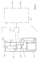
- FIG. 1 An apparatus I according to the invention, diagrammatically shown in figure 1 , is based on the following devices:
- the whole body plethysmograph 102 is structured as follows.
- the booth 12 has a volume of 600 dm 3 and is adapted to allow the seating of a subject 11 whose blood flow dynamics between the trunk and the extremities is to be studied.
- the booth 12 comprises non-transparent parts and transparent parts.
- a mouthpiece 15 Approximately at the level of the mouth of the subject 11, a mouthpiece 15 allows the passage of air from the outside to the inside.
- openings 4 allow the passage of air between the outside and the inside of said booth 12; a traditional flow sensor 40 with a pneumotachograph (provided with Lilly or Silverman or Fleisch resistors) to measure the air flow passing through the openings 4 is applied to each of said openings 4.
- a traditional flow sensor 40 with a pneumotachograph provided with Lilly or Silverman or Fleisch resistors
- the opto-electronic thoraco-abdominal plethysmograph 101 is structured as follows. In front of the booth 12, video cameras 3 are arranged so as to film inside the booth. Such video cameras 3 are connected with an output to an electronic detection device 21.
- a plurality of markers 2, consisting of small plastic half-spheres covered by reflective material is applied to the subject 11 at preset positions on the surface of the trunk.
- the application of such markers 2 is performed by means of the application of double-sided hypoallergenic paper tape.
- Said electronic detection device 21 is an electronic system which provides the value of the volume variation of the trunk ( ⁇ V cx ) on the outside on the basis of processing performed on the digital images obtained from said video cameras 3 by means of the tracing of the positions in space of the markers 2.
- the microprocessor system 20 comprises an integrating circuit 27, an anti-filter 41, an operation block 23 and a differentiator circuit 24.
- the flow sensor 40 provides the value of the gas flow in and out of the lungs. Such a value is integrated by the integrating circuit 27 in order to obtain the changes in gas volume of the lungs.
- Such a value is anti-filtered by the anti-filter 22 (the explanation will be carried out hereafter).
- the values of the outputs of the electronic detection device 21 and clamping circuit 41 are subtracted in the operation block 23 in order to obtain the value of the amount of blood flowing between the trunk and the extremities (V b ) and is provided on the outside.
- V b is provided on the outside, and also differentiated by the differentiator circuit 24 to compute the flow rate P(t) thereof.
- the clamping circuit 41 The reason for the use of the clamping circuit 41 is now explained.
- the subject 11 produces heat giving rise to a thermal drift which must be corrected by moans of high pass filtering of the signal, which however may be difficult to define.
- a correction of the drift is therefore obtained by aligning the ⁇ V cw plots (which are not subject to drift) from the output of the electronic detection device 21 with the output of the anti-filter 22 at the end of the inspiration (when there is usually no blood flow and therefore the two plots coincide) breath by breath and by linearly correcting the signal ⁇ VL in the segment between two points of zero flow at the beginning and end of the inspirations.
- Such a function is performed by the clamping circuit 41.
- the thoraco-abdominal plethysmograph 101 could be formed by an above mentioned respiratory inductance plethysmograph (RIP) instead of an opto-electronic plethysmograph.
- RIP respiratory inductance plethysmograph
- elastic bands 103 comprising electrical coils are used instead of the video cameras 3.
- the apparatus uses an electronic detection device 131 allowing measurement of the self inductance of said electric coils, providing the value of the volute changes of the trunk to the microprocessor system 20.
- the thoraco-abdominal plethysmograph 101 could be formed by the aforementioned thoraco-abdominal plethysmography contained in a shirt 203; the output is read by an electronic detection device 231.
- a product designated as Respitrace produced by Vivometrics could be used.
- the booth 12 does not need to be transparent, as the use of video cameras is not necessary.
- Variants may also be used for the whole body plethysmograph 102, by using, for instance, a volume displacement plethysmograph instead of a variable flow plethysmograph.
- Figure 5 shows a process according to the invention, comprising:
- the latter processing 120 comprises:
Landscapes
- Health & Medical Sciences (AREA)
- Life Sciences & Earth Sciences (AREA)
- General Health & Medical Sciences (AREA)
- Public Health (AREA)
- Pathology (AREA)
- Engineering & Computer Science (AREA)
- Biomedical Technology (AREA)
- Heart & Thoracic Surgery (AREA)
- Medical Informatics (AREA)
- Molecular Biology (AREA)
- Surgery (AREA)
- Veterinary Medicine (AREA)
- Biophysics (AREA)
- Physics & Mathematics (AREA)
- Animal Behavior & Ethology (AREA)
- Hematology (AREA)
- Physiology (AREA)
- Cardiology (AREA)
- Pulmonology (AREA)
- Dentistry (AREA)
- Oral & Maxillofacial Surgery (AREA)
- Measurement Of The Respiration, Hearing Ability, Form, And Blood Characteristics Of Living Organisms (AREA)
- Measuring Pulse, Heart Rate, Blood Pressure Or Blood Flow (AREA)
- Measuring And Recording Apparatus For Diagnosis (AREA)
Abstract
Description
- The present invention relates to a dual body plethysmography apparatus and process for measuring the blood flow between the trunk and the body periphery.
- The measurement of the blood flow between the trunk and the body periphery (term by which the upper limbs, the lower limbs and the head are designated) is extremely important in the understanding of the physiology and physiopathology of cardiopulmonary interaction.
- Changes of the pleural and abdominal pressure have important implications for cerebral blood flow, pulmonary blood volume, cardiac output and ventricular afterload. Changes in these parameters affect alveolar gas exchange and skeletal muscle perfusion particularly during physical exercise with or without limitation of expiratory flow as frequently occurs in chronic obstructive lung disease and asthma. These parameters are also affected by positive pressure mechanical ventilation, negative inspiratory pressures during obstruction of the upper respiratory tract (for instance in obstructive sleep apnoea), strongly positive expiratory pressures as occurs in Valsalva's maneuver, expulsive maneuvers, and cough.
- Some of the aforesaid implications have been described in the following papers:
- Aliverti A., Macklem P.T., "How and why exercise is impaired in COPD", Respiration. 68: 229:239, 2001;
- Aliverti A., R. L. Dellacà, P. Lotti, S. Bertini, R. Duranti, G. Scano, J. Heyman, A. Lo Mauro, A. Pedotti, P. T. Macklem. "Influence of expiratory flow-limitation during exercise on systemic oxygen delivery in humans". European Journal of Applied Physiology, 2005;
- Duke G. J. "Cardiovascular effects of mechanical ventilation". Critical Care and Resuscitation 1999; 1: 388-399;
- H. Fessler, S. Permutt. "Interaction between the circulatory and ventilatory pumps". Thorax: 57, 1995;
- Iandelli I, Aliverti A, Kayser B, Dellacà R, Cala SJ, Duranti R, Kelly S, Scano G, Sliwinski P, Yan S, Macklem PT, Pedotti A. "Determinants of exercise performance in normal men with externally imposed expiratory flow limitation". J Appl Physiol 92: 1943-1952, 2002;
- Lloyd. C.. Mechanical cardiopulmonary interdependence. "J. Appl. Physiol.: Respirat. Environ". Exercise Physiol. 52: 333-339, 1982;
- Lu, K., J.W. Clark, Jr., F.H. Ghorbel, D.L. Ware, and A. Bidani. "A human cardiopulmonary system model applied to the analysis of the Valsalva maneuver". Am J Physiol Heart Circ Physiol 281: H2661-H2679, 2001;
- Miller J.D., Pegelow D.F., Jacques A. J. and Dempsey J. "Effects of augmented respiratory muscle pressure production on locomotor limbs venous return during calf contraction exercise". Articles in Pres. J Appl Physiol, 2005b;
- Permutt S., A. Wise. "Mechanical interaction of respiration and circulation". Handbook of physiology: the respiratory system III: 36, 1986;
- Ranieri V.M., M. Dambrosio, N. Brienza. "Intrinsic PEEP and cardiopulmonary interaction in patients with COPD and acute ventilatory failure". Eur Respir J, 9:1283-1292, 1996;
- Scharf, S.M., J.A. Bianco, D.E. Tow, and R. Brown. "The effects of large negative intrathoracic pressure on left ventricular function in patients with coronary artery disease". Circulation 63: 871-875, 1981;
- Scharf, S.M., R. Brown, N. Saunders, and L.H. Green. "Effects of normal and loaded spontaneous inspiration on cardiovascular function". J. Appl. Physiol.: Respirat. Environ. Exercise Physiol. 47: 582-590, 1979;
- Takata, M., Wise, R. A., and Robotham, J. L. "Effects of abdominal pressure on venous return: abdominal vascular zone conditions". J. Appl. Physiol., 69(6): 1961-1972, 1990.
- There are currently no devices or processes which can measure blood shifts between the trunk and the extremities..
- It is known that, during every respiratory act or maneuver, the variations of the volume defined by the thoraco-abdominal wall (hereafter also indicated by the symbol Δvcw, with reference to the term "chest wall") are determined by the sum of the variations of gas volume in the lung (hereafter also indicated by the symbol ΔVL) and variations of blood volume contained within the trunk. (Vb) according to the equation

- There are known systems to measure ΔVL, by total body plethysmographies or by the acronym WBP, "Whole Body Plethysmography", described in patent
US3511237 ) and consisting in measuring the variations of air flow or volume in a constant pressure booth in which a subject under examination is seated; furthermore, the subject breathes through a mouthpiece which is connected to the outside; finally, there is an opening provided with a special sensor that measures the ΔVL. Two embodiments of such plethysmographies are considered here: - volume plethysmographs: the volume of input/output air to/from the booth is measured; see Mead J. "Volume displacement body plethysmograph for respiratory measurements in human subjects". J Appl Physiol 1960; 15: 736- 740;
- flow plethysmographs: the flow of input/output air to/from the booth is measured; such a flow is then integrated in order to obtain ΔVL;
- There are also known systems for the measurement of the variations of the volume of the trunk (ΔVcw), known as thoraco-abdominal plethysmographs or by the acronym TAP, "Thoraco-Abdominal Plethysmography".
- A first example of thoraco-abdominal plethysmography is given by the opto-electronic plethysmography (also known by the acronym OEP, "Opto-Electronic Plethysmography"), described in patent
ITMI001188A1 - Ferrigno G, Carnevali P, Aliverti A, Molteni F, Beulke G and Pedotti A. "Three-dimensional Optical Analysis of Chest Wall Motion". J Appl Physiol 77(3): 1224-1231, 1994;
- Cala SJ, Kenyon C, Ferrigno G, Carnevali P, Aliverti A, Pedotti A, Macklem PT and Rochester DF. "Chest wall and lung volume estimation by optical reflectance motion analysis". J Appl Physiol 81(6): 2680-2689, 1996;
- Carnevali P, Ferrigno G, Aliverti A and Pedotti A. "A new method for 3D optical analysis of chest wall motion". Technology and Health Care 4: 43-65, 1996;
- Aliverti A, R. Dellacà , P. Pelosi, D. Chiumello, A. Pedotti, L. Gattinoni. "Opto-electronic plethysmography in intensive care patients". Am. J. Respir. Crit. Care Med., 161: 1546-1552, 2000;
- Aliverti A, R. Dellacà, P. Pelosi, D. Chiumello, L. Gattinoni and A. Pedotti. "Compartmental analysis of breathing in the supine and prone positions by Opto-Electronic Plethysmography". Ann Biomed Eng 29: 60-70, 2001;
- Aliverti A, Pedotti A. "Opto-electronic Plethysmography". Monaldi Arch Chest Dis; 59(1): 12-6, 2003.
- Said opto-electronic plethysmography uses digital video cameras to film a subject under examination; reflective markers are applied on the chest and abdomen of such a subject. The markers are filmed by the video cameras, which transmit the filmed sequences to a microprocessor system, which traces the position in space of the markers, and computes the variations of the volume enclosed in the trunk (Vcw) on the basis of a preestablished geometrical model.
-
- Such a respiratory inductance plethysmography uses two separate windings of wire, stitched within an elastic band which is about 10 cm broad, positioned just under the armpits and at the level of the umbilicus. The wires of the two bands, which are equivalent to as many coils, display a self-inductance that varies according to the surface thereof, which in turn depends on the volume variations of the thoraco-abdominal compartment (ΔVcw); in this manner, the volume variations of the thoraco-abdominal compartment (ΔVcw) may be traced by traditional electronic means.
- A third example of thoraco-abdominal plethysmography is described by patent
GB2116725A - Scientific papers in this respect are:
- E. R. Post and M. Orth, "Smart Fabric, or Washable Computing", Proceedings of First International Symposium on Wearable Computers, Cambridge, MA, IEEE Computer Society, Los Alamitos, CA (1997), pp. 167-168;
- Della Santa A, Mazzoldi A, De Rossi D. "Dressware: wearable hardware". Material Sci Eng 1999;C7: 31-37;
- Di Rienzo M, Rizzo F, Parati G, Brambilla G, Ferratini M, Castiglioni P. MagIC System: "a New Textile-Based Wearable Device for Biological Signal Monitoring. Applicability in Daily Life and Clinical Setting". In Proc. IEEE EMB Conference 2005, Shanghai. IEEE Press.
- It is the object of the present invention to obtain an apparatus that measures the blood flow between the trunk and the extremities in a non-invasive manner.
- According to the invention, such an object is achieved by means of an apparatus for measuring the blood flow between the trunk and the extremities (Vb), which comprises a whole body plethysmograph for measuring ΔVL, a thoraco-abdominal plethysmograph for measuring the volume variations of the trunk (ΔVcw) and processing means to analyze said ΔVL with said ΔVcw in order to measure the blood flow between the trunk and the extremities Vb, as the difference between ΔVcw and ΔVL:

- The invention also relates to a process for measuring the blood flow between the trunk and the body periphery (Vb), comprising:
- a measurement of the volume variations of the trunk (ΔVcw) by means of thoraco-abdominal plethysmography;
- a measurement of the variations of gas volume in the lungs (ΔVL) by whole body plethysmography concurrent to the above said thoraco-abdominal plethysmography;
- a processing of the volume variations of the trunk (ΔVcw) and of the volume variations of the lungs so as to measure the blood flow between the trunk and the extremities (Vb).
- By means of an apparatus or a process according to the invention, the blood flow from the trunk to the extremities may be derived from the equation

- Furthermore, by knowing the instantaneous values of the volume variations of the trunk and the values of the variations of gas volume in the lungs, the instantaneous flow rates (indicated by the symbol P(t)) of the blood flowing from the trunk to the extrmities and vice versa, may be derived from the formula

- These and other features of the present invention will become more apparent from the following detailed description of an embodiment thereof by way of no limitation in the accompanying drawings, in which:
-
figure 1 shows a diagrammatic view of the apparatus infigure 1 ; -
figure 2 shows an electric diagram equivalent to the dynamic state of the booth of the plethysmograph infigure 1 ; -
figure 3 shows a view similar to that infigure 1 for a different embodiment of the invention; -
figure 4 shows a view similar to that infigure 1 for a further embodiment of the invention; -
figure 5 shows a block diagram of a procedure according to the invention. - An apparatus I according to the invention, diagrammatically shown in
figure 1 , is based on the following devices: - a thoraco-
abdominal plethysmograph 101, in this case consisting of an opto-electronic plethysmograph, provided with digital video cameras 3 and markers 2; - a
whole body plethysmograph 102, by way of example of the flow-type, provided with abooth 12 with amouthpiece 15,openings 4 and aflow sensor 40; - a
microprocessor processing system 20. - The
whole body plethysmograph 102 is structured as follows. Thebooth 12 has a volume of 600 dm3 and is adapted to allow the seating of a subject 11 whose blood flow dynamics between the trunk and the extremities is to be studied. Thebooth 12 comprises non-transparent parts and transparent parts. Approximately at the level of the mouth of the subject 11, amouthpiece 15 allows the passage of air from the outside to the inside. - On the upper wall of the
booth 12,openings 4 allow the passage of air between the outside and the inside of saidbooth 12; atraditional flow sensor 40 with a pneumotachograph (provided with Lilly or Silverman or Fleisch resistors) to measure the air flow passing through theopenings 4 is applied to each of saidopenings 4. - The opto-electronic thoraco-
abdominal plethysmograph 101 is structured as follows. In front of thebooth 12, video cameras 3 are arranged so as to film inside the booth. Such video cameras 3 are connected with an output to anelectronic detection device 21. - A plurality of markers 2, consisting of small plastic half-spheres covered by reflective material is applied to the subject 11 at preset positions on the surface of the trunk. The application of such markers 2 is performed by means of the application of double-sided hypoallergenic paper tape.
- Said
electronic detection device 21 is an electronic system which provides the value of the volume variation of the trunk (ΔVcx) on the outside on the basis of processing performed on the digital images obtained from said video cameras 3 by means of the tracing of the positions in space of the markers 2. - The
microprocessor system 20 comprises an integratingcircuit 27, an anti-filter 41, anoperation block 23 and adifferentiator circuit 24. - The
flow sensor 40 provides the value of the gas flow in and out of the lungs. Such a value is integrated by the integratingcircuit 27 in order to obtain the changes in gas volume of the lungs. - Such a value is anti-filtered by the anti-filter 22 (the explanation will be carried out hereafter).
- Downstream of the anti-filter 22 there is a clamping
circuit 41. The reason for the use of such aclamping circuit 41 will be explained hereafter. - The values of the outputs of the
electronic detection device 21 and clampingcircuit 41 are subtracted in theoperation block 23 in order to obtain the value of the amount of blood flowing between the trunk and the extremities (Vb) and is provided on the outside. - Finally, such a value Vb is provided on the outside, and also differentiated by the
differentiator circuit 24 to compute the flow rate P(t) thereof. - The reason for the use of the anti-filter 22 is explained hereafter. The dynamical phenomena occurring within the
booth 12 must indeed be taken into account. For this purpose, it is helpful to refer to an equivalent circuit shown infigure 2 , in which: - a current generator (I) represents the variations of lung volume generated by the subject under examination, which partially causes air flow through the walls of the booth and partially compresses the volume of gas contained in the booth during inspiration and decompresses the gas during expiration,
- a capacitance C represents the compressibility of the gas contained in the booth and its value depends on the air volume surrounding the subject 11 (equivalent to the volume of the booth subtracted of the total body volume of the subject). An
impedance 
- a resistance R (and impedance Z 2 = R ; such a resistance is valid when the above said Lilly or Silverman resistors are used; when the above said Fleisch resistors are used, the inductance must also be included) represents the
pneumotachograph 4; - a current I2 represents the gas flow through the
pneumotachograph 4, and results being correlated to I by the following transfer function:

- To correct the attenuation and the phase shift introduced by the booth dynamics it is therefore necessary to apply an appropriate anti-filter consisting of a filter, the transfer function of which is:

where
and
with cut-off frequency fh at high frequencies being forinstance 20 Hz. - The reason for the use of the clamping
circuit 41 is now explained. Within thebooth 12, the subject 11 produces heat giving rise to a thermal drift which must be corrected by moans of high pass filtering of the signal, which however may be difficult to define. A correction of the drift is therefore obtained by aligning the ΔVcw plots (which are not subject to drift) from the output of theelectronic detection device 21 with the output of the anti-filter 22 at the end of the inspiration (when there is usually no blood flow and therefore the two plots coincide) breath by breath and by linearly correcting the signal ΔVL in the segment between two points of zero flow at the beginning and end of the inspirations. Such a function is performed by the clampingcircuit 41. - There may be variants to the embodiment of the present invention.
- For instance, as shown in
figure 3 , the thoraco-abdominal plethysmograph 101 could be formed by an above mentioned respiratory inductance plethysmograph (RIP) instead of an opto-electronic plethysmograph. It should be noted that the above mentionedelastic bands 103 comprising electrical coils are used instead of the video cameras 3. The apparatus uses anelectronic detection device 131 allowing measurement of the self inductance of said electric coils, providing the value of the volute changes of the trunk to themicroprocessor system 20. - According to a further variant, shown in
figure 4 , the thoraco-abdominal plethysmograph 101 could be formed by the aforementioned thoraco-abdominal plethysmography contained in ashirt 203; the output is read by anelectronic detection device 231. For instance, a product designated as Respitrace produced by Vivometrics could be used. - In the two variants just described above, the
booth 12 does not need to be transparent, as the use of video cameras is not necessary. - Variants may also be used for the
whole body plethysmograph 102, by using, for instance, a volume displacement plethysmograph instead of a variable flow plethysmograph. -
Figure 5 shows a process according to the invention, comprising: - a
measurement 104 of the variations of gas volume of the lungs (ΔVL) by means of a whole body plethysmograph.. - a
measurement 121 of the volume variations of the trunk (ΔVcw) by means of thoraco-abdominal plethysmography; such ameasurement 121 is concurrent with the above saidmeasurement 104; saidmeasurement 121 is performed by means of a thoraco-abdominal plethysmograph (which may be, without distinction, an opto-electronic plethysmograph, a respiratory inductance plethysmograph or a plethysmograph contained in clothing,); - a subsequent processing 120 of the volume variations of the trunk (ΔVcw) and of the variations of gas volume of the lungs in order to measure the blood flow between the thoraco-abdominal compartment and the extremities (Vb).
- The latter processing 120 comprises:
- an
anti-filtering 122 of the variations of gas volume of the lungs (ΔVL); - a
drift correction 141 downstream of the anti-filtering 122; - a
computation 123 of the difference between the volume variations of the trunk (ΔVcw) and the volume variations of the lungs (ΔVL) to obtain the volume of blood shifted between the trunk and the extremities (Vb);
Claims (11)
- An apparatus (1) for measuring the blood flow between the trunk and the extremities (Vb), comprising a whole body plethysmograph (102; 4, 12, 15, 22, 40) for measuring the variations of gas volume of the lungs (ΔVL), a thoraco-abdominal plethysmograph (101; 2, 3, 21, 103, 203) for measuring the volume variations of the trunk (ΔVcw) and processing system (20, 21, 22, 23, 24, 41, 131, 231) to measure said variations of gas volume of the lungs (ΔVL) with said volume variations of trunk (ΔVcw) so as to compute the blood shifts between the trunk and the extremities (Vb), said processing system comprising electronic detection devices (21, 131, 231) adapted to measure said volume variations of the trunk (ΔVcw) and a clamping circuit (41) adapted to align the plot of said variations of gas volume of the lungs (ΔVL) with the plot of said volume variations of the trunk (ΔVcw) at the end of the inspiration breath by breath and by linearly correcting the variations of gas volume of the lungs (ΔVL) in the segment between two points of zero flow at the beginning and end of the inspirations.
- An apparatus according to claim 1, characterised by the said thoraco-abdominal plethysmograph (101) is an opto-electronic plethysmograph comprising digital video cameras (3) adapted to film reflective markers (2) placed on the chest and abdomen of a subject being examined (11) seated in a transparent booth (12), with an electronic detection device (21) being provided as connected with an input to said digital video cameras (3), said electronic detection device (21) allowing measurement of the volume variation of the trunk (ΔVcx) on the basis of processing performed on the digital images obtained from said video cameras (3) by means of the tracing of the positions in space of said markers.
- An Apparatus according to claim 1, in which the said thoraco-abdominal plethysmograph (101) is a respiratory inductance plethysmograph computing elastic bands (103) provided with wires, with an electronic detection device (131) being provided, allowing the measurement of the volume variation of the trunk (ΔVcx) on the basis of electric parameters of said wires.
- An apparatus according to claim 1, in which the said thoraco-abdominal plethysmograph (101) is a respiratory inductance plethysmograph contained in a shirt (203), with an electronic detection device (231) being provided, allowing the measurement of the volume variation of the trunk (ΔVcx).
- An apparatus according to any of the preceding claims, characterised by the said whole body variable flow plethysmograph (102) comprising a booth (12) provided with a mouthpiece (15) and openings (4) comprising flow sensors (40).
- An apparatus according to any of claims 1-4, characterised by said volume displacement whole body plethysmograph (102).
- An apparatus according to any of the preceding claims, characterised by an anti-filter (22) with a transfer function


- An apparatus according to any of the preceding claims, characterised by a differentiator circuit (24) allowing to compute the blood flow between the thoraco-abdominal compartment and the periphery (P(t)).
- A process for measuring the blood flow between the trunk and the extremities (Vb), comprising a measurement (121) of the volume variation of the trunk (ΔVcw) by means of a thoraco-abdominal plethysmography, a measurement (104) of the variations of gas volume of the lungs (ΔVL) by means of whole body plethysmography, and a processing (120) of said volume variations of the trunk (ΔVow) and of said volume variations of the lungs (ΔVL) so as to measure the volume of blood shifted between the trunk and the extremities (Vb), said measurements (10, 121) being concurrent, said processing comprising the alignment of the plot of said variations of gas volume of the lungs (ΔVL) with the plot of said volume variations of the trunk (ΔVcw) at the end of the inspiration breath by breath and the linearly correction of the variations of gas volume of the lungs (ΔVL) in the segment between two points of zero flow at the beginning and end of the inspirations.
- A process according to claim 9, characterised by an anti-filtering (122) of said gas volume value in the thoraco-abdominal compartment (ΔVL) by means of an anti-filter (22) with a transfer function


- A process according to any of claims 9-10, characterised by differentiation (124) of the volume of blood shifted between the trunk and the extremities (Vb) allowing computation of the flow rate (P(t)) of blood between the thoraco-abdominal compartment and the periphery.
Applications Claiming Priority (2)
| Application Number | Priority Date | Filing Date | Title |
|---|---|---|---|
| IT001540A ITMI20061540A1 (en) | 2006-08-02 | 2006-08-02 | APPARATUS AND PROCEDURE WITH DOUBLE BODY PLETHESMOGRAPHY FOR THE MEASUREMENT OF BLOOD MOVEMENTS BETWEEN THE THORACO-ABDOMINAL COMPARTMENT AND THE BODY OUTSKIRTS |
| PCT/EP2007/057919 WO2008015222A1 (en) | 2006-08-02 | 2007-07-31 | Dual body plethysmography apparatus and process for measuring blood flow between the thorax and abdomen (the trunk) and the body periphery |
Publications (2)
| Publication Number | Publication Date |
|---|---|
| EP2051632A1 EP2051632A1 (en) | 2009-04-29 |
| EP2051632B1 true EP2051632B1 (en) | 2010-05-12 |
Family
ID=38624019
Family Applications (1)
| Application Number | Title | Priority Date | Filing Date |
|---|---|---|---|
| EP07802445A Not-in-force EP2051632B1 (en) | 2006-08-02 | 2007-07-31 | Dual body plethysmography apparatus and process for measuring blood flow between the thorax and abdomen (the trunk) and the body periphery |
Country Status (6)
| Country | Link |
|---|---|
| US (1) | US20090326396A1 (en) |
| EP (1) | EP2051632B1 (en) |
| AT (1) | ATE467389T1 (en) |
| DE (1) | DE602007006508D1 (en) |
| IT (1) | ITMI20061540A1 (en) |
| WO (1) | WO2008015222A1 (en) |
Families Citing this family (4)
| Publication number | Priority date | Publication date | Assignee | Title |
|---|---|---|---|---|
| US9226695B2 (en) * | 2013-07-02 | 2016-01-05 | Near Margalit | Dual chamber volume measurement apparatus and methods of making and using the same |
| DE102014111528B3 (en) | 2014-08-13 | 2015-07-09 | Carefusion Germany 234 Gmbh | Breath measurement device |
| SG10202012959YA (en) | 2014-09-16 | 2021-01-28 | Willow Innovations Inc | Systems, devices and methods for assessing milk volume expressed from a breast |
| US20160106378A1 (en) * | 2014-10-21 | 2016-04-21 | Xerox Corporation | System and method for detecting an arrhythmic cardiac event from a cardiac signal |
Family Cites Families (13)
| Publication number | Priority date | Publication date | Assignee | Title |
|---|---|---|---|---|
| US3731184A (en) * | 1948-12-21 | 1973-05-01 | H Goldberg | Deformable pick up coil and cooperating magnet for measuring physical quantities, with means for rendering coil output independent of orientation |
| DE1466840C3 (en) * | 1964-12-11 | 1981-10-01 | Jaeger, Erich, 8700 Würzburg | Plethysmograph |
| GB1596298A (en) * | 1977-04-07 | 1981-08-26 | Morgan Ltd P K | Method of and apparatus for detecting or measuring changes in the cross-sectional area of a non-magnetic object |
| US4433693A (en) * | 1979-09-27 | 1984-02-28 | Hochstein Peter A | Method and assembly for monitoring respiration and detecting apnea |
| US4494553A (en) * | 1981-04-01 | 1985-01-22 | F. William Carr | Vital signs monitor |
| US4373534A (en) * | 1981-04-14 | 1983-02-15 | Respitrace Corporation | Method and apparatus for calibrating respiration monitoring system |
| US4452252A (en) * | 1981-05-26 | 1984-06-05 | Respitrace Corporation | Non-invasive method for monitoring cardiopulmonary parameters |
| GB2116725B (en) * | 1982-03-15 | 1985-07-03 | Scotland The Secretary Of Stat | Respiration monitor |
| US4834109A (en) * | 1986-01-21 | 1989-05-30 | Respitrace Corporation | Single position non-invasive calibration technique |
| US4807640A (en) * | 1986-11-19 | 1989-02-28 | Respitrace Corporation | Stretchable band-type transducer particularly suited for respiration monitoring apparatus |
| US4817625A (en) * | 1987-04-24 | 1989-04-04 | Laughton Miles | Self-inductance sensor |
| US5331968A (en) * | 1990-10-19 | 1994-07-26 | Gerald Williams | Inductive plethysmographic transducers and electronic circuitry therefor |
| DE4439080B4 (en) * | 1994-11-02 | 2004-06-03 | Ganshorn Medizin Electronic Gmbh | Whole-body plethysmograph |
-
2006
- 2006-08-02 IT IT001540A patent/ITMI20061540A1/en unknown
-
2007
- 2007-07-31 DE DE602007006508T patent/DE602007006508D1/en active Active
- 2007-07-31 AT AT07802445T patent/ATE467389T1/en not_active IP Right Cessation
- 2007-07-31 WO PCT/EP2007/057919 patent/WO2008015222A1/en not_active Ceased
- 2007-07-31 US US12/309,757 patent/US20090326396A1/en not_active Abandoned
- 2007-07-31 EP EP07802445A patent/EP2051632B1/en not_active Not-in-force
Also Published As
| Publication number | Publication date |
|---|---|
| US20090326396A1 (en) | 2009-12-31 |
| ATE467389T1 (en) | 2010-05-15 |
| EP2051632A1 (en) | 2009-04-29 |
| WO2008015222A1 (en) | 2008-02-07 |
| DE602007006508D1 (en) | 2010-06-24 |
| ITMI20061540A1 (en) | 2008-02-03 |
Similar Documents
| Publication | Publication Date | Title |
|---|---|---|
| Lanatà et al. | Comparative evaluation of susceptibility to motion artifact in different wearable systems for monitoring respiratory rate | |
| Aliverti et al. | Opto-electronic plethysmography | |
| EP3646786B1 (en) | Body-worn system for continuous, noninvasive measurement of at least one of cardiac output and stroke volume from a patient | |
| CN101528126B (en) | Method and device for the determination of breath frequency | |
| Lapi et al. | Respiratory rate assessments using a dual-accelerometer device | |
| US20150289785A1 (en) | Apparatus and Method for Monitoring Respiration Volumes and Synchronization of Triggering in Mechanical Ventilation by Measuring the Local Curvature of the Torso Surface | |
| WO2018042376A1 (en) | Method and system for the detection of the respiratory profile of a patient undergoing non invasive respiratory assistance by nasal cannulas or other interface | |
| WO1998026710A1 (en) | Apparatus and method for non-invasively measuring cardiac output | |
| CN109512410A (en) | A kind of more physiological signal Fusion Features without cuff continuous BP measurement method | |
| US20090326396A1 (en) | Dual body plethysmography apparatus and process for measuring blood flow between the thorax and abdomen (the trunk) and the body periphery | |
| Solà et al. | Wearable PWV technologies to measure blood pressure: eliminating brachial cuffs | |
| Piacentini et al. | A new automated method versus continuous positive airway pressure method for measuring pressure–volume curves in patients with acute lung injury | |
| CN116327171A (en) | A method of extracting respiratory wave signal based on pulse wave | |
| Vicario et al. | Noninvasive estimation of alveolar pressure | |
| Liu et al. | A principal component analysis based data fusion method for estimation of respiratory volume | |
| EP4056112B1 (en) | Method for determining respiratory timing parameters from respiratory monitoring measurements of a subject | |
| Navajas et al. | A simplified method for monitoring respiratory impedance during continuous positive airway pressure | |
| Chapman et al. | Estimating lung mechanics of dogs with unilateral lung injury | |
| Hilbert et al. | Optimal pressure support level for beginning weaning in patients with COPD: Measurement of diaphragmatic activity with step-by-step decreasing pressure support level | |
| Kohler et al. | Non-invasive, side-selective nasal airflow monitoring | |
| Johansson et al. | Sensors for respiratory monitoring | |
| Milner et al. | Measurement of lung function | |
| HK1227666A (en) | Body-worn system for continous, noninvasive measurement of cardiac output, stroke volume, cardiac power, and blood pressure | |
| HK1227666A1 (en) | Body-worn system for continous, noninvasive measurement of cardiac output, stroke volume, cardiac power, and blood pressure | |
| Ackerman et al. | An automated, noninvasive method for measuring chest-wall motion during high-frequency oscillation |
Legal Events
| Date | Code | Title | Description |
|---|---|---|---|
| PUAI | Public reference made under article 153(3) epc to a published international application that has entered the european phase |
Free format text: ORIGINAL CODE: 0009012 |
|
| 17P | Request for examination filed |
Effective date: 20090225 |
|
| AK | Designated contracting states |
Kind code of ref document: A1 Designated state(s): AT BE BG CH CY CZ DE DK EE ES FI FR GB GR HU IE IS IT LI LT LU LV MC MT NL PL PT RO SE SI SK TR |
|
| AX | Request for extension of the european patent |
Extension state: AL BA HR MK RS |
|
| GRAP | Despatch of communication of intention to grant a patent |
Free format text: ORIGINAL CODE: EPIDOSNIGR1 |
|
| DAX | Request for extension of the european patent (deleted) | ||
| GRAS | Grant fee paid |
Free format text: ORIGINAL CODE: EPIDOSNIGR3 |
|
| GRAA | (expected) grant |
Free format text: ORIGINAL CODE: 0009210 |
|
| AK | Designated contracting states |
Kind code of ref document: B1 Designated state(s): AT BE BG CH CY CZ DE DK EE ES FI FR GB GR HU IE IS IT LI LT LU LV MC MT NL PL PT RO SE SI SK TR |
|
| REG | Reference to a national code |
Ref country code: GB Ref legal event code: FG4D |
|
| REG | Reference to a national code |
Ref country code: CH Ref legal event code: EP |
|
| REG | Reference to a national code |
Ref country code: IE Ref legal event code: FG4D |
|
| REF | Corresponds to: |
Ref document number: 602007006508 Country of ref document: DE Date of ref document: 20100624 Kind code of ref document: P |
|
| REG | Reference to a national code |
Ref country code: NL Ref legal event code: VDEP Effective date: 20100512 |
|
| LTIE | Lt: invalidation of european patent or patent extension |
Effective date: 20100512 |
|
| PG25 | Lapsed in a contracting state [announced via postgrant information from national office to epo] |
Ref country code: ES Free format text: LAPSE BECAUSE OF FAILURE TO SUBMIT A TRANSLATION OF THE DESCRIPTION OR TO PAY THE FEE WITHIN THE PRESCRIBED TIME-LIMIT Effective date: 20100823 Ref country code: LT Free format text: LAPSE BECAUSE OF FAILURE TO SUBMIT A TRANSLATION OF THE DESCRIPTION OR TO PAY THE FEE WITHIN THE PRESCRIBED TIME-LIMIT Effective date: 20100512 Ref country code: NL Free format text: LAPSE BECAUSE OF FAILURE TO SUBMIT A TRANSLATION OF THE DESCRIPTION OR TO PAY THE FEE WITHIN THE PRESCRIBED TIME-LIMIT Effective date: 20100512 Ref country code: SE Free format text: LAPSE BECAUSE OF FAILURE TO SUBMIT A TRANSLATION OF THE DESCRIPTION OR TO PAY THE FEE WITHIN THE PRESCRIBED TIME-LIMIT Effective date: 20100512 |
|
| PG25 | Lapsed in a contracting state [announced via postgrant information from national office to epo] |
Ref country code: SI Free format text: LAPSE BECAUSE OF FAILURE TO SUBMIT A TRANSLATION OF THE DESCRIPTION OR TO PAY THE FEE WITHIN THE PRESCRIBED TIME-LIMIT Effective date: 20100512 Ref country code: FI Free format text: LAPSE BECAUSE OF FAILURE TO SUBMIT A TRANSLATION OF THE DESCRIPTION OR TO PAY THE FEE WITHIN THE PRESCRIBED TIME-LIMIT Effective date: 20100512 Ref country code: IS Free format text: LAPSE BECAUSE OF FAILURE TO SUBMIT A TRANSLATION OF THE DESCRIPTION OR TO PAY THE FEE WITHIN THE PRESCRIBED TIME-LIMIT Effective date: 20100912 Ref country code: LV Free format text: LAPSE BECAUSE OF FAILURE TO SUBMIT A TRANSLATION OF THE DESCRIPTION OR TO PAY THE FEE WITHIN THE PRESCRIBED TIME-LIMIT Effective date: 20100512 Ref country code: AT Free format text: LAPSE BECAUSE OF FAILURE TO SUBMIT A TRANSLATION OF THE DESCRIPTION OR TO PAY THE FEE WITHIN THE PRESCRIBED TIME-LIMIT Effective date: 20100512 |
|
| PG25 | Lapsed in a contracting state [announced via postgrant information from national office to epo] |
Ref country code: CY Free format text: LAPSE BECAUSE OF FAILURE TO SUBMIT A TRANSLATION OF THE DESCRIPTION OR TO PAY THE FEE WITHIN THE PRESCRIBED TIME-LIMIT Effective date: 20100609 Ref country code: PL Free format text: LAPSE BECAUSE OF FAILURE TO SUBMIT A TRANSLATION OF THE DESCRIPTION OR TO PAY THE FEE WITHIN THE PRESCRIBED TIME-LIMIT Effective date: 20100512 |
|
| PG25 | Lapsed in a contracting state [announced via postgrant information from national office to epo] |
Ref country code: DK Free format text: LAPSE BECAUSE OF FAILURE TO SUBMIT A TRANSLATION OF THE DESCRIPTION OR TO PAY THE FEE WITHIN THE PRESCRIBED TIME-LIMIT Effective date: 20100512 Ref country code: EE Free format text: LAPSE BECAUSE OF FAILURE TO SUBMIT A TRANSLATION OF THE DESCRIPTION OR TO PAY THE FEE WITHIN THE PRESCRIBED TIME-LIMIT Effective date: 20100512 Ref country code: PT Free format text: LAPSE BECAUSE OF FAILURE TO SUBMIT A TRANSLATION OF THE DESCRIPTION OR TO PAY THE FEE WITHIN THE PRESCRIBED TIME-LIMIT Effective date: 20100913 |
|
| PG25 | Lapsed in a contracting state [announced via postgrant information from national office to epo] |
Ref country code: RO Free format text: LAPSE BECAUSE OF FAILURE TO SUBMIT A TRANSLATION OF THE DESCRIPTION OR TO PAY THE FEE WITHIN THE PRESCRIBED TIME-LIMIT Effective date: 20100512 Ref country code: BE Free format text: LAPSE BECAUSE OF FAILURE TO SUBMIT A TRANSLATION OF THE DESCRIPTION OR TO PAY THE FEE WITHIN THE PRESCRIBED TIME-LIMIT Effective date: 20100512 Ref country code: CZ Free format text: LAPSE BECAUSE OF FAILURE TO SUBMIT A TRANSLATION OF THE DESCRIPTION OR TO PAY THE FEE WITHIN THE PRESCRIBED TIME-LIMIT Effective date: 20100512 Ref country code: MC Free format text: LAPSE BECAUSE OF NON-PAYMENT OF DUE FEES Effective date: 20100731 Ref country code: SK Free format text: LAPSE BECAUSE OF FAILURE TO SUBMIT A TRANSLATION OF THE DESCRIPTION OR TO PAY THE FEE WITHIN THE PRESCRIBED TIME-LIMIT Effective date: 20100512 |
|
| PLBE | No opposition filed within time limit |
Free format text: ORIGINAL CODE: 0009261 |
|
| STAA | Information on the status of an ep patent application or granted ep patent |
Free format text: STATUS: NO OPPOSITION FILED WITHIN TIME LIMIT |
|
| 26N | No opposition filed |
Effective date: 20110215 |
|
| REG | Reference to a national code |
Ref country code: FR Ref legal event code: ST Effective date: 20110331 |
|
| PG25 | Lapsed in a contracting state [announced via postgrant information from national office to epo] |
Ref country code: FR Free format text: LAPSE BECAUSE OF NON-PAYMENT OF DUE FEES Effective date: 20100802 Ref country code: GR Free format text: LAPSE BECAUSE OF FAILURE TO SUBMIT A TRANSLATION OF THE DESCRIPTION OR TO PAY THE FEE WITHIN THE PRESCRIBED TIME-LIMIT Effective date: 20100813 |
|
| REG | Reference to a national code |
Ref country code: DE Ref legal event code: R097 Ref document number: 602007006508 Country of ref document: DE Effective date: 20110214 |
|
| PG25 | Lapsed in a contracting state [announced via postgrant information from national office to epo] |
Ref country code: IE Free format text: LAPSE BECAUSE OF NON-PAYMENT OF DUE FEES Effective date: 20100731 |
|
| PG25 | Lapsed in a contracting state [announced via postgrant information from national office to epo] |
Ref country code: MT Free format text: LAPSE BECAUSE OF FAILURE TO SUBMIT A TRANSLATION OF THE DESCRIPTION OR TO PAY THE FEE WITHIN THE PRESCRIBED TIME-LIMIT Effective date: 20100512 |
|
| REG | Reference to a national code |
Ref country code: CH Ref legal event code: PL |
|
| PG25 | Lapsed in a contracting state [announced via postgrant information from national office to epo] |
Ref country code: LI Free format text: LAPSE BECAUSE OF NON-PAYMENT OF DUE FEES Effective date: 20110731 Ref country code: CH Free format text: LAPSE BECAUSE OF NON-PAYMENT OF DUE FEES Effective date: 20110731 |
|
| PG25 | Lapsed in a contracting state [announced via postgrant information from national office to epo] |
Ref country code: HU Free format text: LAPSE BECAUSE OF FAILURE TO SUBMIT A TRANSLATION OF THE DESCRIPTION OR TO PAY THE FEE WITHIN THE PRESCRIBED TIME-LIMIT Effective date: 20101113 Ref country code: BG Free format text: LAPSE BECAUSE OF FAILURE TO SUBMIT A TRANSLATION OF THE DESCRIPTION OR TO PAY THE FEE WITHIN THE PRESCRIBED TIME-LIMIT Effective date: 20100512 Ref country code: LU Free format text: LAPSE BECAUSE OF NON-PAYMENT OF DUE FEES Effective date: 20100731 |
|
| PG25 | Lapsed in a contracting state [announced via postgrant information from national office to epo] |
Ref country code: TR Free format text: LAPSE BECAUSE OF FAILURE TO SUBMIT A TRANSLATION OF THE DESCRIPTION OR TO PAY THE FEE WITHIN THE PRESCRIBED TIME-LIMIT Effective date: 20100512 |
|
| PG25 | Lapsed in a contracting state [announced via postgrant information from national office to epo] |
Ref country code: BG Free format text: LAPSE BECAUSE OF FAILURE TO SUBMIT A TRANSLATION OF THE DESCRIPTION OR TO PAY THE FEE WITHIN THE PRESCRIBED TIME-LIMIT Effective date: 20100812 |
|
| PGFP | Annual fee paid to national office [announced via postgrant information from national office to epo] |
Ref country code: IT Payment date: 20170508 Year of fee payment: 11 |
|
| PGFP | Annual fee paid to national office [announced via postgrant information from national office to epo] |
Ref country code: GB Payment date: 20170721 Year of fee payment: 11 Ref country code: DE Payment date: 20170731 Year of fee payment: 11 |
|
| REG | Reference to a national code |
Ref country code: DE Ref legal event code: R119 Ref document number: 602007006508 Country of ref document: DE |
|
| GBPC | Gb: european patent ceased through non-payment of renewal fee |
Effective date: 20180731 |
|
| PG25 | Lapsed in a contracting state [announced via postgrant information from national office to epo] |
Ref country code: GB Free format text: LAPSE BECAUSE OF NON-PAYMENT OF DUE FEES Effective date: 20180731 Ref country code: DE Free format text: LAPSE BECAUSE OF NON-PAYMENT OF DUE FEES Effective date: 20190201 |
|
| PG25 | Lapsed in a contracting state [announced via postgrant information from national office to epo] |
Ref country code: IT Free format text: LAPSE BECAUSE OF NON-PAYMENT OF DUE FEES Effective date: 20180731 |