EP2051573A2 - Container box, electric connection box provided with container box and method of molding container box - Google Patents
Container box, electric connection box provided with container box and method of molding container box Download PDFInfo
- Publication number
- EP2051573A2 EP2051573A2 EP08017821A EP08017821A EP2051573A2 EP 2051573 A2 EP2051573 A2 EP 2051573A2 EP 08017821 A EP08017821 A EP 08017821A EP 08017821 A EP08017821 A EP 08017821A EP 2051573 A2 EP2051573 A2 EP 2051573A2
- Authority
- EP
- European Patent Office
- Prior art keywords
- box
- mold
- ribs
- outer box
- container
- Prior art date
- Legal status (The legal status is an assumption and is not a legal conclusion. Google has not performed a legal analysis and makes no representation as to the accuracy of the status listed.)
- Granted
Links
- 238000000465 moulding Methods 0.000 title claims abstract description 25
- 238000000034 method Methods 0.000 title claims description 14
- 230000003247 decreasing effect Effects 0.000 claims abstract description 12
- 238000003780 insertion Methods 0.000 claims description 29
- 230000037431 insertion Effects 0.000 claims description 29
- 210000000078 claw Anatomy 0.000 claims description 22
- 238000010276 construction Methods 0.000 description 8
- 230000002093 peripheral effect Effects 0.000 description 6
- 230000002411 adverse Effects 0.000 description 4
- 238000004519 manufacturing process Methods 0.000 description 4
- 238000003825 pressing Methods 0.000 description 4
- 239000000470 constituent Substances 0.000 description 2
- 239000011347 resin Substances 0.000 description 2
- 229920005989 resin Polymers 0.000 description 2
- 230000015572 biosynthetic process Effects 0.000 description 1
- 239000000463 material Substances 0.000 description 1
- 238000012986 modification Methods 0.000 description 1
- 230000004048 modification Effects 0.000 description 1
- 230000000717 retained effect Effects 0.000 description 1
Images



Classifications
-
- H—ELECTRICITY
- H05—ELECTRIC TECHNIQUES NOT OTHERWISE PROVIDED FOR
- H05K—PRINTED CIRCUITS; CASINGS OR CONSTRUCTIONAL DETAILS OF ELECTRIC APPARATUS; MANUFACTURE OF ASSEMBLAGES OF ELECTRICAL COMPONENTS
- H05K7/00—Constructional details common to different types of electric apparatus
- H05K7/02—Arrangements of circuit components or wiring on supporting structure
- H05K7/026—Multiple connections subassemblies
Definitions
- This invention relates to a container box, an electric connection box provided with this container box and a method of molding this container box.
- a conventional electric connection box of the type comprising a case body of a generally rectangular box-shape for receiving, for example, a plurality of fuses, and a cover attached to the case body (see, for example, JP-A-2001-44654 ).
- retaining claws for preventing the disengagement of the cover are formed at an open end of the case body to which the cover body is attached, and these retaining claws are formed respectively at distal ends of elastic piece portions, and the cover is held in position by the resiliency of the elastic piece portions, and therefore is prevented from shaking.
- ribs extending in a fitting direction of the electronic unit are usually formed on an inner surface of the case body or an outer surface of the electronic unit so as to prevent the shaking of the electronic unit, since the electronic unit is liable to be adversely affected by vibrations.
- the height of each rib is smaller at the inlet side (the open end side) of the case body, and is larger at the inner end side (the bottom side) of the case body so that the mold can be easily removed from the open end of the case body.
- This invention has been made in view of the above problems, and an object of the invention is to provide a container box which can positively prevent the shaking, an electric connection box provided with this container box, and a method of molding the container box.
- the ribs having respective inclined edges are formed on the inner surface of the outer box, and extend in the fitting direction, and in order that the molds can be easily removed after the molding, these ribs include the normally-inclined ribs gradually increasing in height in the fitting direction of the inner box, and the reversely-inclined ribs gradually decreasing in height in the fitting direction of the inner box. Therefore, a sufficient pressing force against the inner box can be obtained, and any unnecessary clearance is not formed, and the shaking of the inner box can be positively prevented.
- the container box 10 of the construction of the above Paragraph (1) is employed in the electrical connection box which is liable to be adversely affected by vibrations, and therefore the reliability and durability of the electrical connection box can be enhanced.
- the normally-inclined ribs are formed using the first recesses formed in the surface of the mold for forming the inner surface of the outer box and extending in the insertion/withdrawal direction
- the reversely-inclined ribs are formed using the second recesses formed in the insert dies (which are withdrawn from the molds in the direction of insertion of the first mold into the second mold) and extending in the insertion/withdrawal direction. Therefore, the normally-inclined ribs and the reversely-inclined ribs can be formed with a reduced number of steps, and the outer box can be formed efficiently, and the efficiency of the production can be enhanced.
- the insert dies are used also to form the retaining claws, and therefore the step of forming the retaining claws and the step of forming the normally-inclined ribs and the reversely-inclined ribs can be combined into one step, and besides the structure of the mold device can be simplified. Therefore, the outer box can be formed more efficiently, and the efficiency of the production can be more enhanced.
- the container box which can positively prevent the shaking, the electric connection box with this container box, and the method of molding this container box.
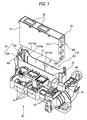
- Fig. 1 is a perspective view showing a preferred embodiment of a container box of the invention and an electric connection box provided with this container box
- Fig. 2A is a plan view of an outer box
- Fig. 2B is a cross-sectional view taken along the line B-B of Fig. 2A
- Fig. 2C is a cross-sectional view taken along the line C-C of Fig. 2A
- Fig. 2D is a cross-sectional view taken along the line D-D of Fig. 2A
- Fig. 3A is a side-elevational view of a rib gradually increasing in height in a fitting (inserting) direction
- Fig. 3A is a side-elevational view of a rib gradually increasing in height in a fitting (inserting) direction
- Fig. 3A is a side-elevational view of a rib gradually increasing in height in a fitting (inserting) direction
- Fig. 3A is a side
- FIG. 3B is a side-elevational view of a rib gradually decreasing in height in the fitting direction
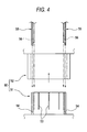
- Fig. 4 is a schematic front-elevational view showing molds for molding the container body of the invention
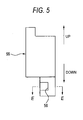
- Fig. 5 is a lateral front-elevational view of an insert die for forming a retaining claw
- Fig. 6 is a cross-sectional view taken along the line E-E of Fig. 5 .
- the electric connection box 40 of this embodiment comprises the container box 10, and is installed, for example, on a wall disposed adjacent to a lower end of a driver's seat within a compartment of an automobile, and controls electrical functions of the automobile.
- the electric connection box 40 includes connectors 41, fuses 42, relays 43, fusible links 44, etc., provided at the outer periphery of the outer box 20 of the container box 10 described later. Cavity portions for receiving the connectors 41, the fuses 42, the relays 43, the fusible links 44, etc., and the outer box 20 are molded integrally with each other, using a resin..
- An electronic unit such as a BCM (body control module (also called an ECU)), is used as an inner box 30 of the container box 10 described later.
- BCM body control module (also called an ECU)
- the container box 10 comprises the hollow outer box 20 having an opening 21 formed in one of upper and lower end faces (here, the upper face is open), and the inner box 30 which can be fitted (inserted) into the outer box 20 through the opening 21.
- a plurality of ribs 11 are formed on an inner surface (inner peripheral surface) 22 of the outer box 20, and extend in a fitting direction of the inner box 30.
- the inner box 30 is in the form of a rectangular box made of a resin, and this inner box 30 is so sized as to be fitted into the outer box 20.
- Connectors 32 for connection to power lines and signal lines are formed in an upper face of the inner box 30.
- Retaining projections 33 are formed respectively at upper end portions of shorter faces 31a of the inner box 30, and when the inner box 30 is fitted into the outer box 20, these retaining projections 33 are retained respectively by retaining portions 23 of the outer box 20, thereby preventing the inner box 30 from being disengaged from the outer box 20.
- the outer box 20 has a rectangular box-shape, and has the opening 21 (serving as an insertion port for the inner box 30) formed at its upper end.
- the outer box 20 includes a pair of opposed longer surfaces 22a and 22a having a larger width, and a pair of opposed shorter surfaces 22b and 22b (extending substantially perpendicular to the direction of extending of the longer surfaces 22a and 22a) having a smaller width.
- the retaining portions 23 (which retain the respective retaining projections 33 of the inner box 30 to prevent the disengagement of the inner box 30) are formed respectively at upper end portions (an edge portion of the opening 21) of the opposed shorter surfaces 22b.
- Each retaining portion 23 has the retaining claw 23a (for retaining engagement with the retaining projection 33 of the inner box 30) formed at its distal end, and this retaining claw 23a is supported by an elastic portion 23b so as to be outwardly displaced. Therefore, when the inner box 30 is fitted into the outer box 20, the retaining projections 33 of the inner box 30 are brought into abutting engagement with the distal ends of the respective retaining claws 23a, and the elastic portions 23b are elastically deformed outwardly, so that the retaining claws 23a are displaced outwardly (that is, away from each other).
- the ribs 11 are formed on the four surfaces 22a and 22b of the inner peripheral surface 22 of the outer box 20.
- Three ribs 11a, 11b and 11c are formed respectively at one end portion, a central portion and the other end portion of each longer surface 22a, and ribs 11d and 11e are formed respectively on opposite side portions of each shorter surface 22b, with the retaining claw 23 interposed therebetween.
- the ribs when called collectively, will be designated by reference numeral 11, and the ribs, when distinguished from one another, will be designated by reference numerals 11a, 11 b, ..., 11e.
- the ribs 11a, 11b and 11c formed on each longer surface 22a are gradually increasing in height in the fitting direction (that is, toward the lower surface of the outer box 20) (These ribs 11a, 11b and 11c will hereinafter be referred to as "normally-inclined ribs").
- the rib 11d formed on each shorter surface 22b is the normally-inclined rib, and therefore is gradually increasing in height in the fitting direction, while the other rib 11e on the shorter surface 22b is gradually decreasing in height in the fitting direction (This rib 11e will hereinafter be referred to as "the reversely-inclined rib"). Namely, edges of the ribs 11e are inclined in the direction opposite to the direction of inclination of edges of the other ribs 11a to 11d.
- the ribs 11 can be inclined over their entire length as shown in Figs. 3A and 3B .
- an inclined portion may be formed, for example, at part of each rib 11.
- a notch 24a is formed through a central portion of a bottom wall 24 of the outer box 20.
- a pair of notches 24b are also formed respectively through opposite end portions of the bottom wall 24 disposed immediately adjacent respectively to the lower ends of the shorter surface 22b.
- the notches 24b are formed for withdrawing insert dies for molding the retaining claws 23a at the upper end portions of the shorter surfaces 22b.
- the outer box 20 is molded by the use of a mold device 50 shown in Fig. 4 , and this mold device 50 comprises a pair of male and female molds 51 and 52 which can be inserted and withdrawn relative to each other in an insertion/withdrawal direction parallel to the fitting direction of the inner box 30 into the outer box 20, and insert dies 55 and 55 which can be inserted into and withdrawn respectively from gaps 54 formed between the combined male and female molds 51 and 52 and extending in the insertion/withdrawal direction.
- Recesses (or grooves) 53 are formed in an outer peripheral surface of the male mold (first mold) 51 for forming the inner peripheral surface 22 of the outer box 20, and extend in the insertion/withdrawal direction.
- the normally-inclined ribs 11a to 11d are formed using the recesses 53 and the female mold (second mold) 52 opposed to the male mold 51 and movable relative to the male mold 51 in the insertion/withdrawal direction. Also, the insert dies 55 and 55 are inserted respectively into the gaps 54, and the retaining claws 23a are formed between the male mold 51 and the female mold 52, and the reversely-inclined ribs 11e are formed, using recesses 56 formed respectively in the insert dies 55 and 55.
- each of the recesses 53 for respectively forming the normally-inclined ribs 11a to 11d is gradually increasing in depth from a proximal end portion (lower end portion in Fig. 4 ) of the male mold 51 toward a distal end portion (upper end portion in Fig. 4 ) thereof, and therefore after the normally-inclined ribs 11a to 11d are formed, the male mold 51 can be easily removed from the molded product (that is, the outer box 20).
- the insert dies 55 must be prepared for forming the retaining claws 23a in the respective gaps 54 formed between the male and female molds 51 and 52 and extending in the insertion/withdrawal direction.
- the insert dies 55 are inserted toward the male mold 51 from a proximal end (upper end in Fig. 4 ) of the female mold 52, and therefore the direction of insertion of these insert dies 55 is opposite to the direction of insertion of the male mold 51.
- the recesses 56 for forming the respective ribs 11e are formed respectively in side surfaces of the insert dies 55, and extend in the insertion/withdrawal direction as shown in Figs. 4 and 5 .
- the recess 56 is gradually increasing in depth in the direction of insertion of the insert die 55. Therefore, in this molding method, the reversely-inclined rib 11e and the retaining claw 23a can be mold by one mold.
- the insert dies 55 are removed upwardly ( Fig. 4 ) from the proximal end of the female mold 52, and therefore the notches 24b are formed in the bottom wall 24 of the outer box 20.
- Fig. 5 shows the lateral front side of the left insert die 55 of Fig. 4 .
- the ribs 11 having the respective inclined edges are formed on the inner peripheral surface 22 of the outer box 20, and extend in the fitting direction of the inner box 30 into the outer box 20, and in order that the molds can be easily removed after the molding, these ribs 11 include the normally-inclined ribs 11a to 11d gradually increasing in height in the fitting direction of the inner box 30, and the reversely-inclined ribs 11e gradually decreasing in height in the fitting direction of the inner box 30.
- the container box 10 of the above construction (including the normally-inclined ribs 11a to 11d gradually increasing in height in the fitting direction of the inner box 30, and the reversely-inclined ribs 11e gradually decreasing in height in the fitting direction of the inner box 30) is employed in the electrical connection box 40 which is liable to be adversely affected by vibrations, and therefore the reliability and durability of the electrical connection box can be enhanced.
- the normally-inclined ribs 11a to 11d are formed using the recesses 53 formed in the surface of the male mold 51 for forming the inner peripheral surface of the outer box 20 and extending in the insertion/withdrawal direction
- the reversely-inclined ribs 11e are formed using the recesses 56 formed in the insert dies 55 (which are withdrawn from the molds in the direction of insertion of the male mold 51 into the female mold 52) and extending in the insertion/withdrawal direction. Therefore, the normally-inclined ribs 11a to 11d and the reversely-inclined ribs 11e can be formed with a reduced number of steps, and the outer box 20 can be formed efficiently, and the efficiency of the production can be enhanced.
- the insert dies 55 are used also to form the retaining claws 23a, and therefore the step of forming the retaining claws 23a and the step of forming the normally-inclined ribs 11a to 11d and the reversely-inclined ribs 11e can be combined into one step, and besides the structure of the mold device 50 can be simplified. Therefore, the outer box 20 can be formed more efficiently, and the efficiency of the production can be more enhanced.
- the present invention is not limited to the above embodiment, and suitable modifications; improvements, etc., can be made. Furthermore, the material, shape, dimensions, numerical values, form, number, disposition, etc., of each of the constituent elements of the above embodiment are arbitrary and are not limited in so far as the invention can be achieved.
- the ribs 11 are formed only on the inner surface 22 of the outer box 20
- reversely-inclined ribs gradually decreasing in height in the fitting direction of the inner box 30 may be formed on the outer surface 31 of the inner box 30, in which case the formation of the ribs 11e on the inner surface 22 of the outer box 20 may be omitted.
- the normally-inclined rib 11d and the reversely-inclined rib 11e are formed on each shorter surface 22b of the outer box 20
- the normally-inclined ribs and the reversely-inclined rib can be formed on each longer surface 22a, or the normally-inclined ribs and the reversely-inclined ribs can be formed on both of each shorter surface 22b and each longer surface 22a.
- the invention is directed to the electric connection box 40 adapted to be installed in the compartment of the automobile, the invention can be applied to the type of electric connection box adapted to be installed at any other portion.
- the electric connection box 40 includes the BCM serving as the inner box 30, the invention can be applied to various connectors.
- the structure of the outer box 20 can be applied to a female housing of such a connector
- the structure of the inner box 30 can be applied to a male housing for fitting into the female housing.
- the inner box 30 fitted into the outer box 20 is not an essential constituent element of the container box 10, and therefore may be omitted.
Landscapes
- Engineering & Computer Science (AREA)
- Microelectronics & Electronic Packaging (AREA)
- Connection Or Junction Boxes (AREA)
- Casings For Electric Apparatus (AREA)
- Moulds For Moulding Plastics Or The Like (AREA)
Abstract
Description
- This invention relates to a container box, an electric connection box provided with this container box and a method of molding this container box.
- There is known a conventional electric connection box of the type comprising a case body of a generally rectangular box-shape for receiving, for example, a plurality of fuses, and a cover attached to the case body (see, for example,
JP-A-2001-44654 - In such an electric connection box, retaining claws for preventing the disengagement of the cover are formed at an open end of the case body to which the cover body is attached, and these retaining claws are formed respectively at distal ends of elastic piece portions, and the cover is held in position by the resiliency of the elastic piece portions, and therefore is prevented from shaking.
- In the case where an electronic unit such as a BCM (body control module (also called an ECU)) is fitted (inserted) into the case body through the open end thereof, ribs extending in a fitting direction of the electronic unit are usually formed on an inner surface of the case body or an outer surface of the electronic unit so as to prevent the shaking of the electronic unit, since the electronic unit is liable to be adversely affected by vibrations.
- However, in the case where the ribs extending in the fitting direction are formed on this kind of case body by the use of molds, it is necessary to gradually change the height of the ribs because of limitations on the molding operation effected by the molds. Namely, in the conventional mold device, the height of each rib is smaller at the inlet side (the open end side) of the case body, and is larger at the inner end side (the bottom side) of the case body so that the mold can be easily removed from the open end of the case body. When the ribs are thus gradually changing in height in one direction, it is feared that a sufficient pressing force can not be obtained in the vicinity of the end portion where the height of the ribs are small, or an unnecessary clearance may be formed, so that the shaking cannot be eliminated, thus leaving room for improvement.
- This invention has been made in view of the above problems, and an object of the invention is to provide a container box which can positively prevent the shaking, an electric connection box provided with this container box, and a method of molding the container box.
- The object of the present invention has been achieved by the following constructions.
- (1) A container box comprising a tubular outer box having an opening formed in at least one of upper and lower end faces thereof, wherein a plurality of ribs are formed on an inner surface of the outer box, and extend in a fitting direction of an inner box into the outer box through the opening;
characterized in that:- the plurality of ribs include:
- normally-inclined ribs gradually increasing in height in the fitting direction of the inner box; and
- reversely-inclined ribs gradually decreasing in height in the fitting direction of the inner box.
- the plurality of ribs include:
- (2) An electric connection box comprising a container box as defined above.
- (3) A method of molding a container box comprising an outer box having an opening formed in at least one of upper and lower end faces thereof, a plurality of ribs being formed on an inner surface of the outer box, and extending in a fitting direction of an inner box into the outer box through the opening, wherein the container box is molded using a first mold and a second mold which can be inserted and withdrawn relative to each other in an insertion/withdrawal direction parallel to the fitting direction of the inner box; characterized in that:
- first recesses are formed in a surface of the first mold for forming the inner surface of the outer box, and extend in the insertion/withdrawal direction, and the normally-inclined ribs gradually increasing in height in the fitting direction of the inner box are formed using the first recesses and the second mold opposed to the first mold and movable relative to the first mold in the insertion/withdrawal direction; and
- insert dies are inserted in the direction of withdrawing of the first mold from the second mold, and are withdrawn in the direction of insertion of the first mold into the second mold, and second recesses are formed in the insert dies, and extend in the insertion/withdrawal direction, and the reversely-inclined ribs gradually decreasing in height in the fitting direction of the inner box are formed using the second recesses.
- (4) A molding method of the invention is further
- In the construction of the above Paragraph (1), the ribs having respective inclined edges are formed on the inner surface of the outer box, and extend in the fitting direction, and in order that the molds can be easily removed after the molding, these ribs include the normally-inclined ribs gradually increasing in height in the fitting direction of the inner box, and the reversely-inclined ribs gradually decreasing in height in the fitting direction of the inner box. Therefore, a sufficient pressing force against the inner box can be obtained, and any unnecessary clearance is not formed, and the shaking of the inner box can be positively prevented.
- In the construction of the above Paragraph (2), the
container box 10 of the construction of the above Paragraph (1) is employed in the electrical connection box which is liable to be adversely affected by vibrations, and therefore the reliability and durability of the electrical connection box can be enhanced. - In the construction of the above Paragraph (3), the normally-inclined ribs are formed using the first recesses formed in the surface of the mold for forming the inner surface of the outer box and extending in the insertion/withdrawal direction, and also the reversely-inclined ribs are formed using the second recesses formed in the insert dies (which are withdrawn from the molds in the direction of insertion of the first mold into the second mold) and extending in the insertion/withdrawal direction. Therefore, the normally-inclined ribs and the reversely-inclined ribs can be formed with a reduced number of steps, and the outer box can be formed efficiently, and the efficiency of the production can be enhanced.
- In the construction of the above Paragraph (4), the insert dies are used also to form the retaining claws, and therefore the step of forming the retaining claws and the step of forming the normally-inclined ribs and the reversely-inclined ribs can be combined into one step, and besides the structure of the mold device can be simplified. Therefore, the outer box can be formed more efficiently, and the efficiency of the production can be more enhanced.
- In the present invention, there can be provided the container box which can positively prevent the shaking, the electric connection box with this container box, and the method of molding this container box.
-
-
Fig. 1 is a perspective view showing a preferred embodiment of a container box of the present invention and an electric connection box provided with this- container box. -
Fig. 2A is a plan view of an outer box. -
Fig. 2B is a cross-sectional view taken along the line B-B ofFig. 2A . -
Fig. 2C is a cross-sectional view taken along the line C-C ofFig. 2A . -
Fig. 2D is a cross-sectional view taken along the line D-D ofFig. 2A . -
Fig. 3A is a side-elevational view of a rib gradually increasing in height in a fitting direction. -
Fig. 3B is a side-elevational view of a rib gradually decreasing in height in the fitting direction. -
Fig. 4 is a schematic front-elevational view showing molds for molding the container body of the invention. -
Fig. 5 is a lateral front-elevational view of an insert die for forming a retaining claw. -
Fig. 6 is a cross-sectional view taken along the line E-E ofFig. 5 . - A preferred embodiment of the present invention will now be described with reference to the drawings.
-
Fig. 1 is a perspective view showing a preferred embodiment of a container box of the invention and an electric connection box provided with this container box,Fig. 2A is a plan view of an outer box,Fig. 2B is a cross-sectional view taken along the line B-B ofFig. 2A ,Fig. 2C is a cross-sectional view taken along the line C-C ofFig. 2A , andFig. 2D is a cross-sectional view taken along the line D-D ofFig. 2A .Fig. 3A is a side-elevational view of a rib gradually increasing in height in a fitting (inserting) direction,Fig. 3B is a side-elevational view of a rib gradually decreasing in height in the fitting direction,Fig. 4 is a schematic front-elevational view showing molds for molding the container body of the invention,Fig. 5 is a lateral front-elevational view of an insert die for forming a retaining claw, andFig. 6 is a cross-sectional view taken along the line E-E ofFig. 5 . - As shown in
Fig. 1 , theelectric connection box 40 of this embodiment comprises thecontainer box 10, and is installed, for example, on a wall disposed adjacent to a lower end of a driver's seat within a compartment of an automobile, and controls electrical functions of the automobile. - As shown in
Fig. 1 , theelectric connection box 40 includesconnectors 41, fuses 42, relays 43,fusible links 44, etc., provided at the outer periphery of theouter box 20 of thecontainer box 10 described later. Cavity portions for receiving theconnectors 41, thefuses 42, therelays 43, thefusible links 44, etc., and theouter box 20 are molded integrally with each other, using a resin.. - An electronic unit, such as a BCM (body control module (also called an ECU)), is used as an
inner box 30 of thecontainer box 10 described later. - Therefore, when the inner box (BCM) 30 is inserted into the
outer box 20, electric power can be supplied in a stable manner from a battery to various portions, and also signals can be fed to various portions in a stable manner. - Next, the
container box 10 will be described in detail. - As shown in
Figs. 1 and2A , thecontainer box 10 comprises the hollowouter box 20 having anopening 21 formed in one of upper and lower end faces (here, the upper face is open), and theinner box 30 which can be fitted (inserted) into theouter box 20 through theopening 21. A plurality ofribs 11 are formed on an inner surface (inner peripheral surface) 22 of theouter box 20, and extend in a fitting direction of theinner box 30. - The
inner box 30 is in the form of a rectangular box made of a resin, and thisinner box 30 is so sized as to be fitted into theouter box 20.Connectors 32 for connection to power lines and signal lines are formed in an upper face of theinner box 30. Retainingprojections 33 are formed respectively at upper end portions ofshorter faces 31a of theinner box 30, and when theinner box 30 is fitted into theouter box 20, these retainingprojections 33 are retained respectively by retainingportions 23 of theouter box 20, thereby preventing theinner box 30 from being disengaged from theouter box 20. - As shown in
Figs. 2A, 2B ,2C and 2D , theouter box 20 has a rectangular box-shape, and has the opening 21 (serving as an insertion port for the inner box 30) formed at its upper end. Theouter box 20 includes a pair of opposedlonger surfaces shorter surfaces respective retaining projections 33 of theinner box 30 to prevent the disengagement of the inner box 30) are formed respectively at upper end portions (an edge portion of the opening 21) of the opposedshorter surfaces 22b. - Each retaining
portion 23 has the retainingclaw 23a (for retaining engagement with the retainingprojection 33 of the inner box 30) formed at its distal end, and this retainingclaw 23a is supported by anelastic portion 23b so as to be outwardly displaced. Therefore, when theinner box 30 is fitted into theouter box 20, the retainingprojections 33 of theinner box 30 are brought into abutting engagement with the distal ends of therespective retaining claws 23a, and theelastic portions 23b are elastically deformed outwardly, so that the retainingclaws 23a are displaced outwardly (that is, away from each other). - Then, when the
inner box 30 is completely fitted into theouter box 20, theelastic portions 23b are restored, so that the retainingclaws 23a are moved inwardly (that is, toward each other), and retain the retainingprojections 33, respectively. - The
ribs 11 are formed on the foursurfaces peripheral surface 22 of theouter box 20.. Threeribs longer surface 22a, andribs shorter surface 22b, with the retainingclaw 23 interposed therebetween. - The ribs, when called collectively, will be designated by
reference numeral 11, and the ribs, when distinguished from one another, will be designated byreference numerals - As shown in
Figs. 2C, 2D and3A , theribs longer surface 22a are gradually increasing in height in the fitting direction (that is, toward the lower surface of the outer box 20) (Theseribs rib 11d formed on eachshorter surface 22b is the normally-inclined rib, and therefore is gradually increasing in height in the fitting direction, while theother rib 11e on theshorter surface 22b is gradually decreasing in height in the fitting direction (Thisrib 11e will hereinafter be referred to as "the reversely-inclined rib"). Namely, edges of theribs 11e are inclined in the direction opposite to the direction of inclination of edges of theother ribs 11a to 11d. - The
ribs 11 can be inclined over their entire length as shown inFigs. 3A and 3B . However, in so far as the molds can be easily removed after the molding operation, such an inclined portion may be formed, for example, at part of eachrib 11. - As shown in
Figs. 2A, 2B ,2C and 2D , anotch 24a is formed through a central portion of abottom wall 24 of theouter box 20. A pair ofnotches 24b are also formed respectively through opposite end portions of thebottom wall 24 disposed immediately adjacent respectively to the lower ends of theshorter surface 22b. Thenotches 24b are formed for withdrawing insert dies for molding the retainingclaws 23a at the upper end portions of theshorter surfaces 22b. - Next, a method of molding the
container box 10 of the invention will be described. - In the method of the invention for molding the
container box 10, theouter box 20 is molded by the use of amold device 50 shown inFig. 4 , and thismold device 50 comprises a pair of male andfemale molds inner box 30 into theouter box 20, and insert dies 55 and 55 which can be inserted into and withdrawn respectively fromgaps 54 formed between the combined male andfemale molds peripheral surface 22 of theouter box 20, and extend in the insertion/withdrawal direction. In the molding of theouter box 20, the normally-inclined ribs 11a to 11d are formed using therecesses 53 and the female mold (second mold) 52 opposed to themale mold 51 and movable relative to themale mold 51 in the insertion/withdrawal direction. Also, the insert dies 55 and 55 are inserted respectively into thegaps 54, and the retainingclaws 23a are formed between themale mold 51 and thefemale mold 52, and the reversely-inclined ribs 11e are formed, usingrecesses 56 formed respectively in the insert dies 55 and 55. - Namely, each of the
recesses 53 for respectively forming the normally-inclined ribs 11a to 11d (seeFig. 3A ) is gradually increasing in depth from a proximal end portion (lower end portion inFig. 4 ) of themale mold 51 toward a distal end portion (upper end portion inFig. 4 ) thereof, and therefore after the normally-inclined ribs 11a to 11d are formed, themale mold 51 can be easily removed from the molded product (that is, the outer box 20). - On the other hand, it may be proposed to mold the reversely-
inclined ribs 11e (which are to be formed respectively on theshorter surfaces 22b), using recesses similar to therecesses 53 of themale mold 51 for forming theribs 11a to 11d. In this case, however, at the time when themale mold 51 is removed from the moldedouter box 20, this removing operation is adversely affected because of the presence of the molded reversely-inclined ribs 11e. Therefore in order to form the reversely-inclined ribs 11e, it is necessary to prepare separate molds which are inserted in a direction opposite to the direction of insertion of themale mold 51. - Furthermore, in addition to the
male mold 51 and thefemale mold 52, the insert dies 55 must be prepared for forming the retainingclaws 23a in therespective gaps 54 formed between the male andfemale molds male mold 51 from a proximal end (upper end inFig. 4 ) of thefemale mold 52, and therefore the direction of insertion of these insert dies 55 is opposite to the direction of insertion of themale mold 51. - Therefore, in the method of the invention for molding the
container box 10, therecesses 56 for forming therespective ribs 11e are formed respectively in side surfaces of the insert dies 55, and extend in the insertion/withdrawal direction as shown inFigs. 4 and5 . As shown inFig. 6 , therecess 56 is gradually increasing in depth in the direction of insertion of the insert die 55. Therefore, in this molding method, the reversely-inclined rib 11e and the retainingclaw 23a can be mold by one mold. After the molding operation, the insert dies 55 are removed upwardly (Fig. 4 ) from the proximal end of thefemale mold 52, and therefore thenotches 24b are formed in thebottom wall 24 of theouter box 20. -
Fig. 5 shows the lateral front side of the left insert die 55 ofFig. 4 . - In the
container box 10 of the above embodiment, theribs 11 having the respective inclined edges are formed on the innerperipheral surface 22 of theouter box 20, and extend in the fitting direction of theinner box 30 into theouter box 20, and in order that the molds can be easily removed after the molding, theseribs 11 include the normally-inclined ribs 11a to 11d gradually increasing in height in the fitting direction of theinner box 30, and the reversely-inclined ribs 11e gradually decreasing in height in the fitting direction of theinner box 30. Therefore, there will not be encountered a situation (as in the conventional construction in which the edges of the ribs are inclined only in one direction) in which a sufficient pressing force can not be obtained in the vicinity of the end portion where the height of the ribs are small, thus failing to completely eliminate the shaking. Namely, the sufficient pressing force against theinner box 30 can be obtained, and any unnecessary clearance is not formed, and the shaking of theinner box 30 can be positively prevented. - Furthermore, the
container box 10 of the above construction (including the normally-inclined ribs 11a to 11d gradually increasing in height in the fitting direction of theinner box 30, and the reversely-inclined ribs 11e gradually decreasing in height in the fitting direction of the inner box 30) is employed in theelectrical connection box 40 which is liable to be adversely affected by vibrations, and therefore the reliability and durability of the electrical connection box can be enhanced. - Furthermore, in the above molding method, the normally-
inclined ribs 11a to 11d are formed using therecesses 53 formed in the surface of themale mold 51 for forming the inner peripheral surface of theouter box 20 and extending in the insertion/withdrawal direction, and also the reversely-inclined ribs 11e are formed using therecesses 56 formed in the insert dies 55 (which are withdrawn from the molds in the direction of insertion of themale mold 51 into the female mold 52) and extending in the insertion/withdrawal direction. Therefore, the normally-inclined ribs 11a to 11d and the reversely-inclined ribs 11e can be formed with a reduced number of steps, and theouter box 20 can be formed efficiently, and the efficiency of the production can be enhanced. - Furthermore, in the above molding method, the insert dies 55 are used also to form the retaining
claws 23a, and therefore the step of forming the retainingclaws 23a and the step of forming the normally-inclined ribs 11a to 11d and the reversely-inclined ribs 11e can be combined into one step, and besides the structure of themold device 50 can be simplified. Therefore, theouter box 20 can be formed more efficiently, and the efficiency of the production can be more enhanced. - The present invention is not limited to the above embodiment, and suitable modifications; improvements, etc., can be made. Furthermore, the material, shape, dimensions, numerical values, form, number, disposition, etc., of each of the constituent elements of the above embodiment are arbitrary and are not limited in so far as the invention can be achieved.
- For example, in the above embodiment, although the
ribs 11 are formed only on theinner surface 22 of theouter box 20, reversely-inclined ribs gradually decreasing in height in the fitting direction of theinner box 30 may be formed on theouter surface 31 of theinner box 30, in which case the formation of theribs 11e on theinner surface 22 of theouter box 20 may be omitted. - Furthermore, in the above embodiment, although the normally-
inclined rib 11d and the reversely-inclined rib 11e are formed on eachshorter surface 22b of theouter box 20, the normally-inclined ribs and the reversely-inclined rib can be formed on eachlonger surface 22a, or the normally-inclined ribs and the reversely-inclined ribs can be formed on both of eachshorter surface 22b and eachlonger surface 22a. - Furthermore, in the above embodiment, although the invention is directed to the
electric connection box 40 adapted to be installed in the compartment of the automobile, the invention can be applied to the type of electric connection box adapted to be installed at any other portion. - Furthermore, in the above embodiment, although the
electric connection box 40 includes the BCM serving as theinner box 30, the invention can be applied to various connectors. For example, the structure of theouter box 20 can be applied to a female housing of such a connector, while the structure of theinner box 30 can be applied to a male housing for fitting into the female housing. - Incidentally, the
inner box 30 fitted into theouter box 20 is not an essential constituent element of thecontainer box 10, and therefore may be omitted.
Claims (4)
- A container box comprising:a tubular outer box having an opening formed in at least one of upper and lower end faces thereof; in which a plurality of ribs are formed on an inner surface of said outer box so as to extend in a fitting direction of an inner box into said outer box through said opening;said plurality of ribs including:normally-inclined ribs gradually increasing in height in the fitting direction of said inner box; andreversely-inclined ribs gradually decreasing in height in the fitting direction of said inner box.
- An electric connection box comprising a container box as defined in claim 1.
- A method of molding a container box comprising an outer box having an opening formed in at least one of upper and lower end faces thereof, a plurality of ribs being formed on an inner surface of said outer box, and extending in a fitting direction of an inner box into said outer box through said opening, wherein said container box is molded using a first mold and a second mold which can be inserted and withdrawn relative to each other in an insertion/withdrawal direction parallel to the fitting direction of said inner box;
wherein first recesses are formed in a surface of said first mold for forming the inner surface of said outer box, and extend in said insertion/withdrawal direction, and the normally-inclined ribs gradually increasing in height in the fitting direction of said inner box are formed using said first recesses and said second mold opposed to said first mold and movable relative to said first mold in said insertion/withdrawal direction; and
insert dies are inserted in the direction of withdrawing of said first mold from said second mold, and are withdrawn in the direction of insertion of said first mold into said second mold, and second recesses are formed in said insert dies, and extend in said insertion/withdrawal direction, and the reversely-inclined ribs gradually decreasing in height in the fitting direction of said inner box are formed using said second recesses. - A molding method according to claim 3, wherein said insert dies are inserted into respective gaps formed between said first and second molds and extending in said insertion/withdrawal direction, so as to form retaining claws at an edge portion of said opening of said outer box, and said retaining claws serve to prevent said inner box from being disengaged from said outer box.
Applications Claiming Priority (1)
| Application Number | Priority Date | Filing Date | Title |
|---|---|---|---|
| JP2007268959A JP5105516B2 (en) | 2007-10-16 | 2007-10-16 | Molding method for electrical junction box and storage box |
Publications (3)
| Publication Number | Publication Date |
|---|---|
| EP2051573A2 true EP2051573A2 (en) | 2009-04-22 |
| EP2051573A3 EP2051573A3 (en) | 2010-03-31 |
| EP2051573B1 EP2051573B1 (en) | 2012-02-01 |
Family
ID=40279037
Family Applications (1)
| Application Number | Title | Priority Date | Filing Date |
|---|---|---|---|
| EP08017821A Ceased EP2051573B1 (en) | 2007-10-16 | 2008-10-10 | Container box, electric connection box provided with container box and method of molding container box |
Country Status (4)
| Country | Link |
|---|---|
| US (1) | US8245861B2 (en) |
| EP (1) | EP2051573B1 (en) |
| JP (1) | JP5105516B2 (en) |
| CN (1) | CN101415301B (en) |
Cited By (1)
| Publication number | Priority date | Publication date | Assignee | Title |
|---|---|---|---|---|
| US9543093B2 (en) | 2010-05-25 | 2017-01-10 | Leviton Manufacturing Co., Inc. | Universal box system |
Families Citing this family (5)
| Publication number | Priority date | Publication date | Assignee | Title |
|---|---|---|---|---|
| JP5846750B2 (en) | 2011-03-25 | 2016-01-20 | 矢崎総業株式会社 | Storage box and electrical junction box |
| JP5885392B2 (en) | 2011-03-25 | 2016-03-15 | 矢崎総業株式会社 | Electrical junction box |
| JP5769463B2 (en) | 2011-03-25 | 2015-08-26 | 矢崎総業株式会社 | Storage box and electrical junction box |
| US9700894B2 (en) * | 2013-09-26 | 2017-07-11 | General Electric Technology Gmbh | Device and method for transport and storage |
| JP6716520B2 (en) * | 2017-10-23 | 2020-07-01 | 矢崎総業株式会社 | Backlash filling structure for electrical storage box, electrical connection box and wire harness |
Citations (1)
| Publication number | Priority date | Publication date | Assignee | Title |
|---|---|---|---|---|
| JP2001044654A (en) | 1999-07-26 | 2001-02-16 | Sumitomo Wiring Syst Ltd | Electric connecting box |
Family Cites Families (8)
| Publication number | Priority date | Publication date | Assignee | Title |
|---|---|---|---|---|
| US6007371A (en) | 1998-05-20 | 1999-12-28 | General Motors Corporation | Fold flex electrical connector |
| US6305656B1 (en) * | 1999-02-26 | 2001-10-23 | Dash-It Usa Inc. | Magnetic coupler and various embodiments thereof |
| US6492590B1 (en) * | 2001-07-13 | 2002-12-10 | Ching Chi Cheng | Liquid-proof enclosure of electrical device |
| JP2003304619A (en) * | 2002-04-05 | 2003-10-24 | Yazaki Corp | Harness fixing structure |
| JP3960172B2 (en) * | 2002-09-02 | 2007-08-15 | 住友電装株式会社 | Electrical junction box |
| JP4139288B2 (en) * | 2003-08-13 | 2008-08-27 | 矢崎総業株式会社 | Electrical junction box |
| JP4361474B2 (en) * | 2004-12-21 | 2009-11-11 | 矢崎総業株式会社 | Attaching / detaching structure and attaching / detaching structure of electric circuit unit and electric junction box |
| KR100785919B1 (en) | 2005-04-20 | 2007-12-17 | 가부시키가이샤후지쿠라 | Connector coupling structure |
-
2007
- 2007-10-16 JP JP2007268959A patent/JP5105516B2/en not_active Expired - Fee Related
-
2008
- 2008-10-07 US US12/246,839 patent/US8245861B2/en not_active Expired - Fee Related
- 2008-10-10 EP EP08017821A patent/EP2051573B1/en not_active Ceased
- 2008-10-15 CN CN2008101683005A patent/CN101415301B/en not_active Expired - Fee Related
Patent Citations (1)
| Publication number | Priority date | Publication date | Assignee | Title |
|---|---|---|---|---|
| JP2001044654A (en) | 1999-07-26 | 2001-02-16 | Sumitomo Wiring Syst Ltd | Electric connecting box |
Cited By (1)
| Publication number | Priority date | Publication date | Assignee | Title |
|---|---|---|---|---|
| US9543093B2 (en) | 2010-05-25 | 2017-01-10 | Leviton Manufacturing Co., Inc. | Universal box system |
Also Published As
| Publication number | Publication date |
|---|---|
| EP2051573A3 (en) | 2010-03-31 |
| JP5105516B2 (en) | 2012-12-26 |
| US8245861B2 (en) | 2012-08-21 |
| US20090096132A1 (en) | 2009-04-16 |
| CN101415301A (en) | 2009-04-22 |
| CN101415301B (en) | 2011-08-24 |
| JP2009100533A (en) | 2009-05-07 |
| EP2051573B1 (en) | 2012-02-01 |
Similar Documents
| Publication | Publication Date | Title |
|---|---|---|
| EP1923962B1 (en) | A connector and method of preassembling it | |
| EP2416454B1 (en) | Connector | |
| EP2051573B1 (en) | Container box, electric connection box provided with container box and method of molding container box | |
| JP5724836B2 (en) | connector | |
| US7384309B1 (en) | Electrical connector body having cantilevered terminal hold-down beams | |
| EP1560298B1 (en) | A divided connector and connector assembly | |
| EP0758806B1 (en) | Electrical connector | |
| JP5850284B1 (en) | Electric wire housing protector | |
| EP1592091A1 (en) | A connector and an intermediate connector | |
| JP2010040183A (en) | Connector | |
| JP2010029011A (en) | Electric joint box | |
| US8133077B2 (en) | Shield connector | |
| EP1998412B1 (en) | A connector and an assembling method therefor | |
| EP2375508B1 (en) | Connector and production method therefor | |
| US7033230B2 (en) | Connector | |
| JP2003007384A (en) | Connector | |
| JP2004152621A (en) | Connector | |
| CN104051887B (en) | The manufacture method of connector and connector | |
| JP2502596Y2 (en) | Electrical connector assembly | |
| JP4356510B2 (en) | connector | |
| JP3714278B2 (en) | Connector housing | |
| JP4228982B2 (en) | connector | |
| EP0986144A1 (en) | Electrical connection box | |
| JP3753018B2 (en) | connector | |
| JP4142484B2 (en) | Fuse box |
Legal Events
| Date | Code | Title | Description |
|---|---|---|---|
| PUAI | Public reference made under article 153(3) epc to a published international application that has entered the european phase |
Free format text: ORIGINAL CODE: 0009012 |
|
| AK | Designated contracting states |
Kind code of ref document: A2 Designated state(s): AT BE BG CH CY CZ DE DK EE ES FI FR GB GR HR HU IE IS IT LI LT LU LV MC MT NL NO PL PT RO SE SI SK TR |
|
| AX | Request for extension of the european patent |
Extension state: AL BA MK RS |
|
| PUAL | Search report despatched |
Free format text: ORIGINAL CODE: 0009013 |
|
| AK | Designated contracting states |
Kind code of ref document: A3 Designated state(s): AT BE BG CH CY CZ DE DK EE ES FI FR GB GR HR HU IE IS IT LI LT LU LV MC MT NL NO PL PT RO SE SI SK TR |
|
| AX | Request for extension of the european patent |
Extension state: AL BA MK RS |
|
| RIC1 | Information provided on ipc code assigned before grant |
Ipc: H05K 7/02 20060101AFI20100222BHEP |
|
| 17P | Request for examination filed |
Effective date: 20100928 |
|
| AKX | Designation fees paid |
Designated state(s): DE FR GB |
|
| 17Q | First examination report despatched |
Effective date: 20101214 |
|
| GRAP | Despatch of communication of intention to grant a patent |
Free format text: ORIGINAL CODE: EPIDOSNIGR1 |
|
| GRAS | Grant fee paid |
Free format text: ORIGINAL CODE: EPIDOSNIGR3 |
|
| GRAA | (expected) grant |
Free format text: ORIGINAL CODE: 0009210 |
|
| AK | Designated contracting states |
Kind code of ref document: B1 Designated state(s): DE FR GB |
|
| REG | Reference to a national code |
Ref country code: GB Ref legal event code: FG4D |
|
| REG | Reference to a national code |
Ref country code: DE Ref legal event code: R096 Ref document number: 602008012995 Country of ref document: DE Effective date: 20120329 |
|
| PLBE | No opposition filed within time limit |
Free format text: ORIGINAL CODE: 0009261 |
|
| STAA | Information on the status of an ep patent application or granted ep patent |
Free format text: STATUS: NO OPPOSITION FILED WITHIN TIME LIMIT |
|
| 26N | No opposition filed |
Effective date: 20121105 |
|
| REG | Reference to a national code |
Ref country code: DE Ref legal event code: R097 Ref document number: 602008012995 Country of ref document: DE Effective date: 20121105 |
|
| REG | Reference to a national code |
Ref country code: FR Ref legal event code: PLFP Year of fee payment: 9 |
|
| REG | Reference to a national code |
Ref country code: FR Ref legal event code: PLFP Year of fee payment: 10 |
|
| REG | Reference to a national code |
Ref country code: FR Ref legal event code: PLFP Year of fee payment: 11 |
|
| PGFP | Annual fee paid to national office [announced via postgrant information from national office to epo] |
Ref country code: FR Payment date: 20210913 Year of fee payment: 14 |
|
| PGFP | Annual fee paid to national office [announced via postgrant information from national office to epo] |
Ref country code: DE Payment date: 20210831 Year of fee payment: 14 |
|
| PGFP | Annual fee paid to national office [announced via postgrant information from national office to epo] |
Ref country code: GB Payment date: 20220901 Year of fee payment: 15 |
|
| REG | Reference to a national code |
Ref country code: DE Ref legal event code: R119 Ref document number: 602008012995 Country of ref document: DE |
|
| PG25 | Lapsed in a contracting state [announced via postgrant information from national office to epo] |
Ref country code: FR Free format text: LAPSE BECAUSE OF NON-PAYMENT OF DUE FEES Effective date: 20221031 Ref country code: DE Free format text: LAPSE BECAUSE OF NON-PAYMENT OF DUE FEES Effective date: 20230503 |
|
| GBPC | Gb: european patent ceased through non-payment of renewal fee |
Effective date: 20231010 |
|
| PG25 | Lapsed in a contracting state [announced via postgrant information from national office to epo] |
Ref country code: GB Free format text: LAPSE BECAUSE OF NON-PAYMENT OF DUE FEES Effective date: 20231010 |
|
| PG25 | Lapsed in a contracting state [announced via postgrant information from national office to epo] |
Ref country code: GB Free format text: LAPSE BECAUSE OF NON-PAYMENT OF DUE FEES Effective date: 20231010 |