EP2051545A1 - Method for anatomically aware automatic faceplate placement protocols for hearing instrument design - Google Patents
Method for anatomically aware automatic faceplate placement protocols for hearing instrument design Download PDFInfo
- Publication number
- EP2051545A1 EP2051545A1 EP08166006A EP08166006A EP2051545A1 EP 2051545 A1 EP2051545 A1 EP 2051545A1 EP 08166006 A EP08166006 A EP 08166006A EP 08166006 A EP08166006 A EP 08166006A EP 2051545 A1 EP2051545 A1 EP 2051545A1
- Authority
- EP
- European Patent Office
- Prior art keywords
- faceplate
- shell
- collision
- faceplate assembly
- algorithm
- Prior art date
- Legal status (The legal status is an assumption and is not a legal conclusion. Google has not performed a legal analysis and makes no representation as to the accuracy of the status listed.)
- Withdrawn
Links
Images



Classifications
-
- H—ELECTRICITY
- H04—ELECTRIC COMMUNICATION TECHNIQUE
- H04R—LOUDSPEAKERS, MICROPHONES, GRAMOPHONE PICK-UPS OR LIKE ACOUSTIC ELECTROMECHANICAL TRANSDUCERS; ELECTRIC HEARING AIDS; PUBLIC ADDRESS SYSTEMS
- H04R25/00—Electric hearing aids
- H04R25/65—Housing parts, e.g. shells, tips or moulds, or their manufacture
- H04R25/652—Ear tips; Ear moulds
-
- G—PHYSICS
- G06—COMPUTING OR CALCULATING; COUNTING
- G06F—ELECTRIC DIGITAL DATA PROCESSING
- G06F7/00—Methods or arrangements for processing data by operating upon the order or content of the data handled
- G06F7/60—Methods or arrangements for performing computations using a digital non-denominational number representation, i.e. number representation without radix; Computing devices using combinations of denominational and non-denominational quantity representations, e.g. using difunction pulse trains, STEELE computers, phase computers
-
- H—ELECTRICITY
- H04—ELECTRIC COMMUNICATION TECHNIQUE
- H04R—LOUDSPEAKERS, MICROPHONES, GRAMOPHONE PICK-UPS OR LIKE ACOUSTIC ELECTROMECHANICAL TRANSDUCERS; ELECTRIC HEARING AIDS; PUBLIC ADDRESS SYSTEMS
- H04R2225/00—Details of deaf aids covered by H04R25/00, not provided for in any of its subgroups
- H04R2225/77—Design aspects, e.g. CAD, of hearing aid tips, moulds or housings
Definitions
- the present invention is directed to a method for automating the placement of a faceplate in a hearing instrument using rule-based protocols based on characteristic shell features and collision detection protocols.
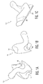
- the envisioned faceplate placement protocols use impression features obtained from a mold 10 ( Figures 1A-1C ) of the ear canal meatus and external ear.
- PCA principal component analysis
- characteristic features of the impression such as the tragus 18, anti-tragus 14, and anti-helix 26 are clearly demarcated.
- optimization techniques such as genetic algorithm, stochastic optimization, memetic algorithm, and/or general combinatorial optimization algorithms are also key algorithmic candidates for the determination of impression features within wide demographic population.
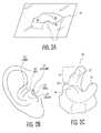
- Figure 2A illustrates definitive landmarks for a datum plane of an impression 10.
- Figures 2B and 2C illustrate corresponding portions of a human ear and impression made therefrom.
- a typical in-the-ear (ITE) hearing instrument comprises the following key electronic components:
- the shell 10' of the hearing aid undergoes a number of manual and labor-intensive operations in a multi-process procedure. These processes occur in order to reduce a raw impression 10 to a prescribed hearing aid instrument.
- One stage of this multi-process procedure is the interactive placement of the faceplate. This is initiated virtually in order to a priori determine whether the prescribed device can be built for the given impression. Furthermore, the final position of the faceplate is considered that which is most optimum, anatomically more comfortable, and collision free (meaning that it does not interfere with electronic components or other parts of the shell).
- All hearing instruments have electronic components, such as batteries, a microphone, a push button(s), a volume control, hybrids, programming contacts, and a faceplate which serves as a carrier for these components. Due to the anatomy of the ear canal, some protruding electronic components, such as the pushbuttons and volume controls, have to be positioned such that they so not come into contact with the patient's ear. Hence significant effort is undertaken during the design phase of the casing of the hearing instrument to ensure that patient comfort is accounted for.
- the present invention is directed to ensuring that the placement of the faceplate and its attendant components are automated to ensure efficiency in the design process, adapting to the anatomical complexity of the patient's ear, and ensuring a collision-free component-shell interaction.
- a method for automatically positioning a faceplate assembly on a hearing instrument shell comprising: automatically determining at least one anatomical feature of the hearing instrument shell based on a 3-D data representation of the shell; automatically determining a position of the faceplate assembly on an outer surface of the hearing aid shell based on the at least one anatomical feature; ensuring that the position of the faceplate assembly does not cause a collision (collision detection) with the hearing instrument shell or other hearing aid components; and outputting the position of the faceplate assembly at an output of a computer.
- faceplate placement protocols of the five key types of in-the-ear instrument are outlined below. Furthermore, algorithm-based protocols that implement this automation will be highlighted for each hearing instrument type.
- An automated method for hearing aid faceplate placement is provided that is implemented with a computer and also, at the same time, takes into account the physiological shape of the ear.
- the computer may be implemented on a general purpose computer having a processor that executes code contained with software modules for implementing the algorithms.
- the computer has a memory for holding the software modules during execution and a permanent storage for storing the software modules when the computer is not powered on .
- the computer has a user interface with an input (e.g., keyboard, mouse), and an output (e.g., display screen).
- the computer itself comprises a network connection and other forms of inputs and outputs.
- the software modules can be stored on a computer readable media.
- the placement and integration of the faceplate is automatically performed.
- Computer software running on a general purpose computer simulates the faceplate placement and ensures that the final position of the faceplate results in the optimal collision free position. Accordingly, the software ensures that the final orientation is based on defined rules for a particular shell type.
- Figures 3A-5B illustrate anatomically aware faceplate orientation and placement during the design of a custom hearing instrument according to different shell 10' types.
- Figures 3A and 3B illustrate a full shell (FS) design 10.1'.
- Figures 4A and 4B illustrate half shell (HS), canal (CA), and mini-canal (MC) designs 10.2'.
- Figures 5A and 5B illustrate a completely-in-canal (CIC) design 10.3'.
- Each of the figures illustrate the location of various features of the hearing aid shell 10. Accordingly, the features of the helix 12, anti-tragus 14, vent 16, tragus 18, microphone 20, crus, 22 and concha bowl 24 can be seen.
- a faceplate and attendant electronic controls orientation implemented according to these embodiments of the invention ensure a comfortable and optimum control.
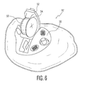
- Figure 6 illustrates a typical semi-modular integrated shell 10' with an opened battery door 52 having a battery 50 in a battery compartment 54.
- the battery door 52 which forms part of the electronic module, is positioned such that it opens away from the tragus 18. But for HS, CA and MC designs 10.2', the battery door 52 is positioned such that it opens towards the tragus 18. In the CIC design 10.3', the battery door 52 is positioned so that it opens away from the vent hole 16. For each of these device types, the determination of the aforementioned landmarks is key to ensuring that the faceplate 30 is anatomically well-positioned.
- the software is designed to ensure that collision detection is facilitated between merge surfaces and the components of the hearing aid.
- An overall flowchart 100 showing the context of the collision detection can be seen in Figure 7 . What is significant here is that such automated placement protocols for hearing instrument faceplate placement is implemented in a 3-dimensional modeling software system.
- 3D data representing the shell is loaded 104 from a database 102.
- the system can receive a file formatted as a Standard Tessellation Language (STL) or 3D-point cloud as input from any of commercially available 3-D scanner systems, such as, Cyberware, Minolta and iSCAN, or in other decodable proprietary and non-proprietary 3D readable format.
- STL Standard Tessellation Language
- 3D-point cloud as input from any of commercially available 3-D scanner systems, such as, Cyberware, Minolta and iSCAN, or in other decodable proprietary and non-proprietary 3D readable format.
- the corresponding faceplate geometry can be provided in STL format as well.
- Vertices of intersecting triangles on the faceplate 60 and the merge surfaces on the shell 10 are computed algorithmically 106.
- Various elements are applied to the design such as the shell wall thickness 108, the vent 110, receiver hole 112, and receiver 114.
- An algorithm may utilize a "collision response", which simply may be likened to a repulsive force that avoids continuous collision between intersecting triangles.
- Such algorithms include close relative distance computation algorithms where intersecting triangles are repulsed.
- traditional collision detection protocols which return a true/false Boolean value as an indication of a geometric interaction of triangles may be utilized for this.
- collision detection algorithms are classified into two distinct groups: a) feature based algorithms, and b) hierarchical bounding volume algorithms. This classification of collision detection protocols is based solely on the distinct advantages and drawbacks associated with each protocol.
- a collision is checked during component placement to ensure that the device size is optimized and the placement of the components do not impact the anatomical structure of the ear impression.
- Feature based algorithms in general, are better suited for exploiting temporal coherence in the model.
- infinitesimal motions of the simulated objects require minimal correction to determine the new closest feature pairs.
- feature based collision protocols the object is generally segmented into points, line segments and facets. Such segmentation ensures that each of these discrete entities can be tagged and monitored with the simulation protocols.
- Hierarchical bounding volume algorithms require miniscule underlying geometric models of the simulating object(s). In general, non-convex objects, polygon soups, are easily handled by hierarchical bounding volume approaches.
- these protocols can implement a configurable penetration index. This index determines:
- the collision check step 116 if a collision is detected, the steps associated with applying the shell wall thickness 108, vent 110, receiver hole 112, and receiver 114 are performed again, and the check 116 is repeated.
- vent and receiver are optimizable parameters that exist within the art today.
- the resolution of these constraints is not the focus here, and any algorithm developed to optimize the faceplate process has to be adaptive enough to resolve these constraints.
- a verification may be performed via a user interface 122.
- the user can manipulate the STL file using an input device such as a mouse, joy stick, spaceball, or the like.
- the initial placement of the faceplate is automatically implemented using feature recognition and the device based rule-based protocols.
- Figure 7 and the above description shows a utilization of the user interface 122 after the later collision check 120, the user interface 122 can clearly be utilized at any stage during the process for either verification or control purposes.
- the implemented collision feedback mechanism can provide a visual indicator on the user interface 122 when a collision is present.
- a collision between the faceplate 30 and electronic components with shell 10 might be displayed in a configurable color that differs from that used for the faceplate 30, other components, and shell 10.
- the color display can be automatically highlighted by the system to show the user where the interaction between the components occur.
- any visual indicia such as shading or other visual attribute, such as flashing, etc. may be utilized.
- the design may be stored 124 in the database 102.
- the user can be provided with a way to select corresponding features on the impression 10 and on the faceplate/electronic module 30. Using the selected landmarks as inputs, the software can then align the faceplate/electronic module 30 with the impression 10. Furthermore, the software can further provide the user with the ability to store the coordinates of the landmark data in the database 102. This stored information can serve as a basis for comparative analysis of the system landmark computations against human assisted data acquisition.
- the software can use definitive features acquired in real time from the specific impression 10. This can be accomplished using techniques, hardware, formulae, and procedures described in co-pending U.S. patent application serial no. 11/612,616 , entitled “Intelligent Modeling Method and System for Earmold Shell and Hearing Aid Design", herein incorporated by reference.
- the system can then define the corresponding datum planes along the faceplate/module 30.
- Figures 3A-5B illustrate a comprehensive overview of the anatomically-aware faceplate placement on the hearing aid instrument for different hearing aid designs.
- the following protocols may be implemented in a three-dimensional geometric-based software system.
- the protocols under this heading relate to ITE hearing instruments.
- This software system should have the capability to execute the following protocols, at least in some combination:
- CIC completely-in-canal
- the present invention may be described in terms of functional block components and various processing steps. Such functional blocks may be realized by any number of hardware and/or software components configured to perform the specified functions.
- the present invention may employ various integrated circuit components, e.g., memory elements, processing elements, logic elements, look-up tables, and the like, which may carry out a variety of functions under the control of one or more microprocessors or other control devices.
- the elements of the present invention are implemented using software programming or software elements the invention may be implemented with any programming or scripting language such as C, C++, Java, assembler, or the like, with the various algorithms being implemented with any combination of data structures, objects, processes, routines or other programming elements.
- the present invention could employ any number of conventional techniques for electronics configuration, signal processing and/or control, data processing and the like.
- the word mechanism is used broadly and is not limited to mechanical or physical embodiments, but can include software routines in conjunction with processors, etc.
Landscapes
- Engineering & Computer Science (AREA)
- Physics & Mathematics (AREA)
- Signal Processing (AREA)
- General Physics & Mathematics (AREA)
- Neurosurgery (AREA)
- Otolaryngology (AREA)
- Health & Medical Sciences (AREA)
- Acoustics & Sound (AREA)
- Manufacturing & Machinery (AREA)
- Theoretical Computer Science (AREA)
- General Health & Medical Sciences (AREA)
- Computing Systems (AREA)
- Mathematical Analysis (AREA)
- Mathematical Optimization (AREA)
- Mathematical Physics (AREA)
- Pure & Applied Mathematics (AREA)
- General Engineering & Computer Science (AREA)
- Computational Mathematics (AREA)
- Stereophonic System (AREA)
Abstract
Description
- The present invention is directed to a method for automating the placement of a faceplate in a hearing instrument using rule-based protocols based on characteristic shell features and collision detection protocols.
- The envisioned faceplate placement protocols use impression features obtained from a mold 10 (
Figures 1A-1C ) of the ear canal meatus and external ear. Using principal component analysis (PCA) techniques, characteristic features of the impression, such as thetragus 18, anti-tragus 14, and anti-helix 26 are clearly demarcated. Furthermore, optimization techniques such as genetic algorithm, stochastic optimization, memetic algorithm, and/or general combinatorial optimization algorithms are also key algorithmic candidates for the determination of impression features within wide demographic population.Figure 2A illustrates definitive landmarks for a datum plane of animpression 10.Figures 2B and 2C illustrate corresponding portions of a human ear and impression made therefrom. - A typical in-the-ear (ITE) hearing instrument comprises the following key electronic components:
- A microphone that picks up the sound and transfers it to the amplifier;
- A receiver that makes the sound louder and to help correct any sound distortion;
- A volume control that adjusts loudness;
- A battery that supplies the power; and
- A push button that toggles between programmed settings.
- In a traditional hearing aid design, the shell 10' of the hearing aid undergoes a number of manual and labor-intensive operations in a multi-process procedure. These processes occur in order to reduce a
raw impression 10 to a prescribed hearing aid instrument. - One stage of this multi-process procedure is the interactive placement of the faceplate. This is initiated virtually in order to a priori determine whether the prescribed device can be built for the given impression. Furthermore, the final position of the faceplate is considered that which is most optimum, anatomically more comfortable, and collision free (meaning that it does not interfere with electronic components or other parts of the shell).
- All hearing instruments have electronic components, such as batteries, a microphone, a push button(s), a volume control, hybrids, programming contacts, and a faceplate which serves as a carrier for these components. Due to the anatomy of the ear canal, some protruding electronic components, such as the pushbuttons and volume controls, have to be positioned such that they so not come into contact with the patient's ear. Hence significant effort is undertaken during the design phase of the casing of the hearing instrument to ensure that patient comfort is accounted for.
- The present invention is directed to ensuring that the placement of the faceplate and its attendant components are automated to ensure efficiency in the design process, adapting to the anatomical complexity of the patient's ear, and ensuring a collision-free component-shell interaction.
- Accordingly, in various embodiments of the invention, a method is provided for automatically positioning a faceplate assembly on a hearing instrument shell, comprising: automatically determining at least one anatomical feature of the hearing instrument shell based on a 3-D data representation of the shell; automatically determining a position of the faceplate assembly on an outer surface of the hearing aid shell based on the at least one anatomical feature; ensuring that the position of the faceplate assembly does not cause a collision (collision detection) with the hearing instrument shell or other hearing aid components; and outputting the position of the faceplate assembly at an output of a computer.
- To accomplish this, faceplate placement protocols of the five key types of in-the-ear instrument are outlined below. Furthermore, algorithm-based protocols that implement this automation will be highlighted for each hearing instrument type. An automated method for hearing aid faceplate placement is provided that is implemented with a computer and also, at the same time, takes into account the physiological shape of the ear.
- These may be implemented on a general purpose computer having a processor that executes code contained with software modules for implementing the algorithms. The computer has a memory for holding the software modules during execution and a permanent storage for storing the software modules when the computer is not powered on . The computer has a user interface with an input (e.g., keyboard, mouse), and an output (e.g., display screen). The computer itself comprises a network connection and other forms of inputs and outputs. The software modules can be stored on a computer readable media.
- The invention is described in detail below with reference to various preferred embodiments as illustrated in the figures and appertaining following description.
- Figures 1A-C
- are pictorial illustrations of the basic impression feature definitions for a faceplate datum plane;
- Figure 2A
- is a pictorial illustration showing definitive landmarks for a datum plane of an impression;
- Figures 2B & C
- are pictorial illustrations showing the parts of the ear and corresponding parts of the hearing aid impression;
- Figures 3A & B
- are pictorial drawings illustrating faceplate placement in a hearing aid with a full shell (FS) design;
- Figures 4A & B
- are pictorial drawings illustrating faceplate placement in a hearing aid with a half shell (HS), canal (CA), and mini-canal (MC) designs; and
- Figures 5A & B
- are pictorial drawings illustrating faceplate placement in a hearing aid with a completely-in-canal (CIC) design.
- Figure 6
- is a pictorial illustration showing a typical semimodular integrated shell with an opened battery door;
- Figure 7
- is a flowchart illustrating shell design protocols including sequential collision verification, constraint identification, and shell size optimization protocols;
- Figure 8
- is a pictorial illustration showing a hearing instrument impression with a defined datum plane along the tragus, anti-tragus and anti-helix;
- Figure 9
- is a pictorial illustration of a typical hearing instrument electronic module comprising a trimmers, push button, battery door, and defined datum plane;
- Figure 10
- is a pictorial illustration of a scanned electronic module showing key orientation mark points;
- Figure 11
- is a pictorial illustration showing the synchronization of datum planes of the faceplate/electronic and shell impression;
- Figure 12
- is a pictorial illustration of a typical impression with landmark features of hearing instrument;
- Figure 13
- is a pictorial illustration of the relative axis location on the faceplate/electronic module;
- Figure 14
- is a pictorial line drawing illustrating the alignment of datum planes of the faceplate and shell;
- Figure 15
- is a pictorial illustration of a sliced impression and faceplate/electronics showing an elliptic center of the impression and the centroid of the faceplate/electronics;
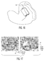
- Figure 16
- is a pictorial illustration of a centerline in a typical ITE hearing aid shell; and
- Figure 17
- is a pictorial illustration showing the reference helix contour/plane.
- According to various embodiments of the invention discussed below, the placement and integration of the faceplate is automatically performed. Computer software running on a general purpose computer simulates the faceplate placement and ensures that the final position of the faceplate results in the optimal collision free position. Accordingly, the software ensures that the final orientation is based on defined rules for a particular shell type.
-
Figures 3A-5B illustrate anatomically aware faceplate orientation and placement during the design of a custom hearing instrument according to different shell 10' types.Figures 3A and 3B illustrate a full shell (FS) design 10.1'.Figures 4A and 4B illustrate half shell (HS), canal (CA), and mini-canal (MC) designs 10.2'. Finally,Figures 5A and 5B illustrate a completely-in-canal (CIC) design 10.3'. Each of the figures illustrate the location of various features of thehearing aid shell 10. Accordingly, the features of thehelix 12,anti-tragus 14, vent 16,tragus 18,microphone 20, crus, 22 andconcha bowl 24 can be seen. A faceplate and attendant electronic controls orientation implemented according to these embodiments of the invention ensure a comfortable and optimum control. -
Figure 6 illustrates a typical semi-modular integrated shell 10' with an openedbattery door 52 having abattery 50 in abattery compartment 54. - For an in-the-ear (ITE) device 10.1', the
battery door 52, which forms part of the electronic module, is positioned such that it opens away from thetragus 18. But for HS, CA and MC designs 10.2', thebattery door 52 is positioned such that it opens towards thetragus 18. In the CIC design 10.3', thebattery door 52 is positioned so that it opens away from thevent hole 16. For each of these device types, the determination of the aforementioned landmarks is key to ensuring that thefaceplate 30 is anatomically well-positioned. - The software is designed to ensure that collision detection is facilitated between merge surfaces and the components of the hearing aid. An
overall flowchart 100 showing the context of the collision detection can be seen inFigure 7 . What is significant here is that such automated placement protocols for hearing instrument faceplate placement is implemented in a 3-dimensional modeling software system. - 3D data representing the shell is loaded 104 from a
database 102. The system can receive a file formatted as a Standard Tessellation Language (STL) or 3D-point cloud as input from any of commercially available 3-D scanner systems, such as, Cyberware, Minolta and iSCAN, or in other decodable proprietary and non-proprietary 3D readable format. Furthermore, the corresponding faceplate geometry can be provided in STL format as well. - Vertices of intersecting triangles on the faceplate 60 and the merge surfaces on the
shell 10 are computed algorithmically 106. Various elements are applied to the design such as theshell wall thickness 108, thevent 110,receiver hole 112, andreceiver 114. - At this point, a
collision check 116 is performed. An algorithm may utilize a "collision response", which simply may be likened to a repulsive force that avoids continuous collision between intersecting triangles. Such algorithms include close relative distance computation algorithms where intersecting triangles are repulsed. Additionally, traditional collision detection protocols, which return a true/false Boolean value as an indication of a geometric interaction of triangles may be utilized for this. - In geometric programming, collision detection algorithms are classified into two distinct groups: a) feature based algorithms, and b) hierarchical bounding volume algorithms. This classification of collision detection protocols is based solely on the distinct advantages and drawbacks associated with each protocol. In hearing instrument design, a collision is checked during component placement to ensure that the device size is optimized and the placement of the components do not impact the anatomical structure of the ear impression.
- Feature based algorithms, in general, are better suited for exploiting temporal coherence in the model. In feature based algorithms, infinitesimal motions of the simulated objects require minimal correction to determine the new closest feature pairs. Furthermore, in feature based collision protocols, the object is generally segmented into points, line segments and facets. Such segmentation ensures that each of these discrete entities can be tagged and monitored with the simulation protocols.
- Hierarchical bounding volume algorithms require miniscule underlying geometric models of the simulating object(s). In general, non-convex objects, polygon soups, are easily handled by hierarchical bounding volume approaches.
- In addition to the standard collision protocols, these protocols can implement a configurable penetration index. This index determines:
- 1. Which electronic components are allowed to interact freely without evoking collision; and
- 2. What penetration depth is allowed between the meshed surfaces of the electronic components before collision detection is triggered.
- In the
collision check step 116, if a collision is detected, the steps associated with applying theshell wall thickness 108, vent 110,receiver hole 112, andreceiver 114 are performed again, and thecheck 116 is repeated. - If there is no collision up to this point, then positioning of the
electronics faceplate 118 is performed, and asubsequent collision check 120 follows. If a collision is detected at this point, then the software repeats the preceding steps from the point of applying the vent 110-118. - Note that the vent and receiver are optimizable parameters that exist within the art today. The resolution of these constraints is not the focus here, and any algorithm developed to optimize the faceplate process has to be adaptive enough to resolve these constraints.
- If there is no collision, then a verification may be performed via a
user interface 122. The user can manipulate the STL file using an input device such as a mouse, joy stick, spaceball, or the like. In a preferred embodiment, the initial placement of the faceplate is automatically implemented using feature recognition and the device based rule-based protocols. However, althoughFigure 7 and the above description shows a utilization of theuser interface 122 after thelater collision check 120, theuser interface 122 can clearly be utilized at any stage during the process for either verification or control purposes. - The implemented collision feedback mechanism can provide a visual indicator on the
user interface 122 when a collision is present. For example, a collision between thefaceplate 30 and electronic components withshell 10 might be displayed in a configurable color that differs from that used for thefaceplate 30, other components, andshell 10. The color display can be automatically highlighted by the system to show the user where the interaction between the components occur. Of course, any visual indicia, such as shading or other visual attribute, such as flashing, etc. may be utilized. - As illustrated in
Figure 7 , when a design has been completed with no collisions amongst the elements, the design may be stored 124 in thedatabase 102. - In the interactive implementation, the user can be provided with a way to select corresponding features on the
impression 10 and on the faceplate/electronic module 30. Using the selected landmarks as inputs, the software can then align the faceplate/electronic module 30 with theimpression 10. Furthermore, the software can further provide the user with the ability to store the coordinates of the landmark data in thedatabase 102. This stored information can serve as a basis for comparative analysis of the system landmark computations against human assisted data acquisition. - In the automated protocols, the software can use definitive features acquired in real time from the
specific impression 10. This can be accomplished using techniques, hardware, formulae, and procedures described in co-pendingU.S. patent application serial no. 11/612,616 , entitled "Intelligent Modeling Method and System for Earmold Shell and Hearing Aid Design", herein incorporated by reference. The system can then define the corresponding datum planes along the faceplate/module 30.Figures 3A-5B illustrate a comprehensive overview of the anatomically-aware faceplate placement on the hearing aid instrument for different hearing aid designs. - To facilitate optimum and
automated faceplate 30 placement on the hollowed end of the shell 10', the following protocols may be implemented in a three-dimensional geometric-based software system. The protocols under this heading relate to ITE hearing instruments. This software system should have the capability to execute the following protocols, at least in some combination: - a) defining a relative coordinate system with origin at the centroid or center of mass of the faceplate/
electronics module 30; - b) generating a shell datum plane 32 (
Figure 8 ) along a hollowed end 28 (Figure 1 B) of theimpression 10 using the focal points of thetragus 18,anti-helix 26, and anti-tragus 14 as reference points for planar definition. - c) generating a corresponding horizontal faceplate assembly datum plane 32' on the faceplate/
electronics module 30 as shown inFigure 9 with the center of the faceplate assembly datum plane 32' at the centroid or center of mass of the faceplate/electronic module 30 assembly. The horizontal faceplate assembly datum plane 32' should be defined along a contour slice 33 (Figure 10 ) of theelectronic module 30 whose center coincides with the centroid of the faceplate/electronic module 30 assembly. The contour slices 33 are defined by planes that are generally perpendicular to a vector that perpendicularly intersects the bottom of thetragus 18 trough. In order to determine the faceplate assembly datum plane 32', using PCA, the variation of the parametric contour sizes is monitored. The first largest contour encountered serves as the basis for the definition of the faceplate/electronic datum plane. In other words, contour areas for contour slices 33 for the faceplate/electronic module 30 are determined atpredefined intervals tragus 18. When aslice 33 is detected having a smaller area than itspredecessor slice 33, then thepredecessor slice 33 is determined to be the first largest contour encountered; - d) automatically aligning the faceplate assembly datum planes 32' of the electronic/
faceplate 30 and theshell datum plane 32 shown inFigure 11 ; - e) ensuring that the X-axis of the faceplate/
electronic module 30 is directed at the trough of thetragus 18; - f) ensuring that the
geometric centerline 35 of the portion of the shell 10' below theaperture 27 and opening out to the external meatus of the impression coincides with the geometric centroid of the faceplate/electronic module 30; and - g) ensuring that the
electronic faceplate module 30 is collision free and furthermore that thebattery 50 does not collide with theconcha peak 21 as shown inFigure 12 .
As illustrated inFigure 15 , thecenterline 35 is not important in the alignment protocols since the center of the plane generated along the anti-helix, tragus and anti-tragus provides the coincident point required to align the centroid of the faceplate/electronics. - For the canal (C), half-shell (HS), and mini-canal (MC) hearing instruments, the steps (a)-(g) described above can be implemented with the following exceptions:
- a) the
centerline 35 of the shell 10' can be computed without thehelix 12 portion. Thecenterline 35 is illustrated inFigure 16 . This section may be eliminated by a cutting plane inserted along thecrus 22 of theimpression 10 as illustrated inFigure 12 andFigure 17; Figure 17 shows animpression 10 with the helix removed. The computation of thecenterline 35 is done as part of the total feature computation of undetailed impression using the same feature set as that of the ITE. In the case of CA, HS and MC when the helix is removed, the centerline is recomputed based on the slicing methodology shown inFigure 16 . Thus, the centerline for these shell types intersects the original anti-tragus, tragus and anti-helix plane defined for the undetailed impression. An elliptic center, which is generally the intersection of the centerline and the based plane (anti-tragus, tragus and anti-helix plane) may be slightly shifted from the elliptic center of the ITE. - b) the final position of the faceplate/
electronic module 30 is rotated 180° along the Z-axis of the faceplate/electronic module 30 (Figure 13 ); and - c) the system ensures that the crus plane defined between the valley of concha and the helix ridge (
Figure 17 ) does not collide with the faceplate geometry by providing a configurable minimum distance of separation. - For the completely-in-canal (CIC) design, the following procedure may be used:
- a) slicing the shell vertically using standard Principal Component Analysis (PCA) protocols (see Alexander Zouhar, Tong Fang, Gozde Unal, Hui Xie, Greg Slabaugh and Fred McBagonluri, Anatomically-aware, Automatic, and Fast Registration of 3D Ear Impression Models, Third International Symposium on 3D Data Processing, Visualization and Transmission, University of North Carolina, Chapel Hill, USA, June 14-16, 2006, herein incorporated by reference).
- b) extracting the largest contour at the hollowed end of the
shell impression 10. In the case of a CIC device, this largest contour is the same as the aperture contour of the impression; - c) computing the
centerline 35 of thecanal 25, which should intersect theaperture 27 plane at the elliptic center of the impression 10 (this is the same as coordinates at the intersection of the major and minor axes of theaperture 27 contour); - d) computing the major and minor axes of the
aperture 27 contour. This is required because the final position of the faceplate/electronic module 30 is along the major axis of theimpression 10. - e) computing the corresponding major and minor axes of the
faceplate 30 geometry, as shown inFigure 14 ; This is computed along the centroid of the faceplate - f) aligning the centroid of the faceplate/
electronic module 30 with the elliptic center of theaperture 27 contour. Note that thecenterline 35 is a key attribute of this computation alignment of the faceplate/electronic module 30 to theimpression 10. It is updated during a transition from one device type to the other for the same impression. This computation allows the elliptic center to be adapted for each device type.
Note that the elliptic center of the impression and the centroid of the faceplate has to be computed as an initial alignment point. Subsequently, as in the case of the CIC the final position of the faceplate/electronics module 30 is along the longest axis of theaperture 27, which is the major axis. The longest axis of the faceplate\electronics module 30 must be aligned along the major axis of theaperture 27 contour. This may require a final rotation about the elliptic center of theimpression 10 which is the principal pivot for the final alignment. - In the above described manner, the correct faceplate placement can ensue for a wide variety of hearing aid shapes in an automated manner. For the purposes of promoting an understanding of the principles of the invention, reference has been made to the preferred embodiments illustrated in the drawings, and specific language has been used to describe these embodiments. However, no limitation of the scope of the invention is intended by this specific language, and the invention should be construed to encompass all embodiments that would normally occur to one of ordinary skill in the art.
- The present invention may be described in terms of functional block components and various processing steps. Such functional blocks may be realized by any number of hardware and/or software components configured to perform the specified functions. For example, the present invention may employ various integrated circuit components, e.g., memory elements, processing elements, logic elements, look-up tables, and the like, which may carry out a variety of functions under the control of one or more microprocessors or other control devices. Similarly, where the elements of the present invention are implemented using software programming or software elements the invention may be implemented with any programming or scripting language such as C, C++, Java, assembler, or the like, with the various algorithms being implemented with any combination of data structures, objects, processes, routines or other programming elements. Furthermore, the present invention could employ any number of conventional techniques for electronics configuration, signal processing and/or control, data processing and the like. The word mechanism is used broadly and is not limited to mechanical or physical embodiments, but can include software routines in conjunction with processors, etc.
- The particular implementations shown and described herein are illustrative examples of the invention and are not intended to otherwise limit the scope of the invention in any way. For the sake of brevity, conventional electronics, control systems, software development and other functional aspects of the systems (and components of the individual operating components of the systems) may not be described in detail. Furthermore, the connecting lines, or connectors shown in the various figures presented are intended to represent exemplary functional relationships and/or physical or logical couplings between the various elements. It should be noted that many alternative or additional functional relationships, physical connections or logical connections may be present in a practical device. Moreover, no item or component is essential to the practice of the invention unless the element is specifically described as "essential" or "critical". Numerous modifications and adaptations will be readily apparent to those skilled in this art without departing from the spirit and scope of the present invention.
Claims (20)
- A method for automatically positioning a faceplate assembly on a hearing instrument shell, comprising:automatically determining at least one anatomical feature of the hearing instrument shell based on a 3-D data representation of the shell;automatically determining a position of the faceplate assembly on an outer surface of the hearing aid shell based on the at least one anatomical feature;ensuring that the position of the faceplate assembly does not cause a collision (collision detection) with the hearing instrument shell or other hearing aid components; andoutputting the position of the faceplate assembly at an output of a computer.
- The method according to claim 1, wherein the anatomical feature is selected from the group consisting of a tragus, an anti-tragus, a crux, and a helix.
- The method according to claim 1, further comprising:classifying the hearing instrument shell as being one of: Class A) an in-the-ear (ITE) design; Class B) a canal (C), half-shell (HS) or mini-canal (MC) design; and Class C) completely-in-canal (CIC) design, wherein different sets of placement rules for automatically determining the position of the faceplate assembly are utilized depending on the classification.
- The method according to claim 3, wherein:for a Class A design, the method further comprises:defining a relative coordinate system with its origin at a centroid or center of mass of the faceplate assembly;generating a shell datum plane along its hollow end utilizing the automatically determined anatomical features tragus, anti-helix, and anti-tragus;generating a faceplate assembly datum plane having a point corresponding to the centroid or center of mass of the faceplate assembly;automatically aligning the shell datum plane and the faceplate assembly datum plane;ensuring that an x-axis of the faceplate assembly datum plane is directed at a trough of the tragus;ensuring that a geometric centerline of a portion of the shell below its aperture and opening out to an external meatus of the impression coincides with the geometric centroid of the faceplate assembly;ensuring that the faceplate assembly is collision free;ensuring that a battery does not collide with a concha peak 21 of the shell; andadjusting a position of the faceplate assembly if any collisions are detected.
- The method according to claim 4, wherein generating a faceplate assembly datum plane comprises:defining a horizontal datum plane along a contour slice of the electronics module whose center coincides with a centroid of the faceplate-electronics module assembly.
- The method according to claim 54.1, wherein the contour slice is defined by a plate that is generally perpendicular to a vector that perpendicularly intersects a bottom of a trough of the tragus.
- The method according to claim 54.1, wherein the faceplate assembly data plane is determined, using PCA, monitoring a variation of parametric contour sizes and selecting a first largest contour encountered to serve as a basis for defining the faceplate-electronics datum plane.
- The method according to claim 4, wherein:for a Class B design, the method further comprises:computing the shell centerline without a helix portion by inserting a cutting plane along a crus of the impression;;rotating the faceplate assembly by 180° along a Z-axis of the faceplate assembly for a final position of the faceplate; andensuring that a crus plane defined between a valley of a concha and a helix ridge does not collide with the faceplate assembly geometry by providing a configurable minimum distance of separation.
- The method according to claim 3, wherein:for a Class C design, the method further comprises:slicing the shell vertically using standard Principal Component Analysis (PCA) protocols;extracting a largest contour at a hollowed end of the shell impression;computing a centerline of the canal, which intersects an aperture plane at an elliptic center of the impression 10;computing major and minor axes of the aperture contour;computing a corresponding major and minor axes of the faceplate geometry, along a centroid of the faceplate; andaligning the centroid of the faceplate with the elliptic center of the aperture contour.
- The method according to claim 1, wherein the collision detection comprises:loading 3D data representing the shell from a database, creating a 3D working model;computing vertices of intersecting of intersecting triangles on the faceplate and merge surfaces of the shell;applying elements to the 3D working model;performing a collision check by applying a collision response algorithm.
- The method according to claim 10, wherein the 3D data is formatted as an STL file or a 3D point cloud.
- The method according to claim 10, wherein the elements include shell wall thickness, a vent, a receiver hole, and a receiver.
- The method according to claim 10, wherein the collision check utilizes an algorithm that is either a feature based algorithm or a hierarchical bounding volume algorithm.
- The method according to claim 10, further comprising implementing a configurable penetration index to determine which electronic components are allowed to interact freely without evoking collision, and what penetration depth is allowed between meshed surfaces of electronic components before collision detection is triggered.
- The method according to claim 10, wherein:if there is a detected collision, then reapplying the elements of the 3D working model and re-performing the collision check; andif there is no detected collision, then positioning the electronics faceplate and performing a subsequent collision check.
- The method according to claim 10, further comprising providing a visual indicator on a user interface device if a collision is present.
- The method according to claim 1, further comprising:storing a completed design with no collisions amongst its elements in the database.
- The method according to claim 1, further comprising:acquiring definitive features in real time; andutilizing these features to define corresponding datum planes.
- A computer system for automatically positioning a faceplate assembly on a hearing instrument shell, comprising:a processor for executing software algorithms;an input and an output associated with the processor;a user interface device for accessing the processor;a memory for storing the software algorithms;wherein the software algorithms comprise:an algorithm for automatically determining at least one anatomical feature of the hearing instrument shell based on a 3-D data representation of the shell;an algorithm for automatically determining a position of the faceplate assembly on an outer surface of the hearing aid shell based on the at least one anatomical feature;an algorithm for ensuring that the position of the faceplate assembly does not cause a collision (collision detection) with the hearing instrument shell or other hearing aid components; andan algorithm for outputting the position of the faceplate assembly at an output of a computer.
- A computer readable media comprising software algorithms of computer-readable code that can be executed on a processor, the algorithms comprising:an algorithm for automatically determining at least one anatomical feature of the hearing instrument shell based on a 3-D data representation of the shell;an algorithm for automatically determining a position of the faceplate assembly on an outer surface of the hearing aid shell based on the at least one anatomical feature;an algorithm for ensuring that the position of the faceplate assembly does not cause a collision (collision detection) with the hearing instrument shell or other hearing aid components; andan algorithm for outputting the position of the faceplate assembly at an output of a computer.
Applications Claiming Priority (1)
| Application Number | Priority Date | Filing Date | Title |
|---|---|---|---|
| US11/872,748 US8065118B2 (en) | 2007-10-16 | 2007-10-16 | Method for anatomically aware automatic faceplate placement for hearing instrument design |
Publications (1)
| Publication Number | Publication Date |
|---|---|
| EP2051545A1 true EP2051545A1 (en) | 2009-04-22 |
Family
ID=40219451
Family Applications (1)
| Application Number | Title | Priority Date | Filing Date |
|---|---|---|---|
| EP08166006A Withdrawn EP2051545A1 (en) | 2007-10-16 | 2008-10-07 | Method for anatomically aware automatic faceplate placement protocols for hearing instrument design |
Country Status (2)
| Country | Link |
|---|---|
| US (1) | US8065118B2 (en) |
| EP (1) | EP2051545A1 (en) |
Families Citing this family (9)
| Publication number | Priority date | Publication date | Assignee | Title |
|---|---|---|---|---|
| ES2378060T3 (en) * | 2001-03-02 | 2012-04-04 | 3Shape A/S | Procedure for modeling custom ear pieces |
| US8554350B2 (en) | 2008-10-15 | 2013-10-08 | Personics Holdings Inc. | Device and method to reduce ear wax clogging of acoustic ports, hearing aid sealing system, and feedback reduction system |
| US8554352B2 (en) * | 2009-05-07 | 2013-10-08 | Siemens Hearing Instruments, Inc. | Method of generating an optimized venting channel in a hearing instrument |
| US9479859B2 (en) | 2013-11-18 | 2016-10-25 | 3M Innovative Properties Company | Concha-fit electronic hearing protection device |
| USD719139S1 (en) | 2013-11-18 | 2014-12-09 | 3M Innovative Properties Company | Hearing protector housing |
| USD719549S1 (en) | 2013-11-18 | 2014-12-16 | 3M Innovative Properties Company | Hearing protector windscreen |
| WO2017184731A1 (en) * | 2016-04-19 | 2017-10-26 | Barry Christopher Robert | Human-ear-wearable apparatus, system, and method of operation |
| CN113039814B (en) * | 2018-11-16 | 2022-09-13 | 斯达克实验室公司 | Ear-worn device housing modeling |
| US20250371804A1 (en) * | 2024-05-28 | 2025-12-04 | Starkey Laboratories, Inc. | Evaluation of hearing instrument components |
Citations (5)
| Publication number | Priority date | Publication date | Assignee | Title |
|---|---|---|---|---|
| US612616A (en) | 1898-10-18 | William h | ||
| US20020196954A1 (en) * | 2001-06-22 | 2002-12-26 | Marxen Christopher J. | Modeling and fabrication of three-dimensional irregular surfaces for hearing instruments |
| US20040107080A1 (en) * | 2001-03-02 | 2004-06-03 | Nikolaj Deichmann | Method for modelling customised earpieces |
| WO2004105432A2 (en) * | 2003-05-15 | 2004-12-02 | Siemens Corporate Research, Inc. | Synchronized processing of ear shells for hearing aids |
| EP2048895A1 (en) * | 2007-10-12 | 2009-04-15 | Siemens Hearing Instruments, Inc. | A computerized rule-based binaural modeling system and method for hearing aid design |
Family Cites Families (3)
| Publication number | Priority date | Publication date | Assignee | Title |
|---|---|---|---|---|
| US7050876B1 (en) * | 2000-10-06 | 2006-05-23 | Phonak Ltd. | Manufacturing methods and systems for rapid production of hearing-aid shells |
| US20040071305A1 (en) * | 2001-02-01 | 2004-04-15 | Peter Frederiksen | Faceplate |
| US7605812B2 (en) * | 2006-12-19 | 2009-10-20 | Siemens Aktiengesellschaft | Intelligent modeling method and system for earmold shell and hearing aid design |
-
2007
- 2007-10-16 US US11/872,748 patent/US8065118B2/en active Active
-
2008
- 2008-10-07 EP EP08166006A patent/EP2051545A1/en not_active Withdrawn
Patent Citations (5)
| Publication number | Priority date | Publication date | Assignee | Title |
|---|---|---|---|---|
| US612616A (en) | 1898-10-18 | William h | ||
| US20040107080A1 (en) * | 2001-03-02 | 2004-06-03 | Nikolaj Deichmann | Method for modelling customised earpieces |
| US20020196954A1 (en) * | 2001-06-22 | 2002-12-26 | Marxen Christopher J. | Modeling and fabrication of three-dimensional irregular surfaces for hearing instruments |
| WO2004105432A2 (en) * | 2003-05-15 | 2004-12-02 | Siemens Corporate Research, Inc. | Synchronized processing of ear shells for hearing aids |
| EP2048895A1 (en) * | 2007-10-12 | 2009-04-15 | Siemens Hearing Instruments, Inc. | A computerized rule-based binaural modeling system and method for hearing aid design |
Also Published As
| Publication number | Publication date |
|---|---|
| US8065118B2 (en) | 2011-11-22 |
| US20090099677A1 (en) | 2009-04-16 |
Similar Documents
| Publication | Publication Date | Title |
|---|---|---|
| US8065118B2 (en) | Method for anatomically aware automatic faceplate placement for hearing instrument design | |
| US7447556B2 (en) | System comprising an automated tool and appertaining method for hearing aid design | |
| US8032337B2 (en) | Method for modeling customized earpieces | |
| EP1368986B1 (en) | Method for modelling customised earpieces | |
| US9715562B2 (en) | Methods and systems for ear device design using computerized tomography (CT)-collected anthropomorphic data | |
| EP2834750B1 (en) | Method for estimating the shape of an individual ear | |
| US7801708B2 (en) | Method and apparatus for the rigid and non-rigid registration of 3D shapes | |
| US20020196954A1 (en) | Modeling and fabrication of three-dimensional irregular surfaces for hearing instruments | |
| WO2002080617A3 (en) | Computer aided system for designing a hearing aid housing | |
| DK1898673T3 (en) | Computerized method of compliance with physical limitation in the design of an ITE hearing aid | |
| US8069022B2 (en) | Method and apparatus for the classification of surface features of an ear impression | |
| US11943587B2 (en) | Generating a hearing assistance device shell | |
| US7995817B2 (en) | System and method for the analysis of basic ear canal taxonomy | |
| US20080222564A1 (en) | Hearing Aid Impression Buildability Index Computation Tool | |
| EP4546822A1 (en) | Ear impression triage and identification of anatomical landmarks in human ears | |
| EP2048895B1 (en) | A computerized rule-based binaural modeling system and method for hearing aid design | |
| EP1980965B1 (en) | Computerized automatic wax guard design modeling system and method for hearing instruments | |
| US8005652B2 (en) | Method and apparatus for surface partitioning using geodesic distance | |
| Slabaugh et al. | 3-D shape modeling for hearing aid design [Applications Corner] | |
| US20110289764A1 (en) | Method of Assembling A Hearing Aid | |
| EP2023662A1 (en) | System comprising an automated tool and appertaining method for hearing aid design | |
| EP4002883A1 (en) | Automated sensor position determination for hearing device housing | |
| EP4657892A1 (en) | Evaluation of hearing instrument components | |
| EP4270996A1 (en) | Ear-wearable device modeling | |
| EP4738890A1 (en) | Visualization and suggestion system for custom hearing devices |
Legal Events
| Date | Code | Title | Description |
|---|---|---|---|
| PUAI | Public reference made under article 153(3) epc to a published international application that has entered the european phase |
Free format text: ORIGINAL CODE: 0009012 |
|
| AK | Designated contracting states |
Kind code of ref document: A1 Designated state(s): AT BE BG CH CY CZ DE DK EE ES FI FR GB GR HR HU IE IS IT LI LT LU LV MC MT NL NO PL PT RO SE SI SK TR |
|
| AX | Request for extension of the european patent |
Extension state: AL BA MK RS |
|
| 17P | Request for examination filed |
Effective date: 20090922 |
|
| 17Q | First examination report despatched |
Effective date: 20091015 |
|
| AKX | Designation fees paid |
Designated state(s): AT BE BG CH CY CZ DE DK EE ES FI FR GB GR HR HU IE IS IT LI LT LU LV MC MT NL NO PL PT RO SE SI SK TR |
|
| RAP1 | Party data changed (applicant data changed or rights of an application transferred) |
Owner name: SIVANTOS, INC. |
|
| STAA | Information on the status of an ep patent application or granted ep patent |
Free format text: STATUS: THE APPLICATION IS DEEMED TO BE WITHDRAWN |
|
| 18D | Application deemed to be withdrawn |
Effective date: 20171215 |