EP2051503A2 - Ergonomic configurations for thermal imaging cameras - Google Patents
Ergonomic configurations for thermal imaging cameras Download PDFInfo
- Publication number
- EP2051503A2 EP2051503A2 EP08253377A EP08253377A EP2051503A2 EP 2051503 A2 EP2051503 A2 EP 2051503A2 EP 08253377 A EP08253377 A EP 08253377A EP 08253377 A EP08253377 A EP 08253377A EP 2051503 A2 EP2051503 A2 EP 2051503A2
- Authority
- EP
- European Patent Office
- Prior art keywords
- camera
- housing
- hand
- focusing assembly
- handle portion
- Prior art date
- Legal status (The legal status is an assumption and is not a legal conclusion. Google has not performed a legal analysis and makes no representation as to the accuracy of the status listed.)
- Ceased
Links
- 238000001931 thermography Methods 0.000 title claims abstract description 24
- 210000003811 finger Anatomy 0.000 claims description 45
- 210000003813 thumb Anatomy 0.000 claims description 14
- 230000000284 resting effect Effects 0.000 description 7
- 238000003384 imaging method Methods 0.000 description 6
- 230000005484 gravity Effects 0.000 description 4
- 230000003213 activating effect Effects 0.000 description 2
- 210000004247 hand Anatomy 0.000 description 2
- 238000007689 inspection Methods 0.000 description 2
- 230000003287 optical effect Effects 0.000 description 2
- 230000002441 reversible effect Effects 0.000 description 2
- 230000004913 activation Effects 0.000 description 1
- 238000003331 infrared imaging Methods 0.000 description 1
- 238000002347 injection Methods 0.000 description 1
- 239000007924 injection Substances 0.000 description 1
- 238000000034 method Methods 0.000 description 1
- 238000012986 modification Methods 0.000 description 1
- 230000004048 modification Effects 0.000 description 1
Images


Classifications
-
- G—PHYSICS
- G01—MEASURING; TESTING
- G01J—MEASUREMENT OF INTENSITY, VELOCITY, SPECTRAL CONTENT, POLARISATION, PHASE OR PULSE CHARACTERISTICS OF INFRARED, VISIBLE OR ULTRAVIOLET LIGHT; COLORIMETRY; RADIATION PYROMETRY
- G01J5/00—Radiation pyrometry, e.g. infrared or optical thermometry
- G01J5/02—Constructional details
- G01J5/025—Interfacing a pyrometer to an external device or network; User interface
-
- G—PHYSICS
- G01—MEASURING; TESTING
- G01J—MEASUREMENT OF INTENSITY, VELOCITY, SPECTRAL CONTENT, POLARISATION, PHASE OR PULSE CHARACTERISTICS OF INFRARED, VISIBLE OR ULTRAVIOLET LIGHT; COLORIMETRY; RADIATION PYROMETRY
- G01J5/00—Radiation pyrometry, e.g. infrared or optical thermometry
- G01J5/02—Constructional details
- G01J5/0265—Handheld, portable
-
- G—PHYSICS
- G01—MEASURING; TESTING
- G01J—MEASUREMENT OF INTENSITY, VELOCITY, SPECTRAL CONTENT, POLARISATION, PHASE OR PULSE CHARACTERISTICS OF INFRARED, VISIBLE OR ULTRAVIOLET LIGHT; COLORIMETRY; RADIATION PYROMETRY
- G01J5/00—Radiation pyrometry, e.g. infrared or optical thermometry
- G01J5/02—Constructional details
- G01J5/04—Casings
-
- H—ELECTRICITY
- H04—ELECTRIC COMMUNICATION TECHNIQUE
- H04N—PICTORIAL COMMUNICATION, e.g. TELEVISION
- H04N23/00—Cameras or camera modules comprising electronic image sensors; Control thereof
- H04N23/50—Constructional details
- H04N23/51—Housings
-
- G—PHYSICS
- G01—MEASURING; TESTING
- G01J—MEASUREMENT OF INTENSITY, VELOCITY, SPECTRAL CONTENT, POLARISATION, PHASE OR PULSE CHARACTERISTICS OF INFRARED, VISIBLE OR ULTRAVIOLET LIGHT; COLORIMETRY; RADIATION PYROMETRY
- G01J5/00—Radiation pyrometry, e.g. infrared or optical thermometry
- G01J2005/0077—Imaging
Definitions
- the present disclosure pertains to thermal imaging cameras and more particularly to configurations thereof for handheld operation.
- Handheld thermal imaging cameras for example, including microbolometer detectors to generate infrared images, are used in a variety of applications, which include the inspection of buildings and industrial equipment.
- Many state-of-the-art thermal imaging cameras have a relatively large amount of built-in functionality allowing a user to select a display from among a host of display options, so that the user may maximize his 'real time', or on site, comprehension of the thermal information collected by the camera.
- the user of such a camera is not able to take full advantage of the increased functionality of the camera, for example, when one of the user's hands must be used to stabilize the user at the inspection site and is not available to help hold and/or operate the camera.
- a thermal imaging camera comprising:
- the camera may further comprise a trigger for image capture mounted to the housing beneath the ring of the focusing assembly.
- the trigger may be located for a middle finger of the hand to activate, when the index finger is positioned on the surface of the ring.
- the trigger may be located for either of the index finger and a middle finger of the hand to activate, when the hand is wrapped about the handle portion of the housing such that an area of the hand between a thumb of the hand and the index finger abuts the shoulder of the housing.
- the imaging assembly may be mounted in the camera portion of the housing such that a centre of gravity of the camera is located in proximity to the second axis, between the trigger and the shoulder of the housing.
- the camera may further comprise a display control member mounted to the camera portion of the housing in proximity to the display, the display control member providing for all adjustments of the display and being positioned for a thumb of the hand to activate, when the index finger is positioned on the surface of the ring of the focusing assembly.
- the display control member may comprise a plurality of buttons.
- the surface of the ring of the focusing assembly may extend from a top point thereof, 360° around the first axis.
- a distance that wraps over a surface of the housing from a midpoint of the handle portion to both of a first point on the surface of the ring and a second point on the surface of the ring may be no greater than approximately 4.5 inches.
- the first point can be located between 90° and 180° from the top point of the ring
- the second point can be located between 180° and 270° from the top point of the ring
- the midpoint of the handle can be located beneath the shoulder of the housing.
- the hand can be either a left hand and a right hand.
- a thermal imaging camera comprises:
- the camera may further comprise a trigger for image capture mounted to the housing beneath the ring of the focusing assembly, the trigger being located for a finger of the hand to activate, when the hand is wrapped about the handle portion of the housing.
- the projecting sidewall of the housing may extend between the trigger and the ring of the focusing assembly.
- the camera portion of the housing may further includes a top side, the top side being opposite the bottom side, with the projecting sidewall of the housing extending from the first side of the camera portion and beyond the ring of the focusing assembly in proximity to the top side of the camera portion of the housing.
- the ring of the focusing assembly may include a first edge, in proximity to the first side of the camera portion of the housing, and a second edge, opposite the first edge, and the surface that provides an interface for the index finger extends between the first and second edges, with the projecting sidewall of the housing including a frontal extension extending over the second edge of the ring of the focusing assembly.
- the projecting sidewall may extend from the first side of the camera portion of the housing and beyond the ring of the focusing assembly in proximity to the bottom side of the camera portion, with the camera portion of the housing further including a top side and another projecting sidewall, the top side being opposite the bottom side and the other projecting sidewall of the housing extending from the first side of the camera portion and beyond the ring of the focusing assembly in proximity to the top side of the camera portion of the housing.
- the housing may further include a frontal extension extending between the projecting sidewalls.
- a visible light camera module may be mounted within the projecting sidewall.
- the camera may further comprise a lens cap pivotably mounted to the projecting sidewall of the housing to be opened and closed over the lens of the focusing assembly.
- thermo imaging camera comprising:
- the housing may include a feature to secure the lens cap in an open position, and/or a feature to secure the lens cap in a closed position.
- the camera may further comprise a visible light camera module mounted within the housing, in which case the lens cap may be mounted to also be opened and closed over an aperture for the visible light camera module.
- thermo imaging camera comprising:
- the housing may further include a first shoulder extending under the first side of the camera portion, between the camera portion and the handle portion, and a second shoulder extending under the second side of the camera portion, between the camera portion and the handle portion; and be arranged such that an area of the hand between a thumb of the hand and the index finger abuts the second shoulder of the housing and another finger of the hand abuts the first shoulder of the housing, when the index finger is positioned to activate the focusing assembly and the hand is wrapped about the handle portion of the housing.
- the camera may further comprise a trigger for image capture mounted to the housing beneath the focusing assembly.
- the imaging assembly may be mounted in the camera portion of the housing such that a centre of gravity of the camera is located in proximity to the second axis, between the trigger and the second shoulder of the housing.
- the focusing assembly may include a lens and ring mounted around the lens, the ring having a surface providing an interface for the index finger.
- the housing may further include a projecting sidewall extending from the first side of the camera portion of the housing and beyond the ring of the focusing assembly.
- the camera may include a display mounted to the second side of the camera portion of the housing, with a display control member mounted to the camera portion of the housing in proximity to the display, the display control member being positioned for a thumb of the hand to activate when the index finger of the hand is positioned for activating the focusing assembly and the hand is wrapped about the handle portion of the housing.
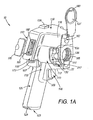
- Figures 1A-B are front and rear perspective views, respectively, of a thermal imaging camera 10, according to some embodiments of the present invention.
- Figures 1A-B illustrate a housing of camera 10, which housing, for example, formed from one or more injection molded, hard plastic parts, provides an ergonomic user interface for various members of camera 10 that lend structural support to all the elements necessary to capture both infrared and visible light images.
- a camera portion 110 of the housing is shown including a first side 111, a second side 112, which is opposite first side 111, a third side 113, a fourth side 114, which is opposite third side 113, a bottom side 115 and a top side 116; and, a handle portion 120 of the housing is shown extending to a terminal end 123 thereof, from bottom side 115 of camera portion 110, and at an angle (angle A, Figure 1C ) away from first side 111 of camera portion 110.
- Figures 1A-B further illustrate a focusing assembly 130, which is mounted to first side 111 of camera portion 110 of the housing, a trigger 140 for image capture, which is mounted to the housing beneath focusing assembly 130, being recessed from first side 111 of camera portion 110 of the housing, and a display 150 along with a display control member 155, which are mounted to second side 112 of camera portion 110 of the housing.
- both focusing assembly 130 and trigger 140 are located with respect to display control member 155 so that, when either a left hand or a right hand is wrapped about handle portion 120 of the housing, an index finger of the hand may reach to activate either focusing assembly 130 or trigger 140 to capture an image, while a thumb of the hand is positioned to activate display control member 155.
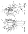
- Figure 1C is a side elevation view of camera 10, according to some embodiments, with portions of the housing removed.
- Figure 1C illustrates a first axis 1, along which camera portion 110 of the housing extends, and a second axis 2, which extends at an angle A, with respect to first axis 1, and along which handle portion 120 of the housing extends, away from first side 111 of camera portion 110.
- angle A is approximately 105 degrees, an angle which facilitates a natural orientation of the hand, when wrapped about handle portion 120, for positioning of the fingers, as described above, and for simultaneous viewing of display 150.
- a viewing surface 151 of display 150 may extend approximately parallel to second axis, in order to facilitate viewing of display 150 when the hand is wrapped about handle portion 120, and a surface 50 of display control member 155 may extend at an angle B with respect to second axis 2, as shown, in order to facilitate depression of member 155 with the thumb of the hand, which is wrapped about handle portion 120.
- Figure 1C further illustrates a thermal imaging assembly 160 mounted within camera portion 110 of the housing, and a visible-light camera module 165 mounted above imaging assembly 160, within an upper projecting sidewall 118 ( Figures 1A-B ) of camera portion 110 of the housing, such that an optical axis thereof is approximately parallel with an optical axis of imaging assembly 160, which approximately coincides with axis 1.
- Upper sidewall 118 is shown extending from first side 111 of camera portion 110 of the housing and over, and, preferably, beyond focusing assembly 135, in proximity to top side 116 camera portion 110.
- the arrangement of elements of imaging assembly 160 and visible-light camera module 165 are such that a center of gravity of camera 10 is located in proximity to axis 2, between trigger 140 and second shoulder 107 of the housing.
- Shoulders 106, 107 are located to provide 'touch points' for the hand of the user, which is wrapped about handle portion 120, for example, as described above, so that the location of the center of gravity and shoulders 106, 107, along with the angling of handle portion 120, can help to balance the camera in a single hand of the user.
- Imaging assembly 160 incorporates those elements, known to those skilled in the art, that are typically necessary for thermal imaging, such as a thermal sensor assembly, for example, a microbolometer thermal detector, a lens assembly and a printed circuit board assembly, for example, including one or more signal processors.
- Visible-light camera module 165 includes similar elements, the sensor assembly of which may be either CMOS or CCD type for digitally capturing images.
- CMOS complementary metal-oxide
- Some exemplary arrangements of infrared imaging assembly elements and visible-light camera elements, which may be employed by embodiments of the present invention, are described in commonly assigned U.S. Patent Application Publication No. US 2006/0249679 ; portions of the detailed description of the '679 reference, which are associated with Figures 3-5 , 7 and 8, are hereby incorporated by reference.
- handle portion 120 of the housing contains a power source, for example, a rechargeable battery, which may be charged via an AC adapter terminal 191, which is shown recessed alongside a memory card slot 192 within camera portion 110 of housing for enclosure via a removable cover 195.
- a power source for example, a rechargeable battery, which may be charged via an AC adapter terminal 191, which is shown recessed alongside a memory card slot 192 within camera portion 110 of housing for enclosure via a removable cover 195.
- focusing assembly 130 includes a ring 135 mounted around a lens 136, and that ring 135 includes an exterior surface 133 extending from a first edge 131, located in proximity to first side 111 of camera portion 110 of the housing, to a second edge 132 of ring 135, wherein surface 133 forms an interface for the index finger to activate focusing assembly 130 by rotating ring 135 to move lens 136 back and forth along axis 1.
- depressions sized to accommodate a tip of an index finger are formed along surface 133.
- Figure 1D is the same side elevation view of camera 10, as that shown in Figure 1C , with some of the removed housing portions replaced; and Figure 1E is a front elevation view of camera 10, with some housing portions removed.
- Figure 1D illustrates focusing assembly 130 located at a first distance D1 from display control member 155, wherein first distance D1 is along first axis 1 and may be between approximately two inches and approximately four inches.
- Figure 1D further illustrates first axis 1 coinciding with a centerline axis of focusing assembly 130, and trigger 140 located at a second distance D2 from first axis 1, wherein second distance D2 is along a line approximately orthogonal to first axis 1 and may be between approximately two inches and approximately three inches.
- Figure 1E illustrates surface 133 of focusing assembly ring 135 extending from a top point 23, 360° around axis 1, and divided into four sectors generally defined between 0° and 90°, between 90° and 180°, between 180° and 270°, and between 270° and 0°.
- a distance D3 which wraps over a surface of the housing from a midpoint 25 of handle portion 120, located just beneath shoulder 107, to a point 26 on ring 135, located in the sector between 90° and 180°, is of a length corresponding to a comfortable reach of an index finger to adjust the focus of camera 10, when the hand of the index finger is wrapped about handle portion 120, for example, as illustrated in Figure 3A .
- distance D3 is no greater than 4.5 inches, which length limitation should accommodate approximately 95% of the hands of the normal adult population.
- Distance D3 may be measured from the length a string which is wrapped over the surface of the housing, for example, as depicted by the dashed line in Figure 1B .
- Figure 1E it should be appreciated that, due to the symmetry of the housing of camera 10, the same distance D3 exists along the opposite side from point 25 to a point 27 which is located on ring 135 in the sector between 180° and 270°.
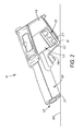
- Figure 2 is a side view of camera 10 resting on a relatively flat surface 200, according to some embodiments.
- Figure 2 illustrates the camera housing further including a first resting edge 21 and a second resting edge 22, which edges 21, 22 form a resting base, or interface, for camera 10 against surface 200.
- First resting edge 21 of the housing is a portion of a perimeter of terminal end 123 of handle portion 120 of the housing
- second resting edge 22 is a corner edge of a projecting sidewall 117 of the housing, which projecting sidewall 117 extends from first side 111 of camera portion 110 of the housing, between focusing assembly 130 and trigger 140.
- Figure 2 further illustrates projecting sidewall 117 including a frontal extension 217, which extension 217 extends over second edge 132 of ring 135 to meet with upper projecting sidewall 118.
- each of projecting sidewall 117, frontal extension 217 and upper sidewall 118 enclose a portion of ring 135 to provide protection for focusing assembly 130, without hampering access to ring surface 133 from either side 113, 114 of camera portion 110 of the housing, thus allowing for either right- or left-handed activation of focusing assembly 130.
- the illustrated combination of projecting sidewall 117, frontal extension 217 and upper sidewall 118 are preferred, alternate embodiments of the present invention may only include one or both of sidewalls 117, 118 extending beyond ring 135 to protect focusing assembly 130.
- Figure 1A illustrates a lens cap 137, which is pivotably mounted to the housing of camera 10 and is opened to expose an aperture 182, for the visible light camera, and lens 136, for the infrared camera, which lens 136 is moveable for focusing, via a ring 135 of focusing assembly 130, as previously described.
- Lens cap 137 is shown coupled to upper sidewall 118, and may be flipped back toward second side 112 of camera portion 110 of the housing and secured in an open position, for example, via a reversible snap fit, by a feature 139 of upper sidewall 118, which feature 139 is shown located in proximity to second side 112 of camera portion 110 of the housing.
- Lens cap 137 is also shown including a projection 183 to mate, for example, via a reversible snap fit, with another feature 185 of the housing, which is formed as a recess in frontal extension 217, in order to secure cap 137 in a closed position over both aperture 182 and lens 136.
- Figure 1B illustrates display 150 including a viewing surface 151, and display control member 155 including a plurality of buttons.
- the buttons of display control member 155 provide for all display adjustments and each button of control member 155 is operated via a thumb T of a hand 300 which is wrapped about handle portion 120 of the housing to hold the camera, for example, in the gripping position illustrated in Figures 3A-B .
- an index finger I of hand 300 which is wrapped about handle portion 120 of the housing of camera 10, may reach to ring 135 in order to focus camera 10.
- Feature 139 of upper sidewall 118 may be used as a sight to help aim camera 10.
- a middle finger M of hand 300 may reach to activate trigger 140, in order to capture an image, while index finger I remains ready to re-focus, if necessary.
- thumb T may activate any of the buttons of display control member 155, to either save or cancel the captured image, which the user sees on viewing surface 151 of display 150. Thumb T may further activate display control member 155 in order to select from a variety of display options, either prior to, or just after, capturing an image. According to some embodiments, activating display control member 155 causes on-screen menus to appear on viewing interface, either alongside or overlaying the captured image, in order to increase the functionality of display control member 155.
- FIG. 3A further illustrates a strap S that provides additional support for a right hand of a user to single-handedly handle and operate camera 10. Strap S is shown having an upper portion coupled to a first strap securing member 173, which is located along camera portion 110 of the housing, and a lower portion coupled to a lower strap securing member 125, which is formed in proximity to terminal end 123 of handle portion 120 of the housing.
- first strap securing member 173 is shown as a loop located on third side 113 of camera portion 110 of the housing.
- a second strap securing member 174 seen in Figures 1B and 1E , is located on fourth side 114 of camera portion 110 of the housing, opposite first strap securing member 173, so that strap S may be coupled to an opposite side of the housing, via second securing member 174 and lower strap securing member 125 of handle portion 120, in order to support left-handed handling and operation, from the opposite side to that shown in Figures 3A-B .
Landscapes
- Physics & Mathematics (AREA)
- General Physics & Mathematics (AREA)
- Spectroscopy & Molecular Physics (AREA)
- Engineering & Computer Science (AREA)
- Multimedia (AREA)
- Signal Processing (AREA)
- Human Computer Interaction (AREA)
- Studio Devices (AREA)
- Camera Bodies And Camera Details Or Accessories (AREA)
Abstract
Description
- The present disclosure pertains to thermal imaging cameras and more particularly to configurations thereof for handheld operation.
- Handheld thermal imaging cameras, for example, including microbolometer detectors to generate infrared images, are used in a variety of applications, which include the inspection of buildings and industrial equipment. Many state-of-the-art thermal imaging cameras have a relatively large amount of built-in functionality allowing a user to select a display from among a host of display options, so that the user may maximize his 'real time', or on site, comprehension of the thermal information collected by the camera. However, in some situations, the user of such a camera is not able to take full advantage of the increased functionality of the camera, for example, when one of the user's hands must be used to stabilize the user at the inspection site and is not available to help hold and/or operate the camera. Thus there is a need for new ergonomic configurations for thermal imaging cameras.
- According to one aspect of the present invention, there is provided a thermal imaging camera comprising:
- a housing including a camera portion extending along a first axis, from a first side of the camera portion to a second side of the camera portion, the second side being opposite the first side, a shoulder extending under the second side of the camera portion, and a handle portion extending from a bottom side of the camera portion to a terminal end of the handle portion, the handle portion further extending away from the first side of the camera portion, along a second axis that is at an angle with respect to the first axis, the handle portion accommodating wrapping of a hand thereabout to support single-handed holding and operation of the camera;
- a thermal imaging assembly mounted within the camera portion of the housing;
- a focusing assembly mounted to the first side of the camera portion of the housing, the focusing assembly including a ring having a surface located to provide an interface for an index finger of the hand, when the hand is wrapped about the handle portion of the housing such that an area of the hand between a thumb of the hand and the index finger abuts the shoulder of the housing; and
- a display mounted to the second side of the camera portion of the housing.
- The camera may further comprise a trigger for image capture mounted to the housing beneath the ring of the focusing assembly. In this case, the trigger may be located for a middle finger of the hand to activate, when the index finger is positioned on the surface of the ring. Alternatively, the trigger may be located for either of the index finger and a middle finger of the hand to activate, when the hand is wrapped about the handle portion of the housing such that an area of the hand between a thumb of the hand and the index finger abuts the shoulder of the housing.
- Where a trigger is provided, the imaging assembly may be mounted in the camera portion of the housing such that a centre of gravity of the camera is located in proximity to the second axis, between the trigger and the shoulder of the housing.
- The camera may further comprise a display control member mounted to the camera portion of the housing in proximity to the display, the display control member providing for all adjustments of the display and being positioned for a thumb of the hand to activate, when the index finger is positioned on the surface of the ring of the focusing assembly. The display control member may comprise a plurality of buttons.
- The surface of the ring of the focusing assembly may extend from a top point thereof, 360° around the first axis. A distance that wraps over a surface of the housing from a midpoint of the handle portion to both of a first point on the surface of the ring and a second point on the surface of the ring may be no greater than approximately 4.5 inches. In this case, the first point can be located between 90° and 180° from the top point of the ring, the second point can be located between 180° and 270° from the top point of the ring, and the midpoint of the handle can be located beneath the shoulder of the housing.
- The hand can be either a left hand and a right hand.
- In accordance with an alternative aspect of the present invention, a thermal imaging camera comprises:
- a housing including a camera portion extending along a first axis, from a first side of the camera portion to a second side of the camera portion, the second side being opposite the first side, a projecting sidewall, and a handle portion extending from a bottom side of the camera portion to a terminal end of the handle portion, the handle portion further extending away from the first side of the camera portion, along a second axis that is at an angle with respect to the first axis, the handle portion accommodating wrapping of a hand thereabout;
- a thermal imaging assembly mounted within the camera portion of the housing; and
- a focusing assembly mounted to the first side of the camera portion of the housing, the focusing assembly including a lens and a ring mounted around the lens, the ring having a surface to provide an interface for an index finger of the hand, when the hand is wrapped about the handle portion of the housing;
- In this case, the camera may further comprise a trigger for image capture mounted to the housing beneath the ring of the focusing assembly, the trigger being located for a finger of the hand to activate, when the hand is wrapped about the handle portion of the housing. The projecting sidewall of the housing may extend between the trigger and the ring of the focusing assembly.
- The camera portion of the housing may further includes a top side, the top side being opposite the bottom side, with the projecting sidewall of the housing extending from the first side of the camera portion and beyond the ring of the focusing assembly in proximity to the top side of the camera portion of the housing.
- The ring of the focusing assembly may include a first edge, in proximity to the first side of the camera portion of the housing, and a second edge, opposite the first edge, and the surface that provides an interface for the index finger extends between the first and second edges, with the projecting sidewall of the housing including a frontal extension extending over the second edge of the ring of the focusing assembly.
- The projecting sidewall may extend from the first side of the camera portion of the housing and beyond the ring of the focusing assembly in proximity to the bottom side of the camera portion, with the camera portion of the housing further including a top side and another projecting sidewall, the top side being opposite the bottom side and the other projecting sidewall of the housing extending from the first side of the camera portion and beyond the ring of the focusing assembly in proximity to the top side of the camera portion of the housing. In this case, the housing may further include a frontal extension extending between the projecting sidewalls.
- A visible light camera module may be mounted within the projecting sidewall.
- The camera may further comprise a lens cap pivotably mounted to the projecting sidewall of the housing to be opened and closed over the lens of the focusing assembly.
- In a still further aspect of the present invention, there is provided a thermal imaging camera comprising:
- a housing including a camera portion extending along a first axis, from a first side of the camera portion to a second side of the camera portion, the second side being opposite the first side, and a handle portion extending from a bottom side of the camera portion to a terminal end of the handle portion, the handle portion further extending away from the first side of the camera portion, along a second axis that is at an angle with respect to the first axis, the handle portion accommodating wrapping of a hand thereabout;
- a thermal imaging assembly mounted within the camera portion of the housing;
- a focusing assembly mounted to the first side of the camera portion of the housing, the focusing assembly including a lens and a ring, the ring having a surface providing an interface for an index finger of the hand, when the hand is wrapped about the handle portion of the housing; and
- a lens cap pivotably mounted to the housing to be opened and closed over the lens of the focusing assembly.
- In this case, the housing may include a feature to secure the lens cap in an open position, and/or a feature to secure the lens cap in a closed position.
- The camera may further comprise a visible light camera module mounted within the housing, in which case the lens cap may be mounted to also be opened and closed over an aperture for the visible light camera module.
- According to a still further aspect of the present invention, there is provided a thermal imaging camera comprising:
- a housing including a camera portion and a handle portion;
- the camera portion including a first side and a second side, between which the camera portion extends along a first axis, the camera portion further including a third side, extending between the first side and the second side, a fourth side, opposite the third side, extending between the first side and the second side, a top side, extending between the first side and the second side, and a bottom side, opposite the top side, extending between the first side and the second side;
- the handle portion extending from the bottom side of the camera portion to a terminal end of the handle portion, the handle portion further extending away from the first side of the camera portion along a second axis that is at an angle with respect to the first axis;
- a thermal imaging assembly mounted within the camera portion of the housing;
- a focusing assembly mounted to the first side of the camera portion of the housing, the focusing assembly being located for an index finger of a hand to activate, when the hand is wrapped about the handle portion of the housing;
- a lower strap securing member located in proximity to the terminal end of the handle portion of the housing;
- a first strap securing member located along the third side of the camera portion of the housing, for use in conjunction with the lower strap securing member in order to reversibly fasten a strap alongside the handle portion; and
- a second strap securing member located along the fourth side of the camera portion of the housing, for use in conjunction with the lower strap securing member in order to reversibly fasten the strap alongside the handle portion.
- In accordance with this aspect, the housing may further include a first shoulder extending under the first side of the camera portion, between the camera portion and the handle portion, and a second shoulder extending under the second side of the camera portion, between the camera portion and the handle portion; and be arranged such that an area of the hand between a thumb of the hand and the index finger abuts the second shoulder of the housing and another finger of the hand abuts the first shoulder of the housing, when the index finger is positioned to activate the focusing assembly and the hand is wrapped about the handle portion of the housing.
- The camera may further comprise a trigger for image capture mounted to the housing beneath the focusing assembly. The imaging assembly may be mounted in the camera portion of the housing such that a centre of gravity of the camera is located in proximity to the second axis, between the trigger and the second shoulder of the housing.
- The focusing assembly may include a lens and ring mounted around the lens, the ring having a surface providing an interface for the index finger. In this case, the housing may further include a projecting sidewall extending from the first side of the camera portion of the housing and beyond the ring of the focusing assembly.
- The camera may include a display mounted to the second side of the camera portion of the housing, with a display control member mounted to the camera portion of the housing in proximity to the display, the display control member being positioned for a thumb of the hand to activate when the index finger of the hand is positioned for activating the focusing assembly and the hand is wrapped about the handle portion of the housing.
- The following drawings are illustrative of particular embodiments of the invention and therefore do not limit the scope of the invention. The drawings are not necessarily to scale (unless so stated) and are intended for use in conjunction with the explanations in the following detailed description. Embodiments of the invention will hereinafter be described in conjunction with the appended drawings, wherein like numerals denote like elements.
-
Figure 1A is a front perspective view of a thermal imaging camera, according to some embodiments of the present invention. -
Figure 1B is a rear perspective view of the camera shown inFigure 1A , according to some embodiments. -
Figure 1C is a side elevation view of the camera shown inFigure 1B , according to some embodiments, with portions of a housing of the camera removed. -
Figure 1D is the same side elevation view ofFigure 1C , with some of the removed housing portions replaced. -
Figure 1E is front elevation view of the camera shown inFigure 1B , with some portions of the housing removed, according to some embodiments. -
Figure 2 is a side view of the camera, shown inFigures 1A-D , resting on a surface, according to some embodiments. -
Figures 3A-B are schematics depicting single handed operation of a thermal imaging camera, according to some embodiments of the present invention. - The following detailed description is exemplary in nature and is not intended to limit the scope, applicability, or configuration of the invention in any way. Rather, the following description provides practical illustrations for implementing exemplary embodiments of the invention.
-
Figures 1A-B are front and rear perspective views, respectively, of athermal imaging camera 10, according to some embodiments of the present invention.Figures 1A-B illustrate a housing ofcamera 10, which housing, for example, formed from one or more injection molded, hard plastic parts, provides an ergonomic user interface for various members ofcamera 10 that lend structural support to all the elements necessary to capture both infrared and visible light images. Acamera portion 110 of the housing is shown including afirst side 111, asecond side 112, which is oppositefirst side 111, athird side 113, afourth side 114, which is oppositethird side 113, abottom side 115 and atop side 116; and, ahandle portion 120 of the housing is shown extending to aterminal end 123 thereof, frombottom side 115 ofcamera portion 110, and at an angle (angle A,Figure 1C ) away fromfirst side 111 ofcamera portion 110.Figures 1A-B further illustrate a focusingassembly 130, which is mounted tofirst side 111 ofcamera portion 110 of the housing, atrigger 140 for image capture, which is mounted to the housing beneath focusingassembly 130, being recessed fromfirst side 111 ofcamera portion 110 of the housing, and adisplay 150 along with adisplay control member 155, which are mounted tosecond side 112 ofcamera portion 110 of the housing. - According to the illustrated embodiment, both focusing
assembly 130 and trigger 140 are located with respect to displaycontrol member 155 so that, when either a left hand or a right hand is wrapped abouthandle portion 120 of the housing, an index finger of the hand may reach to activate either focusingassembly 130 or trigger 140 to capture an image, while a thumb of the hand is positioned to activatedisplay control member 155. With further reference toFigures 1A-B , it should be appreciated that, when either the right or left hand is wrapped as such, another finger of either hand, for example, either a middle finger or a ring finger, abuts afirst shoulder 106 of the housing, which is shown extending underfirst side 111 ofcamera portion 110, just beneathtrigger 140, betweencamera portion 110 and handleportion 120, and an area of the hand between the thumb and the index finger abuts asecond shoulder 107 of the housing, which is shown extending undersecond side 112 ofcamera portion 110, betweencamera portion 110 and handleportion 120. -
Figure 1C is a side elevation view ofcamera 10, according to some embodiments, with portions of the housing removed.Figure 1C illustrates a first axis 1, along whichcamera portion 110 of the housing extends, and asecond axis 2, which extends at an angle A, with respect to first axis 1, and along which handleportion 120 of the housing extends, away fromfirst side 111 ofcamera portion 110. According to some preferred embodiments, angle A is approximately 105 degrees, an angle which facilitates a natural orientation of the hand, when wrapped abouthandle portion 120, for positioning of the fingers, as described above, and for simultaneous viewing ofdisplay 150. Aviewing surface 151 ofdisplay 150 may extend approximately parallel to second axis, in order to facilitate viewing ofdisplay 150 when the hand is wrapped abouthandle portion 120, and asurface 50 ofdisplay control member 155 may extend at an angle B with respect tosecond axis 2, as shown, in order to facilitate depression ofmember 155 with the thumb of the hand, which is wrapped abouthandle portion 120. -
Figure 1C further illustrates athermal imaging assembly 160 mounted withincamera portion 110 of the housing, and a visible-light camera module 165 mounted aboveimaging assembly 160, within an upper projecting sidewall 118 (Figures 1A-B ) ofcamera portion 110 of the housing, such that an optical axis thereof is approximately parallel with an optical axis ofimaging assembly 160, which approximately coincides with axis 1.Upper sidewall 118 is shown extending fromfirst side 111 ofcamera portion 110 of the housing and over, and, preferably, beyond focusingassembly 135, in proximity totop side 116camera portion 110. According to the illustrated embodiment, the arrangement of elements ofimaging assembly 160 and visible-light camera module 165 are such that a center of gravity ofcamera 10 is located in proximity toaxis 2, betweentrigger 140 andsecond shoulder 107 of the housing.Shoulders handle portion 120, for example, as described above, so that the location of the center of gravity and shoulders 106, 107, along with the angling ofhandle portion 120, can help to balance the camera in a single hand of the user. -
Imaging assembly 160 incorporates those elements, known to those skilled in the art, that are typically necessary for thermal imaging, such as a thermal sensor assembly, for example, a microbolometer thermal detector, a lens assembly and a printed circuit board assembly, for example, including one or more signal processors. Visible-light camera module 165 includes similar elements, the sensor assembly of which may be either CMOS or CCD type for digitally capturing images. Some exemplary arrangements of infrared imaging assembly elements and visible-light camera elements, which may be employed by embodiments of the present invention, are described in commonly assigned U.S. Patent Application Publication No.US 2006/0249679 ; portions of the detailed description of the '679 reference, which are associated withFigures 3-5 , 7 and 8, are hereby incorporated by reference. It should be noted thathandle portion 120 of the housing contains a power source, for example, a rechargeable battery, which may be charged via anAC adapter terminal 191, which is shown recessed alongside amemory card slot 192 withincamera portion 110 of housing for enclosure via aremovable cover 195. - With reference to
Figure 1A in conjunction withFigure 1C , it may be appreciated that focusingassembly 130 includes aring 135 mounted around alens 136, and thatring 135 includes anexterior surface 133 extending from afirst edge 131, located in proximity tofirst side 111 ofcamera portion 110 of the housing, to asecond edge 132 ofring 135, whereinsurface 133 forms an interface for the index finger to activate focusingassembly 130 by rotatingring 135 to movelens 136 back and forth along axis 1. According to the illustrated embodiment, depressions sized to accommodate a tip of an index finger are formed alongsurface 133. - Referring now to
Figures 1D-E , and with reference back toFigure 1B , exemplary locations of focusingassembly 130,trigger 140 anddisplay control member 155, which facilitate one-handed operation, will be defined.Figure 1D is the same side elevation view ofcamera 10, as that shown inFigure 1C , with some of the removed housing portions replaced; andFigure 1E is a front elevation view ofcamera 10, with some housing portions removed.Figure 1D illustrates focusingassembly 130 located at a first distance D1 fromdisplay control member 155, wherein first distance D1 is along first axis 1 and may be between approximately two inches and approximately four inches.Figure 1D further illustrates first axis 1 coinciding with a centerline axis of focusingassembly 130, and trigger 140 located at a second distance D2 from first axis 1, wherein second distance D2 is along a line approximately orthogonal to first axis 1 and may be between approximately two inches and approximately three inches.Figure 1E illustratessurface 133 of focusingassembly ring 135 extending from atop point Figures 1B and1D , a distance D3, which wraps over a surface of the housing from amidpoint 25 ofhandle portion 120, located just beneathshoulder 107, to apoint 26 onring 135, located in the sector between 90° and 180°, is of a length corresponding to a comfortable reach of an index finger to adjust the focus ofcamera 10, when the hand of the index finger is wrapped abouthandle portion 120, for example, as illustrated inFigure 3A . According to some preferred embodiments of the present invention, distance D3 is no greater than 4.5 inches, which length limitation should accommodate approximately 95% of the hands of the normal adult population. Distance D3 may be measured from the length a string which is wrapped over the surface of the housing, for example, as depicted by the dashed line inFigure 1B . With further reference toFigure 1E , it should be appreciated that, due to the symmetry of the housing ofcamera 10, the same distance D3 exists along the opposite side frompoint 25 to apoint 27 which is located onring 135 in the sector between 180° and 270°. -
Figure 2 is a side view ofcamera 10 resting on a relativelyflat surface 200, according to some embodiments.Figure 2 illustrates the camera housing further including afirst resting edge 21 and asecond resting edge 22, which edges 21, 22 form a resting base, or interface, forcamera 10 againstsurface 200. First restingedge 21 of the housing is a portion of a perimeter ofterminal end 123 ofhandle portion 120 of the housing, and second restingedge 22 is a corner edge of a projectingsidewall 117 of the housing, which projectingsidewall 117 extends fromfirst side 111 ofcamera portion 110 of the housing, between focusingassembly 130 andtrigger 140.Figure 2 further illustrates projectingsidewall 117 including afrontal extension 217, whichextension 217 extends oversecond edge 132 ofring 135 to meet with upper projectingsidewall 118. With reference back toFigure 1A in conjunction withFigure 2 , it may be appreciated that each of projectingsidewall 117,frontal extension 217 andupper sidewall 118 enclose a portion ofring 135 to provide protection for focusingassembly 130, without hampering access toring surface 133 from eitherside camera portion 110 of the housing, thus allowing for either right- or left-handed activation of focusingassembly 130. Although the illustrated combination of projectingsidewall 117,frontal extension 217 andupper sidewall 118 are preferred, alternate embodiments of the present invention may only include one or both ofsidewalls ring 135 to protect focusingassembly 130. - With reference back to
Figures 1A-B , operation ofcamera 10, according to some methods, will now be described in conjunction with the schematics shown inFigures 3A-B .Figure 1A illustrates alens cap 137, which is pivotably mounted to the housing ofcamera 10 and is opened to expose anaperture 182, for the visible light camera, andlens 136, for the infrared camera, whichlens 136 is moveable for focusing, via aring 135 of focusingassembly 130, as previously described.Lens cap 137 is shown coupled toupper sidewall 118, and may be flipped back towardsecond side 112 ofcamera portion 110 of the housing and secured in an open position, for example, via a reversible snap fit, by afeature 139 ofupper sidewall 118, which feature 139 is shown located in proximity tosecond side 112 ofcamera portion 110 of the housing.Lens cap 137 is also shown including aprojection 183 to mate, for example, via a reversible snap fit, with anotherfeature 185 of the housing, which is formed as a recess infrontal extension 217, in order to securecap 137 in a closed position over bothaperture 182 andlens 136.Figure 1B illustratesdisplay 150 including aviewing surface 151, anddisplay control member 155 including a plurality of buttons. According to some preferred embodiments of the present invention, the buttons ofdisplay control member 155 provide for all display adjustments and each button ofcontrol member 155 is operated via a thumb T of ahand 300 which is wrapped abouthandle portion 120 of the housing to hold the camera, for example, in the gripping position illustrated inFigures 3A-B . - After
camera 10 has been turned on andlens cap 137 flipped open, an index finger I ofhand 300, which is wrapped abouthandle portion 120 of the housing ofcamera 10, may reach to ring 135 in order to focuscamera 10. Feature 139 ofupper sidewall 118 may be used as a sight to help aimcamera 10. According to the schematics ofFigures 3A-B , oncecamera 10 is focused, a middle finger M ofhand 300 may reach to activatetrigger 140, in order to capture an image, while index finger I remains ready to re-focus, if necessary. Although not shown, it should be understood that the grip ofhand 300 may be shifted downward per arrow Y (Figure 3A ) so that middle finger M abutsshoulder 106, rather than a ring finger R ofhand 300; in this case, index finger I may move from focusingassembly ring 135, after focusing, in order to reach down and activatetrigger 140. Once an image is captured, thumb T may activate any of the buttons ofdisplay control member 155, to either save or cancel the captured image, which the user sees onviewing surface 151 ofdisplay 150. Thumb T may further activatedisplay control member 155 in order to select from a variety of display options, either prior to, or just after, capturing an image. According to some embodiments, activatingdisplay control member 155 causes on-screen menus to appear on viewing interface, either alongside or overlaying the captured image, in order to increase the functionality ofdisplay control member 155. - With further reference to
Figures 3A-B , single-handed support ofcamera 10 may be appreciated; an area ofhand 300, which is between thumb T and index finger I, may be seen abuttingsecond shoulder 107, and another finger ofhand 300 may be seen abuttingfirst shoulder 106.Figure 3A further illustrates a strap S that provides additional support for a right hand of a user to single-handedly handle and operatecamera 10. Strap S is shown having an upper portion coupled to a firststrap securing member 173, which is located alongcamera portion 110 of the housing, and a lower portion coupled to a lowerstrap securing member 125, which is formed in proximity toterminal end 123 ofhandle portion 120 of the housing. With reference back toFigures 1A and1E , firststrap securing member 173 is shown as a loop located onthird side 113 ofcamera portion 110 of the housing. According to some preferred embodiments of the present invention, a secondstrap securing member 174, seen inFigures 1B and1E , is located onfourth side 114 ofcamera portion 110 of the housing, opposite firststrap securing member 173, so that strap S may be coupled to an opposite side of the housing, via second securingmember 174 and lowerstrap securing member 125 ofhandle portion 120, in order to support left-handed handling and operation, from the opposite side to that shown inFigures 3A-B . - In the foregoing detailed description, the invention has been described with reference to specific embodiments. However, it may be appreciated that various modifications and changes can be made without departing from the scope of the invention as set forth in the appended claims.
Claims (15)
- A thermal imaging camera comprising:a housing including a camera portion extending along a first axis, from a first side of the camera portion to a second side of the camera portion, the second side being opposite the first side, and a handle portion extending from a bottom side of the camera portion to a terminal end of the handle portion, the handle portion further extending away from the first side of the camera portion, along a second axis that is at an angle with respect to the first axis, the handle portion accommodating wrapping of a hand thereabout;a thermal imaging assembly mounted within the camera portion of the housing; and,a focusing assembly mounted to the first side of the camera portion of the housing, the focusing assembly including a ring, the ring having a surface providing an interface for an index finger of the hand, when the hand is wrapped about the handle portion of the housing.
- The camera of claim 1, further comprising:a shoulder extending under the second side of the camera portion; anda display mounted to the second side of the camera portion of the housing,wherein the handle portion accommodates wrapping of a hand thereabout to support single-handed holding and operation of the camera, and wherein
the hand is wrapped about the handle portion of the housing such that an area of the hand between a thumb of the hand and the index finger abuts the shoulder of the housing. - The camera of claim 2, further comprising a trigger for image capture mounted to the housing beneath the ring of the focusing assembly, the trigger being located for either of the index finger and a middle finger of the hand to activate, when the hand is wrapped about the handle portion of the housing such that an area of the hand between a thumb of the hand and the index finger abuts the shoulder of the housing.
- The camera of claim 2 or claim 3, further comprising a display control member mounted to the camera portion of the housing in proximity to the display, the display control member providing for all adjustments of the display and being positioned for a thumb of the hand to activate, when the index finger is positioned on the surface of the ring of the focusing assembly.
- The camera according to Claim 1, wherein:the housing includes a projecting sidewall extending from the first side of the camera portion of the housing and beyond the ring of the focusing assembly.
- The camera of claim 5, further comprising:a trigger for image capture mounted to the housing beneath the ring of the focusing assembly, the trigger being located for a finger of the hand to activate, when the hand is wrapped about the handle portion of the housing; andwherein the projecting sidewall of the housing extends between the trigger and the ring of the focusing assembly.
- The camera of claim 5, wherein:the camera portion of the housing further includes a top side, the top side being opposite the bottom side; andthe projecting sidewall of the housing extends from the first side of the camera portion and beyond the ring of the focusing assembly in proximity to the top side of the camera portion of the housing.
- The camera of claim 5, wherein:the ring of the focusing assembly includes a first edge, in proximity to the first side of the camera portion of the housing, and a second edge, opposite the first edge, and the surface that provides an interface for the index finger extends between the first and second edges; andthe projecting sidewall of the housing includes a frontal extension extending over the second edge of the ring of the focusing assembly.
- The camera of claim 5, wherein:the projecting sidewall extends from the first side of the camera portion of the housing and beyond the ring of the focusing assembly in proximity to the bottom side of the camera portion;the camera portion of the housing further includes a top side and another projecting sidewall, the top side being opposite the bottom side; andthe other projecting sidewall of the housing extends from the first side of the camera portion and beyond the ring of the focusing assembly in proximity to the top side of the camera portion of the housing.
- The camera of claim 9, wherein the housing further includes a frontal extension extending between the projecting sidewalls.
- The camera of any one of claim 5 to 9, further comprising a visible light camera module mounted within the projecting sidewall.
- The camera of any one of the preceding claims, wherein the focusing assembly further comprises a lens.
- The camera of Claim 12, further comprising a lens cap pivotably mounted to the housing to be opened and closed over the focusing assembly,
wherein the housing optionally includes a feature to secure the lens cap in an open position and/or a closed position. - The camera of claim 13, further comprising a visible light camera module mounted within the housing and wherein the lens cap is mounted to also be opened and closed over an aperture for the visible light camera module.
- A thermal imaging camera comprising:a housing including a camera portion and a handle portion;the camera portion including a first side and a second side, between which the camera portion extends along a first axis, the camera portion further including a third side, extending between the first side and the second side, a fourth side, opposite the third side, extending between the first side and the second side, a top side, extending between the first side and the second side, and a bottom side, opposite the top side, extending between the first side and the second side;the handle portion extending from the bottom side of the camera portion to a terminal end of the handle portion, the handle portion further extending away from the first side of the camera portion along a second axis that is at an angle with respect to the first axis;a thermal imaging assembly mounted within the camera portion of the housing; a focusing assembly mounted to the first side of the camera portion of the housing, the focusing assembly being located for an index finger of a hand to activate, when the hand is wrapped about the handle portion of the housing;a lower strap securing member located in proximity to the terminal end of the handle portion of the housing;a first strap securing member located along the third side of the camera portion of the housing, for use in conjunction with the lower strap securing member in order to reversibly fasten a strap alongside the handle portion; anda second strap securing member located along the fourth side of the camera portion of the housing, for use in conjunction with the lower strap securing member in order to reversibly fasten the strap alongside the handle portion.
Applications Claiming Priority (1)
| Application Number | Priority Date | Filing Date | Title |
|---|---|---|---|
| US11/873,699 US8102424B2 (en) | 2007-10-17 | 2007-10-17 | Ergonomic configurations for thermal imaging cameras |
Publications (2)
| Publication Number | Publication Date |
|---|---|
| EP2051503A2 true EP2051503A2 (en) | 2009-04-22 |
| EP2051503A3 EP2051503A3 (en) | 2013-03-20 |
Family
ID=40298686
Family Applications (1)
| Application Number | Title | Priority Date | Filing Date |
|---|---|---|---|
| EP08253377A Ceased EP2051503A3 (en) | 2007-10-17 | 2008-10-17 | Ergonomic configurations for thermal imaging cameras |
Country Status (3)
| Country | Link |
|---|---|
| US (1) | US8102424B2 (en) |
| EP (1) | EP2051503A3 (en) |
| CN (2) | CN101430227B (en) |
Families Citing this family (25)
| Publication number | Priority date | Publication date | Assignee | Title |
|---|---|---|---|---|
| US9723229B2 (en) * | 2010-08-27 | 2017-08-01 | Milwaukee Electric Tool Corporation | Thermal detection systems, methods, and devices |
| US20120167392A1 (en) * | 2010-12-30 | 2012-07-05 | Stmicroelectronics Pte. Ltd. | Razor with chemical and biological sensor |
| CN203705055U (en) | 2011-03-15 | 2014-07-09 | 米沃奇电动工具公司 | thermal imager |
| US9448198B2 (en) | 2011-07-05 | 2016-09-20 | Stmicroelectronics Pte Ltd. | Microsensor with integrated temperature control |
| US9791896B2 (en) | 2012-07-13 | 2017-10-17 | Symbol Technologies, Llc | Device and method for performing a functionality |
| US9202095B2 (en) | 2012-07-13 | 2015-12-01 | Symbol Technologies, Llc | Pistol grip adapter for mobile device |
| US10794769B2 (en) | 2012-08-02 | 2020-10-06 | Milwaukee Electric Tool Corporation | Thermal detection systems, methods, and devices |
| US9176298B1 (en) | 2012-10-04 | 2015-11-03 | Drs Network & Imaging Systems, Llc | Springless athermal lens design with flexured spacer |
| USD763261S1 (en) * | 2013-04-30 | 2016-08-09 | Symbol Technologies, Llc | Ergonomic mobile computing device |
| USD727393S1 (en) * | 2013-05-30 | 2015-04-21 | Fluke Corporation | Thermal imager |
| USD741390S1 (en) * | 2014-03-10 | 2015-10-20 | Chauvin-Arnoux | Infrared camera in the shape of a gun |
| US20160033336A1 (en) * | 2014-07-30 | 2016-02-04 | Milwaukee Electric Tool Corporation | Thermal detection systems, methods, and devices |
| USD780245S1 (en) * | 2015-06-03 | 2017-02-28 | Flir Systems, Inc. | Camera |
| USD757838S1 (en) * | 2015-06-09 | 2016-05-31 | Fluke Corporatrion | Thermal imager |
| USD807374S1 (en) | 2015-07-21 | 2018-01-09 | Symbol Technologies, Llc | Bezel component for a mobile computer device |
| USD781860S1 (en) | 2015-07-21 | 2017-03-21 | Symbol Technologies, Llc | Mobile computer device |
| USD805571S1 (en) * | 2015-10-01 | 2017-12-19 | Flir Systems Ab | Camera |
| USD805572S1 (en) * | 2015-10-01 | 2017-12-19 | Flir Systems Ab | Camera |
| US9697393B2 (en) | 2015-11-20 | 2017-07-04 | Symbol Technologies, Llc | Methods and systems for adjusting mobile-device operating parameters based on housing-support type |
| US9774767B2 (en) * | 2015-11-29 | 2017-09-26 | Jianhua Cao | Digital memory card window arrangement for IP camera |
| CN107543578A (en) * | 2016-06-24 | 2018-01-05 | 珠海多监测科技有限公司 | A kind of Multifunctional hand-held instrument |
| USD886182S1 (en) * | 2018-06-29 | 2020-06-02 | Qingyuan Chen | Flashlamp for photography |
| US11012596B2 (en) * | 2018-08-29 | 2021-05-18 | Components Express, International | Camera enclosures and end effectors |
| USD918210S1 (en) | 2019-04-04 | 2021-05-04 | Zebra Technologies Corporation | Data capture device |
| US11867559B2 (en) | 2022-04-25 | 2024-01-09 | Snap-On Incorporated | Thermal imager devices |
Citations (1)
| Publication number | Priority date | Publication date | Assignee | Title |
|---|---|---|---|---|
| US20060249679A1 (en) | 2004-12-03 | 2006-11-09 | Johnson Kirk R | Visible light and ir combined image camera |
Family Cites Families (21)
| Publication number | Priority date | Publication date | Assignee | Title |
|---|---|---|---|---|
| US4005605A (en) | 1974-07-22 | 1977-02-01 | Mikron Instrument Company, Inc. | Remote reading infrared thermometer |
| DE2610515C3 (en) * | 1976-03-12 | 1979-01-25 | Agfa-Gevaert Ag, 5090 Leverkusen | Cine film camera with a viewfinder and a handle |
| JPS56501138A (en) | 1979-09-12 | 1981-08-13 | ||
| USD321487S (en) | 1989-04-24 | 1991-11-12 | Diatek Incorporated | Infrared thermometer |
| USD317414S (en) | 1989-05-08 | 1991-06-11 | Ivac Corporation | Handheld infrared thermometer |
| USD348276S (en) | 1991-02-15 | 1994-06-28 | Hastings Phillip W | Combined firearm and long-range camera |
| AU1517000A (en) | 1998-10-26 | 2000-05-15 | Visionary Medical, Inc. | Portable data collection device |
| US6486473B2 (en) | 2000-03-02 | 2002-11-26 | Mine Safety Applicances Company | Thermal imaging camera |
| US6707501B1 (en) * | 2000-06-06 | 2004-03-16 | Tom McKay | Handle control for lens zoom speed control |
| US6440084B1 (en) | 2000-09-14 | 2002-08-27 | Patrick Gentempo | Thermal scanning system and method |
| USD445817S1 (en) | 2001-01-05 | 2001-07-31 | Intel Corporation | Handheld still/video camera |
| USD464666S1 (en) | 2001-02-08 | 2002-10-22 | Mine Safety Appliances Company | Thermal imaging camera |
| USD466540S1 (en) | 2001-05-07 | 2002-12-03 | Flir Systems Ab | Infrared camera |
| CN100414275C (en) * | 2001-05-07 | 2008-08-27 | 前视红外系统股份公司 | Handheld Infrared Camera |
| US6798587B2 (en) | 2002-03-08 | 2004-09-28 | Mikron Infrared, Inc. | Thermal imaging combination and method |
| USD487577S1 (en) | 2003-04-12 | 2004-03-16 | Infrared Solutions, Inc. | Camera |
| USD525640S1 (en) | 2003-05-06 | 2006-07-25 | Infrared Solutions, Inc. | Camera with battery |
| CN2690870Y (en) * | 2004-03-10 | 2005-04-06 | 广州飒特电力红外技术有限公司 | Pistol type double display screen thermal imaging system |
| US7321119B2 (en) * | 2004-08-12 | 2008-01-22 | E.D. Bullard Company | Method and system for thermal imaging having a selective temperature imaging mode |
| USD540838S1 (en) * | 2005-01-13 | 2007-04-17 | Flir Systems Ab | Camera |
| US7541581B2 (en) * | 2005-10-18 | 2009-06-02 | Insight Technology Incorporated | Clip-on infrared imager |
-
2007
- 2007-10-17 US US11/873,699 patent/US8102424B2/en active Active
-
2008
- 2008-10-15 CN CN200810170036.9A patent/CN101430227B/en active Active
- 2008-10-15 CN CN201210097728.1A patent/CN102629980B/en active Active
- 2008-10-17 EP EP08253377A patent/EP2051503A3/en not_active Ceased
Patent Citations (1)
| Publication number | Priority date | Publication date | Assignee | Title |
|---|---|---|---|---|
| US20060249679A1 (en) | 2004-12-03 | 2006-11-09 | Johnson Kirk R | Visible light and ir combined image camera |
Also Published As
| Publication number | Publication date |
|---|---|
| EP2051503A3 (en) | 2013-03-20 |
| CN102629980B (en) | 2015-07-01 |
| US20090102925A1 (en) | 2009-04-23 |
| CN102629980A (en) | 2012-08-08 |
| CN101430227B (en) | 2012-06-13 |
| US8102424B2 (en) | 2012-01-24 |
| CN101430227A (en) | 2009-05-13 |
Similar Documents
| Publication | Publication Date | Title |
|---|---|---|
| US8102424B2 (en) | Ergonomic configurations for thermal imaging cameras | |
| US9606580B2 (en) | Case and mounting apparatus for a tablet computer | |
| EP1956833A1 (en) | Infrared camera | |
| US20140002792A1 (en) | Housing for securing and optically aligning a camera to a scope, a method of attaching said housing, and a kit including said members | |
| KR101053252B1 (en) | Imager | |
| GB2435727A (en) | A handheld viewing device | |
| US7199832B2 (en) | Portable photographic device and grip with integrated controls for single handed use | |
| EP3502951B1 (en) | Ergonomic portable data acquisition terminal | |
| IES20090873A2 (en) | A handheld viewing device | |
| US11886100B2 (en) | Support apparatus for electronic device, and electronic device | |
| US6043503A (en) | Hand held scanning device | |
| US7595837B2 (en) | Image pickup apparatus and grasp member thereof | |
| US20070140684A1 (en) | Case for digital camera | |
| JP2017010712A (en) | Control apparatus and image display system | |
| CN105431774B (en) | Holder for a mobile device for capturing images | |
| JP2003274247A (en) | Imaging device | |
| JPH10210334A (en) | Camera integrated recording device | |
| JP2020177310A (en) | Optical information reading device | |
| JP3216836U (en) | Notebook type mobile terminal case | |
| JP2007173909A (en) | Optical device | |
| JP2003087629A (en) | Digital camera | |
| IE20040400U1 (en) | A viewing device | |
| IES83818Y1 (en) | A viewing device | |
| IE84813B1 (en) | A viewing device | |
| IES85548Y1 (en) | A handheld viewing device |
Legal Events
| Date | Code | Title | Description |
|---|---|---|---|
| PUAI | Public reference made under article 153(3) epc to a published international application that has entered the european phase |
Free format text: ORIGINAL CODE: 0009012 |
|
| AK | Designated contracting states |
Kind code of ref document: A2 Designated state(s): AT BE BG CH CY CZ DE DK EE ES FI FR GB GR HR HU IE IS IT LI LT LU LV MC MT NL NO PL PT RO SE SI SK TR |
|
| AX | Request for extension of the european patent |
Extension state: AL BA MK RS |
|
| PUAL | Search report despatched |
Free format text: ORIGINAL CODE: 0009013 |
|
| RIC1 | Information provided on ipc code assigned before grant |
Ipc: H04N 5/225 20060101AFI20130122BHEP Ipc: H04N 5/33 20060101ALI20130122BHEP |
|
| RIC1 | Information provided on ipc code assigned before grant |
Ipc: H04N 5/225 20060101AFI20130130BHEP Ipc: H04N 5/33 20060101ALI20130130BHEP |
|
| AK | Designated contracting states |
Kind code of ref document: A3 Designated state(s): AT BE BG CH CY CZ DE DK EE ES FI FR GB GR HR HU IE IS IT LI LT LU LV MC MT NL NO PL PT RO SE SI SK TR |
|
| AX | Request for extension of the european patent |
Extension state: AL BA MK RS |
|
| 17P | Request for examination filed |
Effective date: 20130920 |
|
| RBV | Designated contracting states (corrected) |
Designated state(s): AT BE BG CH CY CZ DE DK EE ES FI FR GB GR HR HU IE IS IT LI LT LU LV MC MT NL NO PL PT RO SE SI SK TR |
|
| AKX | Designation fees paid |
Designated state(s): AT BE BG CH CY CZ DE DK EE ES FI FR GB GR HR HU IE IS IT LI LT LU LV MC MT NL NO PL PT RO SE SI SK TR |
|
| 17Q | First examination report despatched |
Effective date: 20140908 |
|
| STAA | Information on the status of an ep patent application or granted ep patent |
Free format text: STATUS: THE APPLICATION HAS BEEN REFUSED |
|
| 18R | Application refused |
Effective date: 20161207 |