EP2051059A2 - Hammer for a Charpy pendulum - Google Patents
Hammer for a Charpy pendulum Download PDFInfo
- Publication number
- EP2051059A2 EP2051059A2 EP08165843A EP08165843A EP2051059A2 EP 2051059 A2 EP2051059 A2 EP 2051059A2 EP 08165843 A EP08165843 A EP 08165843A EP 08165843 A EP08165843 A EP 08165843A EP 2051059 A2 EP2051059 A2 EP 2051059A2
- Authority
- EP
- European Patent Office
- Prior art keywords
- hammer
- weights
- head
- arm
- hammer according
- Prior art date
- Legal status (The legal status is an assumption and is not a legal conclusion. Google has not performed a legal analysis and makes no representation as to the accuracy of the status listed.)
- Granted
Links
Images



Classifications
-
- G—PHYSICS
- G01—MEASURING; TESTING
- G01N—INVESTIGATING OR ANALYSING MATERIALS BY DETERMINING THEIR CHEMICAL OR PHYSICAL PROPERTIES
- G01N3/00—Investigating strength properties of solid materials by application of mechanical stress
- G01N3/30—Investigating strength properties of solid materials by application of mechanical stress by applying a single impulsive force, e.g. by falling weight
-
- G—PHYSICS
- G01—MEASURING; TESTING
- G01N—INVESTIGATING OR ANALYSING MATERIALS BY DETERMINING THEIR CHEMICAL OR PHYSICAL PROPERTIES
- G01N2203/00—Investigating strength properties of solid materials by application of mechanical stress
- G01N2203/003—Generation of the force
- G01N2203/0032—Generation of the force using mechanical means
- G01N2203/0039—Hammer or pendulum
-
- G—PHYSICS
- G01—MEASURING; TESTING
- G01N—INVESTIGATING OR ANALYSING MATERIALS BY DETERMINING THEIR CHEMICAL OR PHYSICAL PROPERTIES
- G01N2203/00—Investigating strength properties of solid materials by application of mechanical stress
- G01N2203/0098—Tests specified by its name, e.g. Charpy, Brinnel, Mullen
Definitions
- the present invention relates in general to equipment for impact tests on plastic materials. More precisely, the invention relates to a hammer for a Charpy pendulum.
- the Charpy pendulum is a measuring instrument that is basically made up of a supporting structure having a rotating shaft with horizontal axis, fixed to which is a hammer that has the purpose of striking a specimen with a preset energy.
- the hammer must be designed and built so as to approximate as accurately as possible the behaviour of an ideal pendulum having an equivalent mass concentrated in the point of impact with the specimen.
- the hammer comprises a metal block fixed to the end of a rod that constitutes the arm of the hammer.
- the traditional solutions derive from the need to position the centre of gravity of the hammer at the point of impact of the head.
- the arm of the hammer is formed by a relatively thin rod with a weight as small as possible with respect to the weight of the head.
- the known solutions involve difficulties from the production standpoint, in particular since they require three different components (the head, the rod, and a device for fixing the rod to the shaft of the pendulum) that must be fixed to one another with high precision.
- the object of the present invention is to provide a hammer for a Charpy pendulum that will be constructively simpler and will have a greater precision than hammers of a known type.
- said object is achieved by a hammer having the characteristics forming the subject of Claim 1.
- the hammer according to the present invention comprises a body including an arm and a head obtained in a monolithic form by means of perimetral cutting of a plane plate.
- the solution according to the present invention enables facilitation of design of the hammer as compared to traditional solutions.
- the hammer according to the present invention is characterized by a high simplicity of fabrication and does not require operations of assembly between the arm and the head.
- the fact of making the arm and the head of the body of the hammer in a monolithic form moreover enables a greater precision to be obtained as compared to the solutions of a known type.
- the new shape of the hammer enables adoption of particularly simple solutions for the application of the weights and for attachment of the hammer to the shaft of the pendulum.
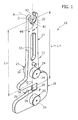
- the hammer 10 comprises a monolithic body 12, in which an arm 14 and a head 16 are defined.
- the body 12 is obtained in a monolithic form by means of perimetral cutting of a plane plate.
- the body 12 can be made of aluminium or alloys thereof, of steel or composite material.
- the perimetral cutting for formation of the body 12 can be obtained by means of any known technology, such as, for example, laser cutting, water cutting, milling, etc.
- the body 12 Since the body 12 is obtained starting from a plane plate, it has two parallel plane faces and has a uniform thickness. In particular, the arm 14 and the head 16 have the same thickness.
- the body 12 has a shape substantially similar to that of a spanner.
- the head 16 has a general C-shape, with a concave part 18 open on one side of the head and closed on three sides.
- the bottom of the concave part 18 defines an area of impact, in which a percussion member 20 is applied.
- the percussion member 20 is, for example, made of steel and can be fixed to the head 16 by means of screws or the like.
- the arm 14 is equipped with an attachment portion 22 located at the end of the arm 14 opposite to the head 16.
- the attachment portion 22 can have a thickness slightly smaller than the thickness of the arm 14.
- Designated by P in Figure 1 is the point of impact with the specimen, and designated by 0 is the centre of rotation of the hammer 10. Moreover designated by A in Figure 1 is the axis of rotation of the hammer 10. The axis A is a horizontal axis that passes through the centre of rotation 0 and is orthogonal to the main plane faces of the body 12.
- L M The distance between the point of impact P and the centre of rotation 0 is designated by L i .
- L M Denoted by L M is the distance of the centre of gravity G of the hammer 10 from the centre of rotation O.
- Lp is the reduced length of the arm of an ideal equivalent pendulum, i.e., a pendulum with a pointlike mass concentrated in a point located at the distance L p from the centre of rotation.
- the hammer 10 is designed and built in such a way that the length L i ( Figure 1 ) is equal to the reduced length L p .
- the hammer 10 is moreover designed in such a way that the nominal energy E n is equal to a pre-set design value.
- the hammer 10 is provided with weights 24, 26, fixed on the opposite faces of the body 12.
- the weights 24, 26 are identical in opposed pairs so as to keep the centre of gravity of the hammer 10 centred on the axis 32.
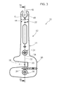
- the body 12 is provided with through holes 28, 30 set in the areas of application of the weights 24, 26.
- the centres of the holes 28, 30 are located on an axis 32 that joins the point of impact P with the centre of rotation O.
- the weights 24, 26 are set on opposite sides with respect to the point of impact P.
- the weights 24 are arranged between the point of impact P and the centre of rotation 0, and the weights 26 are arranged between the point of impact P and the end of the head 16 opposite to the attachment portion 22.
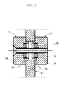
- Each weight 24, 26 comprises a cylindrical hollow casing 34, housed within which are a plurality of commercial metal washers 36.
- the casings 34 couple with the respective hole 28, 30 on the opposite faces of the body 12 and are fixed to one another by means of a screw 38.
- the washers 36 are glued within the respective casings 34.
- the weights 24, 26 are connected to the body 12 in a removable way so that it is possible to replace the weights 24, 26 on the same hammer 10 with others having a different a mass.
- the position of the weights 24, 26 is determined so that, by varying in the same way the mass and the moment of inertia of both of the pairs of weights 24, 26, the reduced length L p remains unvaried. Consequently, it is possible to vary the nominal energy E n of the hammer 10 without varying the length of impact L i .
- the attachment portion 22 comprises a hole 40 orthogonal to the main faces of the body 12 and having an open edge 42.
- the width of the open edge 42 is smaller than the diameter of the hole 40.
- the hole 40 communicates with a positioning notch 44.
- the shaft 46 is carried by the fixed structure of the pendulum (not illustrated) in such a way that it can turn freely about a horizontal axis A.
- the shaft 46 has an attachment portion 48 that is designed to couple with the portion 22 for attachment of the hammer 10.
- the attachment portion 48 of the shaft 46 has a cylindrical shape with a diameter substantially equal to the diameter of the hole 40 and a length slightly smaller than the thickness of the portion 22 for attachment of the hammer 10.
- a shoulder 50 Provided on one side of the attachment portion 48 is a shoulder 50 with a diameter larger than the diameter of the attachment portion 48.
- the attachment portion 48 of the shaft 46 has a small projection 54 that is designed to couple with the positioning notch 44 provided in the portion 22 for attachment of the hammer 10.
- Assembly of the hammer 10 on the shaft 46 is performed by positioning initially the hole of the hammer 10 on the portion of shaft 52 with a small diameter in the direction indicated by the arrow 56 in Figure 6 . Then, the hammer 10 is displaced in an axial direction (in the direction indicated by the arrow 58) for coupling the hole 40 with the attachment portion 48. During this second movement, the hammer 10 is oriented so as to align the notch 44 with the projection 54 in order to obtain a pre-set angular positioning between the hammer 10 and the shaft 46. When the hole 40 of the hammer 10 is coupled with the attachment portion 48 of the shaft 46, the hammer 10 is supported by the shaft 46.
- the blocking member 60 is a fork-shaped wedgelike element that is inserted on the portion with smaller diameter 52 of the shaft 46.
- the blocking member 60 has a wing screw 62 that engages a threaded hole 64 provided in the portion 52 of the shaft 46.
- a transverse pin 66 Provided on the portion of shaft 52 is a transverse pin 66, against which the wedge-shaped part of the blocking member 60 acts.
- the blocking member is inserted in a forced way between the transverse pin 66 and the plane surface of the portion 22 for attachment of the hammer 10, by axially compressing the attachment portion 22 against the shoulder 50 of the shaft 46.
- the fact that the hammer 10 is self-supported also prior to insertion of the blocking member 60 enables screwing of the screw 62 and fixing of the hammer 10 on the shaft 46 in a particularly simple and convenient way.
Landscapes
- Physics & Mathematics (AREA)
- Health & Medical Sciences (AREA)
- Life Sciences & Earth Sciences (AREA)
- Chemical & Material Sciences (AREA)
- Analytical Chemistry (AREA)
- Biochemistry (AREA)
- General Health & Medical Sciences (AREA)
- General Physics & Mathematics (AREA)
- Immunology (AREA)
- Pathology (AREA)
- Percussive Tools And Related Accessories (AREA)
- Crushing And Pulverization Processes (AREA)
- Yarns And Mechanical Finishing Of Yarns Or Ropes (AREA)
Abstract
Description
- The present invention relates in general to equipment for impact tests on plastic materials. More precisely, the invention relates to a hammer for a Charpy pendulum. As is known, the Charpy pendulum is a measuring instrument that is basically made up of a supporting structure having a rotating shaft with horizontal axis, fixed to which is a hammer that has the purpose of striking a specimen with a preset energy. The hammer must be designed and built so as to approximate as accurately as possible the behaviour of an ideal pendulum having an equivalent mass concentrated in the point of impact with the specimen.
- In traditional solutions, the hammer comprises a metal block fixed to the end of a rod that constitutes the arm of the hammer. The traditional solutions derive from the need to position the centre of gravity of the hammer at the point of impact of the head. Traditionally, the arm of the hammer is formed by a relatively thin rod with a weight as small as possible with respect to the weight of the head.
- The known solutions involve difficulties from the production standpoint, in particular since they require three different components (the head, the rod, and a device for fixing the rod to the shaft of the pendulum) that must be fixed to one another with high precision.
- The object of the present invention is to provide a hammer for a Charpy pendulum that will be constructively simpler and will have a greater precision than hammers of a known type.
- According to the present invention, said object is achieved by a hammer having the characteristics forming the subject of
Claim 1. - The hammer according to the present invention comprises a body including an arm and a head obtained in a monolithic form by means of perimetral cutting of a plane plate.
- The solution according to the present invention enables facilitation of design of the hammer as compared to traditional solutions. The hammer according to the present invention is characterized by a high simplicity of fabrication and does not require operations of assembly between the arm and the head. The fact of making the arm and the head of the body of the hammer in a monolithic form moreover enables a greater precision to be obtained as compared to the solutions of a known type. The new shape of the hammer enables adoption of particularly simple solutions for the application of the weights and for attachment of the hammer to the shaft of the pendulum.
- Further characteristics and advantages of the present invention will emerge clearly from the ensuing detailed description, which is provided purely by way of non-limiting example, with reference to the attached drawings, wherein:
-
Figure 1 is a perspective view of a hammer according to the present invention; -
Figure 2 is a partially exploded perspective view of the hammer ofFigure 1 ; -
Figure 3 is a front elevation of the hammer ofFigure 1 ; -
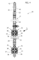
Figure 4 is a cross section according to the line IV-IV ofFigure 3 ; -
Figure 5 is a cross section at a larger scale of the part indicated by the arrow V inFigure 4 ; -
Figure 6 is a perspective view illustrating assembly of the hammer according to the present invention on the shaft of a pendulum; -
Figure 7 is a perspective view at a larger scale of the part indicated by the arrow VII inFigure 6 ; and -
Figure 8 is a partial cross section according to the arrow VIII-VIII ofFigure 7 . - With reference to the drawings, designated by 10 is a hammer for a Charpy pendulum according to the present invention. The
hammer 10 comprises amonolithic body 12, in which anarm 14 and ahead 16 are defined. - According to the present invention, the
body 12 is obtained in a monolithic form by means of perimetral cutting of a plane plate. Thebody 12 can be made of aluminium or alloys thereof, of steel or composite material. The perimetral cutting for formation of thebody 12 can be obtained by means of any known technology, such as, for example, laser cutting, water cutting, milling, etc. - Since the
body 12 is obtained starting from a plane plate, it has two parallel plane faces and has a uniform thickness. In particular, thearm 14 and thehead 16 have the same thickness. - The
body 12 has a shape substantially similar to that of a spanner. Thehead 16 has a general C-shape, with aconcave part 18 open on one side of the head and closed on three sides. The bottom of theconcave part 18 defines an area of impact, in which apercussion member 20 is applied. Thepercussion member 20 is, for example, made of steel and can be fixed to thehead 16 by means of screws or the like. - The
arm 14 is equipped with anattachment portion 22 located at the end of thearm 14 opposite to thehead 16. Theattachment portion 22 can have a thickness slightly smaller than the thickness of thearm 14. - Designated by P in
Figure 1 is the point of impact with the specimen, and designated by 0 is the centre of rotation of thehammer 10. Moreover designated by A inFigure 1 is the axis of rotation of thehammer 10. The axis A is a horizontal axis that passes through the centre ofrotation 0 and is orthogonal to the main plane faces of thebody 12. - The distance between the point of impact P and the centre of
rotation 0 is designated by Li. Denoted by LM is the distance of the centre of gravity G of thehammer 10 from the centre of rotation O. - Defined as Lp is the reduced length of the arm of an ideal equivalent pendulum, i.e., a pendulum with a pointlike mass concentrated in a point located at the distance Lp from the centre of rotation.
- The reduced length of the equivalent ideal pendulum is given by the formula

- The nominal energy of the hammer 10 En is given by the formula

where
I0 is the moment of inertia of thehammer 10 with respect to the axis of rotation A;
M is the overall mass of thehammer 10;
LM is the distance of the centre of gravity G of thehammer 10 from the axis of rotation A;
g is the acceleration of gravity; and
α n is the nominal (pre-set) angle of release of the pendulum. - The
hammer 10 is designed and built in such a way that the length Li (Figure 1 ) is equal to the reduced length Lp. Thehammer 10 is moreover designed in such a way that the nominal energy En is equal to a pre-set design value. - To obtain these conditions, the
hammer 10 is provided withweights body 12. Theweights hammer 10 centred on theaxis 32. - With reference to
Figures 2 ,4 and5 , thebody 12 is provided with throughholes weights holes axis 32 that joins the point of impact P with the centre of rotation O. Theweights weights 24 are arranged between the point of impact P and the centre ofrotation 0, and theweights 26 are arranged between the point of impact P and the end of thehead 16 opposite to theattachment portion 22. Eachweight hollow casing 34, housed within which are a plurality ofcommercial metal washers 36. Thecasings 34 couple with therespective hole body 12 and are fixed to one another by means of ascrew 38. Thewashers 36 are glued within therespective casings 34. - The
weights body 12 in a removable way so that it is possible to replace theweights same hammer 10 with others having a different a mass. The position of theweights weights hammer 10 without varying the length of impact Li. - It is also possible to vary the number of
washers 36, maintaining thecasings 34 unvaried. If the number of the washers is varied in the same way for both pairs ofweights washers 36 in the two pairs ofweights - The flattened shape of the
body 12 enables attachment of thehammer 10 to the rotating shaft of the pendulum in a particularly simple and effective way. According to a preferred embodiment of the present invention, theattachment portion 22 comprises ahole 40 orthogonal to the main faces of thebody 12 and having anopen edge 42. The width of theopen edge 42 is smaller than the diameter of thehole 40. Preferably, thehole 40 communicates with apositioning notch 44. - With reference to
Figure 6 , designated by 46 is the rotating shaft of a Charpy pendulum. Theshaft 46 is carried by the fixed structure of the pendulum (not illustrated) in such a way that it can turn freely about a horizontal axis A. Theshaft 46 has anattachment portion 48 that is designed to couple with theportion 22 for attachment of thehammer 10. Theattachment portion 48 of theshaft 46 has a cylindrical shape with a diameter substantially equal to the diameter of thehole 40 and a length slightly smaller than the thickness of theportion 22 for attachment of thehammer 10. Provided on one side of theattachment portion 48 is ashoulder 50 with a diameter larger than the diameter of theattachment portion 48. Provided on the opposite side of theattachment portion 48 is a portion ofshaft 52 with a diameter smaller than the width of theopen edge 42 of thehammer 10. Theattachment portion 48 of theshaft 46 has asmall projection 54 that is designed to couple with thepositioning notch 44 provided in theportion 22 for attachment of thehammer 10. - Assembly of the
hammer 10 on theshaft 46 is performed by positioning initially the hole of thehammer 10 on the portion ofshaft 52 with a small diameter in the direction indicated by thearrow 56 inFigure 6 . Then, thehammer 10 is displaced in an axial direction (in the direction indicated by the arrow 58) for coupling thehole 40 with theattachment portion 48. During this second movement, thehammer 10 is oriented so as to align thenotch 44 with theprojection 54 in order to obtain a pre-set angular positioning between thehammer 10 and theshaft 46. When thehole 40 of thehammer 10 is coupled with theattachment portion 48 of theshaft 46, thehammer 10 is supported by theshaft 46. Fixing of thehammer 10 is completed by means of a blockingmember 60 that blocks thehammer 10 in an axial direction against theshoulder 50. With reference toFigures 6 ,7 and8 , the blockingmember 60 is a fork-shaped wedgelike element that is inserted on the portion withsmaller diameter 52 of theshaft 46. The blockingmember 60 has awing screw 62 that engages a threadedhole 64 provided in theportion 52 of theshaft 46. Provided on the portion ofshaft 52 is atransverse pin 66, against which the wedge-shaped part of the blockingmember 60 acts. It will be appreciated that by screwing thescrew 62 in thehole 64, the blocking member is inserted in a forced way between thetransverse pin 66 and the plane surface of theportion 22 for attachment of thehammer 10, by axially compressing theattachment portion 22 against theshoulder 50 of theshaft 46. The fact that thehammer 10 is self-supported also prior to insertion of the blockingmember 60 enables screwing of thescrew 62 and fixing of thehammer 10 on theshaft 46 in a particularly simple and convenient way.
Claims (9)
- A hammer for a Charpy pendulum, comprising a body (12) including a head (16) and an arm (14), wherein the arm (14) is equipped with a portion (22) for attachment to an end opposite to that of the head (16) and wherein the head (16) has a general C-shape, with a concave part (18) situated in which is an area of impact, said hammer being characterized in that the arm (14) and the head (16) of said body (12) are obtained in a monolithic form by means of perimetral cutting of a plane plate.
- The hammer according to Claim 1, characterized in that applied in said area of impact is a percussion member (20).
- The hammer according to Claim 1 or Claim 2, characterized in that it comprises a plurality of weights (24, 26) applied on opposite faces of the body (12).
- The hammer according to Claim 3, characterized in that it comprises a first pair of weights (24) and a second pair of weights (26), wherein the weights (24, 26) have a mass and dimensions substantially equal to one another.
- The hammer according to Claim 4, characterized in that the weights (24, 26) are positioned on the body (12) so that by varying the mass and the moment of inertia of the weights (24, 26) in a way equal to one another it is possible to vary the nominal energy (En) of the hammer (10) maintaining the reduced length (Lp) of the hammer (10) unaltered.
- The hammer according to Claim 3, characterized in that the weights (24, 26) can be varied in pairs to calibrate the reduced length (Lp) and the nominal energy (En) of the hammer (10).
- The hammer according to any one of Claims 3-6, characterized in that each of said weights (24, 26) comprises a hollow casing (34), housed within which are a plurality of washers (36) of a commercial type, the number of which can be varied in order to vary the mass of the weights (24, 26).
- The hammer according to Claim 1, characterized in that said attachment section (22) comprises a through hole (40) with an open edge (42) having a width smaller than the diameter of the hole (40).
- The hammer according to Claim 8, characterized in that it comprises a wedge-shaped blocking member (60) designed to block said attachment portion (22) axially.
Applications Claiming Priority (1)
| Application Number | Priority Date | Filing Date | Title |
|---|---|---|---|
| IT000730A ITTO20070730A1 (en) | 2007-10-17 | 2007-10-17 | POKER FOR A PENDULUM OF CHARPY |
Publications (3)
| Publication Number | Publication Date |
|---|---|
| EP2051059A2 true EP2051059A2 (en) | 2009-04-22 |
| EP2051059A3 EP2051059A3 (en) | 2014-02-19 |
| EP2051059B1 EP2051059B1 (en) | 2015-08-26 |
Family
ID=40314141
Family Applications (1)
| Application Number | Title | Priority Date | Filing Date |
|---|---|---|---|
| EP08165843.7A Active EP2051059B1 (en) | 2007-10-17 | 2008-10-03 | Hammer for a Charpy pendulum |
Country Status (4)
| Country | Link |
|---|---|
| US (1) | US7726173B2 (en) |
| EP (1) | EP2051059B1 (en) |
| CN (1) | CN101413857B (en) |
| IT (1) | ITTO20070730A1 (en) |
Families Citing this family (2)
| Publication number | Priority date | Publication date | Assignee | Title |
|---|---|---|---|---|
| WO2018106768A1 (en) | 2016-12-07 | 2018-06-14 | Mts Systems Corporation | Impact sensor body having flexure member |
| BR102022012957A2 (en) | 2022-06-29 | 2024-01-09 | Petróleo Brasileiro S.A. - Petrobras | INSTRUMENTED PENDULUM FOR MINIATURIZED CHARPY IMPACT TESTING AND CHARPY IMPACT MACHINE COMPRISING THE INSTRUMENTED PENDULUM |
Family Cites Families (12)
| Publication number | Priority date | Publication date | Assignee | Title |
|---|---|---|---|---|
| GB257066A (en) * | 1925-07-14 | 1926-08-26 | Adolph Louis Haas | Improved apparatus for testing sheet metal |
| US2359044A (en) * | 1941-04-26 | 1944-09-26 | Tinius Olsen Testing Mach Co | Impact tester |
| US2757694A (en) * | 1954-01-28 | 1956-08-07 | Cecil M Curtis | Shock resisting hammer |
| US2934049A (en) * | 1957-02-26 | 1960-04-26 | Link Belt Speeder Corp | Diesel power hammer |
| US3289470A (en) * | 1963-11-29 | 1966-12-06 | Kimberly Clark Co | Paper testing machine |
| DE2045231A1 (en) * | 1970-09-12 | 1972-03-16 | Mohr & Federhaff Ag | Height difference transmitter for pendulum impact testers |
| US3999420A (en) * | 1975-02-26 | 1976-12-28 | Wright John F | Lens impact hammer apparatus and methods |
| DE3309952C2 (en) * | 1983-03-19 | 1985-10-03 | Bundesrepublik Deutschland, vertreten durch den Bundesminister für Wirtschaft in Bonn, dieser vertreten durch den Präsidenten der Bundesanstalt für Materialprüfung (BAM), 1000 Berlin | C-shaped hammer blade for pendulum hammers |
| US4660832A (en) * | 1985-03-25 | 1987-04-28 | Shomo Robert D | Shock and vibration absorbent handle |
| US7051390B2 (en) * | 2004-02-11 | 2006-05-30 | Van Beek Gys | Multi-purpose tool |
| CN2750304Y (en) * | 2004-07-20 | 2006-01-04 | 甄业盛 | Pendulum impact tester |
| US20070289760A1 (en) * | 2006-06-16 | 2007-12-20 | Exhaust Technologies, Inc. | Shock attenuating coupling device and rotary impact tool |
-
2007
- 2007-10-17 IT IT000730A patent/ITTO20070730A1/en unknown
-
2008
- 2008-10-03 EP EP08165843.7A patent/EP2051059B1/en active Active
- 2008-10-16 US US12/253,055 patent/US7726173B2/en active Active
- 2008-10-17 CN CN2008101697845A patent/CN101413857B/en active Active
Also Published As
| Publication number | Publication date |
|---|---|
| ITTO20070730A1 (en) | 2009-04-18 |
| EP2051059A3 (en) | 2014-02-19 |
| CN101413857B (en) | 2013-11-20 |
| EP2051059B1 (en) | 2015-08-26 |
| US20090100904A1 (en) | 2009-04-23 |
| US7726173B2 (en) | 2010-06-01 |
| CN101413857A (en) | 2009-04-22 |
Similar Documents
| Publication | Publication Date | Title |
|---|---|---|
| US7261641B2 (en) | Method and apparatus for improving dynamic response of golf club | |
| KR101888018B1 (en) | Location Maker For Rebound Hardness Tester | |
| US5454175A (en) | Internal caliper | |
| EP2051059B1 (en) | Hammer for a Charpy pendulum | |
| US20030148819A1 (en) | Method and apparatus for improving dynamic response of golf club | |
| CN116818563B (en) | An experimental device based on Hopkinson rod | |
| CN109323834A (en) | A six-dimensional dynamic force generating device | |
| GB2398035A (en) | Cutting apparatus | |
| ES2975066T3 (en) | Jig assembly comprising a bending jig, and an apparatus and method for measuring bending tensile strength using the same | |
| US20040147339A1 (en) | Apparatus for improving dynamic response of sports implement | |
| US7513060B2 (en) | Loft and lie measurement tool for golf clubs | |
| WO2009021278A1 (en) | A tool | |
| Zhang et al. | Impact strength measurement of spot welds | |
| BR102022012957A2 (en) | INSTRUMENTED PENDULUM FOR MINIATURIZED CHARPY IMPACT TESTING AND CHARPY IMPACT MACHINE COMPRISING THE INSTRUMENTED PENDULUM | |
| WO2016037724A1 (en) | Method for mounting a pendulum laser device | |
| GB2479971A (en) | Measuring device for external diameters | |
| Mugenyi | IZOD Impact strength test device | |
| JP7570071B2 (en) | Adjustment set | |
| CN220945000U (en) | A Charpy pendulum impact specimen assembly tool | |
| CN210513975U (en) | Force hammer fixing tool and modal testing equipment | |
| EP4098997A1 (en) | Process and apparatus for determining the energy release rate of a test piece | |
| US3200639A (en) | Hardness tester | |
| KR20090014786A (en) | Retainer Bar Marking and Accuracy Jig | |
| RU163680U1 (en) | Exciter Not Attachable to Construction | |
| RU2411495C2 (en) | Pocket hardness gauge by kolesnikov |
Legal Events
| Date | Code | Title | Description |
|---|---|---|---|
| PUAI | Public reference made under article 153(3) epc to a published international application that has entered the european phase |
Free format text: ORIGINAL CODE: 0009012 |
|
| AK | Designated contracting states |
Kind code of ref document: A2 Designated state(s): AT BE BG CH CY CZ DE DK EE ES FI FR GB GR HR HU IE IS IT LI LT LU LV MC MT NL NO PL PT RO SE SI SK TR |
|
| AX | Request for extension of the european patent |
Extension state: AL BA MK RS |
|
| RAP1 | Party data changed (applicant data changed or rights of an application transferred) |
Owner name: ILLINOIS TOOL WORKS, INC. |
|
| PUAL | Search report despatched |
Free format text: ORIGINAL CODE: 0009013 |
|
| AK | Designated contracting states |
Kind code of ref document: A3 Designated state(s): AT BE BG CH CY CZ DE DK EE ES FI FR GB GR HR HU IE IS IT LI LT LU LV MC MT NL NO PL PT RO SE SI SK TR |
|
| AX | Request for extension of the european patent |
Extension state: AL BA MK RS |
|
| RIC1 | Information provided on ipc code assigned before grant |
Ipc: G01N 3/00 20060101AFI20140114BHEP |
|
| RAP1 | Party data changed (applicant data changed or rights of an application transferred) |
Owner name: ILLINOIS TOOL WORKS INC. |
|
| 17P | Request for examination filed |
Effective date: 20140327 |
|
| RBV | Designated contracting states (corrected) |
Designated state(s): AT BE BG CH CY CZ DE DK EE ES FI FR GB GR HR HU IE IS IT LI LT LU LV MC MT NL NO PL PT RO SE SI SK TR |
|
| AKX | Designation fees paid |
Designated state(s): AT BE BG CH CY CZ DE DK EE ES FI FR GB GR HR HU IE IS IT LI LT LU LV MC MT NL NO PL PT RO SE SI SK TR |
|
| 17Q | First examination report despatched |
Effective date: 20141204 |
|
| GRAP | Despatch of communication of intention to grant a patent |
Free format text: ORIGINAL CODE: EPIDOSNIGR1 |
|
| INTG | Intention to grant announced |
Effective date: 20150330 |
|
| GRAS | Grant fee paid |
Free format text: ORIGINAL CODE: EPIDOSNIGR3 |
|
| GRAA | (expected) grant |
Free format text: ORIGINAL CODE: 0009210 |
|
| AK | Designated contracting states |
Kind code of ref document: B1 Designated state(s): AT BE BG CH CY CZ DE DK EE ES FI FR GB GR HR HU IE IS IT LI LT LU LV MC MT NL NO PL PT RO SE SI SK TR |
|
| REG | Reference to a national code |
Ref country code: GB Ref legal event code: FG4D |
|
| REG | Reference to a national code |
Ref country code: CH Ref legal event code: EP |
|
| REG | Reference to a national code |
Ref country code: AT Ref legal event code: REF Ref document number: 745467 Country of ref document: AT Kind code of ref document: T Effective date: 20150915 |
|
| REG | Reference to a national code |
Ref country code: IE Ref legal event code: FG4D |
|
| REG | Reference to a national code |
Ref country code: DE Ref legal event code: R096 Ref document number: 602008039757 Country of ref document: DE |
|
| REG | Reference to a national code |
Ref country code: FR Ref legal event code: PLFP Year of fee payment: 8 |
|
| REG | Reference to a national code |
Ref country code: AT Ref legal event code: MK05 Ref document number: 745467 Country of ref document: AT Kind code of ref document: T Effective date: 20150826 |
|
| REG | Reference to a national code |
Ref country code: LT Ref legal event code: MG4D |
|
| PG25 | Lapsed in a contracting state [announced via postgrant information from national office to epo] |
Ref country code: GR Free format text: LAPSE BECAUSE OF FAILURE TO SUBMIT A TRANSLATION OF THE DESCRIPTION OR TO PAY THE FEE WITHIN THE PRESCRIBED TIME-LIMIT Effective date: 20151127 Ref country code: NO Free format text: LAPSE BECAUSE OF FAILURE TO SUBMIT A TRANSLATION OF THE DESCRIPTION OR TO PAY THE FEE WITHIN THE PRESCRIBED TIME-LIMIT Effective date: 20151126 Ref country code: FI Free format text: LAPSE BECAUSE OF FAILURE TO SUBMIT A TRANSLATION OF THE DESCRIPTION OR TO PAY THE FEE WITHIN THE PRESCRIBED TIME-LIMIT Effective date: 20150826 Ref country code: LT Free format text: LAPSE BECAUSE OF FAILURE TO SUBMIT A TRANSLATION OF THE DESCRIPTION OR TO PAY THE FEE WITHIN THE PRESCRIBED TIME-LIMIT Effective date: 20150826 Ref country code: LV Free format text: LAPSE BECAUSE OF FAILURE TO SUBMIT A TRANSLATION OF THE DESCRIPTION OR TO PAY THE FEE WITHIN THE PRESCRIBED TIME-LIMIT Effective date: 20150826 |
|
| REG | Reference to a national code |
Ref country code: NL Ref legal event code: MP Effective date: 20150826 |
|
| PG25 | Lapsed in a contracting state [announced via postgrant information from national office to epo] |
Ref country code: SE Free format text: LAPSE BECAUSE OF FAILURE TO SUBMIT A TRANSLATION OF THE DESCRIPTION OR TO PAY THE FEE WITHIN THE PRESCRIBED TIME-LIMIT Effective date: 20150826 Ref country code: IS Free format text: LAPSE BECAUSE OF FAILURE TO SUBMIT A TRANSLATION OF THE DESCRIPTION OR TO PAY THE FEE WITHIN THE PRESCRIBED TIME-LIMIT Effective date: 20151226 Ref country code: ES Free format text: LAPSE BECAUSE OF FAILURE TO SUBMIT A TRANSLATION OF THE DESCRIPTION OR TO PAY THE FEE WITHIN THE PRESCRIBED TIME-LIMIT Effective date: 20150826 Ref country code: AT Free format text: LAPSE BECAUSE OF FAILURE TO SUBMIT A TRANSLATION OF THE DESCRIPTION OR TO PAY THE FEE WITHIN THE PRESCRIBED TIME-LIMIT Effective date: 20150826 Ref country code: PL Free format text: LAPSE BECAUSE OF FAILURE TO SUBMIT A TRANSLATION OF THE DESCRIPTION OR TO PAY THE FEE WITHIN THE PRESCRIBED TIME-LIMIT Effective date: 20150826 Ref country code: HR Free format text: LAPSE BECAUSE OF FAILURE TO SUBMIT A TRANSLATION OF THE DESCRIPTION OR TO PAY THE FEE WITHIN THE PRESCRIBED TIME-LIMIT Effective date: 20150826 Ref country code: PT Free format text: LAPSE BECAUSE OF FAILURE TO SUBMIT A TRANSLATION OF THE DESCRIPTION OR TO PAY THE FEE WITHIN THE PRESCRIBED TIME-LIMIT Effective date: 20151228 |
|
| PG25 | Lapsed in a contracting state [announced via postgrant information from national office to epo] |
Ref country code: NL Free format text: LAPSE BECAUSE OF FAILURE TO SUBMIT A TRANSLATION OF THE DESCRIPTION OR TO PAY THE FEE WITHIN THE PRESCRIBED TIME-LIMIT Effective date: 20150826 |
|
| PG25 | Lapsed in a contracting state [announced via postgrant information from national office to epo] |
Ref country code: IT Free format text: LAPSE BECAUSE OF FAILURE TO SUBMIT A TRANSLATION OF THE DESCRIPTION OR TO PAY THE FEE WITHIN THE PRESCRIBED TIME-LIMIT Effective date: 20150826 Ref country code: CZ Free format text: LAPSE BECAUSE OF FAILURE TO SUBMIT A TRANSLATION OF THE DESCRIPTION OR TO PAY THE FEE WITHIN THE PRESCRIBED TIME-LIMIT Effective date: 20150826 Ref country code: SK Free format text: LAPSE BECAUSE OF FAILURE TO SUBMIT A TRANSLATION OF THE DESCRIPTION OR TO PAY THE FEE WITHIN THE PRESCRIBED TIME-LIMIT Effective date: 20150826 Ref country code: EE Free format text: LAPSE BECAUSE OF FAILURE TO SUBMIT A TRANSLATION OF THE DESCRIPTION OR TO PAY THE FEE WITHIN THE PRESCRIBED TIME-LIMIT Effective date: 20150826 Ref country code: DK Free format text: LAPSE BECAUSE OF FAILURE TO SUBMIT A TRANSLATION OF THE DESCRIPTION OR TO PAY THE FEE WITHIN THE PRESCRIBED TIME-LIMIT Effective date: 20150826 |
|
| REG | Reference to a national code |
Ref country code: DE Ref legal event code: R097 Ref document number: 602008039757 Country of ref document: DE |
|
| PG25 | Lapsed in a contracting state [announced via postgrant information from national office to epo] |
Ref country code: LU Free format text: LAPSE BECAUSE OF FAILURE TO SUBMIT A TRANSLATION OF THE DESCRIPTION OR TO PAY THE FEE WITHIN THE PRESCRIBED TIME-LIMIT Effective date: 20151003 Ref country code: RO Free format text: LAPSE BECAUSE OF FAILURE TO SUBMIT A TRANSLATION OF THE DESCRIPTION OR TO PAY THE FEE WITHIN THE PRESCRIBED TIME-LIMIT Effective date: 20150826 |
|
| REG | Reference to a national code |
Ref country code: CH Ref legal event code: PL |
|
| PG25 | Lapsed in a contracting state [announced via postgrant information from national office to epo] |
Ref country code: MC Free format text: LAPSE BECAUSE OF FAILURE TO SUBMIT A TRANSLATION OF THE DESCRIPTION OR TO PAY THE FEE WITHIN THE PRESCRIBED TIME-LIMIT Effective date: 20150826 |
|
| PLBE | No opposition filed within time limit |
Free format text: ORIGINAL CODE: 0009261 |
|
| STAA | Information on the status of an ep patent application or granted ep patent |
Free format text: STATUS: NO OPPOSITION FILED WITHIN TIME LIMIT |
|
| REG | Reference to a national code |
Ref country code: IE Ref legal event code: MM4A |
|
| PG25 | Lapsed in a contracting state [announced via postgrant information from national office to epo] |
Ref country code: CH Free format text: LAPSE BECAUSE OF NON-PAYMENT OF DUE FEES Effective date: 20151031 Ref country code: LI Free format text: LAPSE BECAUSE OF NON-PAYMENT OF DUE FEES Effective date: 20151031 |
|
| 26N | No opposition filed |
Effective date: 20160530 |
|
| PG25 | Lapsed in a contracting state [announced via postgrant information from national office to epo] |
Ref country code: SI Free format text: LAPSE BECAUSE OF FAILURE TO SUBMIT A TRANSLATION OF THE DESCRIPTION OR TO PAY THE FEE WITHIN THE PRESCRIBED TIME-LIMIT Effective date: 20150826 |
|
| REG | Reference to a national code |
Ref country code: FR Ref legal event code: PLFP Year of fee payment: 9 |
|
| PG25 | Lapsed in a contracting state [announced via postgrant information from national office to epo] |
Ref country code: IE Free format text: LAPSE BECAUSE OF NON-PAYMENT OF DUE FEES Effective date: 20151003 |
|
| PG25 | Lapsed in a contracting state [announced via postgrant information from national office to epo] |
Ref country code: BE Free format text: LAPSE BECAUSE OF FAILURE TO SUBMIT A TRANSLATION OF THE DESCRIPTION OR TO PAY THE FEE WITHIN THE PRESCRIBED TIME-LIMIT Effective date: 20150826 |
|
| PG25 | Lapsed in a contracting state [announced via postgrant information from national office to epo] |
Ref country code: HU Free format text: LAPSE BECAUSE OF FAILURE TO SUBMIT A TRANSLATION OF THE DESCRIPTION OR TO PAY THE FEE WITHIN THE PRESCRIBED TIME-LIMIT; INVALID AB INITIO Effective date: 20081003 Ref country code: BG Free format text: LAPSE BECAUSE OF FAILURE TO SUBMIT A TRANSLATION OF THE DESCRIPTION OR TO PAY THE FEE WITHIN THE PRESCRIBED TIME-LIMIT Effective date: 20150826 |
|
| PG25 | Lapsed in a contracting state [announced via postgrant information from national office to epo] |
Ref country code: CY Free format text: LAPSE BECAUSE OF FAILURE TO SUBMIT A TRANSLATION OF THE DESCRIPTION OR TO PAY THE FEE WITHIN THE PRESCRIBED TIME-LIMIT Effective date: 20150826 |
|
| PG25 | Lapsed in a contracting state [announced via postgrant information from national office to epo] |
Ref country code: TR Free format text: LAPSE BECAUSE OF FAILURE TO SUBMIT A TRANSLATION OF THE DESCRIPTION OR TO PAY THE FEE WITHIN THE PRESCRIBED TIME-LIMIT Effective date: 20150826 Ref country code: MT Free format text: LAPSE BECAUSE OF FAILURE TO SUBMIT A TRANSLATION OF THE DESCRIPTION OR TO PAY THE FEE WITHIN THE PRESCRIBED TIME-LIMIT Effective date: 20150826 |
|
| REG | Reference to a national code |
Ref country code: FR Ref legal event code: PLFP Year of fee payment: 10 |
|
| REG | Reference to a national code |
Ref country code: FR Ref legal event code: PLFP Year of fee payment: 11 |
|
| P01 | Opt-out of the competence of the unified patent court (upc) registered |
Effective date: 20230606 |
|
| PGFP | Annual fee paid to national office [announced via postgrant information from national office to epo] |
Ref country code: DE Payment date: 20251029 Year of fee payment: 18 |
|
| PGFP | Annual fee paid to national office [announced via postgrant information from national office to epo] |
Ref country code: GB Payment date: 20251027 Year of fee payment: 18 |
|
| PGFP | Annual fee paid to national office [announced via postgrant information from national office to epo] |
Ref country code: FR Payment date: 20251027 Year of fee payment: 18 |