EP2050949A1 - Device for swirling and mixing exhaust gases - Google Patents
Device for swirling and mixing exhaust gases Download PDFInfo
- Publication number
- EP2050949A1 EP2050949A1 EP08164887A EP08164887A EP2050949A1 EP 2050949 A1 EP2050949 A1 EP 2050949A1 EP 08164887 A EP08164887 A EP 08164887A EP 08164887 A EP08164887 A EP 08164887A EP 2050949 A1 EP2050949 A1 EP 2050949A1
- Authority
- EP
- European Patent Office
- Prior art keywords
- intake duct
- control flaps
- exhaust gases
- flaps
- rest position
- Prior art date
- Legal status (The legal status is an assumption and is not a legal conclusion. Google has not performed a legal analysis and makes no representation as to the accuracy of the status listed.)
- Granted
Links
Images


Classifications
-
- F—MECHANICAL ENGINEERING; LIGHTING; HEATING; WEAPONS; BLASTING
- F02—COMBUSTION ENGINES; HOT-GAS OR COMBUSTION-PRODUCT ENGINE PLANTS
- F02D—CONTROLLING COMBUSTION ENGINES
- F02D9/00—Controlling engines by throttling air or fuel-and-air induction conduits or exhaust conduits
- F02D9/08—Throttle valves specially adapted therefor; Arrangements of such valves in conduits
- F02D9/12—Throttle valves specially adapted therefor; Arrangements of such valves in conduits having slidably-mounted valve members; having valve members movable longitudinally of conduit
- F02D9/16—Throttle valves specially adapted therefor; Arrangements of such valves in conduits having slidably-mounted valve members; having valve members movable longitudinally of conduit the members being rotatable
-
- F—MECHANICAL ENGINEERING; LIGHTING; HEATING; WEAPONS; BLASTING
- F02—COMBUSTION ENGINES; HOT-GAS OR COMBUSTION-PRODUCT ENGINE PLANTS
- F02B—INTERNAL-COMBUSTION PISTON ENGINES; COMBUSTION ENGINES IN GENERAL
- F02B31/00—Modifying induction systems for imparting a rotation to the charge in the cylinder
- F02B31/04—Modifying induction systems for imparting a rotation to the charge in the cylinder by means within the induction channel, e.g. deflectors
- F02B31/06—Movable means, e.g. butterfly valves
-
- F—MECHANICAL ENGINEERING; LIGHTING; HEATING; WEAPONS; BLASTING
- F02—COMBUSTION ENGINES; HOT-GAS OR COMBUSTION-PRODUCT ENGINE PLANTS
- F02M—SUPPLYING COMBUSTION ENGINES IN GENERAL WITH COMBUSTIBLE MIXTURES OR CONSTITUENTS THEREOF
- F02M26/00—Engine-pertinent apparatus for adding exhaust gases to combustion-air, main fuel or fuel-air mixture, e.g. by exhaust gas recirculation [EGR] systems
- F02M26/13—Arrangement or layout of EGR passages, e.g. in relation to specific engine parts or for incorporation of accessories
- F02M26/17—Arrangement or layout of EGR passages, e.g. in relation to specific engine parts or for incorporation of accessories in relation to the intake system
- F02M26/19—Means for improving the mixing of air and recirculated exhaust gases, e.g. venturis or multiple openings to the intake system
-
- F—MECHANICAL ENGINEERING; LIGHTING; HEATING; WEAPONS; BLASTING
- F02—COMBUSTION ENGINES; HOT-GAS OR COMBUSTION-PRODUCT ENGINE PLANTS
- F02M—SUPPLYING COMBUSTION ENGINES IN GENERAL WITH COMBUSTIBLE MIXTURES OR CONSTITUENTS THEREOF
- F02M26/00—Engine-pertinent apparatus for adding exhaust gases to combustion-air, main fuel or fuel-air mixture, e.g. by exhaust gas recirculation [EGR] systems
- F02M26/52—Systems for actuating EGR valves
- F02M26/59—Systems for actuating EGR valves using positive pressure actuators; Check valves therefor
- F02M26/61—Systems for actuating EGR valves using positive pressure actuators; Check valves therefor in response to exhaust pressure
-
- F—MECHANICAL ENGINEERING; LIGHTING; HEATING; WEAPONS; BLASTING
- F02—COMBUSTION ENGINES; HOT-GAS OR COMBUSTION-PRODUCT ENGINE PLANTS
- F02M—SUPPLYING COMBUSTION ENGINES IN GENERAL WITH COMBUSTIBLE MIXTURES OR CONSTITUENTS THEREOF
- F02M35/00—Combustion-air cleaners, air intakes, intake silencers, or induction systems specially adapted for, or arranged on, internal-combustion engines
- F02M35/10—Air intakes; Induction systems
- F02M35/10209—Fluid connections to the air intake system; their arrangement of pipes, valves or the like
- F02M35/10222—Exhaust gas recirculation [EGR]; Positive crankcase ventilation [PCV]; Additional air admission, lubricant or fuel vapour admission
-
- F—MECHANICAL ENGINEERING; LIGHTING; HEATING; WEAPONS; BLASTING
- F02—COMBUSTION ENGINES; HOT-GAS OR COMBUSTION-PRODUCT ENGINE PLANTS
- F02M—SUPPLYING COMBUSTION ENGINES IN GENERAL WITH COMBUSTIBLE MIXTURES OR CONSTITUENTS THEREOF
- F02M35/00—Combustion-air cleaners, air intakes, intake silencers, or induction systems specially adapted for, or arranged on, internal-combustion engines
- F02M35/10—Air intakes; Induction systems
- F02M35/10242—Devices or means connected to or integrated into air intakes; Air intakes combined with other engine or vehicle parts
- F02M35/10255—Arrangements of valves; Multi-way valves
-
- F—MECHANICAL ENGINEERING; LIGHTING; HEATING; WEAPONS; BLASTING
- F02—COMBUSTION ENGINES; HOT-GAS OR COMBUSTION-PRODUCT ENGINE PLANTS
- F02M—SUPPLYING COMBUSTION ENGINES IN GENERAL WITH COMBUSTIBLE MIXTURES OR CONSTITUENTS THEREOF
- F02M35/00—Combustion-air cleaners, air intakes, intake silencers, or induction systems specially adapted for, or arranged on, internal-combustion engines
- F02M35/10—Air intakes; Induction systems
- F02M35/10242—Devices or means connected to or integrated into air intakes; Air intakes combined with other engine or vehicle parts
- F02M35/10262—Flow guides, obstructions, deflectors or the like
-
- Y—GENERAL TAGGING OF NEW TECHNOLOGICAL DEVELOPMENTS; GENERAL TAGGING OF CROSS-SECTIONAL TECHNOLOGIES SPANNING OVER SEVERAL SECTIONS OF THE IPC; TECHNICAL SUBJECTS COVERED BY FORMER USPC CROSS-REFERENCE ART COLLECTIONS [XRACs] AND DIGESTS
- Y02—TECHNOLOGIES OR APPLICATIONS FOR MITIGATION OR ADAPTATION AGAINST CLIMATE CHANGE
- Y02T—CLIMATE CHANGE MITIGATION TECHNOLOGIES RELATED TO TRANSPORTATION
- Y02T10/00—Road transport of goods or passengers
- Y02T10/10—Internal combustion engine [ICE] based vehicles
- Y02T10/12—Improving ICE efficiencies
Definitions
- the present invention relates to a device for swirling and mixing the exhaust gases recycled in the intake duct of an internal combustion engine via a recycling conduit, substantially perpendicularly to the longitudinal axis of said intake duct.
- EGRs exhaust gases recycled in this manner, known as EGRs, are gases produced by the previous combustion cycles and are thus depleted in oxygen.
- a system of this type slows down combustion of the mixture in the combustion chambers of the internal combustion engine and absorbs some of the heat, which reduces the combustion temperature.
- the invention thus relates to a device for swirling and mixing the exhaust gases recycled in the intake duct of an internal combustion engine, making it possible to control homogenisation of the mixture of air and recycled exhaust gases which circulates in this pipeline.
- a device of this type is characterised in that it is formed of two control flaps in the form of toroidal portions mounted rotatably on the inner part of the intake duct, and also of an actuator which makes it possible to control the rotation of said control flaps.
- the hinge pins of the two control flaps are substantially perpendicular to the longitudinal axis of the intake duct as well as to the axis of introduction of the recycled exhaust gases into said duct via the recycling conduit.
- control flaps are displaceable in rotation between, on the one hand, a rest position in which they are retracted along the inner wall of the intake duct so as to expose the entire cross-section of said intake duct and, on the other hand, an active position in which they are pulled towards one another so as to reduce said cross-section.
- the actuator which may for example be controlled mechanically, pneumatically or electrically, ensures that displacement of the control flaps between the active position and the rest position thereof is controlled as a function of the pressure of the recycled burned gases introduced into the intake duct via the recycling conduit.
- the actuator controls the control flaps so they remain in the rest position.
- the actuator controls said flaps so they are displaced towards the active position, in which the exposed cross-section is generally reduced to approximately 30 % of the nominal cross-section of the intake duct.
- control flaps act like the blades of a turbine to swirl the mixture of air and recycled burned gases and, consequently, enable this mixture to be homogenised quickly, the mixture then optionally being transferred towards an air distributor.
- the inner wall of the intake duct comprises cavities in which the control flaps are arranged in the rest position thereof.
- control flaps does not lead to any loss of pressure in the air flow drawn into the intake duct.
- control flaps are preferably mounted jointly in rotation.
- hinge pins may advantageously each be fitted with toothed portions which engage in one another during displacement of said flaps between the active position and rest position thereof.
- These toothed portions are generally also arranged in the cavities formed in the inner wall of the intake duct.
- the second hinge pin which is driven by said engine shaft by means of the toothed portions is arranged entirely in the inner part of the intake duct.
- control flaps are preferably mounted after the recycling conduit in the direction of circulation of the air flow drawn into the intake duct.
- control flaps may also be mounted before said conduit without departing from the scope of the invention.
- an air flow indicated by the arrow A circulates inside the intake duct 1 of an internal combustion engine so as to be transferred towards the cylinders of said engine.
- Some of the exhaust gases of said engine are recycled inside the intake duct 1 via a recycling conduit 2 according to the arrow B.
- the axis of introduction B of the recycled exhaust gases into the intake duct 1 is perpendicular to the longitudinal axis A of said conduit.
- two control flaps 3, 4 are mounted on the inner part of the intake duct 1 after the feed opening 5 of the exhaust gases recycled via the recycling conduit 2.
- control flaps 3, 4 which are in the form of toroidal portions are mounted jointly in rotation about parallel hinge pins 6, 7 respectively.
- one of these axes of articulation 6 which corresponds to an engine shaft projects from the outer part of the intake duct 1, as shown in Fig. 3 .
- Said engine shaft is driven directly or indirectly by an actuator not shown in the figures.
- the second hinge pin 7 is driven by the engine shaft 6 by means of two toothed portions 8, 9 fixed jointly to said pin and shaft respectively, which portions engage in one another during rotation thereof.
- control flaps 3, 4 may also be displaced between a rest position shown in Fig. 1 in which they are retracted along the inner wall of the intake duct 1 and an active position shown in Fig. 2 in which they are pulled towards one another.
- This displacement of the control flaps 3, 4 between these two positions is controlled by the actuator (not shown in the figures) as a function of the pressure of the exhaust gases recycled according to the arrow B in the intake duct 1 via the recycling conduit 2.
- the actuator controls the control flaps 3, 4 so as to be positioned in the rest position in order to expose the entire cross-section of the intake duct 1, as shown in Fig. 1 .
- Fig. 2 when the pressure of the recycled exhaust gases increases, the actuator controls the control flaps 3, 4 so they are displaced towards the active position in order to reduce said cross-section.
- control flaps 3, 4 In the active position, the control flaps 3, 4 cause the mixture of air and recycled exhaust gases to swirl and circulate within the inner part of the intake duct 1, and this leads to homogenisation of this mixture.
- the inner wall of the intake duct 1 comprises cavities 10 in which the control flaps 3, 4 are arranged in the rest position thereof, as shown in Fig. 1 , in such a way that there is no loss of pressure in the gaseous flow circulating inside the intake duct 1 in the direction of arrow A.
- the toothed portions 8, 9 are also arranged in cavities 11 formed in the inner wall of the intake duct 1.
Landscapes
- Engineering & Computer Science (AREA)
- Chemical & Material Sciences (AREA)
- Combustion & Propulsion (AREA)
- Mechanical Engineering (AREA)
- General Engineering & Computer Science (AREA)
- Exhaust-Gas Circulating Devices (AREA)
- Exhaust Silencers (AREA)
- Exhaust Gas After Treatment (AREA)
- Cylinder Crankcases Of Internal Combustion Engines (AREA)
Abstract
Description
- The present invention relates to a device for swirling and mixing the exhaust gases recycled in the intake duct of an internal combustion engine via a recycling conduit, substantially perpendicularly to the longitudinal axis of said intake duct.
- It is normal to recycle some of the exhaust gases of an internal combustion engine towards the cylinders of said engine.
- The exhaust gases recycled in this manner, known as EGRs, are gases produced by the previous combustion cycles and are thus depleted in oxygen.
- Generally, they are introduced into the intake duct of the internal combustion engine via a recycling conduit.
- A system of this type slows down combustion of the mixture in the combustion chambers of the internal combustion engine and absorbs some of the heat, which reduces the combustion temperature.
- In addition, it limits the presence of oxygen in the cylinders.
- These two effects lead to a reduction of nitrogen oxides NOx.
- However, in order for a system of this type to function in a satisfactory manner, the mixture of air and recycled burned gases must be as homogeneous as possible.
- The invention thus relates to a device for swirling and mixing the exhaust gases recycled in the intake duct of an internal combustion engine, making it possible to control homogenisation of the mixture of air and recycled exhaust gases which circulates in this pipeline.
- According to the invention, a device of this type is characterised in that it is formed of two control flaps in the form of toroidal portions mounted rotatably on the inner part of the intake duct, and also of an actuator which makes it possible to control the rotation of said control flaps.
- The hinge pins of the two control flaps are substantially perpendicular to the longitudinal axis of the intake duct as well as to the axis of introduction of the recycled exhaust gases into said duct via the recycling conduit.
- According to the invention, the control flaps are displaceable in rotation between, on the one hand, a rest position in which they are retracted along the inner wall of the intake duct so as to expose the entire cross-section of said intake duct and, on the other hand, an active position in which they are pulled towards one another so as to reduce said cross-section.
- The actuator, which may for example be controlled mechanically, pneumatically or electrically, ensures that displacement of the control flaps between the active position and the rest position thereof is controlled as a function of the pressure of the recycled burned gases introduced into the intake duct via the recycling conduit.
- More precisely, in the absence of recycled burned gases or when the pressure of these gases is lower than a predetermined threshold value, the actuator controls the control flaps so they remain in the rest position.
- In contrast, when this pressure increases, the actuator controls said flaps so they are displaced towards the active position, in which the exposed cross-section is generally reduced to approximately 30 % of the nominal cross-section of the intake duct.
- In an active position, the control flaps act like the blades of a turbine to swirl the mixture of air and recycled burned gases and, consequently, enable this mixture to be homogenised quickly, the mixture then optionally being transferred towards an air distributor.
- The shape of these flaps is of course adapted to the requirements in each case.
- According to a particularly advantageous feature of the invention, the inner wall of the intake duct comprises cavities in which the control flaps are arranged in the rest position thereof.
- Consequently, in said rest position, that is to say in the absence or near absence of recycled exhaust gases, the presence of control flaps does not lead to any loss of pressure in the air flow drawn into the intake duct.
- In accordance with the invention, the control flaps are preferably mounted jointly in rotation.
- Consequently, their hinge pins may advantageously each be fitted with toothed portions which engage in one another during displacement of said flaps between the active position and rest position thereof.
- These toothed portions are generally also arranged in the cavities formed in the inner wall of the intake duct.
- Taking into account this configuration, only the end which is held directly or indirectly by the actuator, of one of the hinge pins of the control flaps or engine shaft, projects from the outer part of the intake duct.
- The second hinge pin which is driven by said engine shaft by means of the toothed portions is arranged entirely in the inner part of the intake duct.
- According to the invention, the control flaps are preferably mounted after the recycling conduit in the direction of circulation of the air flow drawn into the intake duct.
- However, these control flaps may also be mounted before said conduit without departing from the scope of the invention.
- The features of the device for swirling and mixing recycled exhaust gases inside the intake duct of an internal combustion engine will now be described in greater detail and with reference to the accompanying drawings, given by way of non-limiting example, in which:
-
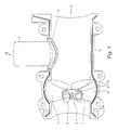
Fig. 1 is a cross-section of the intake duct showing the control flaps in the rest position, -
Fig. 2 is a cross-section of the intake duct similar to that ofFig. 1 but showing the control flaps in the active position, -
Fig. 3 is a perspective view of the intake duct showing the shaft for controlling the control flaps. - According to
Fig. 1 and2 , an air flow indicated by the arrow A circulates inside the intake duct 1 of an internal combustion engine so as to be transferred towards the cylinders of said engine. - Some of the exhaust gases of said engine, generally corresponding to between 5 and 35 % of these gases, are recycled inside the intake duct 1 via a
recycling conduit 2 according to the arrow B. - The axis of introduction B of the recycled exhaust gases into the intake duct 1 is perpendicular to the longitudinal axis A of said conduit.
- According to
Fig. 1 and2 , two control flaps 3, 4 are mounted on the inner part of the intake duct 1 after the feed opening 5 of the exhaust gases recycled via therecycling conduit 2. - These two control flaps 3, 4 which are in the form of toroidal portions are mounted jointly in rotation about
parallel hinge pins 6, 7 respectively. - According to
Fig. 1 ,2 and3 , one of these axes of articulation 6 which corresponds to an engine shaft projects from the outer part of the intake duct 1, as shown inFig. 3 . Said engine shaft is driven directly or indirectly by an actuator not shown in the figures. - The
second hinge pin 7 is driven by the engine shaft 6 by means of twotoothed portions - The control flaps 3, 4 may also be displaced between a rest position shown in
Fig. 1 in which they are retracted along the inner wall of the intake duct 1 and an active position shown inFig. 2 in which they are pulled towards one another. - This displacement of the control flaps 3, 4 between these two positions is controlled by the actuator (not shown in the figures) as a function of the pressure of the exhaust gases recycled according to the arrow B in the intake duct 1 via the
recycling conduit 2. - According to
Fig. 1 , when the pressure of the recycled exhaust gases is lower than a predetermined threshold, the actuator controls the control flaps 3, 4 so as to be positioned in the rest position in order to expose the entire cross-section of the intake duct 1, as shown inFig. 1 . - According to
Fig. 2 , when the pressure of the recycled exhaust gases increases, the actuator controls the control flaps 3, 4 so they are displaced towards the active position in order to reduce said cross-section. - In the active position, the control flaps 3, 4 cause the mixture of air and recycled exhaust gases to swirl and circulate within the inner part of the intake duct 1, and this leads to homogenisation of this mixture.
- According to
Fig. 1 and2 , the inner wall of the intake duct 1 comprisescavities 10 in which the control flaps 3, 4 are arranged in the rest position thereof, as shown inFig. 1 , in such a way that there is no loss of pressure in the gaseous flow circulating inside the intake duct 1 in the direction of arrow A. - According to
Fig. 3 and for a similar reason, thetoothed portions
Claims (6)
- Device for swirling and mixing recycled exhaust gases inside the intake duct (1) of an internal combustion engine via a recycling conduit (2), substantially perpendicularly to the longitudinal axis of said intake duct, characterised in that it is formed of two control flaps (3, 4) in the form of toroidal portions, mounted rotatably on the inner part of the intake duct (1), about hinge pins (6, 7) substantially perpendicular to the longitudinal axis of said intake duct (1) as well as to the axis of introduction of the exhaust gases recycled in said duct, said control flaps (3, 4) being displaceable in rotation between, on the one hand, a rest position in which they are retracted along the inner wall of the intake duct (1) so as to expose the entire cross-section of said duct and, on the other hand, an active position in which they are pulled towards one another so as to reduce said cross-section, and also formed of an actuator which makes it possible to control displacement of the control flaps (3, 4) between the active position and the rest position as a function of the pressure of the recycled exhaust gases introduced into the intake duct (1) via the recycling conduit (2).
- Device according to claim 1, characterised in that the inner wall of the intake duct (1) comprises cavities (10) in which the control flaps (3, 4) are arranged in the rest position thereof.
- Device according to either claim 1 or claim 2, characterised in that the control flaps (3, 4) are mounted together in rotation.
- Device according to claim 3, characterised in that the hinge pins (6, 7) of the control flaps (3, 4) are each fitted with toothed portions (8, 9) which engage with one another during displacement of said flaps between the active position and rest position thereof.
- Device according to any one of claims 1 to 4, characterised in that the control flaps (3, 4) are arranged after the recycling conduit (2) in the direction of circulation of the air flow drawn into the intake duct (1).
- Device according to any one of claims 1 to 4, characterised in that the control flaps (3, 4) are arranged before the recycling conduit (2) in the direction of circulation of the air flow drawn into the intake duct (1).
Applications Claiming Priority (1)
| Application Number | Priority Date | Filing Date | Title |
|---|---|---|---|
| FR0757816A FR2921433B1 (en) | 2007-09-25 | 2007-09-25 | DEVICE FOR ROTATING AND MIXING EXHAUST GAS RECYCLED IN THE SUCTION TUBE OF AN INTERNAL COMBUSTION ENGINE. |
Publications (2)
| Publication Number | Publication Date |
|---|---|
| EP2050949A1 true EP2050949A1 (en) | 2009-04-22 |
| EP2050949B1 EP2050949B1 (en) | 2010-07-14 |
Family
ID=39339730
Family Applications (1)
| Application Number | Title | Priority Date | Filing Date |
|---|---|---|---|
| EP08164887A Active EP2050949B1 (en) | 2007-09-25 | 2008-09-23 | Device for swirling and mixing exhaust gases |
Country Status (5)
| Country | Link |
|---|---|
| US (1) | US20090235905A1 (en) |
| EP (1) | EP2050949B1 (en) |
| AT (1) | ATE474135T1 (en) |
| DE (1) | DE602008001762D1 (en) |
| FR (1) | FR2921433B1 (en) |
Cited By (2)
| Publication number | Priority date | Publication date | Assignee | Title |
|---|---|---|---|---|
| WO2015069330A1 (en) * | 2013-11-11 | 2015-05-14 | Borgwarner Inc. | Condensing egr-mixer system |
| US9695785B2 (en) | 2013-11-11 | 2017-07-04 | Borgwarner Inc. | Turbocharger with integrated venturi mixer and EGR valve system |
Families Citing this family (1)
| Publication number | Priority date | Publication date | Assignee | Title |
|---|---|---|---|---|
| DE102015200196A1 (en) | 2015-01-09 | 2016-07-14 | Elringklinger Ag | Mixing device, internal combustion engine and method for producing a mixing device |
Citations (8)
| Publication number | Priority date | Publication date | Assignee | Title |
|---|---|---|---|---|
| FR2040559A5 (en) * | 1969-04-03 | 1971-01-22 | Simca Automobiles Sa | |
| US4066721A (en) * | 1976-08-30 | 1978-01-03 | Chrysler Corporation | Throttle body having a novel throttle blade |
| US4461150A (en) * | 1981-02-21 | 1984-07-24 | Daimler-Benz Aktiengesellschaft | Exhaust gas return pipe connection for an internal combustion engine |
| JPS6140435A (en) * | 1984-07-31 | 1986-02-26 | Keiun Kodo | Throttle valve for internal combustion engine |
| DE19607811A1 (en) * | 1996-03-01 | 1997-09-04 | Bosch Gmbh Robert | Exhaust gas recirculation valve |
| US20060060172A1 (en) * | 2004-09-21 | 2006-03-23 | Zhengbai Liu | Venturi mixing system for exhaust gas recirculation (egr) |
| EP1783341A1 (en) * | 2005-11-02 | 2007-05-09 | Arno Hofmann | Swirl-tumble generator |
| EP1826391A2 (en) * | 2006-02-24 | 2007-08-29 | Mahle International GmbH | Exhaust gas recirculation device |
Family Cites Families (7)
| Publication number | Priority date | Publication date | Assignee | Title |
|---|---|---|---|---|
| GB777803A (en) * | 1953-01-15 | 1957-06-26 | Pye Ltd | Improvements in or relating to television receivers |
| SE324644B (en) * | 1966-01-13 | 1970-06-08 | Svenska Flaektfabriken Ab | |
| DE2135840A1 (en) * | 1971-07-17 | 1973-02-08 | Baum Verfahrenstechnik | ADJUSTABLE VENTURAL HEAD FOR CLEANING FURNACE GAS |
| AU522547B2 (en) * | 1980-01-23 | 1982-06-10 | Nippondenso Co. Ltd. | Ignition coil in distributor assembly |
| JPH11166699A (en) * | 1997-12-02 | 1999-06-22 | Nippon Air Liquide Kk | Flow control device for exhaust duct in cylinder cabinet |
| US6227182B1 (en) * | 1998-06-09 | 2001-05-08 | Nissan Motor Co., Ltd. | Exhaust gas recirculation control system for internal combustion engine |
| DE10140314A1 (en) * | 2001-08-16 | 2003-02-27 | Daimler Chrysler Ag | Intake system for an internal combustion engine |
-
2007
- 2007-09-25 FR FR0757816A patent/FR2921433B1/en not_active Expired - Fee Related
-
2008
- 2008-09-23 DE DE602008001762T patent/DE602008001762D1/en active Active
- 2008-09-23 AT AT08164887T patent/ATE474135T1/en not_active IP Right Cessation
- 2008-09-23 EP EP08164887A patent/EP2050949B1/en active Active
- 2008-09-25 US US12/237,438 patent/US20090235905A1/en not_active Abandoned
Patent Citations (8)
| Publication number | Priority date | Publication date | Assignee | Title |
|---|---|---|---|---|
| FR2040559A5 (en) * | 1969-04-03 | 1971-01-22 | Simca Automobiles Sa | |
| US4066721A (en) * | 1976-08-30 | 1978-01-03 | Chrysler Corporation | Throttle body having a novel throttle blade |
| US4461150A (en) * | 1981-02-21 | 1984-07-24 | Daimler-Benz Aktiengesellschaft | Exhaust gas return pipe connection for an internal combustion engine |
| JPS6140435A (en) * | 1984-07-31 | 1986-02-26 | Keiun Kodo | Throttle valve for internal combustion engine |
| DE19607811A1 (en) * | 1996-03-01 | 1997-09-04 | Bosch Gmbh Robert | Exhaust gas recirculation valve |
| US20060060172A1 (en) * | 2004-09-21 | 2006-03-23 | Zhengbai Liu | Venturi mixing system for exhaust gas recirculation (egr) |
| EP1783341A1 (en) * | 2005-11-02 | 2007-05-09 | Arno Hofmann | Swirl-tumble generator |
| EP1826391A2 (en) * | 2006-02-24 | 2007-08-29 | Mahle International GmbH | Exhaust gas recirculation device |
Cited By (3)
| Publication number | Priority date | Publication date | Assignee | Title |
|---|---|---|---|---|
| WO2015069330A1 (en) * | 2013-11-11 | 2015-05-14 | Borgwarner Inc. | Condensing egr-mixer system |
| US9695785B2 (en) | 2013-11-11 | 2017-07-04 | Borgwarner Inc. | Turbocharger with integrated venturi mixer and EGR valve system |
| US9816466B2 (en) | 2013-11-11 | 2017-11-14 | Borgwarner Inc. | Condensing EGR-mixer system |
Also Published As
| Publication number | Publication date |
|---|---|
| US20090235905A1 (en) | 2009-09-24 |
| DE602008001762D1 (en) | 2010-08-26 |
| EP2050949B1 (en) | 2010-07-14 |
| FR2921433A1 (en) | 2009-03-27 |
| FR2921433B1 (en) | 2009-11-06 |
| ATE474135T1 (en) | 2010-07-15 |
Similar Documents
| Publication | Publication Date | Title |
|---|---|---|
| US10871102B2 (en) | Turbine for an exhaust turbocharger having a two-channel turbine housing and a valve for channel connection | |
| EP0939210B1 (en) | Internal combustion engine having combustion heater | |
| US9732668B2 (en) | Discharge valve and associated device | |
| JP2008530423A (en) | Exhaust throttle EGR valve module for diesel engine | |
| CN105370450A (en) | Dedicated-egr cylinder with variable charge motion | |
| CN109488639A (en) | The system and method for variable inlet equipment for compressor | |
| CN106121834A (en) | For the method and system using the vacuum of the air throttle including hollow passageway to produce | |
| EP2841744B1 (en) | Butterfly bypass valve, and throttle loss recovery system incorporating same | |
| EP2050949B1 (en) | Device for swirling and mixing exhaust gases | |
| CN115244292B (en) | Engine exhaust gas recirculation mixer, engine exhaust gas recirculation mixing method and engine system | |
| US20140102427A1 (en) | Control apparatus for internal combustion engine | |
| US9835116B2 (en) | Internal combustion engine for a motor vehicle, and method for operating such an internal combustion engine | |
| EP0967439B1 (en) | Internal combustion engine having combustion heater | |
| ITTO970100A1 (en) | DIESEL CYCLE COMBUSTION ENGINE, WITH EXHAUST GAS RECIRCULATION, EQUIPPED WITH A RECIRCULATING GAS MIXING DEVICE. | |
| EP2153048B1 (en) | Exhaust gas recirculation system for internal combustion engine | |
| EP2381079A1 (en) | Control device for internal combustion engine having supercharger | |
| US9784220B2 (en) | Intake air control apparatus of engine | |
| US20170276075A1 (en) | System and method to selectively control dual fuel engine intake air temperature | |
| US7484502B1 (en) | EGR coolant control system | |
| EP1342900A3 (en) | Stop controller for an internal combustion engine | |
| CN108691700A (en) | Internal combustion engine and method for operating the internal combustion engine | |
| WO2019087453A1 (en) | Engine system | |
| CN110578628A (en) | Arrangement for recirculation of exhaust gas | |
| KR101171930B1 (en) | Air Volume Control System of an Internal Combustion Engine on Ship | |
| CN107829820B (en) | Vacuum device for a vacuum consumer |
Legal Events
| Date | Code | Title | Description |
|---|---|---|---|
| PUAI | Public reference made under article 153(3) epc to a published international application that has entered the european phase |
Free format text: ORIGINAL CODE: 0009012 |
|
| AK | Designated contracting states |
Kind code of ref document: A1 Designated state(s): AT BE BG CH CY CZ DE DK EE ES FI FR GB GR HR HU IE IS IT LI LT LU LV MC MT NL NO PL PT RO SE SI SK TR |
|
| AX | Request for extension of the european patent |
Extension state: AL BA MK RS |
|
| 17P | Request for examination filed |
Effective date: 20090604 |
|
| 17Q | First examination report despatched |
Effective date: 20090703 |
|
| AKX | Designation fees paid |
Designated state(s): AT BE BG CH CY CZ DE DK EE ES FI FR GB GR HR HU IE IS IT LI LT LU LV MC MT NL NO PL PT RO SE SI SK TR |
|
| GRAP | Despatch of communication of intention to grant a patent |
Free format text: ORIGINAL CODE: EPIDOSNIGR1 |
|
| GRAS | Grant fee paid |
Free format text: ORIGINAL CODE: EPIDOSNIGR3 |
|
| RIN1 | Information on inventor provided before grant (corrected) |
Inventor name: PASCAL NOISEAU Inventor name: MARIMBORDES, THIERRY, DR. |
|
| GRAA | (expected) grant |
Free format text: ORIGINAL CODE: 0009210 |
|
| AK | Designated contracting states |
Kind code of ref document: B1 Designated state(s): AT BE BG CH CY CZ DE DK EE ES FI FR GB GR HR HU IE IS IT LI LT LU LV MC MT NL NO PL PT RO SE SI SK TR |
|
| REG | Reference to a national code |
Ref country code: GB Ref legal event code: FG4D |
|
| REG | Reference to a national code |
Ref country code: CH Ref legal event code: EP |
|
| REG | Reference to a national code |
Ref country code: IE Ref legal event code: FG4D |
|
| REF | Corresponds to: |
Ref document number: 602008001762 Country of ref document: DE Date of ref document: 20100826 Kind code of ref document: P |
|
| REG | Reference to a national code |
Ref country code: NL Ref legal event code: VDEP Effective date: 20100714 |
|
| LTIE | Lt: invalidation of european patent or patent extension |
Effective date: 20100714 |
|
| PG25 | Lapsed in a contracting state [announced via postgrant information from national office to epo] |
Ref country code: FI Free format text: LAPSE BECAUSE OF FAILURE TO SUBMIT A TRANSLATION OF THE DESCRIPTION OR TO PAY THE FEE WITHIN THE PRESCRIBED TIME-LIMIT Effective date: 20100714 Ref country code: AT Free format text: LAPSE BECAUSE OF FAILURE TO SUBMIT A TRANSLATION OF THE DESCRIPTION OR TO PAY THE FEE WITHIN THE PRESCRIBED TIME-LIMIT Effective date: 20100714 Ref country code: NO Free format text: LAPSE BECAUSE OF FAILURE TO SUBMIT A TRANSLATION OF THE DESCRIPTION OR TO PAY THE FEE WITHIN THE PRESCRIBED TIME-LIMIT Effective date: 20101014 Ref country code: NL Free format text: LAPSE BECAUSE OF FAILURE TO SUBMIT A TRANSLATION OF THE DESCRIPTION OR TO PAY THE FEE WITHIN THE PRESCRIBED TIME-LIMIT Effective date: 20100714 Ref country code: LT Free format text: LAPSE BECAUSE OF FAILURE TO SUBMIT A TRANSLATION OF THE DESCRIPTION OR TO PAY THE FEE WITHIN THE PRESCRIBED TIME-LIMIT Effective date: 20100714 |
|
| PG25 | Lapsed in a contracting state [announced via postgrant information from national office to epo] |
Ref country code: SI Free format text: LAPSE BECAUSE OF FAILURE TO SUBMIT A TRANSLATION OF THE DESCRIPTION OR TO PAY THE FEE WITHIN THE PRESCRIBED TIME-LIMIT Effective date: 20100714 Ref country code: PL Free format text: LAPSE BECAUSE OF FAILURE TO SUBMIT A TRANSLATION OF THE DESCRIPTION OR TO PAY THE FEE WITHIN THE PRESCRIBED TIME-LIMIT Effective date: 20100714 Ref country code: IS Free format text: LAPSE BECAUSE OF FAILURE TO SUBMIT A TRANSLATION OF THE DESCRIPTION OR TO PAY THE FEE WITHIN THE PRESCRIBED TIME-LIMIT Effective date: 20101114 Ref country code: HR Free format text: LAPSE BECAUSE OF FAILURE TO SUBMIT A TRANSLATION OF THE DESCRIPTION OR TO PAY THE FEE WITHIN THE PRESCRIBED TIME-LIMIT Effective date: 20100714 Ref country code: CY Free format text: LAPSE BECAUSE OF FAILURE TO SUBMIT A TRANSLATION OF THE DESCRIPTION OR TO PAY THE FEE WITHIN THE PRESCRIBED TIME-LIMIT Effective date: 20100714 Ref country code: BG Free format text: LAPSE BECAUSE OF FAILURE TO SUBMIT A TRANSLATION OF THE DESCRIPTION OR TO PAY THE FEE WITHIN THE PRESCRIBED TIME-LIMIT Effective date: 20101014 |
|
| PG25 | Lapsed in a contracting state [announced via postgrant information from national office to epo] |
Ref country code: GR Free format text: LAPSE BECAUSE OF FAILURE TO SUBMIT A TRANSLATION OF THE DESCRIPTION OR TO PAY THE FEE WITHIN THE PRESCRIBED TIME-LIMIT Effective date: 20101015 Ref country code: SE Free format text: LAPSE BECAUSE OF FAILURE TO SUBMIT A TRANSLATION OF THE DESCRIPTION OR TO PAY THE FEE WITHIN THE PRESCRIBED TIME-LIMIT Effective date: 20100714 Ref country code: LV Free format text: LAPSE BECAUSE OF FAILURE TO SUBMIT A TRANSLATION OF THE DESCRIPTION OR TO PAY THE FEE WITHIN THE PRESCRIBED TIME-LIMIT Effective date: 20100714 Ref country code: BE Free format text: LAPSE BECAUSE OF FAILURE TO SUBMIT A TRANSLATION OF THE DESCRIPTION OR TO PAY THE FEE WITHIN THE PRESCRIBED TIME-LIMIT Effective date: 20100714 |
|
| PG25 | Lapsed in a contracting state [announced via postgrant information from national office to epo] |
Ref country code: MC Free format text: LAPSE BECAUSE OF NON-PAYMENT OF DUE FEES Effective date: 20100930 Ref country code: DK Free format text: LAPSE BECAUSE OF FAILURE TO SUBMIT A TRANSLATION OF THE DESCRIPTION OR TO PAY THE FEE WITHIN THE PRESCRIBED TIME-LIMIT Effective date: 20100714 |
|
| PLBE | No opposition filed within time limit |
Free format text: ORIGINAL CODE: 0009261 |
|
| STAA | Information on the status of an ep patent application or granted ep patent |
Free format text: STATUS: NO OPPOSITION FILED WITHIN TIME LIMIT |
|
| PG25 | Lapsed in a contracting state [announced via postgrant information from national office to epo] |
Ref country code: IT Free format text: LAPSE BECAUSE OF FAILURE TO SUBMIT A TRANSLATION OF THE DESCRIPTION OR TO PAY THE FEE WITHIN THE PRESCRIBED TIME-LIMIT Effective date: 20100714 Ref country code: RO Free format text: LAPSE BECAUSE OF FAILURE TO SUBMIT A TRANSLATION OF THE DESCRIPTION OR TO PAY THE FEE WITHIN THE PRESCRIBED TIME-LIMIT Effective date: 20100714 Ref country code: CZ Free format text: LAPSE BECAUSE OF FAILURE TO SUBMIT A TRANSLATION OF THE DESCRIPTION OR TO PAY THE FEE WITHIN THE PRESCRIBED TIME-LIMIT Effective date: 20100714 Ref country code: SK Free format text: LAPSE BECAUSE OF FAILURE TO SUBMIT A TRANSLATION OF THE DESCRIPTION OR TO PAY THE FEE WITHIN THE PRESCRIBED TIME-LIMIT Effective date: 20100714 Ref country code: EE Free format text: LAPSE BECAUSE OF FAILURE TO SUBMIT A TRANSLATION OF THE DESCRIPTION OR TO PAY THE FEE WITHIN THE PRESCRIBED TIME-LIMIT Effective date: 20100714 |
|
| 26N | No opposition filed |
Effective date: 20110415 |
|
| PG25 | Lapsed in a contracting state [announced via postgrant information from national office to epo] |
Ref country code: ES Free format text: LAPSE BECAUSE OF FAILURE TO SUBMIT A TRANSLATION OF THE DESCRIPTION OR TO PAY THE FEE WITHIN THE PRESCRIBED TIME-LIMIT Effective date: 20101025 |
|
| REG | Reference to a national code |
Ref country code: DE Ref legal event code: R097 Ref document number: 602008001762 Country of ref document: DE Effective date: 20110415 |
|
| PG25 | Lapsed in a contracting state [announced via postgrant information from national office to epo] |
Ref country code: IE Free format text: LAPSE BECAUSE OF NON-PAYMENT OF DUE FEES Effective date: 20100923 |
|
| PG25 | Lapsed in a contracting state [announced via postgrant information from national office to epo] |
Ref country code: MT Free format text: LAPSE BECAUSE OF FAILURE TO SUBMIT A TRANSLATION OF THE DESCRIPTION OR TO PAY THE FEE WITHIN THE PRESCRIBED TIME-LIMIT Effective date: 20100714 |
|
| PG25 | Lapsed in a contracting state [announced via postgrant information from national office to epo] |
Ref country code: HU Free format text: LAPSE BECAUSE OF FAILURE TO SUBMIT A TRANSLATION OF THE DESCRIPTION OR TO PAY THE FEE WITHIN THE PRESCRIBED TIME-LIMIT Effective date: 20110115 Ref country code: LU Free format text: LAPSE BECAUSE OF NON-PAYMENT OF DUE FEES Effective date: 20100923 |
|
| PG25 | Lapsed in a contracting state [announced via postgrant information from national office to epo] |
Ref country code: TR Free format text: LAPSE BECAUSE OF FAILURE TO SUBMIT A TRANSLATION OF THE DESCRIPTION OR TO PAY THE FEE WITHIN THE PRESCRIBED TIME-LIMIT Effective date: 20100714 |
|
| REG | Reference to a national code |
Ref country code: CH Ref legal event code: PL |
|
| GBPC | Gb: european patent ceased through non-payment of renewal fee |
Effective date: 20120923 |
|
| PG25 | Lapsed in a contracting state [announced via postgrant information from national office to epo] |
Ref country code: CH Free format text: LAPSE BECAUSE OF NON-PAYMENT OF DUE FEES Effective date: 20120930 Ref country code: PT Free format text: LAPSE BECAUSE OF NON-PAYMENT OF DUE FEES Effective date: 20100714 Ref country code: LI Free format text: LAPSE BECAUSE OF NON-PAYMENT OF DUE FEES Effective date: 20120930 Ref country code: GB Free format text: LAPSE BECAUSE OF NON-PAYMENT OF DUE FEES Effective date: 20120923 |
|
| REG | Reference to a national code |
Ref country code: FR Ref legal event code: PLFP Year of fee payment: 9 |
|
| REG | Reference to a national code |
Ref country code: FR Ref legal event code: PLFP Year of fee payment: 10 |
|
| REG | Reference to a national code |
Ref country code: DE Ref legal event code: R081 Ref document number: 602008001762 Country of ref document: DE Owner name: MANN+HUMMEL GMBH, DE Free format text: FORMER OWNER: MANN + HUMMEL GMBH, 71638 LUDWIGSBURG, DE |
|
| REG | Reference to a national code |
Ref country code: FR Ref legal event code: PLFP Year of fee payment: 11 |
|
| REG | Reference to a national code |
Ref country code: DE Ref legal event code: R081 Ref document number: 602008001762 Country of ref document: DE Owner name: MOLDTECS-01-2022 GMBH, DE Free format text: FORMER OWNER: MANN+HUMMEL GMBH, 71636 LUDWIGSBURG, DE |
|
| P01 | Opt-out of the competence of the unified patent court (upc) registered |
Effective date: 20240220 |
|
| PGFP | Annual fee paid to national office [announced via postgrant information from national office to epo] |
Ref country code: DE Payment date: 20250919 Year of fee payment: 18 |
|
| PGFP | Annual fee paid to national office [announced via postgrant information from national office to epo] |
Ref country code: FR Payment date: 20250919 Year of fee payment: 18 |