EP2050684A2 - Slider end stop for reclosable plastic bag, and reclosable plastic bag having the same - Google Patents
Slider end stop for reclosable plastic bag, and reclosable plastic bag having the same Download PDFInfo
- Publication number
- EP2050684A2 EP2050684A2 EP08105561A EP08105561A EP2050684A2 EP 2050684 A2 EP2050684 A2 EP 2050684A2 EP 08105561 A EP08105561 A EP 08105561A EP 08105561 A EP08105561 A EP 08105561A EP 2050684 A2 EP2050684 A2 EP 2050684A2
- Authority
- EP
- European Patent Office
- Prior art keywords
- plastic bag
- zipper
- film
- reclosable plastic
- slider
- Prior art date
- Legal status (The legal status is an assumption and is not a legal conclusion. Google has not performed a legal analysis and makes no representation as to the accuracy of the status listed.)
- Withdrawn
Links
- 239000004033 plastic Substances 0.000 title claims abstract description 66
- 229920003023 plastic Polymers 0.000 title claims abstract description 66
- 238000003780 insertion Methods 0.000 claims abstract description 17
- 230000037431 insertion Effects 0.000 claims abstract description 17
- 230000004927 fusion Effects 0.000 claims description 6
- 238000012856 packing Methods 0.000 claims description 6
- 238000004519 manufacturing process Methods 0.000 description 4
- 238000003825 pressing Methods 0.000 description 3
- 239000000463 material Substances 0.000 description 2
- 238000012986 modification Methods 0.000 description 2
- 230000004048 modification Effects 0.000 description 2
- -1 polypropylene Polymers 0.000 description 2
- 229930182556 Polyacetal Natural products 0.000 description 1
- 239000004698 Polyethylene Substances 0.000 description 1
- 239000004743 Polypropylene Substances 0.000 description 1
- 239000004793 Polystyrene Substances 0.000 description 1
- 238000007792 addition Methods 0.000 description 1
- 238000005516 engineering process Methods 0.000 description 1
- 238000010438 heat treatment Methods 0.000 description 1
- 238000000034 method Methods 0.000 description 1
- 229920000515 polycarbonate Polymers 0.000 description 1
- 239000004417 polycarbonate Substances 0.000 description 1
- 229920000728 polyester Polymers 0.000 description 1
- 229920000573 polyethylene Polymers 0.000 description 1
- 229920006324 polyoxymethylene Polymers 0.000 description 1
- 229920001155 polypropylene Polymers 0.000 description 1
- 229920002223 polystyrene Polymers 0.000 description 1
- 238000007789 sealing Methods 0.000 description 1
- 238000003860 storage Methods 0.000 description 1
- 238000006467 substitution reaction Methods 0.000 description 1
- 238000009461 vacuum packaging Methods 0.000 description 1
Images





Classifications
-
- B—PERFORMING OPERATIONS; TRANSPORTING
- B65—CONVEYING; PACKING; STORING; HANDLING THIN OR FILAMENTARY MATERIAL
- B65D—CONTAINERS FOR STORAGE OR TRANSPORT OF ARTICLES OR MATERIALS, e.g. BAGS, BARRELS, BOTTLES, BOXES, CANS, CARTONS, CRATES, DRUMS, JARS, TANKS, HOPPERS, FORWARDING CONTAINERS; ACCESSORIES, CLOSURES, OR FITTINGS THEREFOR; PACKAGING ELEMENTS; PACKAGES
- B65D33/00—Details of, or accessories for, sacks or bags
- B65D33/16—End- or aperture-closing arrangements or devices
- B65D33/25—Riveting; Dovetailing; Screwing; using press buttons or slide fasteners
-
- B—PERFORMING OPERATIONS; TRANSPORTING
- B65—CONVEYING; PACKING; STORING; HANDLING THIN OR FILAMENTARY MATERIAL
- B65D—CONTAINERS FOR STORAGE OR TRANSPORT OF ARTICLES OR MATERIALS, e.g. BAGS, BARRELS, BOTTLES, BOXES, CANS, CARTONS, CRATES, DRUMS, JARS, TANKS, HOPPERS, FORWARDING CONTAINERS; ACCESSORIES, CLOSURES, OR FITTINGS THEREFOR; PACKAGING ELEMENTS; PACKAGES
- B65D33/00—Details of, or accessories for, sacks or bags
- B65D33/16—End- or aperture-closing arrangements or devices
- B65D33/25—Riveting; Dovetailing; Screwing; using press buttons or slide fasteners
- B65D33/2508—Riveting; Dovetailing; Screwing; using press buttons or slide fasteners using slide fasteners with interlocking members having a substantially uniform section throughout the length of the fastener; Sliders therefor
- B65D33/2589—Bag or slide fastener details cooperating with the slider, e.g. details for removing or installing the slider
- B65D33/259—End stops
-
- B—PERFORMING OPERATIONS; TRANSPORTING
- B65—CONVEYING; PACKING; STORING; HANDLING THIN OR FILAMENTARY MATERIAL
- B65D—CONTAINERS FOR STORAGE OR TRANSPORT OF ARTICLES OR MATERIALS, e.g. BAGS, BARRELS, BOTTLES, BOXES, CANS, CARTONS, CRATES, DRUMS, JARS, TANKS, HOPPERS, FORWARDING CONTAINERS; ACCESSORIES, CLOSURES, OR FITTINGS THEREFOR; PACKAGING ELEMENTS; PACKAGES
- B65D33/00—Details of, or accessories for, sacks or bags
- B65D33/16—End- or aperture-closing arrangements or devices
-
- Y—GENERAL TAGGING OF NEW TECHNOLOGICAL DEVELOPMENTS; GENERAL TAGGING OF CROSS-SECTIONAL TECHNOLOGIES SPANNING OVER SEVERAL SECTIONS OF THE IPC; TECHNICAL SUBJECTS COVERED BY FORMER USPC CROSS-REFERENCE ART COLLECTIONS [XRACs] AND DIGESTS
- Y10—TECHNICAL SUBJECTS COVERED BY FORMER USPC
- Y10T—TECHNICAL SUBJECTS COVERED BY FORMER US CLASSIFICATION
- Y10T24/00—Buckles, buttons, clasps, etc.
- Y10T24/25—Zipper or required component thereof
- Y10T24/2561—Slider having specific configuration, construction, adaptation, or material
- Y10T24/2582—Slider having specific configuration, construction, adaptation, or material having specific contour or arrangement of converging channel, separator island, or wing
-
- Y—GENERAL TAGGING OF NEW TECHNOLOGICAL DEVELOPMENTS; GENERAL TAGGING OF CROSS-SECTIONAL TECHNOLOGIES SPANNING OVER SEVERAL SECTIONS OF THE IPC; TECHNICAL SUBJECTS COVERED BY FORMER USPC CROSS-REFERENCE ART COLLECTIONS [XRACs] AND DIGESTS
- Y10—TECHNICAL SUBJECTS COVERED BY FORMER USPC
- Y10T—TECHNICAL SUBJECTS COVERED BY FORMER US CLASSIFICATION
- Y10T24/00—Buckles, buttons, clasps, etc.
- Y10T24/25—Zipper or required component thereof
- Y10T24/2598—Zipper or required component thereof including means for obstructing movement of slider
Definitions
- the present invention relates to a slider end stop for a reclosable plastic bag and a reclosable plastic bag having the same. More particularly, the present invention relates to a slider end stop for a reclosable plastic bag, which has a through-hole at the center and attached, such as rivet connection.
- Plastic bags have been widely used in houses and commerce. In particular, plastic bags are frequently used for food storage or packing. Some of the plastic bags have zippers or fasteners at the upper portions to be repeatedly opened and closed. The zippers and fasteners close the upper portion of the plastic bags by engaging two sides. Currently, various types of zippers or fasteners have been proposed.
- U.S Patent No. 5067208 discloses a configuration that prevents a slider from separating by having an end clamp formed of a strap member covering a zipper.
- a rivet-shaped member is provided to a side of the strap of the end clamp and an opening is formed at the other end, such that a rivet-shaped member is connected to the opening with the strap folded, in which the end clamp is attached to the plastic bag.
- this configuration has a problem in that the configuration of the end clamp is complicated. Further, the end clamp is exposed to the outside at the upper portion of the plastic bag, thereby negating the aesthetic appearance. Meanwhile, there is a problem in that the configuration of the slider disclosed in the above Patent is complicated.
- an end stop formed by deforming a part of the upper portion of a plastic bag using ultrasonic wave or heat and a method of manufacturing the same are disclosed in Korean Patent Publication No. 10-2004-0031660 (published on April 13, 2004 , same as U.S Patent Publication No. 2004/0066985 ).
- a large number of technologies that form an end stop using heat have been disclosed, other than the above Patent Publication.
- the configuration of the end stop since the upper portion of a plastic bag is deformed, the aesthetic appearance is detracted. Further, because a heating process is required, manufacturing is inconvenient.
- end stoppers in the related art are limited in that their only function is to prevent the sliders from separating and they do not have other functions. Meanwhile, there is a problem in that the configurations of the sliders in the related art are complicated and manufacturing the sliders is difficult.
- an object of the present invention to provide an end stop having flange-shaped end stop that prevents a slider, which engages a zipper, from separating from ends of the zipper by being inserted in an insertion hole formed through a first film and a second film of a plastic bag, and a through-hole at the center, and a reclosable plastic bag having the end stop.
- the reclosable plastic bag includes: a first film and a second film of which both sides and lower sides adhere to each other and the combined upper side is open; a zipper including a first zipper and a second zipper that are provided on the insides of the upper sides of the first film and second film and engaged with each other; a slider engaging the first zipper with the second zipper, sliding on the zipper; and end stops of which both ends are formed in flange shapes and that each have a through-hole at the center to prevent the slider from separating from the ends of the zipper by being fitted in insertion holes formed through the first film and the second film.
- the end stop has a body having the through hole and a flange protruding outside from an end of the body, and is fitted in the insertion hole by inserting the body into the insertion hole and then deforming the other end of the body, such as rivet connection.
- the insertion hole may be formed at end stop fitting portions of the first film and second film adhering to each other.
- the slider has a first side wall and a second side wall of which ends are connected to be open at a side, and a first curved portion and a second curved portion corresponding to the protruding zipper are respectively formed on the insides of the first side wall and the second side wall.
- a first locking protrusion and a second locking protrusion are formed under the first curved portion and the second curved portion of the first side wall and the second side wall of the slider to prevent the slider to separating upward from the zipper.
- At least any one of the first side wall and the second side wall of the slider has an end stop fitting hole where the end stop is fitted.
- At least any one of the first side wall and the second side wall of the slider has an operation protrusion on the outside.
- the reclosable plastic bag may further include a vacuum valve to vacuum the inside of the plastic bag.
- the vacuum valve includes: a lower body including a fusion plate attached to the inside of any one of the first film and the second film and a circular protrusion protruding up from the fusion plate and exposed outside of the film; a rubber packing disposed inside the lower body and functions as a valve; and an upper body including a rim fitted on the outside of the circular protrusion, a cover having a cap fitted on the inner circumference of the circular protrusion, and a connecting strap connecting the rim with the cover.
- a slider end stop that can be simply achieved is provided.
- the end stop has an advantage of connecting a rope because it has a through-hole at the center.
- FIG. 1 is a perspective view of a reclosable plastic bag having end stops according to a preferred embodiment of the invention.
- a plastic bag according to the invention includes a first film 12 and a second film 14 that are formed of plastic and adhered to each other with the combined upper side open, a zipper 20 including a first zipper 20a and a second zipper 20b and the open portion of the first film 12 and the second film 14, a slider 30 closing the zipper 20, and end stops 40a, 40b preventing the slider 30 from separating from the ends of the zipper 20.
- the first film 12 and the second film 14 adhere to each other at the left and right sides by side adhering portions 16a, 16b, and the lower sides adhere to each other by lower adhering portions 18, thereby forming a bag.
- the first film 12 and the second film 14 may be formed of polypropylene, polyethylene, polystyrene, polycarbonate, polyester, polyacetal, or a combination including one or two or more of them.
- the first zipper 20a and the second zipper 20b are provided on the inside of the upper sides of the first film 12 and the second film 14.
- Each of the first zipper 20a and the second zipper 20b has projections and grooves (not shown), such that the projections and the grooves are correspondingly engaged.
- the upper side of a plastic bag 10 can be closed by engaging the first zipper 20a with the second zipper 20b.
- the first zipper 20a and the second zipper 20b are attached slightly lower than the upper end of the first film 12 and the second film 14, such that a small extension 22 remains above the zipper 20.
- the slider 30 is disposed to cover the extension 22 of the plastic bag 10 and the front and rear sides of the zipper 20.
- the slider 30 may be formed in a U-shape with a side open and inserted from the above of the plastic bag 10.
- the slider 30 can move, such that first zipper 20a and the second zipper 20b are engaged by moving the slider 30 on the zipper 20 while pressing the front and rear sides of the slider with a hand.
- the end stops 40a, 40b are provided to both ends of the extension 22.
- the end stops 40a, 40b are attached to both ends of the extension 22, such as rivet.
- the side adhering portions 16a, 16b extend to the extension 22 to form end stop joints 24a, 24b.
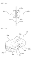
- FIG. 2 is a perspective view illustrating attaching end stop members to the reclosable plastic bag according to a preferred embodiment of the invention
- FIG. 3 is a cross-sectional view of the end stop members that are attached to the reclosable plastic bag according to a preferred embodiment of the invention
- FIG. 4 is a view illustrating forming an end stop by attaching the end stop member to the reclosable plastic bag according to a preferred embodiment of the invention.
- the members for the end stops 40a, 40b each have a hollow pipe-shaped body 44 and a flange 46 radially protruding from the upper side of the body 44.
- the members for the end stops 40a, 40b may be formed of the same material as the material of the first film 12 and the second film 14.
- insertion holes 42a where the members for the end stops 40a, 40b are formed through the upper portion of the ends of the zipper 20.
- the member for the end stop 40a is fitted in the insertion hole 42a by inserting the member for the end stop 40a into the insertion hole 42a and then pressing the lower side of the body 44 with a second anvil 48b while supporting the upper side of the flange with a first anvil 48a, thereby forming the end stop 40a.
- This process is similar to fitting a rivet into plates overlapping.
- both ends, which are exposed to the outside, of each of the end stops 40a, 40b fitted in the insertion holes 42a are formed in circular flange shapes, which can be considered to be connected with the hollow bodies 44.
- the slider 30 that is suitable to the end stops 40a, 40b of the plastic bag 10 according to a preferred embodiment of the invention is described next.
- FIG. 5 is a perspective view of the slider for a reclosable plastic bag according to a preferred embodiment of the invention and FIG. 6 is a side view of the slider for a reclosable plastic bag according to a preferred embodiment of the invention.
- the slider 30 is formed in a U-shape with a first side wall 32a and a second side wall 32b of which ends are connected. The following description is provided on the assumption that the connection of the first side wall 32a and the second side wall 32b of the slider is the upper side and the open side is the lower side.
- a first end stop locking groove 34a is formed on the inside of the first side wall 32a and a first curved portion 38a corresponding to the first zipper 20a protruding outside is formed under the first end stop locking groove 34a. Further, a first locking protrusion 36a is formed under the first curved portion 38a on the firs side wall 32a to prevent the slider 30 from separating upward from the zipper 20. Similarly, a second end stop locking groove 34b, a second curved portion 38b, and a second locking protrusion 36b are formed on the second side wall 32b. It is preferable that the pairs of the first and second end stop locking grooves 34a, 34b are formed at left and right sides on the first side wall 32a and the second side wall 32b, respectively. The first and second end stop locking grooves 34a, 34b may be preferably formed in semicircular shapes, corresponding to the end stops 40a, 40b.
- the slider 30 is attached on the upper side of the plastic bag 10 such that the zipper 20 is disposed between the first curved portion 38a and the second curved portion 38b. Therefore, the slider cannot be easily separated from the zipper 20. Further, the locking protrusions 36a, 36b provided at the lower side on the insides of the slider 30 additionally prevent the slider 30 from separating from the zipper 20.
- first and second operation protrusions 39a, 39b protrude from the outsides of the first side wall 32a and the second side wall 32b to allow a user to easily move the slider to the left and right.
- FIG. 7 is a perspective view illustrating the slider stopped by an end stop, in the reclosable plastic bag according to a preferred embodiment of the invention.
- FIG. 8 is a view showing an example of attaching a rope to the end stops of the reclosable plastic bag according to a preferred embodiment of the invention.
- the end stops 40a, 40b preferably have through-holes and are attached to the upper side of the plastic bag, such rivet connection.
- a rope 49 can be inserted in the through-holes in the end stops 40a, 40b. Accordingly, the user can easily carry or hang the plastic bag 10 by connecting the rope 49 to the plastic bag 10.
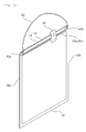
- FIG. 9 is a perspective view of a reclosable plastic bag equipped with a vacuum valve
- FIG. 10 is an exploded perspective view of the vacuum valve
- FIG. 11 is an assembly view of the vacuum valve.
- the vacuum valve 50 is equipped to any one of the first film 12 and the second film 20 of a plastic bag 10, and functions as a one-way valve.
- the vacuum valve includes a lower body 52, a rubber packing 60, and an upper body 66.
- the lower body 50 includes a fusion plate 54 and a circular protrusion 56 protruding up from the fusion plate 54 adheres to the inside of the film (12 or 14) of the plastic bag 10 and the circular protrusion 56 protrudes outside from the inside of the film (12 or 14).
- the rubber packing 60 includes a contact plate 60, a conical protrusion 64, and a connecting bar 64.
- the rubber packing 60 is combined with the lower body 50.
- the upper body 99 includes a doughnut-shaped rim 68, a cover 72, and a connecting strap 74 connecting the rim 68 with the cover 72.
- the rim 68 is fitted on the outer circumference of the circular protrusion 56. It is preferable that the rim 68 is force-fitted to the circular protrusion 56 to prevent the rim 68 from separating after being fitted.
- the cover 72 has a circular cap 70 that protrudes to ensure sealing the vacuum valve 50 by being attaching to the inner circumference of the circular protrusion 56. Further, the cover 72 has a protruding handle 73.
- the lower body 52 is attached to the inside of the film (12 or 14) and then the upper body 66 can be easily combined with the lower body 52 from the outside of the film (12 or 14).
Landscapes
- Engineering & Computer Science (AREA)
- Mechanical Engineering (AREA)
- Bag Frames (AREA)
Abstract
Description
- The present invention relates to a slider end stop for a reclosable plastic bag and a reclosable plastic bag having the same. More particularly, the present invention relates to a slider end stop for a reclosable plastic bag, which has a through-hole at the center and attached, such as rivet connection.
- Plastic bags have been widely used in houses and commerce. In particular, plastic bags are frequently used for food storage or packing. Some of the plastic bags have zippers or fasteners at the upper portions to be repeatedly opened and closed. The zippers and fasteners close the upper portion of the plastic bags by engaging two sides. Currently, various types of zippers or fasteners have been proposed.
- Even though engagement of the zipper or fastener can be performed by human hands, this becomes inconvenient to the user. In order to make it easier for a user, a plastic bag having a slider pressing the zipper or fastener in the engagement direction has been proposed. Further, end stops that restrict side movement of the slider are provided to prevent the slider from separating from the ends of the zipper or fastener.
- The configuration of an end stop in the related art is as follow.
-
U.S Patent No. 5067208 (published on November 26, 1991 ) discloses a configuration that prevents a slider from separating by having an end clamp formed of a strap member covering a zipper. A rivet-shaped member is provided to a side of the strap of the end clamp and an opening is formed at the other end, such that a rivet-shaped member is connected to the opening with the strap folded, in which the end clamp is attached to the plastic bag. However, this configuration has a problem in that the configuration of the end clamp is complicated. Further, the end clamp is exposed to the outside at the upper portion of the plastic bag, thereby negating the aesthetic appearance. Meanwhile, there is a problem in that the configuration of the slider disclosed in the above Patent is complicated. - In another prior art, an end stop formed by deforming a part of the upper portion of a plastic bag using ultrasonic wave or heat and a method of manufacturing the same are disclosed in Korean Patent Publication No.
10-2004-0031660 (published on April 13, 2004 U.S Patent Publication No. 2004/0066985 ). A large number of technologies that form an end stop using heat have been disclosed, other than the above Patent Publication. However, according to the configuration of the end stop, since the upper portion of a plastic bag is deformed, the aesthetic appearance is detracted. Further, because a heating process is required, manufacturing is inconvenient. - Further, end stoppers in the related art are limited in that their only function is to prevent the sliders from separating and they do not have other functions. Meanwhile, there is a problem in that the configurations of the sliders in the related art are complicated and manufacturing the sliders is difficult.
- Accordingly, it is an object of the present invention to provide an end stop having flange-shaped end stop that prevents a slider, which engages a zipper, from separating from ends of the zipper by being inserted in an insertion hole formed through a first film and a second film of a plastic bag, and a through-hole at the center, and a reclosable plastic bag having the end stop.
- The reclosable plastic bag includes: a first film and a second film of which both sides and lower sides adhere to each other and the combined upper side is open; a zipper including a first zipper and a second zipper that are provided on the insides of the upper sides of the first film and second film and engaged with each other; a slider engaging the first zipper with the second zipper, sliding on the zipper; and end stops of which both ends are formed in flange shapes and that each have a through-hole at the center to prevent the slider from separating from the ends of the zipper by being fitted in insertion holes formed through the first film and the second film.
- The end stop has a body having the through hole and a flange protruding outside from an end of the body, and is fitted in the insertion hole by inserting the body into the insertion hole and then deforming the other end of the body, such as rivet connection.
- Preferably, the insertion hole may be formed at end stop fitting portions of the first film and second film adhering to each other.
- Further, the slider has a first side wall and a second side wall of which ends are connected to be open at a side, and a first curved portion and a second curved portion corresponding to the protruding zipper are respectively formed on the insides of the first side wall and the second side wall.
- Preferably, a first locking protrusion and a second locking protrusion are formed under the first curved portion and the second curved portion of the first side wall and the second side wall of the slider to prevent the slider to separating upward from the zipper.
- Preferably, at least any one of the first side wall and the second side wall of the slider has an end stop fitting hole where the end stop is fitted.
- Preferably, at least any one of the first side wall and the second side wall of the slider has an operation protrusion on the outside.
- Meanwhile, the reclosable plastic bag may further include a vacuum valve to vacuum the inside of the plastic bag.
- Preferably, the vacuum valve includes: a lower body including a fusion plate attached to the inside of any one of the first film and the second film and a circular protrusion protruding up from the fusion plate and exposed outside of the film; a rubber packing disposed inside the lower body and functions as a valve; and an upper body including a rim fitted on the outside of the circular protrusion, a cover having a cap fitted on the inner circumference of the circular protrusion, and a connecting strap connecting the rim with the cover.
- According to the invention, a slider end stop that can be simply achieved is provided. The end stop has an advantage of connecting a rope because it has a through-hole at the center. Further, according to the invention, a slider that can be simply manufactured and has durability, and is detachable for reuse, if needed. Therefore, the invention improves ease of manufacturing and convenience of use.
-
-
FIG. 1 is a perspective view of a reclosable plastic bag having end stops according to a preferred embodiment of the invention; -
FIG. 2 is a perspective view illustrating attaching end stop members to the reclosable plastic bag according to a preferred embodiment of the invention; -
FIG. 3 is a cross-sectional view of the end stop members that are attached to the reclosable plastic bag according to a preferred embodiment of the invention; -
FIG. 4 is a view illustrating forming an end stop by attaching the end stop member to the reclosable plastic bag according to a preferred embodiment of the invention; -
FIG. 5 is a perspective view of the slider for a reclosable plastic bag according to a preferred embodiment of the invention; -
FIG. 6 is a side view of the slider for a reclosable plastic bag according to a preferred embodiment of the invention.; -
FIG. 7 is a perspective view illustrating the slider stopped by an end stop, in the reclosable plastic bag according to a preferred embodiment of the invention; -
FIG. 8 is a view showing an example of attaching a rope to the end stops of the reclosable plastic bag according to a preferred embodiment of the invention; -
FIG. 9 is a perspective view of a reclosable plastic bag equipped with a vacuum valve according to a preferred embodiment of the invention; -
FIG. 10 is an exploded perspective view of the vacuum valve; and -
FIG. 11 is an assembly view of the vacuum valve. - Preferred embodiments of the invention are described hereafter in detail with reference to the accompanying drawings. Giving reference numerals to components in each figure, it should be understood first that the same components are referred by the same reference numerals even if they are shown in different figures. Describing the invention herein, when it is considered that detailed description about related known configurations or functions makes the aspects of the invention unclear, the detailed description may be omitted. Further, preferred embodiments of the invention are described hereafter, but it will be apparent to those skilled in the art that various modifications and changes may be made thereto without departing from the scope and spirit of the invention.
-
FIG. 1 is a perspective view of a reclosable plastic bag having end stops according to a preferred embodiment of the invention. - A plastic bag according to the invention includes a
first film 12 and asecond film 14 that are formed of plastic and adhered to each other with the combined upper side open, azipper 20 including afirst zipper 20a and asecond zipper 20b and the open portion of thefirst film 12 and thesecond film 14, aslider 30 closing thezipper 20, and end stops 40a, 40b preventing theslider 30 from separating from the ends of thezipper 20. - The
first film 12 and thesecond film 14 adhere to each other at the left and right sides byside adhering portions portions 18, thereby forming a bag. Thefirst film 12 and thesecond film 14 may be formed of polypropylene, polyethylene, polystyrene, polycarbonate, polyester, polyacetal, or a combination including one or two or more of them. - The
first zipper 20a and thesecond zipper 20b are provided on the inside of the upper sides of thefirst film 12 and thesecond film 14. Each of thefirst zipper 20a and thesecond zipper 20b has projections and grooves (not shown), such that the projections and the grooves are correspondingly engaged. The upper side of aplastic bag 10 can be closed by engaging thefirst zipper 20a with thesecond zipper 20b. Thefirst zipper 20a and thesecond zipper 20b are attached slightly lower than the upper end of thefirst film 12 and thesecond film 14, such that asmall extension 22 remains above thezipper 20. - The
slider 30 is disposed to cover theextension 22 of theplastic bag 10 and the front and rear sides of thezipper 20. Theslider 30 may be formed in a U-shape with a side open and inserted from the above of theplastic bag 10. Theslider 30 can move, such thatfirst zipper 20a and thesecond zipper 20b are engaged by moving theslider 30 on thezipper 20 while pressing the front and rear sides of the slider with a hand. - The end stops 40a, 40b are provided to both ends of the
extension 22. The end stops 40a, 40b are attached to both ends of theextension 22, such as rivet. In order to ensure the attachment of the end stops 40a, 40b to both ends of theextension 22, it is preferable that theside adhering portions extension 22 to formend stop joints -
FIG. 2 is a perspective view illustrating attaching end stop members to the reclosable plastic bag according to a preferred embodiment of the invention,FIG. 3 is a cross-sectional view of the end stop members that are attached to the reclosable plastic bag according to a preferred embodiment of the invention, andFIG. 4 is a view illustrating forming an end stop by attaching the end stop member to the reclosable plastic bag according to a preferred embodiment of the invention. - Forming the end stops 40a, 40b to the
plastic bag 10 is described in detail with reference toFIGS. 2 to 4 . - The members for the end stops 40a, 40b each have a hollow pipe-shaped
body 44 and aflange 46 radially protruding from the upper side of thebody 44. The members for the end stops 40a, 40b may be formed of the same material as the material of thefirst film 12 and thesecond film 14. - Referring to
FIG. 2 ,insertion holes 42a where the members for the end stops 40a, 40b are formed through the upper portion of the ends of thezipper 20. - Referring to
FIG. 4 , the member for theend stop 40a is fitted in theinsertion hole 42a by inserting the member for theend stop 40a into theinsertion hole 42a and then pressing the lower side of thebody 44 with asecond anvil 48b while supporting the upper side of the flange with afirst anvil 48a, thereby forming theend stop 40a. This process is similar to fitting a rivet into plates overlapping. - As a result, both ends, which are exposed to the outside, of each of the end stops 40a, 40b fitted in the
insertion holes 42a are formed in circular flange shapes, which can be considered to be connected with thehollow bodies 44. - The
slider 30 that is suitable to the end stops 40a, 40b of theplastic bag 10 according to a preferred embodiment of the invention is described next. -
FIG. 5 is a perspective view of the slider for a reclosable plastic bag according to a preferred embodiment of the invention andFIG. 6 is a side view of the slider for a reclosable plastic bag according to a preferred embodiment of the invention. - The
slider 30 is formed in a U-shape with afirst side wall 32a and asecond side wall 32b of which ends are connected. The following description is provided on the assumption that the connection of thefirst side wall 32a and thesecond side wall 32b of the slider is the upper side and the open side is the lower side. - A first end stop locking
groove 34a is formed on the inside of thefirst side wall 32a and a firstcurved portion 38a corresponding to thefirst zipper 20a protruding outside is formed under the first end stop lockinggroove 34a. Further, afirst locking protrusion 36a is formed under the firstcurved portion 38a on thefirs side wall 32a to prevent theslider 30 from separating upward from thezipper 20. Similarly, a second end stop lockinggroove 34b, a secondcurved portion 38b, and asecond locking protrusion 36b are formed on thesecond side wall 32b. It is preferable that the pairs of the first and second end stop lockinggrooves first side wall 32a and thesecond side wall 32b, respectively. The first and second end stop lockinggrooves - The
slider 30 is attached on the upper side of theplastic bag 10 such that thezipper 20 is disposed between the firstcurved portion 38a and the secondcurved portion 38b. Therefore, the slider cannot be easily separated from thezipper 20. Further, the lockingprotrusions slider 30 additionally prevent theslider 30 from separating from thezipper 20. - On the other hand, first and
second operation protrusions first side wall 32a and thesecond side wall 32b to allow a user to easily move the slider to the left and right. -
FIG. 7 is a perspective view illustrating the slider stopped by an end stop, in the reclosable plastic bag according to a preferred embodiment of the invention. - Even though the
slider 30 moves to an end of thezipper 20 along the outsides of thezipper 20, it is stopped by theend stop 40a and cannot be separated from thezipper 20. In particular, when theslider 30 has the end stop lockinggroove 34a, theend stop 40a is locked into the end stop lockinggroove 34a of theslider 30, thereby ensuring theslider 30 stops. -
FIG. 8 is a view showing an example of attaching a rope to the end stops of the reclosable plastic bag according to a preferred embodiment of the invention. - As described above, according to the invention, the end stops 40a, 40b preferably have through-holes and are attached to the upper side of the plastic bag, such rivet connection.
- Therefore, a
rope 49 can be inserted in the through-holes in the end stops 40a, 40b. Accordingly, the user can easily carry or hang theplastic bag 10 by connecting therope 49 to theplastic bag 10. - Another preferred embodiment of the invention is provided hereafter.
- The use of vacuum packing bags has rapidly increased in recent years to effectively store food.
-
FIG. 9 is a perspective view of a reclosable plastic bag equipped with a vacuum valve,FIG. 10 is an exploded perspective view of the vacuum valve, andFIG. 11 is an assembly view of the vacuum valve. - The
vacuum valve 50 is equipped to any one of thefirst film 12 and thesecond film 20 of aplastic bag 10, and functions as a one-way valve. - Referring to
FIGS. 10 and11 , the vacuum valve includes alower body 52, a rubber packing 60, and anupper body 66. - The
lower body 50 includes afusion plate 54 and acircular protrusion 56 protruding up from thefusion plate 54 adheres to the inside of the film (12 or 14) of theplastic bag 10 and thecircular protrusion 56 protrudes outside from the inside of the film (12 or 14). - The rubber packing 60 includes a
contact plate 60, aconical protrusion 64, and a connectingbar 64. The rubber packing 60 is combined with thelower body 50. - The upper body 99 includes a doughnut-shaped
rim 68, acover 72, and a connectingstrap 74 connecting therim 68 with thecover 72. Therim 68 is fitted on the outer circumference of thecircular protrusion 56. It is preferable that therim 68 is force-fitted to thecircular protrusion 56 to prevent therim 68 from separating after being fitted. Thecover 72 has acircular cap 70 that protrudes to ensure sealing thevacuum valve 50 by being attaching to the inner circumference of thecircular protrusion 56. Further, thecover 72 has a protrudinghandle 73. - According to this configuration, the
lower body 52 is attached to the inside of the film (12 or 14) and then theupper body 66 can be easily combined with thelower body 52 from the outside of the film (12 or 14). - Although the preferred embodiments of the invention have been disclosed for illustrative purposes of spirit of the invention, those skilled in the art will appreciate that various modifications, additions and substitutions are possible, without departing from the scope and sprit of the invention. Therefore, it should be understood that the above embodiments and the accompanying drawings are not limitative, but illustrative for spirit of the invention, and the spirit of the invention is not limited to the embodiments and accompanying drawings. The scope of the invention should be construed by the appended claims and all spirits within equivalences of the claims are intended to be embraced by the claims.
Claims (12)
- A reclosable plastic bag comprising:a first film and a second film of which both sides and lower sides adhere to each other and the combined upper side is open;a zipper including a first zipper and a second zipper that are provided on the insides of the upper sides of the first film and second film and engaged with each other;a slider engaging the first zipper with the second zipper, sliding on the zipper; andend stops of which both ends are formed in flange shapes and that each have a through-hole at the center to prevent the slider from separating from the ends of the zipper by being fitted in insertion holes formed through the first film and the second film.
- The reclosable plastic bag of claim 1, wherein the end stop has a body having the through hole and a flange protruding outside from an end of the body, and is fitted in the insertion hole by inserting the body into the insertion hole and then deforming the other end of the body, such as rivet connection.
- The reclosable plastic bag of claim 1 or 2, wherein the insertion hole is formed at end stop fitting portions of the first film and second film adhering to each other.
- The reclosable plastic bag of claim 3, wherein the end stop fitting portion is positioned at the upper side of the zipper.
- The reclosable plastic bag of claim 1 or 2, wherein the slider has a first side wall and a second side wall of which ends are connected to be open at a side, and a first curved portion and a second curved portion corresponding to the protruding zipper are respectively formed on the insides of the first side wall and the second side wall.
- The reclosable plastic bag of claim 5, wherein a first locking protrusion and a second locking protrusion are formed under the first curved portion and the second curved portion of the first side wall and the second side wall to prevent the slider to separating upward from the zipper.
- The reclosable plastic bag of claim 5, wherein at least any one of the first side wall and the second side wall has an end stop fitting hole where the end stop is fitted.
- The reclosable plastic bag of claim 5, wherein at least any one of the first side wall and the second side wall has an operation protrusion on the outside.
- The reclosable plastic bag of claim 1 or 2, further comprising a vacuum valve to vacuum the inside of the plastic bag.
- The reclosable plastic bag of claim 9, wherein the vacuum valve includes:a lower body including a fusion plate attached to the inside of any one of the first film and the second film and a circular protrusion protruding up from the fusion plate and exposed outside of the film;a rubber packing disposed inside the lower body and functions as a valve; andan upper body including a rim fitted on the outside of the circular protrusion, a cover having a cap fitted on the inner circumference of the circular protrusion, and a connecting strap connecting the rim with the cover.
- The end stop preventing the slider, which engages the zipper of the reclosable plastic bag, from separating from a side, wherein the end stop has a body having flange-shaped both ends and a through-hole at the center and is fitted in an insertion hole through a first film and a second film of the plastic bag.
- The end stop of the reclosable plastic bag, which has a flange at an end of the body and is fitted in the insertion hole by inserting the body into the insertion hole and then deforming an end of the body, such as rivet connection, to form another flange.
Applications Claiming Priority (1)
| Application Number | Priority Date | Filing Date | Title |
|---|---|---|---|
| KR1020070105598A KR100953680B1 (en) | 2007-10-19 | 2007-10-19 | Reclosable plastic bags |
Publications (2)
| Publication Number | Publication Date |
|---|---|
| EP2050684A2 true EP2050684A2 (en) | 2009-04-22 |
| EP2050684A3 EP2050684A3 (en) | 2009-05-06 |
Family
ID=40086473
Family Applications (1)
| Application Number | Title | Priority Date | Filing Date |
|---|---|---|---|
| EP08105561A Withdrawn EP2050684A3 (en) | 2007-10-19 | 2008-10-13 | Slider end stop for reclosable plastic bag, and reclosable plastic bag having the same |
Country Status (4)
| Country | Link |
|---|---|
| US (1) | US20090100650A1 (en) |
| EP (1) | EP2050684A3 (en) |
| KR (1) | KR100953680B1 (en) |
| CN (1) | CN101412449A (en) |
Cited By (1)
| Publication number | Priority date | Publication date | Assignee | Title |
|---|---|---|---|---|
| WO2020257305A1 (en) * | 2019-06-21 | 2020-12-24 | Reynolds Presto Products Inc. | Slider device, zipper closure system, and methods of use |
Families Citing this family (11)
| Publication number | Priority date | Publication date | Assignee | Title |
|---|---|---|---|---|
| US10442577B2 (en) | 2010-10-27 | 2019-10-15 | S.C. Johnson & Son, Inc. | Reclosable pouch with leakproof closure and method of manufacture |
| US10065387B2 (en) * | 2010-10-27 | 2018-09-04 | S. C. Johnson & Son, Inc. | Reclosable pouch with leakproof closure and method of manufacture |
| CN102328775A (en) * | 2011-06-16 | 2012-01-25 | 刘旭 | Seasoning packaging bag |
| CN103271519B (en) * | 2013-05-24 | 2016-06-15 | 宁波新邦工具有限公司 | A kind of sealing pulling buckle of file pouch |
| MX362658B (en) * | 2013-09-09 | 2019-01-30 | Ge Lighting Solutions Llc | IMPROVED COLOR PREFERENCE LIGHT SOURCES. |
| CN204896148U (en) * | 2014-11-24 | 2015-12-23 | 李德玮 | Clamp seals |
| USD843112S1 (en) * | 2016-12-16 | 2019-03-19 | Pouch Pac Innovations, Llc | Multi-compartment pouch |
| KR102205748B1 (en) * | 2018-10-22 | 2021-01-22 | 주식회사 지아이엘 | Clothing protective cover |
| KR20210072237A (en) | 2019-12-09 | 2021-06-17 | 김성아 | Notebook earring storage box using zipper bag |
| CN110810387B (en) * | 2019-12-17 | 2021-06-25 | 台州市斯佩雷尔植保机械有限公司 | Back-carrying pesticide spraying equipment |
| CN111717534B (en) * | 2020-06-22 | 2024-11-08 | 长沙银腾塑印包装有限公司 | A high barrier recyclable packaging product |
Citations (2)
| Publication number | Priority date | Publication date | Assignee | Title |
|---|---|---|---|---|
| US5067208A (en) | 1991-03-22 | 1991-11-26 | Mobil Oil Corporation | Plastic reclosable fastener with self-locking slider |
| US20040066985A1 (en) | 2002-10-07 | 2004-04-08 | Patel Asmin T. | Ultrasonic end stops on zipper closure bags and methods for making same |
Family Cites Families (22)
| Publication number | Priority date | Publication date | Assignee | Title |
|---|---|---|---|---|
| US2064432A (en) * | 1936-04-25 | 1936-12-15 | Internat Seal And Knot Protect | Sealable container |
| US2604228A (en) * | 1947-12-20 | 1952-07-22 | Hercules Fasteners Inc | Closure for flexible tubes |
| US3145872A (en) * | 1960-10-07 | 1964-08-25 | American Can Co | Captive cap for container |
| JPS6169045U (en) * | 1984-10-08 | 1986-05-12 | ||
| IL81210A (en) * | 1987-01-08 | 1991-12-12 | Aran Arizot Nachshon | Flexible container with stopper valve |
| US5450963A (en) * | 1994-02-22 | 1995-09-19 | Carson; James A. | Air removal device for sealed storage container |
| US5924173A (en) * | 1996-08-16 | 1999-07-20 | Tenneco Packaging | End posts for plastic zipper |
| US5775812A (en) * | 1996-11-20 | 1998-07-07 | Tenneco Packaging | Tamper-evident reclosable plastic bag with breakaway slider |
| US5919535A (en) * | 1996-12-05 | 1999-07-06 | Tenneco Packaging | Fins for plastic bags |
| US5996800A (en) * | 1998-03-18 | 1999-12-07 | Pratt; David W. | Resealable plastic bag having venting means |
| US5957583A (en) * | 1998-06-01 | 1999-09-28 | Russell W. DeClements, Jr. | Portable multi purpose selectively inflatable container |
| GB2341168A (en) * | 1998-09-04 | 2000-03-08 | Lin Hung Lung | Suspendable vacuum storage bag for garments |
| AU7080000A (en) * | 1999-09-16 | 2001-04-17 | Pactiv Corporation | Plastic bag with zipper slider and end terminations captured in pocket |
| USD435444S (en) * | 2000-02-24 | 2000-12-26 | Newville Duane H | Tube-end closure |
| US6508969B1 (en) * | 2000-08-10 | 2003-01-21 | Pactiv Corporation | Injection-molded end stop for a slider-operated fastener |
| US6854887B2 (en) * | 2002-08-20 | 2005-02-15 | Cti Industries Corporation | Slider with arm |
| US7141013B2 (en) * | 2002-11-08 | 2006-11-28 | Illinois Tool Works Inc. | Method for making slider end stops on zippers for reclosable packaging |
| US7490989B2 (en) * | 2004-09-13 | 2009-02-17 | Illinois Tool Works Inc. | Slider for operating zipper of evacuable storage bag |
| CN2756581Y (en) * | 2004-12-03 | 2006-02-08 | 韩毅 | Vacuum package bag with air pumping device and pumping tube used with it |
| EP1928755A1 (en) * | 2005-09-27 | 2008-06-11 | Reynolds Consumer Products, Inc. | Reclosable package and method |
| KR200415026Y1 (en) * | 2006-02-15 | 2006-04-26 | 김명수 | Zipper Bag Crimp |
| US20080159663A1 (en) * | 2006-12-29 | 2008-07-03 | Linh Pham | Reclosable bags having slider with finger that stops slider at side seal |
-
2007
- 2007-10-19 KR KR1020070105598A patent/KR100953680B1/en not_active Expired - Fee Related
-
2008
- 2008-10-13 EP EP08105561A patent/EP2050684A3/en not_active Withdrawn
- 2008-10-18 US US12/253,961 patent/US20090100650A1/en not_active Abandoned
- 2008-10-20 CN CNA2008101702773A patent/CN101412449A/en active Pending
Patent Citations (2)
| Publication number | Priority date | Publication date | Assignee | Title |
|---|---|---|---|---|
| US5067208A (en) | 1991-03-22 | 1991-11-26 | Mobil Oil Corporation | Plastic reclosable fastener with self-locking slider |
| US20040066985A1 (en) | 2002-10-07 | 2004-04-08 | Patel Asmin T. | Ultrasonic end stops on zipper closure bags and methods for making same |
Cited By (8)
| Publication number | Priority date | Publication date | Assignee | Title |
|---|---|---|---|---|
| WO2020257305A1 (en) * | 2019-06-21 | 2020-12-24 | Reynolds Presto Products Inc. | Slider device, zipper closure system, and methods of use |
| US11077989B2 (en) | 2019-06-21 | 2021-08-03 | Reynolds Presto Products Inc. | Slider device, zipper closure system, and methods of use |
| KR20220029671A (en) * | 2019-06-21 | 2022-03-08 | 레이놀즈 프레스토 프로덕츠 인크. | Slider device, zipper closure system, and method of use |
| JP2022537583A (en) * | 2019-06-21 | 2022-08-26 | レイノルズ・プレスト・プロダクツ・インコーポレイテッド | Slider device, zipper closure system and method of use |
| AU2020297447B2 (en) * | 2019-06-21 | 2023-03-30 | Reynolds Presto Products Inc. | Slider device, zipper closure system, and methods of use |
| AU2020297447C1 (en) * | 2019-06-21 | 2023-07-20 | Reynolds Presto Products Inc. | Slider device, zipper closure system, and methods of use |
| IL289215B1 (en) * | 2019-06-21 | 2024-10-01 | Reynolds Presto Products Inc | Slider device, zipper closure system and method of use |
| IL289215B2 (en) * | 2019-06-21 | 2025-02-01 | Reynolds Presto Products Inc | Slider device, zipper closure system, and methods of use |
Also Published As
| Publication number | Publication date |
|---|---|
| KR100953680B1 (en) | 2010-04-20 |
| US20090100650A1 (en) | 2009-04-23 |
| KR20090040037A (en) | 2009-04-23 |
| EP2050684A3 (en) | 2009-05-06 |
| CN101412449A (en) | 2009-04-22 |
Similar Documents
| Publication | Publication Date | Title |
|---|---|---|
| US20090100650A1 (en) | Slider end stop for reclosable plastic bag and reclosable plastic bag having the same | |
| US11679911B2 (en) | Slider with ergonomic features | |
| KR100242603B1 (en) | Plastic reclosable fastener with self-locking slider | |
| US5924173A (en) | End posts for plastic zipper | |
| US5301394A (en) | Plastic reclosable fastener with slider detent lock for locking slider in closed position | |
| US8434943B2 (en) | End termination for reclosable fastener, and method of making same | |
| US7137942B2 (en) | Apparatus and process for assembling a slider | |
| US20180072466A1 (en) | Slider bag with a detent | |
| JP7593569B2 (en) | Slider bag with detent | |
| US20090268992A1 (en) | Closable Watertight Case | |
| MXPA04009848A (en) | Method and device for holding reclosable thermoplastic slider bags. | |
| US6895641B1 (en) | Closure device | |
| US7188394B2 (en) | Hollow ribbed slider for a reclosable pouch | |
| JP3110857U (en) | Waterproof holder | |
| WO2000076687A1 (en) | Closure device and method of assembly | |
| GB2181943A (en) | Securing flexible sheet material to supports | |
| WO2000076349A1 (en) | Closure device | |
| JPH08282683A (en) | Bag holder |
Legal Events
| Date | Code | Title | Description |
|---|---|---|---|
| PUAI | Public reference made under article 153(3) epc to a published international application that has entered the european phase |
Free format text: ORIGINAL CODE: 0009012 |
|
| PUAL | Search report despatched |
Free format text: ORIGINAL CODE: 0009013 |
|
| 17P | Request for examination filed |
Effective date: 20081013 |
|
| AK | Designated contracting states |
Kind code of ref document: A2 Designated state(s): AT BE BG CH CY CZ DE DK EE ES FI FR GB GR HR HU IE IS IT LI LT LU LV MC MT NL NO PL PT RO SE SI SK TR |
|
| AX | Request for extension of the european patent |
Extension state: AL BA MK RS |
|
| AK | Designated contracting states |
Kind code of ref document: A3 Designated state(s): AT BE BG CH CY CZ DE DK EE ES FI FR GB GR HR HU IE IS IT LI LT LU LV MC MT NL NO PL PT RO SE SI SK TR |
|
| AX | Request for extension of the european patent |
Extension state: AL BA MK RS |
|
| 17Q | First examination report despatched |
Effective date: 20091124 |
|
| AKX | Designation fees paid |
Designated state(s): AT BE BG CH CY CZ DE DK EE ES FI FR GB GR HR HU IE IS IT LI LT LU LV MC MT NL NO PL PT RO SE SI SK TR |
|
| STAA | Information on the status of an ep patent application or granted ep patent |
Free format text: STATUS: THE APPLICATION IS DEEMED TO BE WITHDRAWN |
|
| 18D | Application deemed to be withdrawn |
Effective date: 20100407 |