EP2050639B1 - Control device for a rail vehicle - Google Patents
Control device for a rail vehicle Download PDFInfo
- Publication number
- EP2050639B1 EP2050639B1 EP09000488A EP09000488A EP2050639B1 EP 2050639 B1 EP2050639 B1 EP 2050639B1 EP 09000488 A EP09000488 A EP 09000488A EP 09000488 A EP09000488 A EP 09000488A EP 2050639 B1 EP2050639 B1 EP 2050639B1
- Authority
- EP
- European Patent Office
- Prior art keywords
- control unit
- monitoring
- rolling gear
- electronic
- skid
- Prior art date
- Legal status (The legal status is an assumption and is not a legal conclusion. Google has not performed a legal analysis and makes no representation as to the accuracy of the status listed.)
- Active
Links
Images

Classifications
-
- B—PERFORMING OPERATIONS; TRANSPORTING
- B60—VEHICLES IN GENERAL
- B60T—VEHICLE BRAKE CONTROL SYSTEMS OR PARTS THEREOF; BRAKE CONTROL SYSTEMS OR PARTS THEREOF, IN GENERAL; ARRANGEMENT OF BRAKING ELEMENTS ON VEHICLES IN GENERAL; PORTABLE DEVICES FOR PREVENTING UNWANTED MOVEMENT OF VEHICLES; VEHICLE MODIFICATIONS TO FACILITATE COOLING OF BRAKES
- B60T17/00—Component parts, details, or accessories of power brake systems not covered by groups B60T8/00, B60T13/00 or B60T15/00, or presenting other characteristic features
- B60T17/18—Safety devices; Monitoring
- B60T17/22—Devices for monitoring or checking brake systems; Signal devices
-
- B—PERFORMING OPERATIONS; TRANSPORTING
- B61—RAILWAYS
- B61K—AUXILIARY EQUIPMENT SPECIALLY ADAPTED FOR RAILWAYS, NOT OTHERWISE PROVIDED FOR
- B61K9/00—Railway vehicle profile gauges; Detecting or indicating overheating of components; Apparatus on locomotives or cars to indicate bad track sections; General design of track recording vehicles
-
- B—PERFORMING OPERATIONS; TRANSPORTING
- B60—VEHICLES IN GENERAL
- B60T—VEHICLE BRAKE CONTROL SYSTEMS OR PARTS THEREOF; BRAKE CONTROL SYSTEMS OR PARTS THEREOF, IN GENERAL; ARRANGEMENT OF BRAKING ELEMENTS ON VEHICLES IN GENERAL; PORTABLE DEVICES FOR PREVENTING UNWANTED MOVEMENT OF VEHICLES; VEHICLE MODIFICATIONS TO FACILITATE COOLING OF BRAKES
- B60T17/00—Component parts, details, or accessories of power brake systems not covered by groups B60T8/00, B60T13/00 or B60T15/00, or presenting other characteristic features
- B60T17/18—Safety devices; Monitoring
- B60T17/22—Devices for monitoring or checking brake systems; Signal devices
- B60T17/228—Devices for monitoring or checking brake systems; Signal devices for railway vehicles
-
- B—PERFORMING OPERATIONS; TRANSPORTING
- B60—VEHICLES IN GENERAL
- B60T—VEHICLE BRAKE CONTROL SYSTEMS OR PARTS THEREOF; BRAKE CONTROL SYSTEMS OR PARTS THEREOF, IN GENERAL; ARRANGEMENT OF BRAKING ELEMENTS ON VEHICLES IN GENERAL; PORTABLE DEVICES FOR PREVENTING UNWANTED MOVEMENT OF VEHICLES; VEHICLE MODIFICATIONS TO FACILITATE COOLING OF BRAKES
- B60T8/00—Arrangements for adjusting wheel-braking force to meet varying vehicular or ground-surface conditions, e.g. limiting or varying distribution of braking force
- B60T8/32—Arrangements for adjusting wheel-braking force to meet varying vehicular or ground-surface conditions, e.g. limiting or varying distribution of braking force responsive to a speed condition, e.g. acceleration or deceleration
- B60T8/321—Arrangements for adjusting wheel-braking force to meet varying vehicular or ground-surface conditions, e.g. limiting or varying distribution of braking force responsive to a speed condition, e.g. acceleration or deceleration deceleration
- B60T8/3235—Systems specially adapted for rail vehicles
-
- B—PERFORMING OPERATIONS; TRANSPORTING
- B61—RAILWAYS
- B61C—LOCOMOTIVES; MOTOR RAILCARS
- B61C15/00—Maintaining or augmenting the starting or braking power by auxiliary devices and measures; Preventing wheel slippage; Controlling distribution of tractive effort between driving wheels
- B61C15/14—Maintaining or augmenting the starting or braking power by auxiliary devices and measures; Preventing wheel slippage; Controlling distribution of tractive effort between driving wheels controlling distribution of tractive effort between driving wheels
-
- Y—GENERAL TAGGING OF NEW TECHNOLOGICAL DEVELOPMENTS; GENERAL TAGGING OF CROSS-SECTIONAL TECHNOLOGIES SPANNING OVER SEVERAL SECTIONS OF THE IPC; TECHNICAL SUBJECTS COVERED BY FORMER USPC CROSS-REFERENCE ART COLLECTIONS [XRACs] AND DIGESTS
- Y02—TECHNOLOGIES OR APPLICATIONS FOR MITIGATION OR ADAPTATION AGAINST CLIMATE CHANGE
- Y02T—CLIMATE CHANGE MITIGATION TECHNOLOGIES RELATED TO TRANSPORTATION
- Y02T30/00—Transportation of goods or passengers via railways, e.g. energy recovery or reducing air resistance
Definitions
- the invention relates to a control device of a rail vehicle according to the preambles of claims 1 and 4.
- a control device is known from DE 103 32 034 A1 known.
- the UIC 541-05 not only includes a non-skid protection device, but also a rolling monitoring device that detects wheel rotation or wheels not turning and controls a corresponding signal.
- roll monitors include tachometers which detect the rotational speeds of the wheels of a vehicle unit and control corresponding signals from a roll monitor controller.
- chassis monitoring devices are already in use.
- a system for detecting unstable running is used in the current ICE, and a new derailment detection system is being used in newer automatic moving subways.
- These systems have in common that they are functionally constructed as stand-alone systems and work on their own.
- the DE 202 20 772 U1 discloses an electronic control device having a housing for receiving plug-in modules such as control computer assemblies or I / O modules.
- the invention is based on the object, a control device of the type mentioned in such a way that the above-mentioned disadvantages are avoided.
- the electronic chassis monitoring control unit is combined with the electronic anti-skid control device to form a structural unit, wherein the Chassis monitoring device and the anti-slip device have at least a common power supply and a common interface for communication with an operator and a common interface for communication with a vehicle control system and the anti-skid sensor is a combination sensor, which in addition to the signal for the rotational speed of at least one wheel or an axle signal for the temperature of a wheelset bearing and an oscillation signal for prevailing at the wheelset vibration to the chassis monitoring control unit controls to additionally use the rotational speed, temperature and acceleration signals of the combination sensor as diagnostic data for early detection of defective components or track sections of the rails.
- the electronic chassis monitoring control unit is combined with the electronic rolling surveillance control unit to form a structural unit, wherein the chassis monitoring device and the roll monitoring device have at least one common power supply and a common interface for communication with an operator and a common interface for communication with a vehicle control system and the roll monitoring sensor is a combination sensor which, in addition to a signal for the rotational speed of at least one wheel or axle, outputs a signal for the temperature of a wheelset bearing and a vibration signal for the vibrations prevailing at the wheelset bearing to the chassis monitoring control unit to determine the rotational speed, temperature and acceleration signals of the Combination sensor as diagnostic data for the early detection of defective components or Streckenabsc hnitte of the rails.
- the chassis monitoring control apparatus requires the rotational speed signals of the wheel axles or the wheels to perform the monitoring function. These signals can be forwarded internally with little effort when the chassis monitoring control unit with the Gleitschutz tenu réelle or with the roll monitoring control unit combined to form a unit or is present in an integrated design.
- various status signals about the current braking and driving behavior are directly available to the monitoring algorithms implemented in the monitoring control unit and enable a more effective diagnosis.
- the structural unit also offers the possibility of sharing certain system components, for example a common power supply, a common interface for communication with an operator and a common interface for communication with the vehicle control system. This reduces the equipment costs.
- a common power supply for example a common battery, a common battery, a common interface for communication with an operator and a common interface for communication with the vehicle control system.
- the parallel processing of anti-skid, roll monitoring and chassis monitoring algorithms is also conceivable.
- assemblies of various devices are shared inexpensively.
- the common interface for communication with the vehicle control system is in particular connected to a vehicle bus, for example, to report critical conditions that were detected by the chassis monitoring device to a display device.
- the use of the chassis monitoring device for the diagnosis and early detection of defective components, critical conditions or other errors, such as the detection of flats on wheels or the early detection of bearing damage can provide early and condition-based maintenance.
- the aim is to reduce downtimes, make better use of components and thus save on costs.
- the combination sensor is preferably arranged directly on the wheelset bearing to be monitored or in the immediate vicinity of the wheelset bearing.
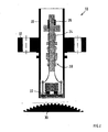
- Fig.1 schematically the structure of a slide protection device 1 of a passenger coach 2 with two biaxial bogies 4, 6 is shown, which is designed for example for a speed up to 200 km / h.
- the anti-slip device 1 has an electronic anti-skid control device 8 as well as sensors 10 on, for example, each wheel 12 of an axle 14 of a bogie 4, 6, by which the instantaneous rotational speed of the respective axle or the respective wheel is detectable.
- a sensor 10 is only shown on one axial side at a time.
- a microprocessor of the electronic Gleitschutz horrinates 8 calculates the actual vehicle or train speed and reduces the predetermined by the arranged in a driver's vehicle, not shown brake control device Brake cylinder pressure in the brake cylinder 15 by means of electro-pneumatic anti-skid valves 16 axle.
- the axles 14 are rotatably supported on the respective bogie 4, 6 by means of two wheelset bearings 18 which are close to the wheels, and 18 of the wheelset bearings 18 Fig.1 However, only one per axis 14 is drawn.
- a wheelset bearing 18 of an axle 14 is an in Fig.2 Assigned explicitly shown combination sensor 10, with which the instantaneous rotational speed of the associated axle 14 and the associated wheel 12, the instantaneous temperature of the respective Radsatzlagers 18 and at least one longitudinal acceleration of the respective Radsatzlagers 18 is measurable.
- a Hall sensor 22 a temperature sensor 24, an acceleration sensor 26 and an evaluation electronics 28 for forming and controlling a rotational speed, a temperature and at least one acceleration signal in a transverse to the wheel axis housing 20 of the combination sensor 10.
- the Hall sensor 22 is opposite to a with the respective axis 14 and the respective wheel 12 mitfitendes pole wheel 30, by the rotation of a signal for the instantaneous rotational speed signal of the respective axis 14 and the respective wheel 12 is generated.
- the housing 20 preferably has an outer flange 32, via which the combination sensor 10 can be detachably fastened directly to the respective wheelset bearing 18.
- the structure-borne noise acting on the wheelset bearing 18, which for example results from flattening on a wheel 12 of the axle 14 or a defective wheelset bearing 18, is transmitted to the housing 20 of the combination sensor 10 and can then be detected by the acceleration sensor 26.
- This is preferably designed for the measurement of longitudinal vibrations in all three spatial axes, but there are also fewer measuring directions can be displayed.
- the prevailing in the relevant wheelset bearing 18 temperature is transmitted to the temperature sensor 24.
- the functions derailment detection, hot runner detection and detection of unstable running behavior are requirements of the TSI for high-speed trains.
- the temperature, rotational speed and acceleration signals of the combination sensors 10 can additionally be used as diagnostic data for the early detection of defective components or track sections of the rails.
- the chassis monitoring control unit 34 is combined with the anti-slip control unit 8 in a structural unit 38.
- This can be realized, for example, in that a housing of the electronic chassis monitoring control unit 34 and a housing of the electronic Gleitschutz horritzs 8 are flanged together.
- the electronic chassis monitoring controller 34 and the electronic anti-skid control device 8 are housed in a common housing 40.
- the chassis monitoring device 36 and the anti-slip device 1 may have at least one common power supply 41, a common interface 42 for communication with an operator and a common interface 44 for communication with a vehicle control system.
- the common interface 44 for communication with the vehicle control system is in particular connected to a vehicle bus 46, for example, to report critical conditions that the chassis monitoring device 36 has detected to a display device.
- a central electronic brake control device of the brake control device is present in this, which controls the braking operations of the entire rail vehicle association and controls.
- a roll monitoring device with an electronic roll monitoring control device is present, which receives the speed signals of the combination sensor 10 and determines whether rolling or turning noise of the wheels of the rail vehicle available.
- the electronic chassis monitoring control unit with the electronic Gleitschutz torture réelle and / or be combined with the electronic brake control unit and / or with the Rollüberwachungs Kunststoff réelle to a structural unit.
Abstract
Description
Die Erfindung geht aus von einer Steuereinrichtung eines Schienenfahrzeugs gemäß den Oberbegriffen der Patentansprüche 1 und 4. Eine solche Steuereinrichtung ist aus der
Gleitschutzeinrichtungen sind nach UIC-Blatt 541-05 für alle Schienenfahrzeuge mit Hochleistungsbremsen der Gattung R vorgeschrieben, wobei jedes Drehgestell getrennt überwacht werden soll. Mittels solcher Gleitschutzeinrichtungen soll das Blockieren der Radsätze beim Bremsen verhindert und ein optimales Ausnutzen des zur Verfügung stehenden Kraftschlusses zwischen Rad und Schiene erzielt werden. Dadurch können Flachstellen an den Rädern vermieden und die Bremswege verkürzt werden. Dazu werden die Drehgeschwindigkeiten aller Achsen einer Fahrzeugeinheit über Drehzahlgeber erfasst. Hieraus berechnet ein Mikroprozessor des elektronischen Gleitschutzsteuergeräts die tatsächliche Fahrzeug- oder Zuggeschwindigkeit und reduziert den durch die Bremssteuerung vorgegebenen Bremszylinderdruck mittels elektropneumatischer Gleitschutzventile achs- oder drehgestellweise. Solche elektronischen Gleitschutzsteuergeräte sind üblicherweise in jedem Reisezugwagen vorhanden.According to UIC sheet 541-05, guards are required for all rail vehicles with R-type heavy-duty brakes, with each bogie to be monitored separately. By means of such Gleitschutzeinrichtungen blocking the wheelsets is prevented during braking and optimum utilization of the available frictional connection between the wheel and rail can be achieved. As a result, flat spots on the wheels can be avoided and the braking distances are shortened. For this purpose, the rotational speeds of all axles of a vehicle unit are recorded by means of a speed sensor. From this, a microprocessor of the electronic Gleitschutzsteuergeräts calculates the actual vehicle or train speed and reduces the predetermined by the brake control brake cylinder pressure by means of electro-pneumatic anti-skid valves axle or bogie way. Such electronic Gleitschutzsteuergeräte are usually present in each passenger car.
Für Fahrzeuge mit einer Höchstgeschwindigkeit von über 200 km/h schreibt die UIC 541-05 neben einer Gleitschutzeinrichtung zusätzlich eine Rollüberwachungseinrichtung vor, welche Drehstörungen von Rädern bzw. das Nichtdrehen von Rädern erfasst und ein entsprechendes Meldesignal aussteuert. Solche Rollüberwachungseinrichtungen umfassen Drehzahlgeber, welche die Drehgeschwindigkeiten der Räder einer Fahrzeugeinheit erfassen und entsprechende Signale ein Rollüberwachungssteuergerät aussteuern.For vehicles with a top speed in excess of 200 km / h, the UIC 541-05 not only includes a non-skid protection device, but also a rolling monitoring device that detects wheel rotation or wheels not turning and controls a corresponding signal. Such roll monitors include tachometers which detect the rotational speeds of the wheels of a vehicle unit and control corresponding signals from a roll monitor controller.
Weiterhin gewinnen heutzutage im Schienenfahrzeugverkehr Fahrwerksüberwachungseinrichtungen immer mehr an Bedeutung. Aus Sicherheitsgründen werden diese Überwachungssysteme in Richtlinien genormt. Beispiele hierfür sind die folgenden Systeme, die aufgrund der Technischen Spezifikationen für die Interoperabilität (TSI) vom Amtsblatt der Europäischen Gemeinschaft für Hochgeschwindigkeitszüge gefordert werden :
- On-Board-Systeme zur Entgleisungsdetektion,
- On-Board-Systeme zur Heißläuferdetektion bzw. zur Lagerschadenerkennung,
- On-Board-Systeme zur Erkennung von instabilem Lauf bzw. von defekten Dämpfern.
- On-board systems for derailment detection,
- On-board systems for hot runner detection or for bearing damage detection,
- On-board systems for detecting unstable running or defective dampers.
Solche Fahrwerksüberwachungseinrichtungen befinden sich bereits in der Anwendung. So wird z.B. im aktuellen ICE ein System zur Erkennung von instabilem Lauf eingesetzt und in neueren automatisch fahrenden Untergrundbahnen kommt ein System zur Entgleisungsdetektion zur Anwendung. Diesen Systemen ist gemeinsam, dass sie funktional als stand-alone-Systeme aufgebaut sind und für sich alleine wirken.Such chassis monitoring devices are already in use. For example, A system for detecting unstable running is used in the current ICE, and a new derailment detection system is being used in newer automatic moving subways. These systems have in common that they are functionally constructed as stand-alone systems and work on their own.
Die Problematik dieser Fahrwerksüberwachungseinrichtungen als separat aufgebaute Systeme (stand-alone-Lösung) besteht in dem relativ hohen Aufwand und Kosten ihrer Realisierung. Denn der Einbau eines solchen Systems erfordert zusätzliche Baugruppen, Sensoren, Verkabelung und Bauraum. Außerdem wird die Komplexität der technischen Ausrüstung erhöht, was sich negativ auf die Zuverlässigkeit auswirkt.The problem of this chassis monitoring devices as a separate system (stand-alone solution) is the relatively high cost and cost of their realization. Because the installation of such a system requires additional modules, sensors, cabling and space. In addition, the complexity of the technical equipment is increased, which has a negative impact on reliability.
Die
Der Erfindung liegt demgegenüber die Aufgabe zugrunde, eine Steuereinrichtung der eingangs erwähnten Art derart weiter zu bilden, dass die oben genannten Nachteile vermieden werden.The invention is based on the object, a control device of the type mentioned in such a way that the above-mentioned disadvantages are avoided.
Erfindungsgemäß wird diese Aufgabe durch die Merkmale der Patentansprüche 1 und 4 gelöst.According to the invention, this object is solved by the features of claims 1 and 4.
Gemäß eines ersten Aspekts der Erfindung ist das elektronische Fahrwerksüberwachungssteuergerät mit dem elektronischen Gleitschutzsteuergerät zu einer baulichen Einheit zusammengefasst, wobei die Fahrwerksüberwachungseinrichtung und die Gleitschutzeinrichtung wenigstens eine gemeinsame Stromversorgung und eine gemeinsame Schnittstelle zur Kommunikation mit einer Bedienperson und eine gemeinsame Schnittstelle zur Kommunikation mit einem Fahrzeugleitsystem aufweisen und der Gleitschutzsensor ein Kombinationssensor ist, welcher außer dem Signal für die Drehgeschwindigkeit wenigstens eines Rades oder einer Achse ein Signal für die Temperatur eines Radsatzlagers und ein Schwingungssignal für am Radsatzlager herrschende Schwingungen an das Fahrwerküberwachungssteuergerät aussteuert, um die Drehgeschwindigkeits-, Temperatur- und Beschleunigungssignale des Kombinationssensors zusätzlich als Diagnosedaten zur frühzeitigen Erkennung defekter Bauteile oder Streckenabschnitte der Schienen heranzuziehen.According to a first aspect of the invention, the electronic chassis monitoring control unit is combined with the electronic anti-skid control device to form a structural unit, wherein the Chassis monitoring device and the anti-slip device have at least a common power supply and a common interface for communication with an operator and a common interface for communication with a vehicle control system and the anti-skid sensor is a combination sensor, which in addition to the signal for the rotational speed of at least one wheel or an axle signal for the temperature of a wheelset bearing and an oscillation signal for prevailing at the wheelset vibration to the chassis monitoring control unit controls to additionally use the rotational speed, temperature and acceleration signals of the combination sensor as diagnostic data for early detection of defective components or track sections of the rails.
Gemäß eines weiteren Aspekts der Erfindung ist das elektronische Fahrwerksüberwachungssteuergerät mit dem elektronischen Rollüberwachungssteuergerät zu einer baulichen Einheit zusammengefasst, wobei die Fahrwerksüberwachungseinrichtung und die Rollüberwachungseinrichtung wenigstens eine gemeinsame Stromversorgung und eine gemeinsame Schnittstelle zur Kommunikation mit einer Bedienperson und eine gemeinsame Schnittstelle zur Kommunikation mit einem Fahrzeugleitsystem aufweisen und der Rollüberwachungssensor ein Kombinationssensor ist, welcher außer einem Signal für die Drehgeschwindigkeit wenigstens eines Rades oder einer Achse ein Signal für die Temperatur eines Radsatzlagers und ein Schwingungssignal für die am Radsatzlager herrschende Schwingungen an das Fahrwerküberwachungssteuergerät aussteuert, um die Drehgeschwindigkeits-, Temperatur- und Beschleunigungssignale des Kombinationssensors als Diagnosedaten zur frühzeitigen Erkennung defekter Bauteile oder Streckenabschnitte der Schienen heranzuziehen.According to a further aspect of the invention, the electronic chassis monitoring control unit is combined with the electronic rolling surveillance control unit to form a structural unit, wherein the chassis monitoring device and the roll monitoring device have at least one common power supply and a common interface for communication with an operator and a common interface for communication with a vehicle control system and the roll monitoring sensor is a combination sensor which, in addition to a signal for the rotational speed of at least one wheel or axle, outputs a signal for the temperature of a wheelset bearing and a vibration signal for the vibrations prevailing at the wheelset bearing to the chassis monitoring control unit to determine the rotational speed, temperature and acceleration signals of the Combination sensor as diagnostic data for the early detection of defective components or Streckenabsc hnitte of the rails.
Das Fahrwerksüberwachungssteuergerät benötigt insbesondere die Drehgeschwindigkeitssignale der Radachsen oder der Räder, um die Überwachungsfunktion auszuführen. Diese Signale können mit geringem Aufwand intern weitergeleitet werden, wenn das Fahrwerksüberwachungssteuergerät mit dem Gleitschutzsteuergerät oder mit dem Rollüberwachungssteuergerät zu einer Baueinheit zusammengefasst bzw. in integrierter Bauweise vorhanden ist. Darüber hinaus stehen diverse Zustandssignale über das aktuelle Brems- und Fahrverhalten den im Überwachungssteuergerät implementierten Überwachungsalgorithmen direkt zur Verfügung und ermöglichen eine effektivere Diagnose.Specifically, the chassis monitoring control apparatus requires the rotational speed signals of the wheel axles or the wheels to perform the monitoring function. These signals can be forwarded internally with little effort when the chassis monitoring control unit with the Gleitschutzsteuergerät or with the roll monitoring control unit combined to form a unit or is present in an integrated design. In addition, various status signals about the current braking and driving behavior are directly available to the monitoring algorithms implemented in the monitoring control unit and enable a more effective diagnosis.
Die bauliche Einheit bietet weiterhin die Möglichkeit, bestimmte Systemkomponenten gemeinsam zu nutzen, beispielsweise eine gemeinsame Stromversorgung, eine gemeinsame Schnittstelle zur Kommunikation mit einer Bedienperson und eine gemeinsame Schnittstelle zur Kommunikation mit dem Fahrzeugleitsystem. Dies reduziert den gerätetechnischen Aufwand. Bei Anwendung einer leistungsfähigeren Rechnereinheit ist auch das parallele Verarbeiten von Gleitschutz-, Rollüberwachungs- und Fahrwerksüberwachungsalgorithmen denkbar. Infolgedessen werden Baugruppen von verschiedenen Einrichtungen kostengünstig gemeinsam genutzt. Die gemeinsame Schnittstelle zur Kommunikation mit dem Fahrzeugleitsystem ist insbesondere an einen Fahrzeugbus angeschlossen, um beispielsweise kritische Zustände, welche von der Fahrwerksüberwachungseinrichtung detektiert wurden, an eine Anzeigeeinrichtung zu melden.The structural unit also offers the possibility of sharing certain system components, for example a common power supply, a common interface for communication with an operator and a common interface for communication with the vehicle control system. This reduces the equipment costs. When using a more powerful computer unit, the parallel processing of anti-skid, roll monitoring and chassis monitoring algorithms is also conceivable. As a result, assemblies of various devices are shared inexpensively. The common interface for communication with the vehicle control system is in particular connected to a vehicle bus, for example, to report critical conditions that were detected by the chassis monitoring device to a display device.
Nicht zuletzt kann der Einsatz der Fahrwerksüberwachungseinrichtung zur Diagnose und Früherkennung von schadhaften Bauteilen, kritischen Zuständen bzw. sonstigen Fehlern, wie beispielsweise die Erkennung von Flachstellen an Rädern oder die Früherkennung von Lagerschäden eine frühzeitige und zustandsorientierte Wartung ermöglichen. Ziel sind dabei geringere Stillstandszeiten, eine bessere Ausnutzung von Bauteilen und damit die Einsparung von Kosten.Last but not least, the use of the chassis monitoring device for the diagnosis and early detection of defective components, critical conditions or other errors, such as the detection of flats on wheels or the early detection of bearing damage can provide early and condition-based maintenance. The aim is to reduce downtimes, make better use of components and thus save on costs.
Durch die in den Unteransprüchen aufgeführten Maßnahmen sind vorteilhafte Weiterbildungen und Verbesserungen der in den unabhängigen Ansprüchen angegebenen Erfindung möglich.The measures listed in the dependent claims advantageous refinements and improvements of the invention specified in the independent claims are possible.
Besonders bevorzugt ist der Kombinationssensor vorzugsweise direkt am zu überwachenden Radsatzlager oder in der unmittelbaren Nähe des Radsatzlagers angeordnet.Particularly preferably, the combination sensor is preferably arranged directly on the wheelset bearing to be monitored or in the immediate vicinity of the wheelset bearing.
Ein Ausführungsbeispiel der Erfindung ist in der Zeichnung dargestellt und in der nachfolgenden Beschreibung näher erläutert. In der Zeichnung zeigt:
- Fig.1
- eine schematische Darstellung einer Gleitschutzeinrichtung eines Reisezugwagens gemäß einer bevorzugten Ausführungsform;
- Fig.2
- eine schematische Querschnittsdarstellung eines in der Gleitschutzeinrichtung verwendeten Kombinationssensors von
Fig.1 ;
- Fig.1
- a schematic representation of a Gleitschutzeinrichtung a passenger car according to a preferred embodiment;
- Fig.2
- a schematic cross-sectional view of a combination sensor used in the Gleitschutzeinrichtung of
Fig.1 ;
In
Die Gleitschutzeinrichtung 1 verfügt über ein elektronisches Gleitschutzsteuergerät 8 sowie über Sensoren 10 an beispielsweise jedem Rad 12 einer Achse 14 eines Drehgestells 4, 6, durch welche die momentane Drehgeschwindigkeit der jeweiligen Achse bzw. des jeweiligen Rades detektierbar ist. In
Je einem Radsatzlager 18 einer Achse 14 ist ein in
Gemäß einer besonders bevorzugten Ausführungsform sind in einem sich quer zur Radachse erstreckenden Gehäuse 20 des Kombinationssensors 10 ein Hallsensor 22, ein Temperatursensor 24, ein Beschleunigungssensor 26 sowie eine Auswerteelektronik 28 zur Bildung und Aussteuerung eines Drehgeschwindigkeits-, eines Temperatur- und wenigstens eines Beschleunigungssignals. Dem Hallsensor 22 liegt ein mit der jeweiligen Achse 14 bzw. mit dem jeweiligen Rad 12 mitdrehendes Polrad 30 gegenüber, durch dessen Drehung ein Signal für die momentane Drehgeschwindigkeitssignal der jeweiligen Achse 14 bzw. des jeweiligen Rades 12 erzeugt wird. Das Gehäuse 20 weist vorzugsweise einen Außenflansch 32 auf, über welchen der Kombinationssensor 10 unmittelbar an dem betreffenden Radsatzlager 18 lösbar befestigt werden kann. Dadurch wird der auf das Radsatzlager 18 einwirkende Körperschall, welcher beispielsweise von Abflachungen an einem Rad 12 der Achse 14 oder einem defekten Radsatzlager 18 herrührt, auf das Gehäuse 20 des Kombinationssensors 10 übertragen und kann dann vom Beschleunigungssensor 26 detektiert werden. Dieser ist vorzugsweise zur Messungen von Längsschwingungen in allen drei Raumachsen ausgebildet, es sind aber auch weniger Messrichtungen darstellbar. Auf demselben Wege wird die in dem betreffenden Radsatzlager 18 herrschende Temperatur auf den Temperatursensor 24 übertragen.According to a particularly preferred embodiment, a
Diese Signale werden von der Auswerteelektronik 28 unter anderem an ein Fahrwerksüberwachungssteuergerät 34 einer Fahrwerksüberwachungseinrichtung 36 ausgesteuert, welches folgende Überwachungsfunktionen ausführen kann :
- Warm- und Heißläuferdetektion des jeweiligen Radsatzlagers 18 durch Temperaturüberwachung des
Radsatzlagers 18; - Lagerschadenerkennung des jeweiligen Radsatzlagers 18 durch entsprechende Schwingungssignale;
- Erkennung von instabilem Lauf bzw. von defekten Dämpfern im Fahrwerk durch entsprechende Schwingungssignale;
- Entgleisungsdetektion;
- Detektion von Flachstellen und unrunden Rädern 12 durch entsprechende Schwingungssignale.
- Hot and hot rotor detection of the respective wheelset bearing 18 by monitoring the temperature of the
wheelset bearing 18; - Bearing damage detection of the respective wheelset bearing 18 by means of corresponding vibration signals;
- Detection of unstable running or defective dampers in the chassis by corresponding vibration signals;
- Derailment detection;
- Detection of flat and
non-circular wheels 12 by corresponding vibration signals.
Die Funktionen Entgleisungsdetektion, Heißläufererkennung sowie Detektion von instabilem Laufverhalten sind Forderungen bzw. Empfehlungen der TSI für Hochgeschwindigkeitszüge. Die Temperatur-, Drehgeschwindigkeits- und Beschleunigungssignale der Kombinationssensoren 10 können zusätzlich als Diagnosedaten zur frühzeitigen Erkennung defekter Bauteile oder Streckenabschnitte der Schienen herangezogen werden.The functions derailment detection, hot runner detection and detection of unstable running behavior are requirements of the TSI for high-speed trains. The temperature, rotational speed and acceleration signals of the
Das Fahrwerksüberwachungssteuergerät 34 ist mit dem Gleitschutzsteuergerät 8 in einer Baueinheit 38 zusammengefasst. Dies kann beispielsweise dadurch realisiert sein, dass ein Gehäuse des elektronischen Fahrwerksüberwachungssteuergeräts 34 und ein Gehäuse des elektronischen Gleitschutzsteuergeräts 8 aneinandergeflanscht sind. Bevorzugt sind jedoch das elektronische Fahrwerksüberwachungssteuergerät 34 und das elektronische Gleitschutzsteuergerät 8 in einem gemeinsamen Gehäuse 40 untergebracht.The chassis
Die Fahrwerksüberwachungseinrichtung 36 und die Gleitschutzeinrichtung 1 können wenigstens eine gemeinsame Stromversorgung 41, eine gemeinsame Schnittstelle 42 zur Kommunikation mit einer Bedienperson und eine gemeinsame Schnittstelle 44 zur Kommunikation mit einem Fahrzeugleitsystem aufweisen. Die gemeinsame Schnittstelle 44 zur Kommunikation mit dem Fahrzeugleitsystem ist insbesondere an einen Fahrzeugbus 46 angeschlossen, um beispielsweise kritische Zustände, welche die Fahrwerksüberwachungseinrichtung 36 detektiert hat, an eine Anzeigeeinrichtung zu melden.The
Falls das betreffende Schienenfahrzeug kein Reisezugwagen 2, sondern das Führerfahrzeug des Schienenfahrzeugverbandes ist, ist in diesem ein zentrales elektronisches Bremssteuergerät der Bremssteuereinrichtung vorhanden, welches die Bremsvorgänge des gesamten Schienenfahrzeugverbandes steuert und regelt.If the rail vehicle concerned is not a passenger coach 2, but the driver's vehicle of the railway vehicle association, a central electronic brake control device of the brake control device is present in this, which controls the braking operations of the entire rail vehicle association and controls.
Falls ein Reisezugwagen oder ein Führerfahrzeug für Geschwindigkeiten über 200 km/h ausgelegt ist, ist neben der Gleitschutzeinrichtung 1 zusätzlich eine Rollüberwachungseinrichtung mit einem elektronischen Rollüberwachungsteuergerät vorhanden, welches die Drehzahlsignale des Kombinationssensors 10 empfängt und daraus ermittelt, ob Roll- oder Drehstörungen der Räder des Schienenfahrzeugs vorliegen.If a passenger coach or a driver's vehicle is designed for speeds in excess of 200 km / h, in addition to the anti-slip device 1, a roll monitoring device with an electronic roll monitoring control device is present, which receives the speed signals of the
Je nach Ausstattung und Art des Schienenfahrzeugs soll dann das elektronische Fahrwerksüberwachungssteuergerät mit dem elektronischen Gleitschutzsteuergerät und/oder mit dem elektronischen Bremssteuergerät und/oder mit dem Rollüberwachungssteuergerät zu einer baulichen Einheit zusammengefasst sein.Depending on the equipment and type of rail vehicle then the electronic chassis monitoring control unit with the electronic Gleitschutzsteuergerät and / or be combined with the electronic brake control unit and / or with the Rollüberwachungssteuergerät to a structural unit.
BezugszahlenlisteLIST OF REFERENCE NUMBERS
- 11
- Gleitschutzeinrichtunganti-skid device
- 22
- Reisezugwagencoaches
- 44
- Drehgestellbogie
- 66
- Drehgestellbogie
- 88th
- Gleitschutzsteuergerätanti-skid
- 1010
- Kombinationssensorcombination sensor
- 1212
- Radwheel
- 1414
- Achseaxis
- 1515
- Bremszylinderbrake cylinder
- 1616
- Gleitschutzventildump valve
- 1818
- Radsatzlagerwheelset bearings
- 2020
- Gehäusecasing
- 2222
- HallsensorHall sensor
- 2424
- Temperatursensortemperature sensor
- 2626
- Beschleunigungssensoraccelerometer
- 2828
- Auswerteelektronikevaluation
- 3030
- Polradflywheel
- 3232
- Außenflanschouter flange
- 3434
- FahrwerksüberwachungssteuergerätGear monitoring control unit
- 3636
- FahrwerksüberwachungseinrichtungGear monitoring device
- 3838
- Baueinheitunit
- 4040
- Gehäusecasing
- 4141
- Stromversorgungpower supply
- 4242
- Schnittstelleinterface
- 4444
- Schnittstelleinterface
- 4646
- Fahrzeugbusvehicle bus
Claims (11)
- Control device of a rail vehicle (2) with an anti-skid device (1) which controls the wheel slip of the wheels (12) of at least one axle (14) as a function of at least one rotational speed signal supplied to an electronic anti-skid control unit (8) by an anti-skid sensor (10) and with a rolling gear monitoring device (36) for monitoring and/or for diagnosing the rolling gear with respect to critical states and damage such as, for example, derailment, overheated bearings, unstable running and the like, comprising an electronic rolling gear monitoring control unit (34), characterised in thata) the electronic rolling gear monitoring control unit (34) is combined with the electronic anti-skid control unit (8) to form one structural unit (38), whereinb) the rolling gear monitoring device (36) and the anti-skid device (1) have at least one common power supply (41) and one common interface (42) for communicating with an operator and one common interface (44) for communicating with a vehicle control system, and whereinc) the anti-skid sensor is a combination sensor (10) which, apart from the signal for the rotational speed of at least one wheel or axle, modulates a signal for the temperature of a wheel set bearing (18) and an oscillation signal for oscillations occurring at the wheel set bearing (18) to the - rolling gear monitoring control unit (34), in order to include the rotational speed, temperature and acceleration signals of the combination sensor (10) as additional diagnostic data for the early detection of faulty components or rail sections.
- Control device according to claim 1, characterised in that a housing of the electronic rolling gear monitoring control unit and a housing of the electronic anti-skid control unit are connected to one another by flanges.
- Control device according to claim 1, characterised in that at least part of the electronic rolling gear monitoring control unit (34) and of the electronic anti-skid control unit (8) are accommodated in a common housing (40).
- Control device of a rail vehicle (2) with a roll monitoring device comprising an electronic roll monitoring control unit and at least one roll monitoring sensor (10) for sensing the rotational speed of at least one of the wheels in the form of a rotational speed signal, and with a rolling gear monitoring device (36) for monitoring and/or for diagnosing the rolling gear with respect to critical states and damage such as, for example, derailment, overheated bearings, unstable running and the like, comprising an electronic rolling gear monitoring control unit (34), characterised in thata) the electronic rolling gear monitoring control unit (34) is combined with the electronic roll monitoring control unit to form one structural unit (38), whereinb) the rolling gear monitoring device (36) and the roll monitoring device have at least one common power supply (41) and one common interface (42) for communicating with an operator and one common interface (44) for communicating with a vehicle control system, and whereinc) the roll monitoring sensor is a combination sensor (10) which, apart from the signal for the rotational speed of at least one wheel or axle, modulates a signal for the temperature of a wheel set bearing (18) and an oscillation signal for oscillations occurring at the wheel set bearing (18) to the rolling gear monitoring control unit (34), in order to include the rotational speed, temperature and acceleration signals of the combination sensor (10) as diagnostic data for the early detection of components or rail sections.
- Control device according to claim 4, characterised in that a housing of the electronic rolling gear monitoring control unit and a housing of the roll monitoring control unit are connected to one another by flanges.
- Control device according to claim 4, characterised in that at least part of the electronic rolling gear monitoring control unit (34) and of the roll monitoring control unit are accommodated in a common housing (40).
- Control device according to any of the preceding claims, characterised in that the combination sensor (10) is arranged directly on the wheel set bearing (18) or in the immediate vicinity of the wheel set bearing (18).
- Control device according to any of the preceding claims, characterised in that the rolling gear monitoring control unit (34) evaluates the rotational speed signal of the roll monitoring sensor (10) and/or of the anti-skid sensor (10).
- Control device according to any of the preceding claims, characterised in that the common interface (44) for communicating with a vehicle control system is connected to a vehicle bus (46).
- Control device according to claim 9, characterised in that the vehicle control system comprises a display device for signalling critical states which the rolling gear monitoring device (38) has detected.
- Rail vehicle including a control device according to at least one of the preceding claims.
Priority Applications (2)
| Application Number | Priority Date | Filing Date | Title |
|---|---|---|---|
| SI200631086T SI2050639T1 (en) | 2005-03-02 | 2006-02-28 | Control device for a rail vehicle |
| PL09000488T PL2050639T3 (en) | 2005-03-02 | 2006-02-28 | Control device for a rail vehicle |
Applications Claiming Priority (2)
| Application Number | Priority Date | Filing Date | Title |
|---|---|---|---|
| DE102005010118A DE102005010118A1 (en) | 2005-03-02 | 2005-03-02 | Control device of a rail vehicle |
| EP06707318A EP1855928B1 (en) | 2005-03-02 | 2006-02-28 | Control unit for a rail vehicle |
Related Parent Applications (2)
| Application Number | Title | Priority Date | Filing Date |
|---|---|---|---|
| EP06707318A Division EP1855928B1 (en) | 2005-03-02 | 2006-02-28 | Control unit for a rail vehicle |
| EP06707318.9 Division | 2006-02-28 |
Publications (2)
| Publication Number | Publication Date |
|---|---|
| EP2050639A1 EP2050639A1 (en) | 2009-04-22 |
| EP2050639B1 true EP2050639B1 (en) | 2011-05-18 |
Family
ID=36540255
Family Applications (2)
| Application Number | Title | Priority Date | Filing Date |
|---|---|---|---|
| EP06707318A Active EP1855928B1 (en) | 2005-03-02 | 2006-02-28 | Control unit for a rail vehicle |
| EP09000488A Active EP2050639B1 (en) | 2005-03-02 | 2006-02-28 | Control device for a rail vehicle |
Family Applications Before (1)
| Application Number | Title | Priority Date | Filing Date |
|---|---|---|---|
| EP06707318A Active EP1855928B1 (en) | 2005-03-02 | 2006-02-28 | Control unit for a rail vehicle |
Country Status (15)
| Country | Link |
|---|---|
| US (1) | US8276995B2 (en) |
| EP (2) | EP1855928B1 (en) |
| JP (1) | JP5522898B2 (en) |
| KR (1) | KR101248715B1 (en) |
| CN (2) | CN102700533B (en) |
| AT (2) | ATE553014T1 (en) |
| DE (1) | DE102005010118A1 (en) |
| DK (2) | DK1855928T3 (en) |
| ES (2) | ES2384467T3 (en) |
| HK (1) | HK1177181A1 (en) |
| PL (2) | PL2050639T3 (en) |
| PT (2) | PT2050639E (en) |
| RU (1) | RU2392140C2 (en) |
| SI (1) | SI2050639T1 (en) |
| WO (1) | WO2006092263A1 (en) |
Cited By (3)
| Publication number | Priority date | Publication date | Assignee | Title |
|---|---|---|---|---|
| DE102012217708A1 (en) | 2012-09-28 | 2014-04-03 | Siemens Aktiengesellschaft | Device for a rail vehicle |
| WO2014048737A1 (en) | 2012-09-28 | 2014-04-03 | Siemens Aktiengesellschaft | Device for a rail vehicle |
| DE102012217721A1 (en) | 2012-09-28 | 2014-04-03 | Siemens Aktiengesellschaft | Device for a rail vehicle |
Families Citing this family (33)
| Publication number | Priority date | Publication date | Assignee | Title |
|---|---|---|---|---|
| DE102006030312A1 (en) * | 2006-06-30 | 2008-01-03 | Schaeffler Kg | Sensor unit for a wheel set bearing |
| DE102007024066B4 (en) * | 2007-05-22 | 2017-06-14 | Knorr-Bremse Systeme für Schienenfahrzeuge GmbH | Bogie of a rail vehicle with a device for fault monitoring of suspension components |
| DE102007024065B8 (en) * | 2007-05-22 | 2009-05-14 | Knorr-Bremse Systeme für Schienenfahrzeuge GmbH | Device and method for fault monitoring of chassis components of rail vehicles |
| DE102008032715B4 (en) | 2008-07-11 | 2012-03-08 | Knorr-Bremse Systeme für Schienenfahrzeuge GmbH | Electropneumatic brake device of a rail vehicle |
| DE102008045712A1 (en) * | 2008-09-04 | 2011-04-07 | Knorr-Bremse Systeme für Schienenfahrzeuge GmbH | Electropneumatic braking device and method for operating the same |
| DE102009016986A1 (en) * | 2009-04-08 | 2010-10-14 | Knorr-Bremse Systeme für Schienenfahrzeuge GmbH | Method and device for braking force control |
| PL2475563T3 (en) | 2009-09-09 | 2014-09-30 | Knorr Bremse Systeme | Method and device for estimating the temperature of an axle bearing of a wheelset of a rail vehicle |
| US20110115284A1 (en) * | 2009-11-13 | 2011-05-19 | Head Thomas S | Wheel slip protection system |
| DE102009053801B4 (en) * | 2009-11-18 | 2019-03-21 | Knorr-Bremse Systeme für Schienenfahrzeuge GmbH | Method and device for condition monitoring at least one wheelset bogie of a rail vehicle |
| EA016570B1 (en) * | 2010-04-15 | 2012-05-30 | Павел Валерьевич Горюнов | System of monitoring wheel's state of railway transport and antiskid control device |
| DE102010049303A1 (en) * | 2010-10-22 | 2012-04-26 | Knorr-Bremse Systeme für Schienenfahrzeuge GmbH | Method for controlling a sliding friction-controlled friction brake system of a rail vehicle |
| DE102011011443A1 (en) * | 2011-02-16 | 2012-08-16 | Voith Patent Gmbh | Method for operating a rail-bound vehicle |
| DE102011006002A1 (en) * | 2011-03-23 | 2012-09-27 | Siemens Aktiengesellschaft | Actuator for a braking system of a rail vehicle |
| CN102343897B (en) * | 2011-07-13 | 2013-04-17 | 铁道部运输局 | Braking control system of rail transit vehicle and anti-skidding control plate for braking control system of rail transit vehicle |
| CN102343898B (en) * | 2011-07-13 | 2013-05-22 | 铁道部运输局 | Wheel anti-skidding protection control method during hybrid braking of rail transit vehicle and system thereof |
| DE102011113084A1 (en) * | 2011-09-09 | 2013-03-14 | Knorr-Bremse Systeme für Schienenfahrzeuge GmbH | Brake control device for a brake system of a rail vehicle, brake system, rail vehicle and method for performing a state analysis of a rail vehicle |
| DE102011113120B4 (en) * | 2011-09-09 | 2020-03-19 | Knorr-Bremse Systeme für Schienenfahrzeuge GmbH | Brake control device for a brake system of a rail vehicle, brake system, rail vehicle and method for controlling a brake system |
| DE102011089653A1 (en) * | 2011-12-22 | 2013-06-27 | Siemens Aktiengesellschaft | Method and arrangement for monitoring a brake system of a brake arrangement of a rail vehicle |
| DE102012202120A1 (en) * | 2012-02-13 | 2013-08-14 | Siemens Aktiengesellschaft | Anti-skid system of a braking device |
| DE102013201289B4 (en) | 2013-01-28 | 2018-03-15 | Siemens Aktiengesellschaft | Method for detecting a swing in a rail vehicle |
| JP6128594B2 (en) * | 2013-05-29 | 2017-05-17 | 曙ブレーキ工業株式会社 | Derailment sign detection system, control device, derailment sign detection method, and derailment sign detection program |
| FR3014400B1 (en) * | 2013-12-11 | 2016-02-05 | Alstom Transport Sa | LAND VEHICLE GUIDE COMPRISING A DEVICE FOR MANAGING A DERAILMENT OF THE VEHICLE, AND METHOD FOR MANAGING THE DERAILMENT THEREOF |
| GB2533940A (en) * | 2015-01-07 | 2016-07-13 | Barnbrook Systems Ltd | Monitor |
| WO2016119964A1 (en) * | 2015-01-30 | 2016-08-04 | Siemens Aktiengesellschaft | Method for determining a torsional moment |
| DE102016125193B4 (en) * | 2016-12-21 | 2020-12-03 | Knorr-Bremse Systeme für Schienenfahrzeuge GmbH | Method for maintaining the total braking force of a train, taking into account the available adhesion ratios |
| DE102017119994B4 (en) * | 2017-08-31 | 2020-08-27 | Knorr-Bremse Systeme für Schienenfahrzeuge GmbH | Method and device for determining braking-relevant actual values of a rail vehicle for the implementation of deceleration-controlled braking with central sensors |
| DE102017119991B4 (en) * | 2017-08-31 | 2020-11-26 | Knorr-Bremse Systeme für Schienenfahrzeuge GmbH | Method and device for determining braking-relevant actual values of a rail vehicle for performing deceleration-controlled braking with distributed sensors |
| KR102097520B1 (en) | 2018-11-23 | 2020-04-06 | 유진기공산업주식회사 | Wheel rotation monitoring equipment for railway |
| IT201900003423A1 (en) * | 2019-03-08 | 2020-09-08 | Faiveley Transport Italia Spa | Supervisor device for monitoring the operation of an anti-skid device of a railway braking system |
| DE102019213586A1 (en) * | 2019-09-06 | 2021-03-11 | Siemens Mobility GmbH | Method, device and rail vehicle |
| CN113060113B (en) * | 2021-03-10 | 2022-02-15 | 交控科技股份有限公司 | Safe standby brake anti-skid system and method for railway vehicle-mounted brake control |
| CN114152451B (en) * | 2021-11-10 | 2023-06-06 | 柳州铁道职业技术学院 | Steering power detection device and method for quick truck bogie |
| KR20230081083A (en) | 2021-11-30 | 2023-06-07 | 한국철도기술연구원 | Diagnostic device for brake caliper of railway vehicles |
Family Cites Families (34)
| Publication number | Priority date | Publication date | Assignee | Title |
|---|---|---|---|---|
| US3059107A (en) * | 1959-05-08 | 1962-10-16 | Raymond N Mccool | Railroad rolling stock bearing temperature monitor |
| US4027753A (en) * | 1976-04-15 | 1977-06-07 | The B.F. Goodrich Company | In-axle vehicle wheel speed sensing device |
| JPS61199401A (en) * | 1985-02-27 | 1986-09-03 | Nippon Air Brake Co Ltd | Skid detecting method |
| DE3809886C2 (en) | 1988-03-24 | 1997-01-16 | Teves Gmbh Alfred | Automotive sensor |
| DE3824985A1 (en) * | 1988-07-22 | 1990-01-25 | Knorr Bremse Ag | BRAKE DEVICE FOR RAIL VEHICLES OR TRAIN |
| US5201834A (en) * | 1989-04-05 | 1993-04-13 | Inventio Ag | Method for the testing and monitoring of brakes in rail vehicles |
| DE4137546C2 (en) | 1991-11-12 | 1994-01-20 | Mannesmann Ag | Method and device for determining the actual speed of travel in rail vehicles |
| US5411323A (en) * | 1993-03-17 | 1995-05-02 | Sumitomo Precision Products Co., Ltd. | Automatic brake control apparatus and a brake pressure control valve |
| DE9321190U1 (en) * | 1993-09-13 | 1998-01-15 | Duerrwaechter E Dr Doduco | Component set for a housing made of plastic for receiving electrical components |
| DE19603193C1 (en) * | 1996-01-31 | 1997-04-03 | Wilke Richard | Electrical motor-driven brake actuator for rail-borne vehicle use |
| DE19610664C2 (en) * | 1996-03-08 | 1998-02-19 | Mannesmann Ag | Brake cylinder device for rail vehicles |
| JP4019399B2 (en) | 1997-03-31 | 2007-12-12 | マツダ株式会社 | Electronic equipment |
| JPH11115720A (en) * | 1997-10-15 | 1999-04-27 | Hino Motors Ltd | Estimation device of road surface friction coefficient |
| WO1999026820A1 (en) | 1997-11-22 | 1999-06-03 | Continental Teves Ag & Co. Ohg | Electromechanical brake system |
| US6390779B1 (en) | 1998-07-22 | 2002-05-21 | Westinghouse Air Brake Technologies Corporation | Intelligent air compressor operation |
| AU764556B2 (en) * | 1998-10-23 | 2003-08-21 | Knorr-Bremse Systeme Fur Schienenfahrzeuge Gmbh | Brake system for railway vehicles |
| DE10026685B4 (en) * | 2000-05-30 | 2005-10-20 | Knorr Bremse Systeme | Brake system for vehicles equipped with an ABS system or anti-skid system |
| JP3897969B2 (en) | 2000-09-04 | 2007-03-28 | 本田技研工業株式会社 | Vehicle travel control device |
| AT410921B (en) * | 2000-10-12 | 2003-08-25 | Siemens Sgp Verkehrstech Gmbh | METHOD AND DEVICE FOR DETECTING DAMAGE ON WHEELS OF A RAIL VEHICLE |
| JP2002295464A (en) * | 2001-03-30 | 2002-10-09 | Nsk Ltd | Abnormality detection device of rolling bearing unit |
| DE50113069D1 (en) * | 2000-12-19 | 2007-11-08 | Knorr Bremse Systeme | ELECTROMECHANICAL BRAKE COUPLING |
| US20020088673A1 (en) * | 2001-01-05 | 2002-07-11 | General Electric Company | Railcar anti-skid brakes |
| DE10146093A1 (en) * | 2001-09-19 | 2003-04-03 | Bosch Gmbh Robert | Electronic module, especially for use in motor vehicle, has first plug with which module can be plugged onto holder and second plug to which further electronic module can be connected |
| EP1436634A1 (en) * | 2001-10-05 | 2004-07-14 | Continental Teves AG & Co. oHG | Acceleration sensor for motor vehicles |
| JP2003160043A (en) * | 2001-11-22 | 2003-06-03 | Nabco Ltd | Brake device for rolling stock |
| JP3874110B2 (en) | 2002-08-30 | 2007-01-31 | 日本精工株式会社 | Abnormality diagnosis system |
| US7184930B2 (en) * | 2002-08-30 | 2007-02-27 | Nsk Ltd. | Method and device for monitoring status of mechanical equipment and abnormality diagnosing device |
| CN1490208A (en) * | 2002-10-14 | 2004-04-21 | 北京理工大学 | Rolling bearing fault testing method and apparatus for wagon |
| DE20220772U1 (en) * | 2002-11-13 | 2004-04-29 | Siemens Ag | Electronic controller, especially unit carrier with plug positions, has at least one roller fan arranged between the rear wall and connector plane so that upward or downward air flow can be produced |
| JP3841048B2 (en) * | 2002-12-26 | 2006-11-01 | 三菱ふそうトラック・バス株式会社 | Integrated control device for vehicle |
| KR100521169B1 (en) * | 2002-12-27 | 2005-10-12 | 현대자동차주식회사 | A method for controlling rollover of vehicle |
| GB2402983B (en) * | 2003-06-18 | 2006-07-19 | Westinghouse Brakes | Digital databus |
| DE10332034B4 (en) * | 2003-07-15 | 2009-04-09 | Kes Keschwari Electronic Systems Gmbh & Co. Kg | Device for braking and monitoring a rail vehicle with or without bogies |
| US7018004B2 (en) * | 2003-12-18 | 2006-03-28 | Ford Global Technologies, Llc | System and method for brake pre-charging |
-
2005
- 2005-03-02 DE DE102005010118A patent/DE102005010118A1/en not_active Ceased
-
2006
- 2006-02-28 ES ES06707318T patent/ES2384467T3/en active Active
- 2006-02-28 ES ES09000488T patent/ES2364411T3/en active Active
- 2006-02-28 JP JP2007557405A patent/JP5522898B2/en active Active
- 2006-02-28 EP EP06707318A patent/EP1855928B1/en active Active
- 2006-02-28 DK DK06707318.9T patent/DK1855928T3/en active
- 2006-02-28 DK DK09000488.8T patent/DK2050639T3/en active
- 2006-02-28 KR KR1020077022242A patent/KR101248715B1/en active IP Right Grant
- 2006-02-28 PT PT09000488T patent/PT2050639E/en unknown
- 2006-02-28 PT PT06707318T patent/PT1855928E/en unknown
- 2006-02-28 CN CN201210178354.6A patent/CN102700533B/en active Active
- 2006-02-28 AT AT06707318T patent/ATE553014T1/en active
- 2006-02-28 US US11/817,484 patent/US8276995B2/en active Active
- 2006-02-28 AT AT09000488T patent/ATE509813T1/en active
- 2006-02-28 PL PL09000488T patent/PL2050639T3/en unknown
- 2006-02-28 EP EP09000488A patent/EP2050639B1/en active Active
- 2006-02-28 RU RU2007136348/11A patent/RU2392140C2/en active
- 2006-02-28 WO PCT/EP2006/001810 patent/WO2006092263A1/en active Application Filing
- 2006-02-28 CN CNA2006800066750A patent/CN101132961A/en active Pending
- 2006-02-28 PL PL06707318T patent/PL1855928T3/en unknown
- 2006-02-28 SI SI200631086T patent/SI2050639T1/en unknown
-
2013
- 2013-04-02 HK HK13104056.8A patent/HK1177181A1/en not_active IP Right Cessation
Cited By (4)
| Publication number | Priority date | Publication date | Assignee | Title |
|---|---|---|---|---|
| DE102012217708A1 (en) | 2012-09-28 | 2014-04-03 | Siemens Aktiengesellschaft | Device for a rail vehicle |
| WO2014048737A1 (en) | 2012-09-28 | 2014-04-03 | Siemens Aktiengesellschaft | Device for a rail vehicle |
| DE102012217830A1 (en) | 2012-09-28 | 2014-04-03 | Siemens Aktiengesellschaft | Device for a rail vehicle |
| DE102012217721A1 (en) | 2012-09-28 | 2014-04-03 | Siemens Aktiengesellschaft | Device for a rail vehicle |
Also Published As
| Publication number | Publication date |
|---|---|
| RU2392140C2 (en) | 2010-06-20 |
| PT1855928E (en) | 2012-06-27 |
| JP5522898B2 (en) | 2014-06-18 |
| PL2050639T3 (en) | 2011-10-31 |
| PL1855928T3 (en) | 2012-09-28 |
| US20080156944A1 (en) | 2008-07-03 |
| CN102700533A (en) | 2012-10-03 |
| EP2050639A1 (en) | 2009-04-22 |
| SI2050639T1 (en) | 2011-09-30 |
| WO2006092263A1 (en) | 2006-09-08 |
| DE102005010118A1 (en) | 2006-09-14 |
| CN102700533B (en) | 2016-01-27 |
| EP1855928B1 (en) | 2012-04-11 |
| KR20070104678A (en) | 2007-10-26 |
| US8276995B2 (en) | 2012-10-02 |
| DK1855928T3 (en) | 2012-06-25 |
| HK1177181A1 (en) | 2013-08-16 |
| ATE509813T1 (en) | 2011-06-15 |
| ES2364411T3 (en) | 2011-09-01 |
| ES2384467T3 (en) | 2012-07-05 |
| KR101248715B1 (en) | 2013-03-28 |
| DK2050639T3 (en) | 2011-08-22 |
| PT2050639E (en) | 2011-07-01 |
| ATE553014T1 (en) | 2012-04-15 |
| JP2008531385A (en) | 2008-08-14 |
| CN101132961A (en) | 2008-02-27 |
| EP1855928A1 (en) | 2007-11-21 |
| RU2007136348A (en) | 2009-04-10 |
Similar Documents
| Publication | Publication Date | Title |
|---|---|---|
| EP2050639B1 (en) | Control device for a rail vehicle | |
| DE102007024065B3 (en) | Device and method for fault monitoring of chassis components of rail vehicles | |
| EP2152560B1 (en) | Device for error monitoring of chassis components of rail vehicles | |
| DE102011113086B4 (en) | Brake force detection for dynamic braking of a rail vehicle | |
| EP2501599A1 (en) | Method for monitoring the state of a bogie of a railway vehicle comprising at least one wheel set | |
| DE19953677C1 (en) | Rail vehicle derailment detection method, uses detection of acceleration of rail vehicle component in vertical or transverse direction relative to rail track | |
| DE19902777A1 (en) | Train integrity monitoring arrangement compares operating parameters detected by sensor with predefined values to draw conclusion re integrity or completeness of train | |
| DE102008049224A1 (en) | Method for monitoring drive mechanism of rail vehicle movable on rail track to identify defect at e.g. rotary stand of chassis, involves detecting component running in certain direction of acceleration of pivot mounting as sensor variable | |
| EP2132548A2 (en) | Arrangement and method for determining and/or evaluating bodies and/or structures moved by vibrations and/or having a drive | |
| DE10332034B4 (en) | Device for braking and monitoring a rail vehicle with or without bogies | |
| EP1922235B1 (en) | Method and device for detecting malfunctions in the running gear of vehicles with pneumatic suspensions | |
| EP2888146B1 (en) | Device for a rail vehicle | |
| DE10337815A1 (en) | Method for testing pneumatic and / or hydraulic brakes on rail vehicles and testing device for pneumatic and / or hydraulic brake systems of rail vehicles | |
| WO2015128233A1 (en) | Method and device for checking the state of a drive train of a traction vehicle | |
| AT524098B1 (en) | Fluidic monitoring device and fluidic monitoring method for wheel sets of rail vehicles | |
| AT522867B1 (en) | Device for detecting a wheelset derailment that can be displayed for information purposes | |
| DE19837554C2 (en) | Electronic chassis monitoring system for trains | |
| WO2012146491A1 (en) | Rail vehicle having hot box monitoring | |
| DE4142556A1 (en) | ARRANGEMENT OF THE AXLE BEARING TEMPERATURE | |
| DE102012221856A1 (en) | System for detecting flat spot in rim of wheel of rail vehicle i.e. track laying vehicle, has evaluator evaluating blocking of rim, and providing evaluation as event, and transmission unit transmitting event to predetermined location | |
| DE102022200376A1 (en) | Method of monitoring the equivalent conicity of a rail vehicle-rail system | |
| WO2010046172A1 (en) | Method for carrying out a roller test in a railway vehicle and controller therefor | |
| DE102008049910A1 (en) | Axle bearing arrangement for e.g. lorry, has control unit designed such that brake force is adaptable to loading condition of vehicle based on detection result of electronic load sensor | |
| DE102012217708A1 (en) | Device for a rail vehicle |
Legal Events
| Date | Code | Title | Description |
|---|---|---|---|
| PUAI | Public reference made under article 153(3) epc to a published international application that has entered the european phase |
Free format text: ORIGINAL CODE: 0009012 |
|
| AC | Divisional application: reference to earlier application |
Ref document number: 1855928 Country of ref document: EP Kind code of ref document: P |
|
| AK | Designated contracting states |
Kind code of ref document: A1 Designated state(s): AT BE BG CH CY CZ DE DK EE ES FI FR GB GR HU IE IS IT LI LT LU LV MC NL PL PT RO SE SI SK TR |
|
| RAP1 | Party data changed (applicant data changed or rights of an application transferred) |
Owner name: KNORR-BREMSE SYSTEME FUER SCHIENENFAHRZEUGE GMBH |
|
| 17P | Request for examination filed |
Effective date: 20091022 |
|
| 17Q | First examination report despatched |
Effective date: 20091116 |
|
| AKX | Designation fees paid |
Designated state(s): AT BE BG CH CY CZ DE DK EE ES FI FR GB GR HU IE IS IT LI LT LU LV MC NL PL PT RO SE SI SK TR |
|
| GRAP | Despatch of communication of intention to grant a patent |
Free format text: ORIGINAL CODE: EPIDOSNIGR1 |
|
| GRAS | Grant fee paid |
Free format text: ORIGINAL CODE: EPIDOSNIGR3 |
|
| GRAA | (expected) grant |
Free format text: ORIGINAL CODE: 0009210 |
|
| REG | Reference to a national code |
Ref country code: GB Ref legal event code: FG4D Free format text: NOT ENGLISH |
|
| REG | Reference to a national code |
Ref country code: CH Ref legal event code: EP |
|
| REG | Reference to a national code |
Ref country code: CH Ref legal event code: NV Representative=s name: ISLER & PEDRAZZINI AG |
|
| REG | Reference to a national code |
Ref country code: IE Ref legal event code: FG4D Free format text: LANGUAGE OF EP DOCUMENT: GERMAN |
|
| REG | Reference to a national code |
Ref country code: DE Ref legal event code: R096 Ref document number: 502006009547 Country of ref document: DE Effective date: 20110630 |
|
| REG | Reference to a national code |
Ref country code: PT Ref legal event code: SC4A Free format text: AVAILABILITY OF NATIONAL TRANSLATION Effective date: 20110620 |
|
| REG | Reference to a national code |
Ref country code: DK Ref legal event code: T3 |
|
| REG | Reference to a national code |
Ref country code: NL Ref legal event code: T3 |
|
| REG | Reference to a national code |
Ref country code: ES Ref legal event code: FG2A Ref document number: 2364411 Country of ref document: ES Kind code of ref document: T3 Effective date: 20110901 |
|
| REG | Reference to a national code |
Ref country code: SE Ref legal event code: TRGR |
|
| REG | Reference to a national code |
Ref country code: GR Ref legal event code: EP Ref document number: 20110401714 Country of ref document: GR Effective date: 20110829 |
|
| REG | Reference to a national code |
Ref country code: PL Ref legal event code: T3 |
|
| REG | Reference to a national code |
Ref country code: SK Ref legal event code: T3 Ref document number: E 9939 Country of ref document: SK |
|
| PG25 | Lapsed in a contracting state [announced via postgrant information from national office to epo] |
Ref country code: CY Free format text: LAPSE BECAUSE OF FAILURE TO SUBMIT A TRANSLATION OF THE DESCRIPTION OR TO PAY THE FEE WITHIN THE PRESCRIBED TIME-LIMIT Effective date: 20110518 Ref country code: IS Free format text: LAPSE BECAUSE OF FAILURE TO SUBMIT A TRANSLATION OF THE DESCRIPTION OR TO PAY THE FEE WITHIN THE PRESCRIBED TIME-LIMIT Effective date: 20110918 |
|
| REG | Reference to a national code |
Ref country code: IE Ref legal event code: FD4D |
|
| REG | Reference to a national code |
Ref country code: HU Ref legal event code: AG4A Ref document number: E011641 Country of ref document: HU |
|
| PG25 | Lapsed in a contracting state [announced via postgrant information from national office to epo] |
Ref country code: IE Free format text: LAPSE BECAUSE OF FAILURE TO SUBMIT A TRANSLATION OF THE DESCRIPTION OR TO PAY THE FEE WITHIN THE PRESCRIBED TIME-LIMIT Effective date: 20110518 |
|
| PG25 | Lapsed in a contracting state [announced via postgrant information from national office to epo] |
Ref country code: RO Free format text: LAPSE BECAUSE OF FAILURE TO SUBMIT A TRANSLATION OF THE DESCRIPTION OR TO PAY THE FEE WITHIN THE PRESCRIBED TIME-LIMIT Effective date: 20110518 |
|
| PLBE | No opposition filed within time limit |
Free format text: ORIGINAL CODE: 0009261 |
|
| STAA | Information on the status of an ep patent application or granted ep patent |
Free format text: STATUS: NO OPPOSITION FILED WITHIN TIME LIMIT |
|
| PGFP | Annual fee paid to national office [announced via postgrant information from national office to epo] |
Ref country code: LU Payment date: 20120224 Year of fee payment: 7 |
|
| 26N | No opposition filed |
Effective date: 20120221 |
|
| PGFP | Annual fee paid to national office [announced via postgrant information from national office to epo] |
Ref country code: LT Payment date: 20120223 Year of fee payment: 7 |
|
| PGFP | Annual fee paid to national office [announced via postgrant information from national office to epo] |
Ref country code: EE Payment date: 20120223 Year of fee payment: 7 Ref country code: SI Payment date: 20120216 Year of fee payment: 7 |
|
| REG | Reference to a national code |
Ref country code: DE Ref legal event code: R097 Ref document number: 502006009547 Country of ref document: DE Effective date: 20120221 |
|
| PGFP | Annual fee paid to national office [announced via postgrant information from national office to epo] |
Ref country code: FI Payment date: 20120221 Year of fee payment: 7 Ref country code: LV Payment date: 20120221 Year of fee payment: 7 |
|
| PG25 | Lapsed in a contracting state [announced via postgrant information from national office to epo] |
Ref country code: MC Free format text: LAPSE BECAUSE OF NON-PAYMENT OF DUE FEES Effective date: 20120229 |
|
| PG25 | Lapsed in a contracting state [announced via postgrant information from national office to epo] |
Ref country code: BG Free format text: LAPSE BECAUSE OF FAILURE TO SUBMIT A TRANSLATION OF THE DESCRIPTION OR TO PAY THE FEE WITHIN THE PRESCRIBED TIME-LIMIT Effective date: 20110818 |
|
| REG | Reference to a national code |
Ref country code: EE Ref legal event code: MM4A Ref document number: E005482 Country of ref document: EE Effective date: 20130228 |
|
| REG | Reference to a national code |
Ref country code: LT Ref legal event code: MM4D Effective date: 20130228 |
|
| PG25 | Lapsed in a contracting state [announced via postgrant information from national office to epo] |
Ref country code: EE Free format text: LAPSE BECAUSE OF NON-PAYMENT OF DUE FEES Effective date: 20130228 Ref country code: FI Free format text: LAPSE BECAUSE OF NON-PAYMENT OF DUE FEES Effective date: 20130228 Ref country code: LT Free format text: LAPSE BECAUSE OF NON-PAYMENT OF DUE FEES Effective date: 20130228 Ref country code: SK Free format text: LAPSE BECAUSE OF NON-PAYMENT OF DUE FEES Effective date: 20130228 |
|
| REG | Reference to a national code |
Ref country code: SK Ref legal event code: MM4A Ref document number: E 9939 Country of ref document: SK Effective date: 20130228 |
|
| PG25 | Lapsed in a contracting state [announced via postgrant information from national office to epo] |
Ref country code: LV Free format text: LAPSE BECAUSE OF NON-PAYMENT OF DUE FEES Effective date: 20130228 |
|
| REG | Reference to a national code |
Ref country code: SI Ref legal event code: KO00 Effective date: 20131122 |
|
| PG25 | Lapsed in a contracting state [announced via postgrant information from national office to epo] |
Ref country code: SI Free format text: LAPSE BECAUSE OF NON-PAYMENT OF DUE FEES Effective date: 20130301 |
|
| PG25 | Lapsed in a contracting state [announced via postgrant information from national office to epo] |
Ref country code: LU Free format text: LAPSE BECAUSE OF NON-PAYMENT OF DUE FEES Effective date: 20130228 |
|
| REG | Reference to a national code |
Ref country code: FR Ref legal event code: PLFP Year of fee payment: 11 |
|
| PGFP | Annual fee paid to national office [announced via postgrant information from national office to epo] |
Ref country code: CZ Payment date: 20160217 Year of fee payment: 11 Ref country code: DK Payment date: 20160222 Year of fee payment: 11 Ref country code: ES Payment date: 20160223 Year of fee payment: 11 Ref country code: TR Payment date: 20160218 Year of fee payment: 11 Ref country code: CH Payment date: 20160222 Year of fee payment: 11 |
|
| PGFP | Annual fee paid to national office [announced via postgrant information from national office to epo] |
Ref country code: PT Payment date: 20160219 Year of fee payment: 11 Ref country code: GR Payment date: 20160218 Year of fee payment: 11 Ref country code: NL Payment date: 20160222 Year of fee payment: 11 Ref country code: BE Payment date: 20160222 Year of fee payment: 11 Ref country code: PL Payment date: 20160217 Year of fee payment: 11 Ref country code: SE Payment date: 20160222 Year of fee payment: 11 Ref country code: HU Payment date: 20160222 Year of fee payment: 11 |
|
| REG | Reference to a national code |
Ref country code: FR Ref legal event code: PLFP Year of fee payment: 12 |
|
| PG25 | Lapsed in a contracting state [announced via postgrant information from national office to epo] |
Ref country code: BE Free format text: LAPSE BECAUSE OF NON-PAYMENT OF DUE FEES Effective date: 20170228 |
|
| REG | Reference to a national code |
Ref country code: DK Ref legal event code: EBP Effective date: 20170228 |
|
| REG | Reference to a national code |
Ref country code: CH Ref legal event code: PL |
|
| REG | Reference to a national code |
Ref country code: NL Ref legal event code: MM Effective date: 20170301 |
|
| PG25 | Lapsed in a contracting state [announced via postgrant information from national office to epo] |
Ref country code: GR Free format text: LAPSE BECAUSE OF NON-PAYMENT OF DUE FEES Effective date: 20170906 Ref country code: CH Free format text: LAPSE BECAUSE OF NON-PAYMENT OF DUE FEES Effective date: 20170228 Ref country code: CZ Free format text: LAPSE BECAUSE OF NON-PAYMENT OF DUE FEES Effective date: 20170228 Ref country code: LI Free format text: LAPSE BECAUSE OF NON-PAYMENT OF DUE FEES Effective date: 20170228 |
|
| REG | Reference to a national code |
Ref country code: SE Ref legal event code: EUG |
|
| PG25 | Lapsed in a contracting state [announced via postgrant information from national office to epo] |
Ref country code: HU Free format text: LAPSE BECAUSE OF NON-PAYMENT OF DUE FEES Effective date: 20170301 Ref country code: PT Free format text: LAPSE BECAUSE OF NON-PAYMENT OF DUE FEES Effective date: 20170831 Ref country code: SE Free format text: LAPSE BECAUSE OF NON-PAYMENT OF DUE FEES Effective date: 20170301 Ref country code: NL Free format text: LAPSE BECAUSE OF NON-PAYMENT OF DUE FEES Effective date: 20170301 |
|
| PG25 | Lapsed in a contracting state [announced via postgrant information from national office to epo] |
Ref country code: DK Free format text: LAPSE BECAUSE OF NON-PAYMENT OF DUE FEES Effective date: 20170228 |
|
| REG | Reference to a national code |
Ref country code: FR Ref legal event code: PLFP Year of fee payment: 13 Ref country code: BE Ref legal event code: MM Effective date: 20170228 |
|
| REG | Reference to a national code |
Ref country code: ES Ref legal event code: FD2A Effective date: 20180705 |
|
| PG25 | Lapsed in a contracting state [announced via postgrant information from national office to epo] |
Ref country code: ES Free format text: LAPSE BECAUSE OF NON-PAYMENT OF DUE FEES Effective date: 20170301 |
|
| PG25 | Lapsed in a contracting state [announced via postgrant information from national office to epo] |
Ref country code: PL Free format text: LAPSE BECAUSE OF NON-PAYMENT OF DUE FEES Effective date: 20170228 |
|
| PGFP | Annual fee paid to national office [announced via postgrant information from national office to epo] |
Ref country code: GB Payment date: 20190325 Year of fee payment: 10 |
|
| PGFP | Annual fee paid to national office [announced via postgrant information from national office to epo] |
Ref country code: AT Payment date: 20190215 Year of fee payment: 14 |
|
| REG | Reference to a national code |
Ref country code: AT Ref legal event code: MM01 Ref document number: 509813 Country of ref document: AT Kind code of ref document: T Effective date: 20200228 |
|
| GBPC | Gb: european patent ceased through non-payment of renewal fee |
Effective date: 20200228 |
|
| PG25 | Lapsed in a contracting state [announced via postgrant information from national office to epo] |
Ref country code: AT Free format text: LAPSE BECAUSE OF NON-PAYMENT OF DUE FEES Effective date: 20200228 |
|
| PG25 | Lapsed in a contracting state [announced via postgrant information from national office to epo] |
Ref country code: GB Free format text: LAPSE BECAUSE OF NON-PAYMENT OF DUE FEES Effective date: 20200228 |
|
| PG25 | Lapsed in a contracting state [announced via postgrant information from national office to epo] |
Ref country code: TR Free format text: LAPSE BECAUSE OF NON-PAYMENT OF DUE FEES Effective date: 20170228 |
|
| PGFP | Annual fee paid to national office [announced via postgrant information from national office to epo] |
Ref country code: FR Payment date: 20230217 Year of fee payment: 18 |
|
| PGFP | Annual fee paid to national office [announced via postgrant information from national office to epo] |
Ref country code: IT Payment date: 20230228 Year of fee payment: 18 Ref country code: DE Payment date: 20230216 Year of fee payment: 18 |
|
| P01 | Opt-out of the competence of the unified patent court (upc) registered |
Effective date: 20230528 |