EP2050396A1 - Radiation imaging device - Google Patents
Radiation imaging device Download PDFInfo
- Publication number
- EP2050396A1 EP2050396A1 EP07792212A EP07792212A EP2050396A1 EP 2050396 A1 EP2050396 A1 EP 2050396A1 EP 07792212 A EP07792212 A EP 07792212A EP 07792212 A EP07792212 A EP 07792212A EP 2050396 A1 EP2050396 A1 EP 2050396A1
- Authority
- EP
- European Patent Office
- Prior art keywords
- image
- radiation
- ray
- patient
- images
- Prior art date
- Legal status (The legal status is an assumption and is not a legal conclusion. Google has not performed a legal analysis and makes no representation as to the accuracy of the status listed.)
- Granted
Links
Images






Classifications
-
- A—HUMAN NECESSITIES
- A61—MEDICAL OR VETERINARY SCIENCE; HYGIENE
- A61B—DIAGNOSIS; SURGERY; IDENTIFICATION
- A61B6/00—Apparatus or devices for radiation diagnosis; Apparatus or devices for radiation diagnosis combined with radiation therapy equipment
- A61B6/02—Arrangements for diagnosis sequentially in different planes; Stereoscopic radiation diagnosis
- A61B6/025—Tomosynthesis
-
- A—HUMAN NECESSITIES
- A61—MEDICAL OR VETERINARY SCIENCE; HYGIENE
- A61B—DIAGNOSIS; SURGERY; IDENTIFICATION
- A61B6/00—Apparatus or devices for radiation diagnosis; Apparatus or devices for radiation diagnosis combined with radiation therapy equipment
- A61B6/02—Arrangements for diagnosis sequentially in different planes; Stereoscopic radiation diagnosis
- A61B6/027—Arrangements for diagnosis sequentially in different planes; Stereoscopic radiation diagnosis characterised by the use of a particular data acquisition trajectory, e.g. helical or spiral
-
- A—HUMAN NECESSITIES
- A61—MEDICAL OR VETERINARY SCIENCE; HYGIENE
- A61B—DIAGNOSIS; SURGERY; IDENTIFICATION
- A61B6/00—Apparatus or devices for radiation diagnosis; Apparatus or devices for radiation diagnosis combined with radiation therapy equipment
- A61B6/02—Arrangements for diagnosis sequentially in different planes; Stereoscopic radiation diagnosis
- A61B6/03—Computed tomography [CT]
- A61B6/032—Transmission computed tomography [CT]
-
- A—HUMAN NECESSITIES
- A61—MEDICAL OR VETERINARY SCIENCE; HYGIENE
- A61B—DIAGNOSIS; SURGERY; IDENTIFICATION
- A61B6/00—Apparatus or devices for radiation diagnosis; Apparatus or devices for radiation diagnosis combined with radiation therapy equipment
- A61B6/42—Arrangements for detecting radiation specially adapted for radiation diagnosis
- A61B6/4208—Arrangements for detecting radiation specially adapted for radiation diagnosis characterised by using a particular type of detector
- A61B6/4233—Arrangements for detecting radiation specially adapted for radiation diagnosis characterised by using a particular type of detector using matrix detectors
-
- A—HUMAN NECESSITIES
- A61—MEDICAL OR VETERINARY SCIENCE; HYGIENE
- A61B—DIAGNOSIS; SURGERY; IDENTIFICATION
- A61B6/00—Apparatus or devices for radiation diagnosis; Apparatus or devices for radiation diagnosis combined with radiation therapy equipment
- A61B6/44—Constructional features of apparatus for radiation diagnosis
- A61B6/4429—Constructional features of apparatus for radiation diagnosis related to the mounting of source units and detector units
- A61B6/4435—Constructional features of apparatus for radiation diagnosis related to the mounting of source units and detector units the source unit and the detector unit being coupled by a rigid structure
- A61B6/4441—Constructional features of apparatus for radiation diagnosis related to the mounting of source units and detector units the source unit and the detector unit being coupled by a rigid structure the rigid structure being a C-arm or U-arm
-
- A—HUMAN NECESSITIES
- A61—MEDICAL OR VETERINARY SCIENCE; HYGIENE
- A61B—DIAGNOSIS; SURGERY; IDENTIFICATION
- A61B6/00—Apparatus or devices for radiation diagnosis; Apparatus or devices for radiation diagnosis combined with radiation therapy equipment
- A61B6/52—Devices using data or image processing specially adapted for radiation diagnosis
- A61B6/5205—Devices using data or image processing specially adapted for radiation diagnosis involving processing of raw data to produce diagnostic data
-
- A—HUMAN NECESSITIES
- A61—MEDICAL OR VETERINARY SCIENCE; HYGIENE
- A61B—DIAGNOSIS; SURGERY; IDENTIFICATION
- A61B6/00—Apparatus or devices for radiation diagnosis; Apparatus or devices for radiation diagnosis combined with radiation therapy equipment
- A61B6/52—Devices using data or image processing specially adapted for radiation diagnosis
- A61B6/5211—Devices using data or image processing specially adapted for radiation diagnosis involving processing of medical diagnostic data
- A61B6/5229—Devices using data or image processing specially adapted for radiation diagnosis involving processing of medical diagnostic data combining image data of a patient, e.g. combining a functional image with an anatomical image
- A61B6/5235—Devices using data or image processing specially adapted for radiation diagnosis involving processing of medical diagnostic data combining image data of a patient, e.g. combining a functional image with an anatomical image combining images from the same or different ionising radiation imaging techniques, e.g. PET and CT
- A61B6/5241—Devices using data or image processing specially adapted for radiation diagnosis involving processing of medical diagnostic data combining image data of a patient, e.g. combining a functional image with an anatomical image combining images from the same or different ionising radiation imaging techniques, e.g. PET and CT combining overlapping images of the same imaging modality, e.g. by stitching
Definitions
- This invention relates to a radiographic apparatus for carrying out a radiation image pickup by obtaining radiographic images based on radiation detected, and more particularly to a technique for obtaining sectional images through a reconstruction process.
- Radiographic apparatus which obtain sectional images through a reconstruction process include an X-ray CT (computed tomography) apparatus and an X-ray body section imaging apparatus.
- X-ray CT apparatus sectional images are obtained by an X-ray tube (radiation emitting device) and an X-ray detector (radiation detecting device) rotating about the body axis extending longitudinally of a patient.
- X-ray body section imaging apparatus as shown in Fig. 20 , for example, sectional images are obtained by an X-ray tube 101 and an X-ray detector 102 making parallel translation in opposite directions along the body axis z of a patient M.
- the resolution of sectional images obtained is inferior, but there is an advantage that sectional images can be obtained through parallel translation.
- the image pickup mode adopted in such X-ray CT apparatus and X-ray body section imaging apparatus is an image pickup method effective for many sites such as the chest, joints and digestive organs.
- X-ray apparatus in recent years which obtains X-ray images along the body axis of a patient by moving an X-ray tube and an X-tray detector in parallel to each other in the same direction along the body axis of the patient (see Patent Document 1, for example).
- the X-ray images obtained with this apparatus are projection data of projected X rays (projection images). Since the X-ray tube and X-ray detector move parallel to each other in the same direction along the body axis, the projection angle can be maintained at substantially the same angle. Therefore, X-ray images can be obtained of a long area (long X-ray images) in the longitudinal direction which is the direction of the body axis.
- X-ray body section imagine apparatus has a limited field of view.
- An image intensifier (I. I) or the like was used as the X-ray detector in the past, but in recent years a flat panel X-ray detector (hereinafter abbreviated as "FPD") has been used as shown in Fig. 20 .
- the FPD with the detecting plane being a flat plane, has a larger field of view than the image intensifier.
- the farther from the area of interest the lower becomes the resolution noted above.
- This invention has been made having regard to the state of the art noted above, and its object is to provide a radiographic apparatus which can obtain sectional images with a long field of view.
- radiographic images are decomposed for every predetermined distance noted above, and the decomposed images are composed for every projection angle to obtain a projection image for every projection angle. It has been found that a sectional image with a long field of view in the longitudinal direction can be obtained through a reconstruction process based on the composed projection images.
- this invention provides the following construction.
- a radiographic apparatus is a radiographic apparatus having a radiation emitting device for emitting radiation toward a patient, and a radiation detecting device for detecting radiation transmitted through the patient, to carry out radiation image pickup by obtaining radiographic images based on the detected radiation, the radiation emitting device and the radiation detecting device being constructed movable parallel relative to each other in the same direction along a longitudinal direction of the patient, the radiation emitting device intermittently emitting radiation and the radiation detecting device detecting radiation transmitted through the patient irradiated intermittently whenever the radiation emitting device and the radiation detecting device move every predetermined distance relative to the patient, said apparatus comprising an image decomposing device for decomposing the radiographic image for the every predetermined distance, an image composing device for composing the decomposed images for each of the same projection angles to obtain a projection image for each projection angle, and a reconstruction processing device for carrying out a reconstruction process based on the composed projection images to obtain a sectional images.
- data with a long field of view in the longitudinal direction can be obtained from the radiation detecting device, by constructing the radiation emitting device and the radiation detecting device to be movable parallel relative to each other in the same direction along the longitudinal direction of the patient.
- the radiation emitting device intermittently emits radiation and the radiation detecting device detects radiation transmitted through the patient irradiated intermittently whenever the radiation emitting device and the radiation detecting device move every predetermined distance relative to the patient.
- the image decomposing device decomposes the radiographic image for the every predetermined distance, and the image composing device composes the decomposed images for each of the same projection angles to obtain a projection image for each projection angle.
- the reconstruction processing device carries out a reconstruction process based on the composed projection images, thereby to obtain a sectional image with a long field of view in the longitudinal direction.
- the radiation emitting device and the radiation detecting device are movable parallel relative to each other at an equal speed relative to the patient.
- the projection angle can be maintained at the same angle, and the relative movement of the radiation emitting device and the radiation detecting device can be carried out longer. As a result, a sectional image with a longer field of view can be obtained.
- an output device for outputting the sectional image obtained by the reconstruction processing device.
- the output device may be a display device represented by a monitor for outputting displays, or a printing device represented by a printer for outputting prints.
- the radiation emitting device and the radiation detecting device are constructed movable parallel relative to each other in the same direction along the longitudinal direction of the patient.
- the radiation emitting device is constructed to intermittently emit radiation and the radiation detecting device to detect radiation transmitted through the patient irradiated intermittently whenever the radiation emitting device and the radiation detecting device move every predetermined distance relative to the patient.
- the image decomposing device decomposes the radiographic image for the every predetermined distance, and the image composing device composes the decomposed images for each of the same projection angles to obtain a projection image for each projection angle.
- the reconstruction processing device carries out a reconstruction process based on the composed projection images, thereby to obtain a sectional image with a long field of view in the longitudinal direction.
- Fig. 1 is a block diagram of an X-ray body section imaging apparatus according to the embodiment.
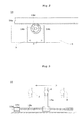
- Fig. 2 is a schematic view showing an outline of an FPD drive mechanism relating to driving of a flat panel X-ray detector.
- Fig. 3 is a schematic view showing an outline of an X-ray tube driver relating to driving of an X-ray tube.
- FPD flat panel X-ray detector
- X-ray body section imaging apparatus as an example of radiographic apparatus.
- the X-ray body section imaging apparatus includes a top board 1 for supporting a patient M, an X-ray tube 2 for emitting X rays toward the patient M, and an FPD 3 for detecting X rays transmitted through the patient M.
- the X-ray tube 2 corresponds to the radiation emitting device in this invention.
- the FPD 3 corresponds to the radiation detecting device in this invention.
- the X-ray body section imaging apparatus further includes a top board controller 4 for controlling vertical and horizontal movements of the top board 1, an FPD controller 5 for controlling scanning action of the FPD 3, an X-ray tube controller 7 having a high voltage generator 6 for generating a tube voltage and tube current for the X-ray tube 2, an analog-to-digital converter 8 for digitizing and fetching X-ray detection signals which are charge signals from the FPD 3, an image processor 9 for performing various processes based on the X-ray detection signals outputted from the analog-to-digital converter 8, a controller 10 for performing an overall control of these components, a memory 11 for storing processed images, an input unit 12 for the operator to input various settings, and a monitor 13 for displaying the processed images and other information.
- the monitor 13 corresponds to the output device in this invention.
- the top board controller 4 controls movement of the top board 1, such as moving the top board 1 horizontally to place the patient M in an imaging position, vertically moving and/or rotating the top board 1 to set the patient M to a desired position, horizontally moving the top board 1 during an imaging operation, and horizontally moving the top board 1 to withdraw the patient M from the imaging position after the imaging operation.
- These controls are carried out by controlling a top board driving mechanism (not shown) including motors and encoders (not shown).
- the FPD controller 5 controls the FPD 3 to make parallel translation along the direction of a body axis z which is a longitudinal direction of the patient M. As shown in Fig. 2 , this control is carried out by controlling an FPD drive mechanism 14 including a rack 14a, a pinion 14b, a motor 14c and an encoder 14d. Specifically, the rack 14a extends along the direction of body axis z of the patient M. The pinion 14b supports the FPD 3, is in part meshed with the rack 14a, and is rotatable by rotation of the motor 14c. For example, when the motor 14c is rotated forward, the FPD 3 will make parallel translation along the rack 14a toward the feet of the patient M as shown in the alternate long and short dash line in Fig.
- the encoder 14d detects a direction of rotation and an amount of rotation of the motor 14c corresponding to a direction of movement and an amount of movement (moving distance) of the FPD 3. Results of detection by the encoder 14d are sent to the FPD controller 5.
- the high voltage generator 6 generates the tube voltage and tube current for application to the X-ray tube 2 to emit X rays.
- the X-ray tube controller 7 controls the X-ray tube 2 to make parallel translation along the direction of body axis z of the patient M. As shown in Fig. 3 , this control is carried out by controlling an X-ray tube driver 15 including a strut 15a, a threaded rod 15b, a motor 15c and an encoder 15d.
- the strut 15a carries and supports the X-ray tube 2 on an upper end portion thereof, and is screwed to the threaded rod 15b at a lower end portion.
- the threaded rod 15b extends along the direction of body axis z of the patient M and is rotatable by rotation of the motor 15c.
- the motor 15c when the motor 15c is rotated forward, the X-ray tube 2 will make parallel translation with the strut 15a toward the feet of the patient M as shown in the alternate long and short dash line in Fig. 3 .
- the motor 15c When the motor 15c is reversed, the X-ray tube 2 will make parallel translation with the strut 15a toward the head of the patient M as shown in the two-dot chain line in Fig. 3 .
- the encoder 15d detects a direction of rotation and an amount of rotation of the motor 15c corresponding to a direction of movement and an amount of movement (moving distance) of the X-ray tube 2. Results of detection by the encoder 15d are sent to the X-ray tube controller 7.
- the FPD controller 5 and X-ray tube controller 7 carry out controls so that the direction of rotation of the motor 14c in Fig. 2 and the direction of rotation of the motor 15c in Fig. 3 may be the same.
- the X-ray tube controller 7 controls also setting of an irradiation field of a collimator (not shown) adjacent the X-ray tube 2.
- an irradiation field is set by controlling the collimator to emit X rays in a fan beam form diverging in the longitudinal direction (the direction of body axis z) and the transverse direction (direction perpendicular in a horizontal plane to the body axis z) of the patient M.
- the X-ray tube controller 7 controls the X-ray tube 2 to emit X rays (in the fan beam form) intermittently whenever the X-ray tube 2 and FPD 3 move every pitch (predetermined distance) described hereinafter.
- the FPD controller 5 controls the FPD 3 to detect X rays transmitted through the patient M irradiated intermittently.
- the controller 10 has a central processing unit (CPU) and other elements.
- the memory 11 has storage media, typically a ROM (Read-Only Memory) and RAM (Random Access Memory).
- the input unit 12 has a pointing device, typically a mouse, keyboard, joy stick, trackball and/or touch panel.
- the image processor 9 includes a correcting unit 9a for carrying out lag correction and gain correction on the X-ray detection signals and outputting X-ray images projected on the detecting plane of FPD 3, an image decomposing unit 9b for decomposing the corrected X-ray images for every pitch, an image composing unit 9c for composing the decomposed images for each projection angle to obtain a projection image for each projection angle, and a reconstruction processing unit 9d for carrying out a reconstruction process based on the composed projection images to obtain a sectional image.
- the image decomposing unit 9b corresponds to the image decomposing device in this invention.
- the image composing unit 9c corresponds to the image composing device in this invention.
- the reconstruction processing unit 9d corresponds to the reconstruction processing device in this invention. Specific functions of the image decomposing unit 9b, image composing unit 9c and reconstruction processing unit 9d will be described hereinafter with reference to Figs. 6-8 .
- the memory 11 is constructed for writing and storing each image processed by the image processor 9. As does the controller 10, the FPD controller 5 and X-ray tube controller 7 also have CPUs and so on.
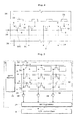
- Fig. 4 is an equivalent circuit, seen in side view, of the flat panel X-ray detector (FPD).
- Fig. 5 is an equivalent circuit, seen in plan view, of the flat panel X-ray detector (FPD).
- the FPD 3 includes a glass substrate 31, and thin film transistors TFT formed on the glass substrate 31.
- the thin film transistors TFT comprise numerous (e.g. 1,024 ⁇ 1,024) switching elements 32 arranged in a two-dimensional matrix of rows and columns. The switching elements 32 are formed separate from one another for respective carrier collecting electrodes 33.
- the FPD 3 is also a two-dimensional array radiation detector.
- an X-ray sensitive semiconductor 34 is laminated on the carrier collecting electrodes 33.
- the carrier collecting electrodes 33 are connected to the sources S of the switching elements 32.
- a plurality of gate bus lines 36 extend from a gate driver 35, and are connected to the gates G of the switching elements 32.
- a plurality of data bus lines 39 are connected through amplifiers 38 to a multiplexer 37 for collecting charge signals and outputting as one.
- each data bus line 39 is connected to the drains D of the switching elements 32.
- the gates of the switching elements 32 are turned on by applying thereto (or reducing to 0V) the voltage of the gate bus lines 36.
- the carrier collecting electrodes 33 output charge signals (carriers) converted from X rays incident on the detecting plane through the X-ray sensitive semiconductor 34, to the data bus lines 39 through the sources S and drains D of the switching elements 32.
- the charge signals are provisionally stored in capacitors (not shown) until the switching elements are turned on.
- the amplifiers 38 amplify the charge signals read out to the data bus lines 39, and the multiplexer 37 collects the charge signals, and outputs them as one charge signal.
- the analog-to-digital converter 8 digitizes the outputted charge signals, and outputs them as X-ray detection signals.
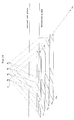
- Fig. 6 is a schematic view depicting for every pitch (predetermined distance) an image pickup principle by the X-ray tube and flat panel X-ray detector (FPD).
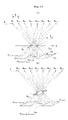
- Figs. 7 and 8 are schematic views depicting separation of images and composition for projection images. Description will be made assuming that X-ray images projected on the detecting plane of FPD 3 have already gone through the processes of lag correction and gain correction by the correcting unit 9a.
- X-ray images projected on the detecting plane of FPD 3, as the X-ray tube 2 and FPD 3 move every pitch d as shown in Figs. 6(a)-6(d) are referred to as O 1 , O 2 , ..., O I , ..., and O H M as shown in Figs. 6(e)-6(h) (1 ⁇ I ⁇ M).
- the X-ray tube 2 and FPD 3 move every pitch d
- the X-ray tube 2 emits X rays intermittently. That is, with movement by every pitch d, X rays are emitted in pulse.
- X rays are first emitted with the X-ray tube 2 and FPD 3 located in the position shown in Fig. 6(a)
- X rays are next emitted in the position shown in Fig. 6(b) after movement by pitch d.
- the FPD 3 detects the X rays in Fig. 6(a) , to obtain X-ray image O 1 (see Fig. 6(e) ).
- the FPD 3 detects X rays in Fig. 6(b) , to obtain X-ray image O 2 (see Fig. 6(f) ).
- FIG. 6(a) is the head of the patient M
- the image pickup end position in Fig. 6(d) is the feet of the patient M
- movement is made in order from the head to the feet with the movement of the X-ray tube 2 and FPD 3 as in Figs. 6(a)-6(d) .
- the image decomposing unit 9b can decomposes X-ray images O 1 , O 2 , ..., O I , ..., and O M at every pitch d.
- projection angles which are angles between the radiation axis from the X-ray tube 2 to the FPD 3 and the body axis z of the patient are referred to as ⁇ 1 , ⁇ 2 , ..., ⁇ J , ..., ⁇ N-1 and ⁇ N for every pitch d (1 ⁇ J ⁇ N).
- the images decomposed at every pitch d coincide with images divided into the same projection angles ⁇ 1 , ⁇ 2 , ..., ⁇ J , ..., ⁇ N-1 and ⁇ N , respectively.
- X-ray image O 1 is decomposed at every pitch d into O 11 , O 12 , ..., O 1J , ..., O 1(N-1) and O 1N .
- Decomposed image O 11 is an image obtained from an emission at projection angle ⁇ 1 .
- Decomposed image O 12 is an image obtained from an emission at projection angle ⁇ 2 .
- decomposed image O 1J is an image obtained from an emission at projection angle ⁇ J .
- decomposed image O 1N is an image obtained from an emission at projection angle ⁇ N .
- X-ray image O 2 is decomposed at every pitch d into O 21 , O 22 , .., O 2J , ..., O 2(N-1) and O 2N .
- Decomposed image O 21 is an image obtained from the emission at projection angle ⁇ 1 .
- Decomposed image O 22 is an image obtained from the emission at projection angle ⁇ 2 .
- decomposed image O 2J is an image obtained from the emission at projection angle ⁇ J .
- decomposed image O 2N is an image obtained from the emission at projection angle ⁇ N .
- X-ray image O I is decomposed at every pitch d into O I1 , O I2 , ..., O IJ , ..., O I(N-1) and O IN .
- Decomposed image O I1 is an image obtained from the emission at projection angle ⁇ 1 .
- Decomposed image O I2 is an image obtained from the emission at projection angle ⁇ 2 .
- decomposed image O IJ is an image obtained from the emission at projection angle ⁇ J .
- decomposed image O IN is an image obtained from the emission at projection angle ⁇ N .
- X-ray image O I is decomposed at every pitch d into O M1 , O M2 , ..., O MJ , ..., O M(N-1) and O MN .
- Decomposed image O M1 is an image obtained from the emission at projection angle ⁇ 1 .
- Decomposed image O M2 is an image obtained from the emission at projection angle ⁇ 2 .
- decomposed image O MJ is an image obtained from the emission at projection angle ⁇ J .
- decomposed image O MN is an image obtained from the emission at projection angle ⁇ N .
- the image composing unit 9c composes the images decomposed in this way, for each of the same projection angles ⁇ 1 , ⁇ 2 , ..., ⁇ J , ..., ⁇ N-1 and ⁇ N as shown in Figs. 7 and 8 .
- the respective X-ray images O 1 , O 2 , ..., O I , ..., and O M have decomposed images (that is, divided into the projection angles ⁇ 1 , ⁇ 2 , ..., ⁇ J , ..., O N-1 and ⁇ N ) for each pit d as shown in Figs. 7(a)-7(d), Figs. 7(f)-7(i) , Figs. 8(a)-8(d), and Figs. 8(f)-8(i) .
- image O 11 in X-ray image O 1 shown in Fig. 7(a) , image O 21 in X-ray image O 2 shown in Fig. 7(b) , ..., image O I1 in X-ray image O I shown in Fig. 7(c) , ..., and image O M1 in X-ray image O M shown in Fig. 7(d) are composed to obtain projection image P 1 for projection angle ⁇ 1 as shown in Fig. 7(e) .
- image O 12 in X-ray image O 1 shown in Fig. 7(f) image O 22 in X-ray image O 2 shown in Fig. 7(g) , ..., image O I2 in X-ray image O I shown in Fig. 7(h) , ..., and image O M2 in X-ray image O M shown in Fig. 7(i) are composed to obtain projection image P 2 for projection angle ⁇ 2 as shown in Fig. 7(j).
- image O 1J in X-ray image O 1 shown in Fig. 8(a) image O 2J in X-ray image O 2 shown in Fig. 8(b) , ..., image O IJ in X-ray image O I shown in Fig. 8(c) , ..., and image O MJ in X-ray image O M shown in Fig. 8(d) are composed to obtain projection image P J for projection angle ⁇ J as shown in Fig. 8(e) .
- image O IN in X-ray image O 1 shown in Fig. 8(f) image O 2N in X-ray image O 2 shown in Fig. 8(g) , ..., image O IN in X-ray image O I shown in Fig. 8(h) , ..., and image O MN in X-ray image O M shown in Fig. 8(i) are composed to obtain projection image P N for projection angle ⁇ N as shown in Fig. 8(j).
- the image composing unit 9c composes the decomposed images for each of the same projection angles ⁇ 1 , ⁇ 2 , ..., ⁇ J , ..., ⁇ N-1 and ⁇ N to obtain projection images P 1 , P 2 , ..., P J , ..., and P N for the respective projection angles ⁇ 1 , ⁇ 2 , ..., ⁇ J , ..., ⁇ N-1 and ⁇ N as shown in Figs. 7(e) , 7(j), 8(e) and 8(j).
- the reconstruction processing unit 9d carries out a reconstruction process based on the composed projection images Pi, P 2 , ..., P J , ..., and P N to obtain a sectional image.
- the reconstruction process may be carried out with the Feldkamp method using the well-known filtered back projection (FBP) (also called “filter-corrected back projection").
- FBP filtered back projection
- the Feldkamp method will be described hereinafter with reference to Figs. 9-19 .
- the number N of projection images P 1 , P 2 , ..., P J , ..., and P N is 50 [Frames]
- the image pickup speed F is 15 [Frames/sec]
- the X-ray tube 2 and FPD 3 are moved parallel to each other at the same speed of 129 [mm/sec], and X rays are emitted intermittently with the timing of image pickup speed 15 [Frame/sec], whereby X rays are emitted intermittently from the X-ray tube 2 as the X-ray tube 2 and FPD 3 move every pitch 8.6 [mm/Frame].
- 50 projection images P 1 , P 2 , ..., P J , ..., and P 50 can be obtained.
- the longer distance the X-ray tube 2 and FPD 3 move the longer becomes the area of each of the projection images P 1 , P 2 , ..., P J , ..., and P N as shown in Figs. 7 and 8 .
- Fig. 9(a) is a schematic view of arcuate track body section radiography.
- Fig. 9(b) is a schematic view of linear track body section radiography.
- Fig. 10 is a schematic view illustrating the Feldkamp algorithm according to the embodiment.
- Fig. 11 is a characteristic view of a filter function.
- Fig. 12 is a block diagram of the reconstruction processing unit according to the embodiment and a schematic view showing a flow of data.
- Fig. 13 is a schematic view illustrating a method of applying Feldkamp to linear track body section radiography.
- FIG. 14-16 are schematic views showing a relationship between an image of a common projection angle of each X-ray emission and a projection image for illustrating a method of applying Feldkamp to long X-ray images.
- Fig. 18 is a schematic view showing a relationship between cut plane and projection image for illustrating a method of applying Feldkamp to long X-ray images.
- Fig. 19 is a schematic view showing a relationship between cut plane and projection image for illustrating a method of applying Feldkamp to long X-rays images. While the body axis was z in Fig. 20 and Figs. 1-8 , Figs. 9-19 will be described with the body axis as y because of the representation of 3D coordinates in the Feldkamp method.
- the Feldkamp method is used for the sectional image reconstruction method used in cone beam CT. Although this is applied to the arcuate track body section radiography shown in Fig. 9(a) , it is extensible also to the linear track body section radiography shown in Fig. 9(b) . First of all, a reconstruction method of the arcuate track body section by the Feldkamp method will be described. The extension to the linear track body section will be described next.
- Coordinates x, y and z are a coordinate system fixed to space.
- the imaging system including the X-ray tube 2 and FPD 3 rotates about the axis of this z-axis. That is, the X-ray tube 2 makes a circular motion with radius D about the origin on x-y plane.
- g y is a filter for reducing obstructive shadows (flow images) occurring in Y-direction at a time of reconstructing a sectional image, and an example thereof is shown in Fig. 11 .
- the projection angle was ⁇ in Figs. 1-8
- Figs. 9-19 will be described with the projection angle as ⁇ because of the representation of the algorithm in the Feldkamp method.
- projection angle ⁇ ⁇ .
- W 1 D/(D 2 +Y' 2 +Z 2 ) 1/2
- Fig. 12 shows a block diagram of components of the reconstruction processing unit 9d (see Fig. 1 also) for carrying out the above processes, and a How of data. Specifically, a first weighting processing unit 9A weights the projection data with W 1 , a convolution processing unit 9B carries out convolution (convolution integral) thereof by filter function g y , a second weighting processing unit 9C weights it with W 2 , and a back projection processing unit 9D carries out back projection thereof to acquire a reconstruction image (i.e. sectional images).
- a first weighting processing unit 9A weights the projection data with W 1
- a convolution processing unit 9B carries out convolution (convolution integral) thereof by filter function g y
- a second weighting processing unit 9C weights it with W 2
- a back projection processing unit 9D carries out back projection thereof to acquire a reconstruction image (i.e. sectional images).
- a perpendicular extending down from the X-ray tube 2 during rotation is at right angles to the detecting plane of FPD 3 as shown in Fig. 9(a) .
- the center of the cone beam-like X-ray beam emitted from the X-ray tube 2 passes through the center C of a certain sectional plane, and does not always impinge at right angles on the center of the detecting plane of FPD 3. That is, the angle of incidence on the central point of the detecting plane of FPD 3 is a different angle for each view, and therefore the Feldkamp method cannot directly be applied in this state.
- an imaginary rotation center axis VAC refers to an axis that extends perpendicular to a straight line along which the center of the X-ray beam strikes at right angles the central point on the detecting plane of FPD 3, extends perpendicular to the moving direction or the X-ray tube 2 and FPD 3, and passes through a sectional plane substantially centrally of an area of interest of the patient M.
- a first perpendicular from the X-ray tube 2 to the central point of the detecting plane of FPD 3 is assumed to have a length SID.
- SHOD a distance along this from the X-ray tube 2 to the center C of a particular sectional plane.
- rc y r y + SOD ⁇ tan ⁇
- rc y is a length from VC to vrc, which is the length of r vector (SOD ⁇ tan ⁇ is written as "D*tan ⁇ " in Fig. 13 ).
- the reconstruction process may be carried out about each pixel only by changing parameter Y(r) in the above equation (1) based on the above equation (6) (that is, carrying out a coordinate correction).
- the Feldkamp method can be applied without modifying the data of the source image. The description has been made so far with reference to "japanese Patent No. 3926574 ".
- Figs. 14-16 show a positional relationship in which images with fixed projection angles of X-ray emission appear as X-ray images O 1 , O 2 , ..., O I , ..., and O M (also see Figs. 6-8 ).
- a moving distance of the X-ray tube 2 and FPD 3 for every X-ray emission is L
- L for each X-ray emission (X-ray irradiation) images in the shape of strips with width L in the central cut plane (plane parallel to the body axis y and parallel in a horizontal plane in Fig.
- Fig. 17 shows a relationship with projection images of one section of the central cut plane.
- N in Fig. 17 is the integral part of the length of FPD 3 divided by image O IJ (i.e. length of FPD 3 / image O IJ ), which shows how many O IJ can be acquired with one detecting plane.
- a relationship between the cut surface and projection image O IJ is shown in Fig. 18 .
- the projection image group of Ti is the following images indicated by the arrows in the figure. This may be depicted as in Fig. 19.
- Fig. 19 shows the Kth and (K+1)th cut planes T K and T K+1 .
- O IJ is the Jth strip image of the Ith projection image, i.e. the decomposed image at the time of projection angle ⁇ N (projection angle ⁇ N in Figs. 9-19 ) obtained from the Ith pitch movement.
- Width L is pitch d noted hereinbefore (see Fig. 6 ).
- Information around the patient plane T K is reconstructed by O KI , O (K-1)2 , O (K-2)3 , ... O( K-(N-1)) N as shown in Fig. 19(a) .
- the Feldkamp method noted hereinbefore is applied to this reconstruction.
- information around the hollowing patient plane T K+1 is reconstructed by O (K+1)I , O K2 , O (K-1)3 , ... O( K+1-(N-1)) N as shown in Fig. 19(b) .
- the Feldkamp method is similarly applied to the reconstruction.
- each strip portion T I is separated by distance L x (T-1). Therefore, each image is shifted in y-direction by L x (I-1) x SID/SOD.
- L x (I-1) x SID/SOD.
- reconstructed images of the peripheries of each strip portion Ti may be obtained and processes may be carried out to join (compose) them.
- a reconstructed image fi(r) around T I is expressed by the following equation (7) applied from the foregoing equation (1).
- Numeric 2 fi r / 4 ⁇ ⁇ 2 1 ⁇ W 2 ⁇ ⁇ g y ⁇ O I - ⁇ - 1 ⁇ ⁇ ⁇ W 1 ⁇ dY ⁇ d ⁇
- this can reconstruct each fragment (section) in the longitudinal direction (that is, the direction of the body axis which is the longitudinal direction of the patient M) by the Feldkamp method, and it can be said that a composition (combination) of the reconstruction results is equivalent to a reconstruction by the Feldkamp method using long images as the projection images. That is, the same effect is acquired even when reconstruction is carried out after obtaining long images.
- data of a long field of view of the body axis z which is the longitudinal direction can be obtained from the FPD 3 bye constructing that the X-ray tube 2 and flat panel X-ray detector (FPD) 3 are movable parallel to each other in the same direction along the body axis z which is the longitudinal direction of the patient M.
- FPD flat panel X-ray detector
- the image decomposing unit 9b decomposes the X-ray images for every pitch noted above.
- the image composing unit 9c composes the decomposed images for each of the same projection angles to obtain projection images for each projection angle. Therefore, the reconstruction processing unit 9d can obtain a sectional image having a long field of view in the longitudinal direction by carrying out a reconstruction process based on the composed projection images.
- the X-ray tube 2 and FPD 3 move parallel to each other at the same speed. With the X-ray tube 2 and FPD 3 moving parallel to each other at the same speed, the projection angle can be maintained at the same angle. The X-ray tube 2 and FPD 3 can be moved for a long time. As a result, a sectional image with a longer field of view can be obtained.
- leg bolus chasing is a technique of scanning a leg for every cut plane. By applying images in cut planes to the projection images noted hereinbefore (see Figs. 7 and 8 ), leg bolus chasing can be carried out easily.
- This embodiment provides the monitor 13 for displaying and outputting the sectional images obtained by the reconstruction processing unit 9d.
- monitor 13 it is possible to browse displays.
- a printing device represented by a printer may be provided.
- the printing device corresponds to the output device in this invention. With the printing device outputting prints, it is possible to browse the prints.
- Both the monitor 13 and a printer may be provided.
Landscapes
- Health & Medical Sciences (AREA)
- Life Sciences & Earth Sciences (AREA)
- Engineering & Computer Science (AREA)
- Medical Informatics (AREA)
- Physics & Mathematics (AREA)
- Biomedical Technology (AREA)
- Animal Behavior & Ethology (AREA)
- Biophysics (AREA)
- Nuclear Medicine, Radiotherapy & Molecular Imaging (AREA)
- Optics & Photonics (AREA)
- Pathology (AREA)
- Radiology & Medical Imaging (AREA)
- Veterinary Medicine (AREA)
- Heart & Thoracic Surgery (AREA)
- Molecular Biology (AREA)
- Surgery (AREA)
- High Energy & Nuclear Physics (AREA)
- General Health & Medical Sciences (AREA)
- Public Health (AREA)
- Computer Vision & Pattern Recognition (AREA)
- Mathematical Physics (AREA)
- Pulmonology (AREA)
- Theoretical Computer Science (AREA)
- Apparatus For Radiation Diagnosis (AREA)
- Transforming Light Signals Into Electric Signals (AREA)
- Analysing Materials By The Use Of Radiation (AREA)
Abstract
Description
- This invention relates to a radiographic apparatus for carrying out a radiation image pickup by obtaining radiographic images based on radiation detected, and more particularly to a technique for obtaining sectional images through a reconstruction process.
- Radiographic apparatus which obtain sectional images through a reconstruction process include an X-ray CT (computed tomography) apparatus and an X-ray body section imaging apparatus. In the X-ray CT apparatus, sectional images are obtained by an X-ray tube (radiation emitting device) and an X-ray detector (radiation detecting device) rotating about the body axis extending longitudinally of a patient. In the X-ray body section imaging apparatus, as shown in
Fig. 20 , for example, sectional images are obtained by anX-ray tube 101 and anX-ray detector 102 making parallel translation in opposite directions along the body axis z of a patient M. In the case of the X-ray body section imaging apparatus, compared with the X-ray CT apparatus, the resolution of sectional images obtained is inferior, but there is an advantage that sectional images can be obtained through parallel translation. The image pickup mode adopted in such X-ray CT apparatus and X-ray body section imaging apparatus is an image pickup method effective for many sites such as the chest, joints and digestive organs. - On the other hand, there has been an X-ray apparatus in recent years which obtains X-ray images along the body axis of a patient by moving an X-ray tube and an X-tray detector in parallel to each other in the same direction along the body axis of the patient (see
Patent Document 1, for example). The X-ray images obtained with this apparatus are projection data of projected X rays (projection images). Since the X-ray tube and X-ray detector move parallel to each other in the same direction along the body axis, the projection angle can be maintained at substantially the same angle. Therefore, X-ray images can be obtained of a long area (long X-ray images) in the longitudinal direction which is the direction of the body axis. - [Patent Document 1]
- Unexamined Patent Publication No.
2004-236929 (pages 1-8,Figs. 1 ,6 and10 ) - However, the above X-ray body section imagine apparatus has a limited field of view. An image intensifier (I. I) or the like was used as the X-ray detector in the past, but in recent years a flat panel X-ray detector (hereinafter abbreviated as "FPD") has been used as shown in
Fig. 20 . The FPD, with the detecting plane being a flat plane, has a larger field of view than the image intensifier. However, with the X-ray body section imaging apparatus, the farther from the area of interest, the lower becomes the resolution noted above. Since theX-ray tube 101 andX-ray detector 102 move parallel to each other in opposite directions, resolution will fall as the angle formed between the radiation axis connecting theX-ray detector 102 andX-ray tube 101 and the body axis z of the patient (hereinafter called the "projection angle") deviates from the vertical to become an acute angle or obtuse angle. As a result, the field of view is limited even when the FPD is used as the X-ray detector. Thus, tomography with a field of view long in the direction of the body axis is desired. - This invention has been made having regard to the state of the art noted above, and its object is to provide a radiographic apparatus which can obtain sectional images with a long field of view.
- To solve the above problem, Inventor has made intensive research and attained the following findings.
- That is, attention has been directed to the X-tray apparatus which obtains a long X-ray image in the longitudinal direction as in
Patent Document 1 noted above. Then, a long X-ray image can be obtained in the longitudinal direction if a construction is made as in this X-ray apparatus in which a radiation emitting device represented by the X-ray tube and a radiation detecting device represented by the X-ray detector move parallel to each other in the same direction along a longitudinal direction which is the direction of the body axis or a patient. On the other hand, since the long X-ray image obtained inPatent Document 1 is a projection image, a further image pickup mode and a construction for obtaining sectional images are needed. - Then, as the former, further image pickup mode, radiation is intermittently emitted from the radiation emitting device whenever the radiation emitting device and radiation detecting device move every predetermined distance, and the radiation detecting device detects radiation transmitted through the patient irradiated intermittently. As the latter construction for obtaining sectional images, radiographic images are decomposed for every predetermined distance noted above, and the decomposed images are composed for every projection angle to obtain a projection image for every projection angle. It has been found that a sectional image with a long field of view in the longitudinal direction can be obtained through a reconstruction process based on the composed projection images.
- Based on the above findings, this invention provides the following construction.
- A radiographic apparatus according to this invention is a radiographic apparatus having a radiation emitting device for emitting radiation toward a patient, and a radiation detecting device for detecting radiation transmitted through the patient, to carry out radiation image pickup by obtaining radiographic images based on the detected radiation, the radiation emitting device and the radiation detecting device being constructed movable parallel relative to each other in the same direction along a longitudinal direction of the patient, the radiation emitting device intermittently emitting radiation and the radiation detecting device detecting radiation transmitted through the patient irradiated intermittently whenever the radiation emitting device and the radiation detecting device move every predetermined distance relative to the patient, said apparatus comprising an image decomposing device for decomposing the radiographic image for the every predetermined distance, an image composing device for composing the decomposed images for each of the same projection angles to obtain a projection image for each projection angle, and a reconstruction processing device for carrying out a reconstruction process based on the composed projection images to obtain a sectional images.
- According to the radiographic apparatus of this invention, data with a long field of view in the longitudinal direction can be obtained from the radiation detecting device, by constructing the radiation emitting device and the radiation detecting device to be movable parallel relative to each other in the same direction along the longitudinal direction of the patient. On the other hand, the radiation emitting device intermittently emits radiation and the radiation detecting device detects radiation transmitted through the patient irradiated intermittently whenever the radiation emitting device and the radiation detecting device move every predetermined distance relative to the patient. And the image decomposing device decomposes the radiographic image for the every predetermined distance, and the image composing device composes the decomposed images for each of the same projection angles to obtain a projection image for each projection angle. Thus, the reconstruction processing device carries out a reconstruction process based on the composed projection images, thereby to obtain a sectional image with a long field of view in the longitudinal direction.
- In the invention noted above, preferably, the radiation emitting device and the radiation detecting device are movable parallel relative to each other at an equal speed relative to the patient. With the radiation emitting device and the radiation detecting device movable parallel relative to each other at an equal speed relative to the patient, the projection angle can be maintained at the same angle, and the relative movement of the radiation emitting device and the radiation detecting device can be carried out longer. As a result, a sectional image with a longer field of view can be obtained.
- In one example of these inventions noted above, an output device is provided for outputting the sectional image obtained by the reconstruction processing device. With the output device provided, it is possible to browse outputs. The output device may be a display device represented by a monitor for outputting displays, or a printing device represented by a printer for outputting prints.
- With the radiographic apparatus according to this invention, the radiation emitting device and the radiation detecting device are constructed movable parallel relative to each other in the same direction along the longitudinal direction of the patient. The radiation emitting device is constructed to intermittently emit radiation and the radiation detecting device to detect radiation transmitted through the patient irradiated intermittently whenever the radiation emitting device and the radiation detecting device move every predetermined distance relative to the patient. The image decomposing device decomposes the radiographic image for the every predetermined distance, and the image composing device composes the decomposed images for each of the same projection angles to obtain a projection image for each projection angle. Thus, the reconstruction processing device carries out a reconstruction process based on the composed projection images, thereby to obtain a sectional image with a long field of view in the longitudinal direction.
-
-
Fig. 1 is a block diagram of an X-ray body section imaging apparatus according to an embodiment; -
Fig. 2 is a schematic view showing an outline of an FPD drive mechanism relating to driving of a flat panel X-ray detector (FPD); -
Fig. 3 is a schematic view showing an outline of an X-ray tube driver relating to driving of an X-ray tube; -
Fig. 4 is an equivalent circuit, seen in side view, of the flat panel X-ray detector (FPD); -
Fig. 5 is an equivalent circuit, seen in plan view, of the flat panel X-ray detector (FPD); -
Fig. 6(a)-(i) are schematic views depicting for each pitch (predetermined distance) an image pickup principle by the X-ray tube and flat panel X-ray detector (FPD); -
Fig. 7(a)-(j) are schematic views depicting separation of images and composition for projection images; -
Fig. 8(a)-(j) are schematic views depicting separation of images and composition for projection images; -
Fig. 9(a) is a schematic view of arcuate track body section radiography, and (b) is a schematic view of linear track body section radiography; -
Fig. 10 is a schematic view illustrating the Feldkamp algorithm according to the embodiment; -
Fig. 11 is a characteristic view of a filter function; -
Fig. 12 is a block diagram of a reconstruction processing unit according to the embodiment and a schematic view showing a flow of data; -
Fig. 13(a) and (b) are schematic views illustrating a method of applying Feldkamp to linear track body section radiography; -
Fig. 14 is a schematic view showing a relationship between an image of a common projection angle of each X-ray emission and a projection image for illustrating a method of applying Feldkamp to long X-ray images; -
Fig. 15 is a schematic view showing a relationship between an image of a common projection angle of each X-ray emission and a projection image for illustrating a method of applying Feldkamp to long X-ray images; -
Fig. 16 is a schematic view showing a relationship between an image of a common projection angle of each X-ray emission and a projection image for illustrating a method of applying Feldkamp to long X-ray images; -
Fig. 17 is a schematic view showing a relationship between each cut plane and projection image where N= 8 for illustrating a method of applying Feldkamp to long X-ray images; -
Fig. 18 is a schematic view showing a relationship between cut plane and projection image for illustrating a method of applying Feldkamp to long X-ray images; -
Fig. 19(a) and (b) are schematic views showing a relationship between cut plane and projection image for illustrating a method of applying Feldkamp to long X-ray images; and -
Fig. 20 is a side view showing an outline of a conventional X-ray body section imaging apparatus. -
- 2 ...
- X-ray tube
- 3 ...
- flat panel X-ray detector (FPD)
- 13 ...
- monitor
- 9b ...
- image decomposing unit
- 9c ...
- image composing unit
- 9d ...
- reconstruction processing unit
- d...
- pitch
- z ...
- body axis
- M ...
- patient
- An embodiment of this invention will be described hereinafter with reference to the drawings.
-
Fig. 1 is a block diagram of an X-ray body section imaging apparatus according to the embodiment.Fig. 2 is a schematic view showing an outline of an FPD drive mechanism relating to driving of a flat panel X-ray detector.Fig. 3 is a schematic view showing an outline of an X-ray tube driver relating to driving of an X-ray tube. This embodiment will be described, taking the flat panel X-ray detector (hereinafter abbreviated as "FPD") as an example of radiation detecting device, and the X-ray body section imaging apparatus as an example of radiographic apparatus. - As shown in
Fig. 1 , the X-ray body section imaging apparatus includes atop board 1 for supporting a patient M, anX-ray tube 2 for emitting X rays toward the patient M, and anFPD 3 for detecting X rays transmitted through the patient M. TheX-ray tube 2 corresponds to the radiation emitting device in this invention. TheFPD 3 corresponds to the radiation detecting device in this invention. - The X-ray body section imaging apparatus further includes a
top board controller 4 for controlling vertical and horizontal movements of thetop board 1, anFPD controller 5 for controlling scanning action of theFPD 3, anX-ray tube controller 7 having ahigh voltage generator 6 for generating a tube voltage and tube current for theX-ray tube 2, an analog-to-digital converter 8 for digitizing and fetching X-ray detection signals which are charge signals from theFPD 3, animage processor 9 for performing various processes based on the X-ray detection signals outputted from the analog-to-digital converter 8, acontroller 10 for performing an overall control of these components, amemory 11 for storing processed images, aninput unit 12 for the operator to input various settings, and amonitor 13 for displaying the processed images and other information. Themonitor 13 corresponds to the output device in this invention. - The
top board controller 4 controls movement of thetop board 1, such as moving thetop board 1 horizontally to place the patient M in an imaging position, vertically moving and/or rotating thetop board 1 to set the patient M to a desired position, horizontally moving thetop board 1 during an imaging operation, and horizontally moving thetop board 1 to withdraw the patient M from the imaging position after the imaging operation. These controls are carried out by controlling a top board driving mechanism (not shown) including motors and encoders (not shown). - The
FPD controller 5 controls theFPD 3 to make parallel translation along the direction of a body axis z which is a longitudinal direction of the patient M. As shown inFig. 2 , this control is carried out by controlling anFPD drive mechanism 14 including arack 14a, apinion 14b, amotor 14c and anencoder 14d. Specifically, therack 14a extends along the direction of body axis z of the patient M. Thepinion 14b supports theFPD 3, is in part meshed with therack 14a, and is rotatable by rotation of themotor 14c. For example, when themotor 14c is rotated forward, theFPD 3 will make parallel translation along therack 14a toward the feet of the patient M as shown in the alternate long and short dash line inFig. 2 . When themotor 14c is reversed, theFPD 3 will make parallel translation along therack 14a toward the head of the patient M as shown in the two-dot chain line inFig. 2 . Theencoder 14d detects a direction of rotation and an amount of rotation of themotor 14c corresponding to a direction of movement and an amount of movement (moving distance) of theFPD 3. Results of detection by theencoder 14d are sent to theFPD controller 5. - The
high voltage generator 6 generates the tube voltage and tube current for application to theX-ray tube 2 to emit X rays. TheX-ray tube controller 7 controls theX-ray tube 2 to make parallel translation along the direction of body axis z of the patient M. As shown inFig. 3 , this control is carried out by controlling anX-ray tube driver 15 including astrut 15a, a threadedrod 15b, amotor 15c and anencoder 15d. Specifically, thestrut 15a carries and supports theX-ray tube 2 on an upper end portion thereof, and is screwed to the threadedrod 15b at a lower end portion. The threadedrod 15b extends along the direction of body axis z of the patient M and is rotatable by rotation of themotor 15c. For example, when themotor 15c is rotated forward, theX-ray tube 2 will make parallel translation with thestrut 15a toward the feet of the patient M as shown in the alternate long and short dash line inFig. 3 . When themotor 15c is reversed, theX-ray tube 2 will make parallel translation with thestrut 15a toward the head of the patient M as shown in the two-dot chain line inFig. 3 . Theencoder 15d detects a direction of rotation and an amount of rotation of themotor 15c corresponding to a direction of movement and an amount of movement (moving distance) of theX-ray tube 2. Results of detection by theencoder 15d are sent to theX-ray tube controller 7. - In order that the
X-ray tube 2 andFPD 3 make parallel translation in the same direction along the direction of body axis z of the patient M as shown inFig. 1 , theFPD controller 5 andX-ray tube controller 7 carry out controls so that the direction of rotation of themotor 14c inFig. 2 and the direction of rotation of themotor 15c inFig. 3 may be the same. In this embodiment, it is preferred that theX-ray tube 2 andFPD 3 make parallel translation at an equal speed. That is, theFPD controller 5 controls the amount of rotation of themotor 14c and theX-ray tube controller 7 controls the amount of rotation of themotor 15c, so that the amount of movement of theX-ray tube 2 and the amount of movement of theFPD 3 may be the same. - The
X-ray tube controller 7 controls also setting of an irradiation field of a collimator (not shown) adjacent theX-ray tube 2. In this embodiment, an irradiation field is set by controlling the collimator to emit X rays in a fan beam form diverging in the longitudinal direction (the direction of body axis z) and the transverse direction (direction perpendicular in a horizontal plane to the body axis z) of the patient M. TheX-ray tube controller 7 controls theX-ray tube 2 to emit X rays (in the fan beam form) intermittently whenever theX-ray tube 2 andFPD 3 move every pitch (predetermined distance) described hereinafter. TheFPD controller 5 controls theFPD 3 to detect X rays transmitted through the patient M irradiated intermittently. - The
controller 10 has a central processing unit (CPU) and other elements. Thememory 11 has storage media, typically a ROM (Read-Only Memory) and RAM (Random Access Memory). Theinput unit 12 has a pointing device, typically a mouse, keyboard, joy stick, trackball and/or touch panel. - The
image processor 9 includes a correctingunit 9a for carrying out lag correction and gain correction on the X-ray detection signals and outputting X-ray images projected on the detecting plane ofFPD 3, animage decomposing unit 9b for decomposing the corrected X-ray images for every pitch, animage composing unit 9c for composing the decomposed images for each projection angle to obtain a projection image for each projection angle, and areconstruction processing unit 9d for carrying out a reconstruction process based on the composed projection images to obtain a sectional image. Theimage decomposing unit 9b corresponds to the image decomposing device in this invention. Theimage composing unit 9c corresponds to the image composing device in this invention. Thereconstruction processing unit 9d corresponds to the reconstruction processing device in this invention. Specific functions of theimage decomposing unit 9b,image composing unit 9c andreconstruction processing unit 9d will be described hereinafter with reference toFigs. 6-8 . - The
memory 11 is constructed for writing and storing each image processed by theimage processor 9. As does thecontroller 10, theFPD controller 5 andX-ray tube controller 7 also have CPUs and so on. - Next, the construction of the flat panel X-ray detector (FPD) 3 will be described with reference to
Figs. 4 and 5. Fig. 4 is an equivalent circuit, seen in side view, of the flat panel X-ray detector (FPD).Fig. 5 is an equivalent circuit, seen in plan view, of the flat panel X-ray detector (FPD). - As shown in
Fig. 4 , theFPD 3 includes aglass substrate 31, and thin film transistors TFT formed on theglass substrate 31. As shown inFigs. 4 and 5 , the thin film transistors TFT comprise numerous (e.g. 1,024×1,024) switchingelements 32 arranged in a two-dimensional matrix of rows and columns. The switchingelements 32 are formed separate from one another for respectivecarrier collecting electrodes 33. Thus, theFPD 3 is also a two-dimensional array radiation detector. - As shown in
Fig. 4 , an X-raysensitive semiconductor 34 is laminated on thecarrier collecting electrodes 33. As shown inFigs. 4 and 5 , thecarrier collecting electrodes 33 are connected to the sources S of the switchingelements 32. A plurality ofgate bus lines 36 extend from agate driver 35, and are connected to the gates G of the switchingelements 32. On the other hand, as shown inFig. 5 , a plurality ofdata bus lines 39 are connected throughamplifiers 38 to amultiplexer 37 for collecting charge signals and outputting as one. As shown inFigs. 4 and 5 , eachdata bus line 39 is connected to the drains D of the switchingelements 32. - With a bias voltage applied to a common electrode not shown, the gates of the switching
elements 32 are turned on by applying thereto (or reducing to 0V) the voltage of the gate bus lines 36. Thecarrier collecting electrodes 33 output charge signals (carriers) converted from X rays incident on the detecting plane through the X-raysensitive semiconductor 34, to thedata bus lines 39 through the sources S and drains D of the switchingelements 32. The charge signals are provisionally stored in capacitors (not shown) until the switching elements are turned on. Theamplifiers 38 amplify the charge signals read out to thedata bus lines 39, and themultiplexer 37 collects the charge signals, and outputs them as one charge signal. The analog-to-digital converter 8 digitizes the outputted charge signals, and outputs them as X-ray detection signals. - Next, specific functions of the
image decomposing unit 9b,image composing unit 9c andreconstruction processing unit 9d will be described with reference toFigs. 6-8 .Fig. 6 is a schematic view depicting for every pitch (predetermined distance) an image pickup principle by the X-ray tube and flat panel X-ray detector (FPD).Figs. 7 and8 are schematic views depicting separation of images and composition for projection images. Description will be made assuming that X-ray images projected on the detecting plane ofFPD 3 have already gone through the processes of lag correction and gain correction by the correctingunit 9a. - X-ray images projected on the detecting plane of
FPD 3, as theX-ray tube 2 andFPD 3 move every pitch d as shown inFigs. 6(a)-6(d) , are referred to as O1, O2, ..., OI, ..., and OHM as shown inFigs. 6(e)-6(h) (1≤ I ≤ M). Whenever theX-ray tube 2 andFPD 3 move every pitch d, theX-ray tube 2 emits X rays intermittently. That is, with movement by every pitch d, X rays are emitted in pulse. - Specifically, when X rays are first emitted with the
X-ray tube 2 andFPD 3 located in the position shown inFig. 6(a) , X rays are next emitted in the position shown inFig. 6(b) after movement by pitch d. TheFPD 3 detects the X rays inFig. 6(a) , to obtain X-ray image O1 (seeFig. 6(e) ). TheFPD 3 detects X rays inFig. 6(b) , to obtain X-ray image O2 (seeFig. 6(f) ). Similarly thereafter, as theX-ray tube 2 andFPD 3 move every pitch d, X rays are emitted for the (I-1)th time in the position shown inFig. 6(c) , and theFPD 3 detects the X rays inFig. 6(c) , to obtain X-ray image OI (seeFig. 6(g) ). Finally, X rays are emitted for the (M-1)th in the position shown inFig. 6(d) , and theFPD 3 detects the X rays inFig. 6(d) , to obtain X-ray image OM (seeFig. 6(h) ). In this embodiment, the image pickup start position inFig. 6(a) is the head of the patient M, the image pickup end position inFig. 6(d) is the feet of the patient M, and movement is made in order from the head to the feet with the movement of theX-ray tube 2 andFPD 3 as inFigs. 6(a)-6(d) . - With the
X-ray tube 2 andFPD 3 moving every pitch d, theimage decomposing unit 9b can decomposes X-ray images O1, O2, ..., OI, ..., and OM at every pitch d. Specifically, as shown in the enlarged view of Fig. 6(i), projection angles which are angles between the radiation axis from theX-ray tube 2 to theFPD 3 and the body axis z of the patient are referred to as θ1, θ2, ..., θJ, ..., θN-1 and θN for every pitch d (1 ≤ J ≤ N). Then, the images decomposed at every pitch d coincide with images divided into the same projection angles θ1, θ2, ..., θJ, ..., θN-1 and θN, respectively. - As shown in
Fig. 6(e) , X-ray image O1 is decomposed at every pitch d into O11, O12, ..., O1J, ..., O1(N-1) and O1N. Decomposed image O11 is an image obtained from an emission at projection angle θ1. Decomposed image O12 is an image obtained from an emission at projection angle θ2. Similarly thereafter, decomposed image O1J is an image obtained from an emission at projection angle θJ. Finally, decomposed image O1N is an image obtained from an emission at projection angle θN. - Similarly, as shown in
Fig. 6(f) , X-ray image O2 is decomposed at every pitch d into O21, O22, .., O2J, ..., O2(N-1) and O2N. Decomposed image O21 is an image obtained from the emission at projection angle θ1. Decomposed image O22 is an image obtained from the emission at projection angle θ2. Similarly thereafter, decomposed image O2J is an image obtained from the emission at projection angle θJ. Finally, decomposed image O2N is an image obtained from the emission at projection angle θN. - At the (I-1)th time, as shown in
Fig. 6(g) , X-ray image OI is decomposed at every pitch d into OI1, OI2, ..., OIJ, ..., OI(N-1) and OIN. Decomposed image OI1 is an image obtained from the emission at projection angle θ1. Decomposed image OI2 is an image obtained from the emission at projection angle θ2. Similarly thereafter, decomposed image OIJ is an image obtained from the emission at projection angle θJ. Finally, decomposed image OIN is an image obtained from the emission at projection angle θN. - Finally, at the (M-1)th time, as shown in
Fig. 6(h) , X-ray image OI is decomposed at every pitch d into OM1, OM2, ..., OMJ, ..., OM(N-1) and OMN. Decomposed image OM1 is an image obtained from the emission at projection angle θ1. Decomposed image OM2 is an image obtained from the emission at projection angle θ2. Similarly thereafter, decomposed image OMJ is an image obtained from the emission at projection angle θJ. Finally, decomposed image OMN is an image obtained from the emission at projection angle θN. - The
image composing unit 9c composes the images decomposed in this way, for each of the same projection angles θ1, θ2, ..., θJ, ..., θN-1 and θN as shown inFigs. 7 and8 . As described above, the respective X-ray images O1, O2, ..., OI, ..., and OM have decomposed images (that is, divided into the projection angles θ1, θ2, ..., θJ, ..., ON-1 and θN) for each pit d as shown inFigs. 7(a)-7(d), Figs. 7(f)-7(i) ,Figs. 8(a)-8(d), and Figs. 8(f)-8(i) . - In the case of projection angle θ1, for example, image O11 in X-ray image O1 shown in
Fig. 7(a) , image O21 in X-ray image O2 shown inFig. 7(b) , ..., image OI1 in X-ray image OI shown inFig. 7(c) , ..., and image OM1 in X-ray image OM shown inFig. 7(d) are composed to obtain projection image P1 for projection angle θ1 as shown inFig. 7(e) . - Similarly, in the case of projection angle θ2, image O12 in X-ray image O1 shown in
Fig. 7(f) , image O22 in X-ray image O2 shown inFig. 7(g) , ..., image OI2 in X-ray image OI shown inFig. 7(h) , ..., and image OM2 in X-ray image OM shown inFig. 7(i) are composed to obtain projection image P2 for projection angle θ2 as shown in Fig. 7(j). - At the (J-1)th time, in the case of projection angle θJ, image O1J in X-ray image O1 shown in
Fig. 8(a) , image O2J in X-ray image O2 shown inFig. 8(b) , ..., image OIJ in X-ray image OI shown inFig. 8(c) , ..., and image OMJ in X-ray image OM shown inFig. 8(d) are composed to obtain projection image PJ for projection angle θJ as shown inFig. 8(e) . - Finally, at the (N-1)th time, in the case of projection angle θN, image OIN in X-ray image O1 shown in
Fig. 8(f) , image O2N in X-ray image O2 shown inFig. 8(g) , ..., image OIN in X-ray image OI shown inFig. 8(h) , ..., and image OMN in X-ray image OM shown inFig. 8(i) are composed to obtain projection image PN for projection angle θN as shown in Fig. 8(j). - To summarize the above, the
image composing unit 9c composes the decomposed images for each of the same projection angles θ1, θ2, ..., θJ, ..., θN-1 and θN to obtain projection images P1, P2, ..., PJ, ..., and PN for the respective projection angles θ1, θ2, ..., θJ, ..., θN-1 and θN as shown inFigs. 7(e) , 7(j),8(e) and 8(j). - The
reconstruction processing unit 9d carries out a reconstruction process based on the composed projection images Pi, P2, ..., PJ, ..., and PN to obtain a sectional image. The reconstruction process may be carried out with the Feldkamp method using the well-known filtered back projection (FBP) (also called "filter-corrected back projection"). The Feldkamp method will be described hereinafter with reference toFigs. 9-19 . - Where the number of projection images P1, P2, ..., PJ, ..., and PN is N [Frames], the moving speed of the imaging system such as the
X-ray tube 2 andFPD 3 is v [mm/sec], the view size ofFPD 3 is V[mm], and the image pickup cycle (called "pulse time width") is T [sec/Frame], the moving speed v [mm/sec] is expressed by v[mm/sec] = V[mm]/N[Frame] × 1/T [sec/Frame]. The inverse of the image pickup cycle is image pickup speed, and where the image pickup speed is F [Frame/sec], the moving speed v [mm/sec] is expressed also by v[mm/sec] = V[mm]/N[Frame] × F [Frame/sec]. Pitch d [mm] is expressed by d [mm] = V[mm]/N [Frames]. - Where, for example, view size V used in this embodiment is 17 inches (= 430 [mml), the number N of projection images P1, P2, ..., PJ, ..., and PN, is 50 [Frames], and the image pickup speed F is 15 [Frames/sec], the moving speed v is v= [mm/sec] = 430[mm]/50[Frames] ×15 [Frames/sec] = 129 [mm/sec], and pitch d is 430[mm]/ 50[Frames] = 8.6 [mm/Frame]. Therefore, the
X-ray tube 2 andFPD 3 are moved parallel to each other at the same speed of 129 [mm/sec], and X rays are emitted intermittently with the timing of image pickup speed 15 [Frame/sec], whereby X rays are emitted intermittently from theX-ray tube 2 as theX-ray tube 2 andFPD 3 move every pitch 8.6 [mm/Frame]. And 50 projection images P1, P2, ..., PJ, ..., and P50 can be obtained. Further, the longer distance theX-ray tube 2 andFPD 3 move, the longer becomes the area of each of the projection images P1, P2, ..., PJ, ..., and PN as shown inFigs. 7 and8 . - Next, a specific technique in the case of applying this embodiment to the Feldkamp method will be described with reference to
Figs. 9-19 .Fig. 9(a) is a schematic view of arcuate track body section radiography.Fig. 9(b) is a schematic view of linear track body section radiography.Fig. 10 is a schematic view illustrating the Feldkamp algorithm according to the embodiment.Fig. 11 is a characteristic view of a filter function.Fig. 12 is a block diagram of the reconstruction processing unit according to the embodiment and a schematic view showing a flow of data.Fig. 13 is a schematic view illustrating a method of applying Feldkamp to linear track body section radiography.Figs. 14-16 are schematic views showing a relationship between an image of a common projection angle of each X-ray emission and a projection image for illustrating a method of applying Feldkamp to long X-ray images.Fig. 17 is a schematic view showing a relationship between each cut plane and projection image where N= 8 for illustrating a method of applying Feldkamp to long X-ray images.Fig. 18 is a schematic view showing a relationship between cut plane and projection image for illustrating a method of applying Feldkamp to long X-ray images.Fig. 19 is a schematic view showing a relationship between cut plane and projection image for illustrating a method of applying Feldkamp to long X-rays images. While the body axis was z inFig. 20 andFigs. 1-8 ,Figs. 9-19 will be described with the body axis as y because of the representation of 3D coordinates in the Feldkamp method. - The Feldkamp method is used for the sectional image reconstruction method used in cone beam CT. Although this is applied to the arcuate track body section radiography shown in
Fig. 9(a) , it is extensible also to the linear track body section radiography shown inFig. 9(b) . First of all, a reconstruction method of the arcuate track body section by the Feldkamp method will be described. The extension to the linear track body section will be described next. - The reconstruction algorithm by the Feldkamp method is expressed as the following equation (1) - equation (3). How to plot coordinates is shown in
Fig. 10 . Coordinates x, y and z are a coordinate system fixed to space. The imaging system including theX-ray tube 2 andFPD 3 rotates about the axis of this z-axis. That is, theX-ray tube 2 makes a circular motion with radius D about the origin on x-y plane.
- Here, gy is a filter for reducing obstructive shadows (flow images) occurring in Y-direction at a time of reconstructing a sectional image, and an example thereof is shown in
Fig. 11 . However, while the projection angle was θ inFigs. 1-8 ,Figs. 9-19 will be described with the projection angle as φ because of the representation of the algorithm in the Feldkamp method. InFig. 11 , projection angle φ = β. The term W1 (= D/(D2+Y'2+Z2)1/2) in equation (1) and equation (2) above is given for correction of changes in pixel values caused by the cone beam effect. - The integral equation of f(r), when point r in 3D coordinate space is fixed, adds pixel values of coordinates of this point reflected on the projection image at each angle φ. Paradoxically speaking, the projection image is back-projected to the 3D coordinate space, and is added to the 3D coordinate space. However, because of the cone beam effect, the pixel values need to be corrected by an amount corresponding to the term W2 (= D2/(D+r*x')2) in the above equation (1) and equation (3).
-
Fig. 12 shows a block diagram of components of thereconstruction processing unit 9d (seeFig. 1 also) for carrying out the above processes, and a How of data. Specifically, a firstweighting processing unit 9A weights the projection data with W1, aconvolution processing unit 9B carries out convolution (convolution integral) thereof by filter function gy, a secondweighting processing unit 9C weights it with W2, and a backprojection processing unit 9D carries out back projection thereof to acquire a reconstruction image (i.e. sectional images). - In the Feldkamp method which is a reconstruction technique of cone beam CT, a perpendicular extending down from the
X-ray tube 2 during rotation is at right angles to the detecting plane ofFPD 3 as shown inFig. 9(a) . However, in the linear track body section, as shown inFig. 9(b) andFig. 13(b) , the center of the cone beam-like X-ray beam emitted from theX-ray tube 2 passes through the center C of a certain sectional plane, and does not always impinge at right angles on the center of the detecting plane ofFPD 3. That is, the angle of incidence on the central point of the detecting plane ofFPD 3 is a different angle for each view, and therefore the Feldkamp method cannot directly be applied in this state. - Thus, as shown in
Fig. 13(b) , an imaginary rotation center axis VAC refers to an axis that extends perpendicular to a straight line along which the center of the X-ray beam strikes at right angles the central point on the detecting plane ofFPD 3, extends perpendicular to the moving direction or theX-ray tube 2 andFPD 3, and passes through a sectional plane substantially centrally of an area of interest of the patient M. A first perpendicular from theX-ray tube 2 to the central point of the detecting plane ofFPD 3 is assumed to have a length SID. And a distance along this from theX-ray tube 2 to the center C of a particular sectional plane is set to SHOD (= D). The length of a second perpendicular from the central point ofFED 3 in each view to the first perpendicular noted above is set to YA. Then, the length YA of the second perpendicular is expressed by the following equation (4):
- Therefore, when carrying out back projection of each view, Y(r) is changed according to YA = SID. tanφ (written "SID*tanφ" in
Fig. 13 ) each time to correspond to this imaginary rotation center axis VC. By carrying out the reconstruction process in this way, the Feldkamp method can be applied without working on the X-ray image which is the source image. - The above change of Y(r) will be described specifically. Regarding the imaginary rotation center axis VC as a reference in the space of the patient M, as to the same point of the patient M, the point indicated by vr (called "r vector") for B' in
Fig. 13(b) and the point indicated by vrc (called "re vector") for C" are considered the same point. Regarding the imaginary rotation center axis VC as a reference, the relationship in Y coordinates between the above two points is expressed as the following (5).
where rcy is a length from VC to vrc, which is the length of r vector (SOD·tanφ is written as "D*tanφ" inFig. 13 ). - And Y coordinates (based on VC) of the point where the X ray having passed vrc from the
X-ray tube 2 is projected on the detecting plane ofFPD 3 are set to Yc(r). Since theactual FPD 3 is considered to shift by YA = SID·tanφ, the coordinates on the detecting plane ofactual FPD 3 are expressed by the following equation (6):
where Yc(r) is expressed as Yc(r) = SID·rcy/SOD. - Thus, when carrying out back projection of each view, the reconstruction process may be carried out about each pixel only by changing parameter Y(r) in the above equation (1) based on the above equation (6) (that is, carrying out a coordinate correction). The Feldkamp method can be applied without modifying the data of the source image. The description has been made so far with reference to "japanese Patent No.
3926574 -
Figs. 14-16 show a positional relationship in which images with fixed projection angles of X-ray emission appear as X-ray images O1, O2, ..., OI, ..., and OM (also seeFigs. 6-8 ). Assuming that a moving distance of theX-ray tube 2 andFPD 3 for every X-ray emission is L, although theX-ray tube 2 andFPD 3 move the moving distance, L for each X-ray emission (X-ray irradiation), images in the shape of strips with width L in the central cut plane (plane parallel to the body axis y and parallel in a horizontal plane inFig. 19 ) are geometrically enlarged and projected with a width Ls = L x enlargement factor on the detecting plane of FPD 3 (see Ls and L inFig. 19 ). Subscript (suffix) M of OM inFigs. 14-16 indicates the number of radiograms (i.e. the number of times or X-ray emission). -
Fig. 17 shows a relationship with projection images of one section of the central cut plane. InFig. 17 , cut plane T8 of N = 8 (8th) is taken for example, to show that the images which project T8 are decomposed images O81, O72, O63, ..., and O18. N inFig. 17 is the integral part of the length ofFPD 3 divided by image OIJ (i.e. length ofFPD 3 / image OIJ), which shows how many OIJ can be acquired with one detecting plane. A relationship between the cut surface and projection image OIJ is shown inFig. 18 . The projection image group of Ti is the following images indicated by the arrows in the figure. This may be depicted as inFig. 19. Fig. 19 shows the Kth and (K+1)th cut planes TK and TK+1. - When the
X-ray tube 2 and FPD3 move the moving distance L for every X-ray emission, portions in the shape of strips of width L on a patient plane (i.e. cut plane on the patient M) T as noted hereinbefore are given as projection images of width Ls as shown inFig. 19 . As described with reference toFigs. 6-8 also, OIJ is the Jth strip image of the Ith projection image, i.e. the decomposed image at the time of projection angle θN (projection angle φN inFigs. 9-19 ) obtained from the Ith pitch movement. Width L is pitch d noted hereinbefore (seeFig. 6 ). - Information around the patient plane TK is reconstructed by OKI, O(K-1)2, O(K-2)3, ... O(K-(N-1)) N as shown in
Fig. 19(a) . The Feldkamp method noted hereinbefore is applied to this reconstruction. And information around the hollowing patient plane TK+1 is reconstructed by O(K+1)I, OK2, O(K-1)3, ... O(K+1-(N-1)) N as shown inFig. 19(b) . The Feldkamp method is similarly applied to the reconstruction. - From strip portion T1 at the extreme end (starting point) of the patient plane, each strip portion TI is separated by distance L x (T-1). Therefore, each image is shifted in y-direction by L x (I-1) x SID/SOD. In order to obtain reconstructed images (sectional images) of the entire patient M, reconstructed images of the peripheries of each strip portion Ti may be obtained and processes may be carried out to join (compose) them. A reconstructed image fi(r) around TI is expressed by the following equation (7) applied from the foregoing equation (1).

- An entire reconstructed image joining (composing) fi(r) is expressed by the following equation (8).

- With this equation, it is possible to change the order of the back projection and the combination of images according to φ. The change in the order of calculation results in the following equation (9).

- Here, ΣO(I-(φ-1)) φ in the above equation (9) (where Σ is a total of O(I-(φ-1)) φ with suffix I = N, ..., to M) is a combination of images with projection angle φ, i.e. an elongated image (long image) Pφ. Therefore, f(f) is finally expressed as in the following equation (10).

- In such long tomosynthesis, this can reconstruct each fragment (section) in the longitudinal direction (that is, the direction of the body axis which is the longitudinal direction of the patient M) by the Feldkamp method, and it can be said that a composition (combination) of the reconstruction results is equivalent to a reconstruction by the Feldkamp method using long images as the projection images. That is, the same effect is acquired even when reconstruction is carried out after obtaining long images.
- According to the X-ray body section imaging apparatus in this embodiment, data of a long field of view of the body axis z which is the longitudinal direction can be obtained from the
FPD 3 bye constructing that theX-ray tube 2 and flat panel X-ray detector (FPD) 3 are movable parallel to each other in the same direction along the body axis z which is the longitudinal direction of the patient M. On the other hand, whenever theX-ray tube 2 andFED 3 move every pitch (predetermined distance), X rays are intermittently emitted from theX-ray tube 2, and theFPD 3 detects X rays transmitted through the patient M intermittently irradiated. Wand theimage decomposing unit 9b decomposes the X-ray images for every pitch noted above. Theimage composing unit 9c composes the decomposed images for each of the same projection angles to obtain projection images for each projection angle. Therefore, thereconstruction processing unit 9d can obtain a sectional image having a long field of view in the longitudinal direction by carrying out a reconstruction process based on the composed projection images. - In this embodiment, the
X-ray tube 2 andFPD 3 move parallel to each other at the same speed. With theX-ray tube 2 andFPD 3 moving parallel to each other at the same speed, the projection angle can be maintained at the same angle. TheX-ray tube 2 andFPD 3 can be moved for a long time. As a result, a sectional image with a longer field of view can be obtained. - When the patient M is human as in this embodiment, a 3D grasp and diagnosis of pathological changes over large ranges can be carried out, producing also an effect of contributing to improved diagnostic performance. It provides also an effect of enabling a 3D grasp of scoliosis and a 3D grasp of leg bolus chasing. Here, the leg bolus chasing is a technique of scanning a leg for every cut plane. By applying images in cut planes to the projection images noted hereinbefore (see
Figs. 7 and8 ), leg bolus chasing can be carried out easily. - This embodiment provides the
monitor 13 for displaying and outputting the sectional images obtained by thereconstruction processing unit 9d. Withsuch monitor 13, it is possible to browse displays. Instead of being limited to the display device like themonitor 13, a printing device represented by a printer may be provided. In this case, the printing device corresponds to the output device in this invention. With the printing device outputting prints, it is possible to browse the prints. Both themonitor 13 and a printer may be provided. - This invention is not limited to the foregoing embodiment, but may be modified as follows:
- (1) In the foregoing embodiment, the X-ray body section imaging apparatus has been described as an example of radiographic apparatus. The invention may be applied to a radiographic apparatus, such as an ECT (Emission Computed Tomography) apparatus represented by a PET (Positron Emission Tomography) apparatus or a SPECT (Single Photon Emission CT) apparatus, which carries out radiation image pickup by detecting radiation other than X rays (gamma rays in the case of the PET apparatus) and obtaining radiographic images based on the detected radiation.
- (2) In the foregoing embodiment, the flat panel X-ray detector has been described as an example of radiation detecting device. There is no limitation as long as the device is an X-ray detecting device used generally, such as an image intensifier (I.I). As in the case of being applied to an ECT apparatus, as in modification (1) above, there is no limitation as long as it is a radiation detecting device used generally.
- (3) The foregoing embodiment provides the output device represented by the
monitor 13. The output device is not absolutely necessary. - (4) In the foregoing embodiment, the radiation emitting device represented by the
X-ray tube 2 and the radiation detecting device represented by theFPD 3 are moved parallel to each other at the same speed. As long as the radiation emitting device and radiation detecting device are moved parallel relative to each other in the same direction along the longitudinal direction of the patient, one of them may be moved fast and the other moved slowly. - (5) In the foregoing embodiment, only the radiation emitting device represented by the
X-ray tube 2 and the radiation detecting device represented by theFPD 3 are moved, and thetop board 1 supporting the patient M is fixed, whereby the radiation emitting device and radiation detectsing device are moved parallel relative to each other in the same direction along the longitudinal direction of the patient. The invention is not limited to a specific movement as long as the radiation emitting device and radiation detecting device are moved parallel relative to each other in the same direction along the longitudinal direction of the patient. For example, the radiation emitting device represented by theX-ray tube 2 and the radiation detecting device represented by theFPD 3 may be fixed, and only thetop board 1 supporting the patient M may be moved, whereby the radiation emitting device and radiation detecting device are moved parallel relative to each other in the same direction along the longitudinal direction of the patient. The radiation emitting device represented by theX-ray tube 2 and the radiation detecting device represented by theFPD 3 may be moved, and thetop board 1 supporting the patient M may also be moved in the longitudinal direction, whereby the radiation emitting device and radiation detecting device are moved parallel relative to each other in the same direction along the longitudinal direction of the patient.
Claims (3)
- A radiographic apparatus having a radiation emitting device for emitting radiation toward a patient, and a radiation detecting device for detecting radiation transmitted through the patient, to carry out radiation image pickup by obtaining radiographic images based on the detected radiation, the radiation emitting device and the radiation detecting device being constructed movable parallel relative to each other in the same direction along a longitudinal direction of the patient, the radiation emitting device intermittently emitting radiation and the radiation detesting device detecting radiation transmitted through the patient irradiated intermittently whenever the radiation emitting device and the radiation detecting device move every predetermined distance relative to the patient, said apparatus comprising an image decomposing device for decomposing the radiographic image for the every predetermined distance, an image composing device for composing the decomposed images for each of the same projection angles to obtain a projection image for each projection angle, and a reconstruction processing device for carrying out a reconstruction process based on the composed projection image to obtain a sectional image.
- The radiographic apparatus according to claim 1, wherein the radiation emitting device and the radiation detecting device are movable parallel relative to each other at an equal speed relative to the patient.
- The radiographic apparatus according to claim 1 or 2, further comprising an output device for outputting the sectional image obtained by the reconstruction processing device.
Priority Applications (1)
| Application Number | Priority Date | Filing Date | Title |
|---|---|---|---|
| HRP20160483TT HRP20160483T1 (en) | 2006-08-08 | 2007-08-08 | Radiation imaging device |
Applications Claiming Priority (2)
| Application Number | Priority Date | Filing Date | Title |
|---|---|---|---|
| JP2006215982 | 2006-08-08 | ||
| PCT/JP2007/065545 WO2008018510A1 (en) | 2006-08-08 | 2007-08-08 | Radiation imaging device |
Publications (3)
| Publication Number | Publication Date |
|---|---|
| EP2050396A1 true EP2050396A1 (en) | 2009-04-22 |
| EP2050396A4 EP2050396A4 (en) | 2013-11-06 |
| EP2050396B1 EP2050396B1 (en) | 2016-04-27 |
Family
ID=39033040
Family Applications (1)
| Application Number | Title | Priority Date | Filing Date |
|---|---|---|---|
| EP07792212.8A Not-in-force EP2050396B1 (en) | 2006-08-08 | 2007-08-08 | Radiation imaging device |
Country Status (7)
| Country | Link |
|---|---|
| US (1) | US7940887B2 (en) |
| EP (1) | EP2050396B1 (en) |
| JP (1) | JP4788771B2 (en) |
| KR (1) | KR101040488B1 (en) |
| CN (1) | CN101489485B (en) |
| HR (1) | HRP20160483T1 (en) |
| WO (1) | WO2008018510A1 (en) |
Families Citing this family (18)
| Publication number | Priority date | Publication date | Assignee | Title |
|---|---|---|---|---|
| JP4858616B2 (en) * | 2007-08-13 | 2012-01-18 | 株式会社島津製作所 | Radiation imaging device |
| US8693621B2 (en) * | 2008-05-01 | 2014-04-08 | Koninklijke Philips N. V. | Source and/or detector positioning system |
| WO2011013164A1 (en) * | 2009-07-27 | 2011-02-03 | 株式会社島津製作所 | Radiographic apparatus |
| JP5348247B2 (en) * | 2009-07-27 | 2013-11-20 | 株式会社島津製作所 | Radiography equipment |
| JP2012016394A (en) * | 2010-07-06 | 2012-01-26 | Shimadzu Corp | Radiation tomographic apparatus |
| WO2012004986A1 (en) * | 2010-07-06 | 2012-01-12 | 株式会社島津製作所 | Radiation image capturing device |
| WO2012023158A1 (en) * | 2010-08-17 | 2012-02-23 | 株式会社島津製作所 | Radiographic device |
| KR101132855B1 (en) * | 2010-09-13 | 2012-04-05 | 주식회사 메도니카 | Irration length adjustment device that is equipped with X-ray equipment and its control method |
| JP6214128B2 (en) | 2010-11-22 | 2017-10-18 | キヤノン株式会社 | Image processing apparatus, image processing method, and storage medium |
| JP6255743B2 (en) * | 2013-06-28 | 2018-01-10 | コニカミノルタ株式会社 | Radiation tomography apparatus and radiation tomography system |
| JP6747787B2 (en) * | 2014-08-22 | 2020-08-26 | キヤノンメディカルシステムズ株式会社 | Photon counting X-ray CT system |
| US10980494B2 (en) | 2014-10-20 | 2021-04-20 | The University Of North Carolina At Chapel Hill | Systems and related methods for stationary digital chest tomosynthesis (s-DCT) imaging |
| US10835199B2 (en) | 2016-02-01 | 2020-11-17 | The University Of North Carolina At Chapel Hill | Optical geometry calibration devices, systems, and related methods for three dimensional x-ray imaging |
| US11071504B2 (en) | 2016-06-07 | 2021-07-27 | Koninklijke Philips N.V. | Calibration-free tomosynthesis |
| JP6707048B2 (en) * | 2017-03-22 | 2020-06-10 | 富士フイルム株式会社 | Mammography equipment |
| DE102020204172A1 (en) * | 2020-03-31 | 2021-09-30 | Siemens Healthcare Gmbh | Procedure for taking an extended radiograph |
| DE102020209714A1 (en) * | 2020-07-31 | 2022-02-03 | Siemens Healthcare Gmbh | Process for section-by-section recording of an X-ray image |
| CN111765830A (en) * | 2020-08-04 | 2020-10-13 | 山东新华医疗器械股份有限公司 | A device for detecting the length of the outgoing source of an after-installation machine |
Family Cites Families (21)
| Publication number | Priority date | Publication date | Assignee | Title |
|---|---|---|---|---|
| DE2613809B2 (en) * | 1976-03-31 | 1979-01-04 | Siemens Ag, 1000 Berlin Und 8000 Muenchen | X-ray layer device for the production of transverse layer images |
| US5305368A (en) * | 1992-09-14 | 1994-04-19 | Lunar Corporation | Method and apparatus for piece-wise radiographic scanning |
| WO2000049572A1 (en) | 1999-02-18 | 2000-08-24 | Koninklijke Philips Electronics N.V. | Image processing method, system and apparatus for forming an overview image of an elongated scene |
| JP3491563B2 (en) | 1999-06-10 | 2004-01-26 | 株式会社島津製作所 | X-ray equipment |
| JP2001269333A (en) | 2000-03-24 | 2001-10-02 | Shimadzu Corp | X-ray equipment |
| JP3926574B2 (en) | 2001-03-13 | 2007-06-06 | 株式会社島津製作所 | Tomography equipment |
| US6643351B2 (en) * | 2001-03-12 | 2003-11-04 | Shimadzu Corporation | Radiographic apparatus |
| JP2003052680A (en) | 2001-08-13 | 2003-02-25 | Shimadzu Corp | X-ray equipment |
| JP2004113408A (en) | 2002-09-26 | 2004-04-15 | Aloka Co Ltd | X-ray measuring instrument |
| US6970531B2 (en) * | 2002-10-07 | 2005-11-29 | General Electric Company | Continuous scan RAD tomosynthesis system and method |
| JP4174628B2 (en) | 2003-02-07 | 2008-11-05 | 株式会社島津製作所 | X-ray equipment |
| US6895076B2 (en) * | 2003-06-03 | 2005-05-17 | Ge Medical Systems Global Technology Company, Llc | Methods and apparatus for multiple image acquisition on a digital detector |
| SE527138C2 (en) * | 2003-07-08 | 2005-12-27 | Xcounter Ab | Scanning-based detection of ionizing radiation for tomosynthesis |
| JP2005046444A (en) | 2003-07-30 | 2005-02-24 | Hitachi Medical Corp | Medical x-ray apparatus |
| JP4041040B2 (en) | 2003-09-08 | 2008-01-30 | ジーイー・メディカル・システムズ・グローバル・テクノロジー・カンパニー・エルエルシー | Radiation tomography equipment |
| JP4603823B2 (en) * | 2003-10-14 | 2010-12-22 | キヤノン株式会社 | Radiation imaging apparatus, radiation imaging method and program |
| JP2005137390A (en) * | 2003-11-04 | 2005-06-02 | Ge Medical Systems Global Technology Co Llc | CT image generation method and X-ray CT apparatus |
| JP4400249B2 (en) * | 2004-02-25 | 2010-01-20 | 株式会社島津製作所 | Radiation tomography equipment |
| JP2005270277A (en) | 2004-03-24 | 2005-10-06 | Konica Minolta Medical & Graphic Inc | Radiographic imaging apparatus and radiograph generating method |
| JP2005296332A (en) * | 2004-04-12 | 2005-10-27 | Toshiba Corp | X-ray diagnostic apparatus, image generation apparatus, and image generation method |
| JP2006071472A (en) | 2004-09-02 | 2006-03-16 | Yukihiro Nishikawa | Ct method and ct apparatus |
-
2007
- 2007-08-08 KR KR1020087032023A patent/KR101040488B1/en not_active Expired - Fee Related
- 2007-08-08 HR HRP20160483TT patent/HRP20160483T1/en unknown
- 2007-08-08 US US12/376,765 patent/US7940887B2/en active Active
- 2007-08-08 WO PCT/JP2007/065545 patent/WO2008018510A1/en not_active Ceased
- 2007-08-08 JP JP2008528855A patent/JP4788771B2/en active Active
- 2007-08-08 CN CN2007800258308A patent/CN101489485B/en not_active Expired - Fee Related
- 2007-08-08 EP EP07792212.8A patent/EP2050396B1/en not_active Not-in-force
Also Published As
| Publication number | Publication date |
|---|---|
| EP2050396A4 (en) | 2013-11-06 |
| JPWO2008018510A1 (en) | 2010-01-07 |
| WO2008018510A1 (en) | 2008-02-14 |
| HRP20160483T1 (en) | 2016-06-17 |
| KR101040488B1 (en) | 2011-06-09 |
| KR20090017657A (en) | 2009-02-18 |
| EP2050396B1 (en) | 2016-04-27 |
| JP4788771B2 (en) | 2011-10-05 |
| US20100189214A1 (en) | 2010-07-29 |
| CN101489485B (en) | 2011-06-08 |
| CN101489485A (en) | 2009-07-22 |
| US7940887B2 (en) | 2011-05-10 |
Similar Documents
| Publication | Publication Date | Title |
|---|---|---|
| EP2050396B1 (en) | Radiation imaging device | |
| JP6036901B2 (en) | Radiation tomography system | |
| CN1236731C (en) | Computed tomography device | |
| US8213567B2 (en) | Radiographic apparatus | |
| US7978811B2 (en) | Radiographic apparatus | |
| JP2004113784A (en) | Method for forming a CT image of a subject moving periodically and a CT apparatus for implementing the method | |
| CN102456228A (en) | Image reconstruction method and device and CT machine | |
| US7672423B2 (en) | Short scan cardiac CT on a quasi axial trajectory | |
| US7359476B2 (en) | Radiation tomographic imaging apparatus and radiation tomographic imaging method, and image producing apparatus | |
| JP4873178B2 (en) | Radiation imaging device | |
| JP4924717B2 (en) | Radiation imaging device | |
| CN1551744A (en) | Method for Restoring Faulty Channels in Multi-channel Beam Detectors | |
| JP4998279B2 (en) | Radiation imaging device | |
| JP4613901B2 (en) | Radiation imaging device | |
| WO2012023158A1 (en) | Radiographic device | |
| JP5269495B2 (en) | X-ray CT system | |
| JP5461106B2 (en) | X-ray CT system |
Legal Events
| Date | Code | Title | Description |
|---|---|---|---|
| PUAI | Public reference made under article 153(3) epc to a published international application that has entered the european phase |
Free format text: ORIGINAL CODE: 0009012 |
|
| 17P | Request for examination filed |
Effective date: 20090226 |
|
| AK | Designated contracting states |
Kind code of ref document: A1 Designated state(s): AT BE BG CH CY CZ DE DK EE ES FI FR GB GR HU IE IS IT LI LT LU LV MC MT NL PL PT RO SE SI SK TR |
|
| AX | Request for extension of the european patent |
Extension state: AL BA HR MK RS |
|
| RAX | Requested extension states of the european patent have changed |
Extension state: HR Payment date: 20090226 |
|
| RBV | Designated contracting states (corrected) |
Designated state(s): BE DE FI GB NL |
|
| A4 | Supplementary search report drawn up and despatched |
Effective date: 20131008 |
|
| RIC1 | Information provided on ipc code assigned before grant |
Ipc: A61B 6/00 20060101ALI20131001BHEP Ipc: A61B 6/03 20060101ALI20131001BHEP Ipc: G06T 3/00 20060101ALI20131001BHEP Ipc: A61B 6/02 20060101AFI20131001BHEP Ipc: G06T 1/00 20060101ALI20131001BHEP |
|
| 17Q | First examination report despatched |
Effective date: 20140630 |
|
| GRAP | Despatch of communication of intention to grant a patent |
Free format text: ORIGINAL CODE: EPIDOSNIGR1 |
|
| INTG | Intention to grant announced |
Effective date: 20151110 |
|
| GRAS | Grant fee paid |
Free format text: ORIGINAL CODE: EPIDOSNIGR3 |
|
| GRAA | (expected) grant |
Free format text: ORIGINAL CODE: 0009210 |
|
| AK | Designated contracting states |
Kind code of ref document: B1 Designated state(s): BE DE FI GB NL |
|
| AX | Request for extension of the european patent |
Extension state: HR |
|
| REG | Reference to a national code |
Ref country code: GB Ref legal event code: FG4D |
|
| REG | Reference to a national code |
Ref country code: HR Ref legal event code: TUEP Ref document number: P20160483 Country of ref document: HR |
|
| REG | Reference to a national code |
Ref country code: DE Ref legal event code: R096 Ref document number: 602007046042 Country of ref document: DE |
|
| REG | Reference to a national code |
Ref country code: HR Ref legal event code: T1PR Ref document number: P20160483 Country of ref document: HR |
|
| REG | Reference to a national code |
Ref country code: NL Ref legal event code: FP |
|
| REG | Reference to a national code |
Ref country code: DE Ref legal event code: R097 Ref document number: 602007046042 Country of ref document: DE |
|
| PLBE | No opposition filed within time limit |
Free format text: ORIGINAL CODE: 0009261 |
|
| STAA | Information on the status of an ep patent application or granted ep patent |
Free format text: STATUS: NO OPPOSITION FILED WITHIN TIME LIMIT |
|
| 26N | No opposition filed |
Effective date: 20170130 |
|
| REG | Reference to a national code |
Ref country code: HR Ref legal event code: ODRP Ref document number: P20160483 Country of ref document: HR Payment date: 20180717 Year of fee payment: 12 |
|
| PGFP | Annual fee paid to national office [announced via postgrant information from national office to epo] |
Ref country code: NL Payment date: 20180712 Year of fee payment: 12 Ref country code: DE Payment date: 20180724 Year of fee payment: 12 |
|
| PGFP | Annual fee paid to national office [announced via postgrant information from national office to epo] |
Ref country code: GB Payment date: 20180808 Year of fee payment: 12 Ref country code: FI Payment date: 20180809 Year of fee payment: 12 Ref country code: BE Payment date: 20180717 Year of fee payment: 12 |
|
| REG | Reference to a national code |
Ref country code: HR Ref legal event code: PBON Ref document number: P20160483 Country of ref document: HR Effective date: 20190808 |
|
| REG | Reference to a national code |
Ref country code: DE Ref legal event code: R119 Ref document number: 602007046042 Country of ref document: DE |
|
| REG | Reference to a national code |
Ref country code: FI Ref legal event code: MAE |
|
| REG | Reference to a national code |
Ref country code: NL Ref legal event code: MM Effective date: 20190901 |
|
| GBPC | Gb: european patent ceased through non-payment of renewal fee |
Effective date: 20190808 |
|
| PG25 | Lapsed in a contracting state [announced via postgrant information from national office to epo] |
Ref country code: FI Free format text: LAPSE BECAUSE OF NON-PAYMENT OF DUE FEES Effective date: 20190808 |
|
| REG | Reference to a national code |
Ref country code: BE Ref legal event code: MM Effective date: 20190831 |
|
| PG25 | Lapsed in a contracting state [announced via postgrant information from national office to epo] |
Ref country code: NL Free format text: LAPSE BECAUSE OF NON-PAYMENT OF DUE FEES Effective date: 20190901 Ref country code: DE Free format text: LAPSE BECAUSE OF NON-PAYMENT OF DUE FEES Effective date: 20200303 |
|
| PG25 | Lapsed in a contracting state [announced via postgrant information from national office to epo] |
Ref country code: GB Free format text: LAPSE BECAUSE OF NON-PAYMENT OF DUE FEES Effective date: 20190808 Ref country code: BE Free format text: LAPSE BECAUSE OF NON-PAYMENT OF DUE FEES Effective date: 20190831 |