EP2049829B1 - Improvements in or relating to gas container assemblies and couplings therefor - Google Patents
Improvements in or relating to gas container assemblies and couplings therefor Download PDFInfo
- Publication number
- EP2049829B1 EP2049829B1 EP20070789024 EP07789024A EP2049829B1 EP 2049829 B1 EP2049829 B1 EP 2049829B1 EP 20070789024 EP20070789024 EP 20070789024 EP 07789024 A EP07789024 A EP 07789024A EP 2049829 B1 EP2049829 B1 EP 2049829B1
- Authority
- EP
- European Patent Office
- Prior art keywords
- coupling
- valve
- gas
- coupler
- parts
- Prior art date
- Legal status (The legal status is an assumption and is not a legal conclusion. Google has not performed a legal analysis and makes no representation as to the accuracy of the status listed.)
- Not-in-force
Links
- 230000008878 coupling Effects 0.000 title claims abstract description 136
- 238000010168 coupling process Methods 0.000 title claims abstract description 136
- 238000005859 coupling reaction Methods 0.000 title claims abstract description 136
- 230000000712 assembly Effects 0.000 title description 2
- 238000000429 assembly Methods 0.000 title description 2
- 238000013022 venting Methods 0.000 claims abstract description 12
- 239000007789 gas Substances 0.000 claims description 122
- 238000007789 sealing Methods 0.000 claims description 20
- 238000000926 separation method Methods 0.000 claims description 15
- 238000006073 displacement reaction Methods 0.000 claims description 10
- 230000000694 effects Effects 0.000 claims description 4
- QVGXLLKOCUKJST-UHFFFAOYSA-N atomic oxygen Chemical compound [O] QVGXLLKOCUKJST-UHFFFAOYSA-N 0.000 description 7
- 239000001301 oxygen Substances 0.000 description 7
- 229910052760 oxygen Inorganic materials 0.000 description 7
- 239000000428 dust Substances 0.000 description 3
- 210000003811 finger Anatomy 0.000 description 3
- 210000003813 thumb Anatomy 0.000 description 3
- ATUOYWHBWRKTHZ-UHFFFAOYSA-N Propane Chemical compound CCC ATUOYWHBWRKTHZ-UHFFFAOYSA-N 0.000 description 2
- 244000309464 bull Species 0.000 description 2
- 238000004891 communication Methods 0.000 description 2
- 238000003825 pressing Methods 0.000 description 2
- 208000027418 Wounds and injury Diseases 0.000 description 1
- 210000000078 claw Anatomy 0.000 description 1
- 238000002485 combustion reaction Methods 0.000 description 1
- 230000006835 compression Effects 0.000 description 1
- 238000007906 compression Methods 0.000 description 1
- 238000011109 contamination Methods 0.000 description 1
- 230000001276 controlling effect Effects 0.000 description 1
- 230000006378 damage Effects 0.000 description 1
- 230000000881 depressing effect Effects 0.000 description 1
- 230000000994 depressogenic effect Effects 0.000 description 1
- 229930195733 hydrocarbon Natural products 0.000 description 1
- 150000002430 hydrocarbons Chemical class 0.000 description 1
- 208000014674 injury Diseases 0.000 description 1
- 238000000034 method Methods 0.000 description 1
- 239000000203 mixture Substances 0.000 description 1
- 230000002093 peripheral effect Effects 0.000 description 1
- 239000001294 propane Substances 0.000 description 1
- 230000001105 regulatory effect Effects 0.000 description 1
- 230000029058 respiratory gaseous exchange Effects 0.000 description 1
- 238000009423 ventilation Methods 0.000 description 1
- 238000003466 welding Methods 0.000 description 1
Images


Classifications
-
- F—MECHANICAL ENGINEERING; LIGHTING; HEATING; WEAPONS; BLASTING
- F17—STORING OR DISTRIBUTING GASES OR LIQUIDS
- F17C—VESSELS FOR CONTAINING OR STORING COMPRESSED, LIQUEFIED OR SOLIDIFIED GASES; FIXED-CAPACITY GAS-HOLDERS; FILLING VESSELS WITH, OR DISCHARGING FROM VESSELS, COMPRESSED, LIQUEFIED, OR SOLIDIFIED GASES
- F17C13/00—Details of vessels or of the filling or discharging of vessels
- F17C13/04—Arrangement or mounting of valves
-
- F—MECHANICAL ENGINEERING; LIGHTING; HEATING; WEAPONS; BLASTING
- F16—ENGINEERING ELEMENTS AND UNITS; GENERAL MEASURES FOR PRODUCING AND MAINTAINING EFFECTIVE FUNCTIONING OF MACHINES OR INSTALLATIONS; THERMAL INSULATION IN GENERAL
- F16L—PIPES; JOINTS OR FITTINGS FOR PIPES; SUPPORTS FOR PIPES, CABLES OR PROTECTIVE TUBING; MEANS FOR THERMAL INSULATION IN GENERAL
- F16L37/00—Couplings of the quick-acting type
- F16L37/24—Couplings of the quick-acting type in which the connection is made by inserting one member axially into the other and rotating it to a limited extent, e.g. with bayonet-action
- F16L37/244—Couplings of the quick-acting type in which the connection is made by inserting one member axially into the other and rotating it to a limited extent, e.g. with bayonet-action the coupling being co-axial with the pipe
- F16L37/248—Bayonet-type couplings
-
- F—MECHANICAL ENGINEERING; LIGHTING; HEATING; WEAPONS; BLASTING
- F16—ENGINEERING ELEMENTS AND UNITS; GENERAL MEASURES FOR PRODUCING AND MAINTAINING EFFECTIVE FUNCTIONING OF MACHINES OR INSTALLATIONS; THERMAL INSULATION IN GENERAL
- F16L—PIPES; JOINTS OR FITTINGS FOR PIPES; SUPPORTS FOR PIPES, CABLES OR PROTECTIVE TUBING; MEANS FOR THERMAL INSULATION IN GENERAL
- F16L37/00—Couplings of the quick-acting type
- F16L37/28—Couplings of the quick-acting type with fluid cut-off means
- F16L37/38—Couplings of the quick-acting type with fluid cut-off means with fluid cut-off means in only one of two pipe-end fittings
- F16L37/40—Couplings of the quick-acting type with fluid cut-off means with fluid cut-off means in only one of two pipe-end fittings with a lift valve being opened automatically when the coupling is applied
-
- F—MECHANICAL ENGINEERING; LIGHTING; HEATING; WEAPONS; BLASTING
- F17—STORING OR DISTRIBUTING GASES OR LIQUIDS
- F17C—VESSELS FOR CONTAINING OR STORING COMPRESSED, LIQUEFIED OR SOLIDIFIED GASES; FIXED-CAPACITY GAS-HOLDERS; FILLING VESSELS WITH, OR DISCHARGING FROM VESSELS, COMPRESSED, LIQUEFIED, OR SOLIDIFIED GASES
- F17C2201/00—Vessel construction, in particular geometry, arrangement or size
- F17C2201/01—Shape
- F17C2201/0104—Shape cylindrical
- F17C2201/0109—Shape cylindrical with exteriorly curved end-piece
-
- F—MECHANICAL ENGINEERING; LIGHTING; HEATING; WEAPONS; BLASTING
- F17—STORING OR DISTRIBUTING GASES OR LIQUIDS
- F17C—VESSELS FOR CONTAINING OR STORING COMPRESSED, LIQUEFIED OR SOLIDIFIED GASES; FIXED-CAPACITY GAS-HOLDERS; FILLING VESSELS WITH, OR DISCHARGING FROM VESSELS, COMPRESSED, LIQUEFIED, OR SOLIDIFIED GASES
- F17C2201/00—Vessel construction, in particular geometry, arrangement or size
- F17C2201/05—Size
- F17C2201/058—Size portable (<30 l)
-
- F—MECHANICAL ENGINEERING; LIGHTING; HEATING; WEAPONS; BLASTING
- F17—STORING OR DISTRIBUTING GASES OR LIQUIDS
- F17C—VESSELS FOR CONTAINING OR STORING COMPRESSED, LIQUEFIED OR SOLIDIFIED GASES; FIXED-CAPACITY GAS-HOLDERS; FILLING VESSELS WITH, OR DISCHARGING FROM VESSELS, COMPRESSED, LIQUEFIED, OR SOLIDIFIED GASES
- F17C2205/00—Vessel construction, in particular mounting arrangements, attachments or identifications means
- F17C2205/03—Fluid connections, filters, valves, closure means or other attachments
- F17C2205/0302—Fittings, valves, filters, or components in connection with the gas storage device
- F17C2205/0323—Valves
-
- F—MECHANICAL ENGINEERING; LIGHTING; HEATING; WEAPONS; BLASTING
- F17—STORING OR DISTRIBUTING GASES OR LIQUIDS
- F17C—VESSELS FOR CONTAINING OR STORING COMPRESSED, LIQUEFIED OR SOLIDIFIED GASES; FIXED-CAPACITY GAS-HOLDERS; FILLING VESSELS WITH, OR DISCHARGING FROM VESSELS, COMPRESSED, LIQUEFIED, OR SOLIDIFIED GASES
- F17C2205/00—Vessel construction, in particular mounting arrangements, attachments or identifications means
- F17C2205/03—Fluid connections, filters, valves, closure means or other attachments
- F17C2205/0302—Fittings, valves, filters, or components in connection with the gas storage device
- F17C2205/0338—Pressure regulators
-
- F—MECHANICAL ENGINEERING; LIGHTING; HEATING; WEAPONS; BLASTING
- F17—STORING OR DISTRIBUTING GASES OR LIQUIDS
- F17C—VESSELS FOR CONTAINING OR STORING COMPRESSED, LIQUEFIED OR SOLIDIFIED GASES; FIXED-CAPACITY GAS-HOLDERS; FILLING VESSELS WITH, OR DISCHARGING FROM VESSELS, COMPRESSED, LIQUEFIED, OR SOLIDIFIED GASES
- F17C2205/00—Vessel construction, in particular mounting arrangements, attachments or identifications means
- F17C2205/03—Fluid connections, filters, valves, closure means or other attachments
- F17C2205/0302—Fittings, valves, filters, or components in connection with the gas storage device
- F17C2205/0382—Constructional details of valves, regulators
- F17C2205/0385—Constructional details of valves, regulators in blocks or units
-
- F—MECHANICAL ENGINEERING; LIGHTING; HEATING; WEAPONS; BLASTING
- F17—STORING OR DISTRIBUTING GASES OR LIQUIDS
- F17C—VESSELS FOR CONTAINING OR STORING COMPRESSED, LIQUEFIED OR SOLIDIFIED GASES; FIXED-CAPACITY GAS-HOLDERS; FILLING VESSELS WITH, OR DISCHARGING FROM VESSELS, COMPRESSED, LIQUEFIED, OR SOLIDIFIED GASES
- F17C2221/00—Handled fluid, in particular type of fluid
- F17C2221/01—Pure fluids
- F17C2221/011—Oxygen
-
- F—MECHANICAL ENGINEERING; LIGHTING; HEATING; WEAPONS; BLASTING
- F17—STORING OR DISTRIBUTING GASES OR LIQUIDS
- F17C—VESSELS FOR CONTAINING OR STORING COMPRESSED, LIQUEFIED OR SOLIDIFIED GASES; FIXED-CAPACITY GAS-HOLDERS; FILLING VESSELS WITH, OR DISCHARGING FROM VESSELS, COMPRESSED, LIQUEFIED, OR SOLIDIFIED GASES
- F17C2223/00—Handled fluid before transfer, i.e. state of fluid when stored in the vessel or before transfer from the vessel
- F17C2223/01—Handled fluid before transfer, i.e. state of fluid when stored in the vessel or before transfer from the vessel characterised by the phase
- F17C2223/0107—Single phase
- F17C2223/0123—Single phase gaseous, e.g. CNG, GNC
-
- F—MECHANICAL ENGINEERING; LIGHTING; HEATING; WEAPONS; BLASTING
- F17—STORING OR DISTRIBUTING GASES OR LIQUIDS
- F17C—VESSELS FOR CONTAINING OR STORING COMPRESSED, LIQUEFIED OR SOLIDIFIED GASES; FIXED-CAPACITY GAS-HOLDERS; FILLING VESSELS WITH, OR DISCHARGING FROM VESSELS, COMPRESSED, LIQUEFIED, OR SOLIDIFIED GASES
- F17C2223/00—Handled fluid before transfer, i.e. state of fluid when stored in the vessel or before transfer from the vessel
- F17C2223/03—Handled fluid before transfer, i.e. state of fluid when stored in the vessel or before transfer from the vessel characterised by the pressure level
- F17C2223/036—Very high pressure (>80 bar)
-
- F—MECHANICAL ENGINEERING; LIGHTING; HEATING; WEAPONS; BLASTING
- F17—STORING OR DISTRIBUTING GASES OR LIQUIDS
- F17C—VESSELS FOR CONTAINING OR STORING COMPRESSED, LIQUEFIED OR SOLIDIFIED GASES; FIXED-CAPACITY GAS-HOLDERS; FILLING VESSELS WITH, OR DISCHARGING FROM VESSELS, COMPRESSED, LIQUEFIED, OR SOLIDIFIED GASES
- F17C2227/00—Transfer of fluids, i.e. method or means for transferring the fluid; Heat exchange with the fluid
- F17C2227/04—Methods for emptying or filling
- F17C2227/048—Methods for emptying or filling by maintaining residual pressure
-
- F—MECHANICAL ENGINEERING; LIGHTING; HEATING; WEAPONS; BLASTING
- F17—STORING OR DISTRIBUTING GASES OR LIQUIDS
- F17C—VESSELS FOR CONTAINING OR STORING COMPRESSED, LIQUEFIED OR SOLIDIFIED GASES; FIXED-CAPACITY GAS-HOLDERS; FILLING VESSELS WITH, OR DISCHARGING FROM VESSELS, COMPRESSED, LIQUEFIED, OR SOLIDIFIED GASES
- F17C2250/00—Accessories; Control means; Indicating, measuring or monitoring of parameters
- F17C2250/04—Indicating or measuring of parameters as input values
- F17C2250/0404—Parameters indicated or measured
- F17C2250/043—Pressure
-
- F—MECHANICAL ENGINEERING; LIGHTING; HEATING; WEAPONS; BLASTING
- F17—STORING OR DISTRIBUTING GASES OR LIQUIDS
- F17C—VESSELS FOR CONTAINING OR STORING COMPRESSED, LIQUEFIED OR SOLIDIFIED GASES; FIXED-CAPACITY GAS-HOLDERS; FILLING VESSELS WITH, OR DISCHARGING FROM VESSELS, COMPRESSED, LIQUEFIED, OR SOLIDIFIED GASES
- F17C2270/00—Applications
- F17C2270/02—Applications for medical applications
- F17C2270/025—Breathing
-
- Y—GENERAL TAGGING OF NEW TECHNOLOGICAL DEVELOPMENTS; GENERAL TAGGING OF CROSS-SECTIONAL TECHNOLOGIES SPANNING OVER SEVERAL SECTIONS OF THE IPC; TECHNICAL SUBJECTS COVERED BY FORMER USPC CROSS-REFERENCE ART COLLECTIONS [XRACs] AND DIGESTS
- Y10—TECHNICAL SUBJECTS COVERED BY FORMER USPC
- Y10T—TECHNICAL SUBJECTS COVERED BY FORMER US CLASSIFICATION
- Y10T137/00—Fluid handling
- Y10T137/8593—Systems
- Y10T137/87917—Flow path with serial valves and/or closures
- Y10T137/87925—Separable flow path section, valve or closure in each
- Y10T137/87965—Valve- or closure-operated by coupling motion
-
- Y—GENERAL TAGGING OF NEW TECHNOLOGICAL DEVELOPMENTS; GENERAL TAGGING OF CROSS-SECTIONAL TECHNOLOGIES SPANNING OVER SEVERAL SECTIONS OF THE IPC; TECHNICAL SUBJECTS COVERED BY FORMER USPC CROSS-REFERENCE ART COLLECTIONS [XRACs] AND DIGESTS
- Y10—TECHNICAL SUBJECTS COVERED BY FORMER USPC
- Y10T—TECHNICAL SUBJECTS COVERED BY FORMER US CLASSIFICATION
- Y10T137/00—Fluid handling
- Y10T137/8593—Systems
- Y10T137/87917—Flow path with serial valves and/or closures
- Y10T137/87925—Separable flow path section, valve or closure in each
- Y10T137/87973—Coupling interlocked with valve, or closure or actuator
Definitions
- the present invention relates generally to gas container assemblies, and particularly to an improved coupling for interconnecting a gas container having an integral regulator with other equipment such as a flow meter, flow indicator or delivery apparatus.
- the present invention finds particular utility in the medical field, where it is frequently required to deliver a gas, such as oxygen, or a mixture of gases to a patient for inhalation.
- a gas such as oxygen, or a mixture of gases
- the container usually in the form of a cylinder
- gas under considerable pressure for example between 137 and 300 bar
- the outlet is provided with a pressure regulator which delivers the gas to the delivery apparatus at a pressure suitable for such apparatus, typically in the region of 4 bar.
- Basic gas cylinders for this purpose are simple containers or vessels with an on/off valve and a connection port by which the pressure regulator can be fitted thereto.
- the pressure regulator itself has an outlet connection to allow the delivery apparatus to be connected thereto.
- US 4 235 267 considered as closest prior art, describes an on/off valved coupling for use with pressure vessels containing gases at high pressure. In the arrangement described, no regulator is present
- a gas canister fitted with an integral regulator and flow meter is obviously more expensive to produce and involves a greater ongoing "carrying" cost than merely a plain gas canister or cylinder since the additional cost of providing the regulator and flow meter must be borne over the length of the life of the container.
- gas canisters or cylinders are very robust and intended for repeated filling, for which purpose an infrastructure of refill stations and delivery and return operations have been developed. At the refill stations a large quantity of empty canisters are stored, filled, or ready for refill, and subsequent delivery to fresh destinations.
- a first aspect of the present invention provides a pressurised gas container assembly of the type comprising a container with an integral flow regulator, having means for releasably coupling said container toBook equipment such as a flow meter, conservor, flow indicator or delivery apparatus, wherein the releasable coupling means is a modular coupling system comprising: a first coupler part adapted to be fixedly secured to a pressurised gas container in a substantially non-removable manner, and a second coupler part adapted to be fixedly secured to, or integrally formed with, saidClearly equipment such as a flow meter, conservor, flow indicator or delivery apparatus, the said first coupler part being provided with valve closure means and the coupling system having venting means hallowing escape of trapped pressurised gas upon removal of saidteil equipment such as a flow meter, conservor, flow indicator or delivery apparatus from said pressurised gas container before separation of the said two coupler parts takes place.
- a conservor is a device which acts somewhat like a demand valve to deliver gas at a metered flow rate only during inhalation intervals thereby conserving the gas which would be wasted by a flow meter during exhalation.
- the coupling between the cylinder and the regulator is maintained permanently connected in order to avoid contamination by being exposed to the atmosphere, and to avoid the leakage risk since the coupling between the regulator and the gas cylinder is a high pressure coupling. Because the coupling of the present invention vents to atmosphere before being released, it ensures that any dust or detritus in the area is blown clear before the final separation of the removable coupling part from the container assembly.
- the dimensions of the coupling parts may be so chosen that during the connection operation for connection of ateil device to the container assembly, the connecting motion acts to open a main closure valve of the assembly just before the seal is made so that a small escape of gas from the container (albeit at the regulated pressure in the region of 4 bar) flowing through the coupling can act to dislodge and remove any items of dust or detritus which might otherwise interfere with the operation of the unit.
- this latter may be fixable to a pressurised gas container by screw fixing means, welding or any other suitable technique.
- the said first coupler part has a gas delivery valve resiliently biased to a closure position, the gas delivery valve having a valve-operating member in use by the second coupler part upon coupling together of the said two coupler parts.
- the said valve-operating member is a valve stem, the displacement of which causes opening or closing of the valve.
- the coupler parts have a common axis and the said valve-operating member is displaceable axially thereof to effect opening or closure of the gas delivery valve, and the said second coupler part has a helical cam face causing relative axial movement of the said first and second coupler parts as they are turned with respect of one another about the said common axis.
- the coupler parts have a common axis and the valve-operating member is displaceable transversely thereof to effect opening or closure of the gas delivery valve as the two coupler parts are turned with respect to one another about the said common axis.
- the gas delivery valve is oriented in such a way that the closing displacement of the said valve-biasing means is reinforced by the pressure of the gas within the container.
- the venting means is preferably linked to the gas delivery valve in such a way as to be opened by the same valve movement as closes the gas delivery valve itself. In this way a single action to separate the first and second coupler parts will both vent the coupling and close the valve, the venting taking place prior to mechanical separation of the two closure parts.
- the venting means may comprise a valve sealing member carried on a stem of the gas delivery valve such that opening of the gas venting means and closure of the gas delivery valve take place substantially simultaneously upon displacement of the single valve-operating member constituted by the safety valve stem. In a preferred embodiment this takes place in sequence; that is the valve closes, then ventilation takes place, and finally separation of the coupling parts occurs.
- a further safety interlock member which retains the said first and second coupler members in their coupled positions against inadvertent separation thereof.
- This may take the form of a latch which may be manually displaceable from a latching position to a release position in order to allow relative displacement of the said two coupler parts to commence separation thereof for uncoupling.
- the said second releasable coupling means has a first interlock device comprising an abutment member resiliently biased to an inoperative position in which it allows relative movement of the two parts of the coupling means in relation to one another, and displaceable against the resilient bias by gas under pressure within the second coupling part arriving from the closure valve upon opening thereof as ateil device is connected to the gas container.
- the first interlock means ensures that theteil equipment cannot be inadvertently removed whilst the main closure valve of the container assembly is still open, as this could cause unwanted escape of a large amount of gas (itself creating a fire risk if the gas is combustible or a supporter of combustion, such as oxygen) and the forces involved could cause injury if coupling components were allowed to separate violently as by the rapid escape of gas.
- the coupling means includes cooperating components which will be described in more detail below, having flange and/or shoulder surfaces which remain in contact to hold theteil equipment to the container assembly until such time as the pressure within the coupling means has vented to substantially atmospheric pressure.
- the said first interlock device comprises a pin one end of which enters a cavity or recess in the first part of the coupling means to limit the relative rotation of the first and second coupling parts about a common axis thereof when the gas pressure within the coupling means exceeds a threshold value set by the resilient bias acting on the pin.
- the separating motion involves rotation of the body of the coupling unit, for which purpose it is turnable about an axis of relative rotation between a released position and an engaged position.
- Such relative rotation between the two coupling parts between a released position and an engaged position may also involve an axial component of motion, and the mechanical interconnection of the two coupling parts is preferably such that relative axial displacement between these two takes place as the coupling is turned about the said axis of relative rotation between the two coupling parts.
- the seal between the two coupling parts is preferably brought into gas tight sealing operation as theteil equipment is turned about the said axis of relative rotation of the two coupling parts with respect to the container assembly between the said released position and the said engaged position of the coupling
- a second interlock means may comprise a mechanical interlock member resiliently biased to an operative position and brought into engagement upon connection of theteil equipment to the container assembly at the engaged position which defines the connected condition of the equipment.
- the said mechanical interlock member conveniently comprises a lock pin which, in use, enters a cooperating opening in one coupling part upon connection thereof and is manually displaceable, against the action of the resilient biasing means, to allow the coupling parts to turn with respect to one another about the said axis of relative rotation until further such relative rotation is prevented by the pressure sensitive first interlock means.
- the lock pin thus is provided on or carried by the first part of the two-part coupling.
- the said lock, pin lies with its longitudinal axis in a substantially transverse orientation with respect to the said axis and one end thereof projects through an opening in a skirt portion of one coupling part until the coupling is in the engaged position.
- Axial separation of the two coupling parts is resisted while the coupling is moving between the engaged and released positions thereof (as previously defined), by the interengagement of a part-circumferential radially outwardly projecting flange or shoulder on one part withy part-circumferential radially inwardly projecting flange or shoulder on the other part.
- At least a part of the contacting faces of these said flanges or shoulders on respective coupling parts are preferably inclined with respect to a plane orthogonal to the said axis of relative rotation whereby to provide the said axial component of movement upon relative turning of the coupling parts with respect to one another.
- the base unit 12 is intended to be permanently secured in position on one end of the gas cylinder (not shown) and as can be seen in the drawings, the base unit 12 has a depending cylindrical skirt 14 with three openings through which pass fixing set screws 15 which secure the base unit 12 in place on the cylinder.
- the base unit 12 has a main body 16 from which the skirt portion 14 depends, and the main body 16 is provided with a central passage 17 (see Figures 3 and 4 ) housing a poppet valve generally indicated 18 having an operating stem 19, and a piston head 20 which locates a sealing ring 21 against a shoulder 22 at the upper end of the main gas passage 17.
- a biasing spring 23 acting between a lower radially inwardly projecting flange 24 at the lower end of the gas passage 17 and the under surface of the piston 20 urges the poppet valve 18 to the closure position in which the seal 21 is pressed against the shoulder 22.
- the stem 19 of the poppet valve 18 projects through a central opening in the body 16 of the base unit 12.
- the main body 16 of the base unit 12 is in the form of a generally cylindrical turret 57 with two arcuately curved peripheral sections 25, 26 and two rectilinear sections 27, 28.
- the arcuately curved sections 25, 26 have undercut grooves 29 (only one of which can be seen in Figures 1 and 2 , namely that associated with the circumferential section 26).
- the circumferential sections 25, 26 thus define radially projecting flanges which overhang or project beyond the cylindrical surfaces of the grooves 29.
- each of these flanges 25, 26, which constitute the arcuately curved circumferential sections the planar surface is provided with an inclined or ramp portion 30 (again only one of which, namely that on the circumferential section 26, is visible in Figures 1 and 2 ) for a purpose which will be described in more detail below.
- the upper flat surface of the turret 57 of the base unit 16, through which the stem 19 of the main delivery valve 18 projects, also has an arcuate slot 31 for a purpose which will be described in more detail below.
- the coupling unit 13 comprises a main body portion 33 from which depends a skirt portion 34 the lower rim of which has two radially inwardly directed part-circumferential flanges 35, 36 (see Figure 2 ) so shaped that the coupling unit 13 can only be placed in position on the base unit in one orientation, with the flanges 35, 36 in register with the flat faces 27, 28 of the turret on the base unit.
- Relative turning motion of the coupling unit 13 with respect to the base unit 12 then allows the radially inwardly directed flanges 35, 36 to slide in the grooves 29 so that the radially outwardly projecting flanges 25, 26 of the turret on the base unit interengage with the radially inwardly directed flanges 35, 36 on the skirt of the coupling unit, with the ramp portions 30 drawing the two parts axially together so that a sealing ring 37 in a central opening 38 in the coupling unit 13 engages a central boss 39 on the turret 57 of the base unit 12.
- the skirt portion 34 of the coupling unit 13 also has a radial aperture 40 which interengages with a resiliently biased manually-operable lock pin 41 carried on the body portion of the base unit 12.
- This pin 41 is shown in more detail in Figure 5 . It has a bull-nose radially outer end 42, and a hollow central portion 43 housing a biasing spring 44 which urges it radially outwardly to the position illustrated in Figures 1 and 2 , in which position it is held by interengagement of abutment means (not illustrated).
- the pin 41 By pressing on the bull-nose rounded end 42 with a thumb or finger the pin 41 can be urged radially inwardly so that it is located within the aperture 40 whereupon relative turning movement of the coupling unit 13 and the base unit 12 presses the pin 41 further inwardly so that the bull-nose part 42 slides on the inner surface of the skirt portion 34 of the coupling unit 13.
- the coupling unit 13 also carries a pressure-sensitive interlock device which can be seen best in Figure 4 .
- This comprises a piston 45 located within a cylindrical chamber and sealed with a sealing ring 48.
- the piston 45 has an axially extending pin 49 and is resilient biased by a spring 50 to the position illustrated in Figure 4 in which the lower end 51 of the pin 49 is substantially flush with or projects only slightly from a lower surface 52 of the body 33 of the coupling unit 13 (see Figure 2 ), which shows the lower end 51 of the pin 49 just projecting below the surface 52 of the body 33 of the coupling unit 13.
- the upper end of the cylindrical chamber 47 communicates via a passage 53 with a gallery 54 in communication with a central opening 55 through the body 33 of the coupling unit 13 leading to an outlet connector 56.
- the coupling can be made by depressing the pin 41 manually to a position where the bull-nose portion 42 is approximately radially in register with the curved arcuate surface of the flange 26 of the turret 57 on the base unit allowing the coupling unit 13 to be lowered over the base unit 12 with the radially inwardly directed flanges 35, 36 in register with the rectilinear portions 27, 28 which are slightly asymmetrical so that the coupling unit 13 can be fitted in position in only one of the two possible orientations.
- the interior of the coupling unit 13 is, however, at this point still under pressure as delivered by the regulator but this commences to vent through the now-open interface as illustrated by arrow B in Figure 3 .
- Such venting will also allow any compressed gas within the apparatus downstream of the container assembly (if such is fitted) to vent to the atmosphere.
- the spring 50 closes the piston 45 and draws the tip 51 of the pin 49 out of the arcuate groove 31 allowing further rotation of the coupling unit 13 to take place until the flanges 35, 36 on the skirt of the coupling unit 13 are out of register with the flanges 25, 26 on the turret 57 of the base unit 12 so that the coupling unit 13 can be lifted off.
- the connector spigot surrounding the passage 56 on the coupling unit 13 has been illustrated schematically simply for convenience although the precise form of this connector will depend on the nature of the apparatus to be connected to the container assembly.
- the operation for separation of the coupling unit 13 thus involves manual depression of the pin 41, a first partial twist of the coupling unit 13 at which point gas escape will be heard, and once this gas has escaped further rotation of the coupling unit 13 is possible allowing the coupling unit 13 to be lifted and separated from the base unit 13 quickly and safely.
- a pressurised gas canister 60 having a permanently secured gas pressure regulator 61 fitted thereto.
- the regulator 61 may be secured to the gas canister 60 by fixing means which require specialist tools to remove it, or may be permanently secured in such a way that it is not removable from the gas canister.
- the pressure regulator 61 has a gauge 62 indicating the residual pressure of the gas within the canister. Typically, as mentioned above, the pressure regulator reduces the pressure of gas from the typical maximum charge value of 300 bar down to about 4 bar.
- the second part of the modular coupling system is in this embodiment integrally formed with a gasteil device 64, in this case a flow meter, which is a device for accurately controlling the rate of flow of gas delivered through an outlet spigot 67 to which an ultimate consumer device (such as breathing apparatus if the canister were filled with oxygen) is connected.
- the flow meter has an Adjustment control knob 65 turning which determines the precise rate of flow of gas through theteil device 64, and the selected value (of which there are typically in the region of eleven or twelve different settings) is shown through a window 66.
- theteil device 64 with incorporated second part of the modular coupling system can be removed quickly and easily from the gas bottle, in this embodiment by means of a simple, single twist operation.
- This operation closes a main gas delivery valve in the first coupling part 63 and vents to atmosphere the gas pressure within theteil device 64 and (if fitted) the ultimate consumer device connected to the outlet spigot 67.
- a manually operable latch 68 is provided to lock the two coupling parts against relative rotation and therefore inadvertent separation.
- the latch 68 is spring loaded into its engaged position, and can be lifted with a finger or thumb, to be urged axially of theteil device 64 away from the canister 60 releasing the two coupling parts for predetermined limited relative twisting motion as will be described in more detail below.
- this coupling part has a cup-shape main body 69 with a cylindrical depending skirt 70 having four transverse openings 71 through which fixings such as screws can be introduced to retain the skirt 70 on the integral pressure regulator 61.
- the bottom of the cup-shape body 69 (which is uppermost in Figure 8 as the cup-shape body 69 is inverted in use) has a central boss 71 having two axially extending passages 72, 73 the former being co-axial with the axis of the skirt 70 and the latter being offset laterally as can be seen in Figure 8 .
- a transverse passage joins the two axial passages 72, 73 and houses a slidable elongate slide valve 75 having two O-ring seals 76, 77.
- the slide valve 75 has a bull-nose projecting free end 78 at the open end of the passage 74, and a radial flange 79 at the inner end engaging the sealing ring 77.
- a compression spring 80 urges the slide valve 75 to the left as illustrated in Figure 8 to a position where the sealing ring 77 engages between the flange 79 and a shoulder 81 in the passage 74 between a central part 82 of the passage 74 and an enlarged end part 83 thereof.
- the enlarged part 83 of the passage 74 is closed by an end cap 84 and sealing ring 85.
- the passage 74 has an intermediate narrowed section 86 into which the sealing ring 76 enters when the bull nose end 78 is pressed (to the right as viewed in Figure 8 ) against the action of biasing spring 80. This action also separates the sealing ring 77 from the shoulder 81 opening the valve formed thereby and allowing communication between the axial passages 72 and 73.
- the structure comprising the flange 79, sealing ring 77, shoulder 81 and biasing spring 80 thus constitutes the main delivery valve of the coupling assembly.
- the central boss 71 of the body 69 has an upper face 86 from which projects an eccentric axially extending pin 87, the function of which will be explained in more detail below.
- a partly annular ridge 88 of the boss 71 projects radially and defines an annular shoulder with two diametrically opposed flats 89, 90 and a circumferential interruption 91, the purpose of which will be explained below.
- the second coupling part illustrated in Figures 10 and 11 in this embodiment formed integrally with a flow meter, has a body 101 with a downwardly depending skirt 102 having two inwardly projecting arcuate ribs 103,104.
- the latch 68 described in relation to Figure 7 has an internal abutment nose 105 which, when the first and second coupling parts are engaged together, locates in the interruption 91 of the circumferential radial rib 88.
- the second coupling part is fitted over the first coupling part with the inwardly projecting ribs 103, 104 in register with the flats 89, 90 of the circumferential radial rib 88 of the first coupling part in which configuration a corner of the abutment member 105 engages against the upper face of the circumferential radial rib 88 and is displaced axially as the coupling member incorporated in the flow meter is pressed down onto the first coupling part.
- the pin 87 engages in an arcuate slot 110 in the end face of the inner cavity of the second coupling member to determine the relative orientation of the two components as they are fitted together and to limit the relative angular twisting movement which can take place.
- This pin 87 and slot 110 combination also serves another function, namely that of ensuring that gas cylinders containing a given gas can only be fitted withteil devices intended for use with that gas.
- the connector can be made gas-specific and incorrect connection of, for example, oxygenteil devices to propane gas cylinders can be avoided.
- the assembled unit as shown in Figure 12 has an adjustment spindle 111 by which the rate of flow of gas through the unit can be determined.
- the latch 68 engaging in the interruption 91 prevents relative rotation of the two coupling parts and therefore ensures that the unit cannot be inadvertently separated from the gas canister.
- the latch 68 is displaced axially away from the canister lifting the abutment end 103 out of the interruption 91 in the circumferential radial rib 88 and allowing the flow meter to be turned in relation to the first coupling part.
- a single, simple twist then disengages the cam-shape rib 103 from the bull-nose 78 of the slide valve 75 allowing the spring 80 to displace the slide valve closing the main delivery valve constituted by the sealing ring 77 and the shoulder 88 and moving the sealing ring 76 out of the narrowed portion 86 of the passage 74 thereby opening an escape route for compressed gas in the flow meter through the passage 72 and out around the sealing ring 76 (now in a larger part of the passage 74) and shortly thereafter the ribs 103, 104 become aligned with the flats 89, 90 and the flow meter can be lifted from the gas canister.
Landscapes
- Engineering & Computer Science (AREA)
- General Engineering & Computer Science (AREA)
- Mechanical Engineering (AREA)
- Filling Or Discharging Of Gas Storage Vessels (AREA)
- Self-Closing Valves And Venting Or Aerating Valves (AREA)
Abstract
Description
- The present invention relates generally to gas container assemblies, and particularly to an improved coupling for interconnecting a gas container having an integral regulator with other equipment such as a flow meter, flow indicator or delivery apparatus.
- The present invention finds particular utility in the medical field, where it is frequently required to deliver a gas, such as oxygen, or a mixture of gases to a patient for inhalation. In such circumstances a large volume of gas is required, for which reason the container (usually in the form of a cylinder) is filled with gas under considerable pressure (for example between 137 and 300 bar) and the outlet is provided with a pressure regulator which delivers the gas to the delivery apparatus at a pressure suitable for such apparatus, typically in the region of 4 bar.
- Basic gas cylinders for this purpose are simple containers or vessels with an on/off valve and a connection port by which the pressure regulator can be fitted thereto. The pressure regulator itself has an outlet connection to allow the delivery apparatus to be connected thereto. US 4 235 267, considered as closest prior art, describes an on/off valved coupling for use with pressure vessels containing gases at high pressure. In the arrangement described, no regulator is present
- One problem which has occurred frequently in the use of pressurised gas containers of this type, especially those delivery oxygen, is the risk of fires which are generally initiated by the introduction of hydrocarbons and/or debris at the high pressure interface between the cylinder and the external regulator. For this purpose gas canisters or cylinders with permanently fitted or integral regulators and flow meters have been developed over recent years. In this context, the term "integral" as applied to pressure regulators will be understood to include those which are attached in such a way that they are difficult to remove or impossible to remove without specialist equipment. The flow meter is required for many uses as it provides an accurate, metered flow of the gas based upon the stable pressure derived from the regulator downstream from which the flow meter is fitted. It will be appreciated that in the medical environment patients are prescribed a specific flow rate of gas not a specific pressure of gas, and the flow meter provides this controlled flow rate.
- Although this meets the fire risk it has attendant disadvantages, not least of which are the economic penalties of complex equipment. A gas canister fitted with an integral regulator and flow meter is obviously more expensive to produce and involves a greater ongoing "carrying" cost than merely a plain gas canister or cylinder since the additional cost of providing the regulator and flow meter must be borne over the length of the life of the container. In this connection it will be appreciated that such gas canisters or cylinders are very robust and intended for repeated filling, for which purpose an infrastructure of refill stations and delivery and return operations have been developed. At the refill stations a large quantity of empty canisters are stored, filled, or ready for refill, and subsequent delivery to fresh destinations. Because there is a wide range of flow rates required for different gases and different medical conditions, as well as a range of differences between gas cylinders, such as those designed for infant use and those designed for adult use (infants typically require flow rates in the region of one tenth of the flow rates required by adults) as well as different capacities, this involves maintaining a wide range of cylinders of different sizes fitted with flow meters having different ranges of flow rates, and this naturally results in an increase in the costs of the operation.
- It would be a valuable advantage, therefore, to be able to interchange at least the flow meter component of a gas cylinder in order to be able to make use of a standardised cylinder and regulator combination whilst nevertheless maintaining the opportunity to provide a wide range of flow rates without compromising the fire safety inherent in the use of an integral regulator.
- Accordingly, a first aspect of the present invention provides a pressurised gas container assembly of the type comprising a container with an integral flow regulator, having means for releasably coupling said container to utiliser equipment such as a flow meter, conservor, flow indicator or delivery apparatus, wherein the releasable coupling means is a modular coupling system comprising: a first coupler part adapted to be fixedly secured to a pressurised gas container in a substantially non-removable manner, and a second coupler part adapted to be fixedly secured to, or integrally formed with, said utiliser equipment such as a flow meter, conservor, flow indicator or delivery apparatus, the said first coupler part being provided with valve closure means and the coupling system having venting means hallowing escape of trapped pressurised gas upon removal of said utiliser equipment such as a flow meter, conservor, flow indicator or delivery apparatus from said pressurised gas container before separation of the said two coupler parts takes place.
- A conservor is a device which acts somewhat like a demand valve to deliver gas at a metered flow rate only during inhalation intervals thereby conserving the gas which would be wasted by a flow meter during exhalation.
- It is considered important in the gas canister industry that the coupling between the cylinder and the regulator is maintained permanently connected in order to avoid contamination by being exposed to the atmosphere, and to avoid the leakage risk since the coupling between the regulator and the gas cylinder is a high pressure coupling. Because the coupling of the present invention vents to atmosphere before being released, it ensures that any dust or detritus in the area is blown clear before the final separation of the removable coupling part from the container assembly. It is also possible that the dimensions of the coupling parts may be so chosen that during the connection operation for connection of a utiliser device to the container assembly, the connecting motion acts to open a main closure valve of the assembly just before the seal is made so that a small escape of gas from the container (albeit at the regulated pressure in the region of 4 bar) flowing through the coupling can act to dislodge and remove any items of dust or detritus which might otherwise interfere with the operation of the unit.
- In order to obtain permanent fixing of the first coupler part to a pressurised gas container, this latter may be fixable to a pressurised gas container by screw fixing means, welding or any other suitable technique.
- Preferably the said first coupler part has a gas delivery valve resiliently biased to a closure position, the gas delivery valve having a valve-operating member in use by the second coupler part upon coupling together of the said two coupler parts. Conveniently, the said valve-operating member is a valve stem, the displacement of which causes opening or closing of the valve.
- In one embodiment of the invention the coupler parts have a common axis and the said valve-operating member is displaceable axially thereof to effect opening or closure of the gas delivery valve, and the said second coupler part has a helical cam face causing relative axial movement of the said first and second coupler parts as they are turned with respect of one another about the said common axis.
- In a preferred embodiment of the invention the coupler parts have a common axis and the valve-operating member is displaceable transversely thereof to effect opening or closure of the gas delivery valve as the two coupler parts are turned with respect to one another about the said common axis.
- In either of the two above-mentioned embodiments the gas delivery valve is oriented in such a way that the closing displacement of the said valve-biasing means is reinforced by the pressure of the gas within the container.
- The venting means is preferably linked to the gas delivery valve in such a way as to be opened by the same valve movement as closes the gas delivery valve itself. In this way a single action to separate the first and second coupler parts will both vent the coupling and close the valve, the venting taking place prior to mechanical separation of the two closure parts.
- For this purpose the venting means may comprise a valve sealing member carried on a stem of the gas delivery valve such that opening of the gas venting means and closure of the gas delivery valve take place substantially simultaneously upon displacement of the single valve-operating member constituted by the safety valve stem. In a preferred embodiment this takes place in sequence; that is the valve closes, then ventilation takes place, and finally separation of the coupling parts occurs.
- Since a single separating motion is able to remove the releasable part of the coupling (the said second coupler part) it is useful to have a further safety interlock member which retains the said first and second coupler members in their coupled positions against inadvertent separation thereof. This may take the form of a latch which may be manually displaceable from a latching position to a release position in order to allow relative displacement of the said two coupler parts to commence separation thereof for uncoupling.
- It is also preferred that the said second releasable coupling means has a first interlock device comprising an abutment member resiliently biased to an inoperative position in which it allows relative movement of the two parts of the coupling means in relation to one another, and displaceable against the resilient bias by gas under pressure within the second coupling part arriving from the closure valve upon opening thereof as a utiliser device is connected to the gas container.
- The first interlock means ensures that the utiliser equipment cannot be inadvertently removed whilst the main closure valve of the container assembly is still open, as this could cause unwanted escape of a large amount of gas (itself creating a fire risk if the gas is combustible or a supporter of combustion, such as oxygen) and the forces involved could cause injury if coupling components were allowed to separate violently as by the rapid escape of gas. For this reason the coupling means includes cooperating components which will be described in more detail below, having flange and/or shoulder surfaces which remain in contact to hold the utiliser equipment to the container assembly until such time as the pressure within the coupling means has vented to substantially atmospheric pressure.
- Thus, in this embodiment the said first interlock device comprises a pin one end of which enters a cavity or recess in the first part of the coupling means to limit the relative rotation of the first and second coupling parts about a common axis thereof when the gas pressure within the coupling means exceeds a threshold value set by the resilient bias acting on the pin.
- It will be appreciated that the separating motion involves rotation of the body of the coupling unit, for which purpose it is turnable about an axis of relative rotation between a released position and an engaged position.
- Such relative rotation between the two coupling parts between a released position and an engaged position may also involve an axial component of motion, and the mechanical interconnection of the two coupling parts is preferably such that relative axial displacement between these two takes place as the coupling is turned about the said axis of relative rotation between the two coupling parts. As mentioned above the seal between the two coupling parts is preferably brought into gas tight sealing operation as the utiliser equipment is turned about the said axis of relative rotation of the two coupling parts with respect to the container assembly between the said released position and the said engaged position of the coupling
- A second interlock means may comprise a mechanical interlock member resiliently biased to an operative position and brought into engagement upon connection of the utiliser equipment to the container assembly at the engaged position which defines the connected condition of the equipment.
- The said mechanical interlock member conveniently comprises a lock pin which, in use, enters a cooperating opening in one coupling part upon connection thereof and is manually displaceable, against the action of the resilient biasing means, to allow the coupling parts to turn with respect to one another about the said axis of relative rotation until further such relative rotation is prevented by the pressure sensitive first interlock means. The lock pin thus is provided on or carried by the first part of the two-part coupling.
- In the preferred embodiment the said lock, pin lies with its longitudinal axis in a substantially transverse orientation with respect to the said axis and one end thereof projects through an opening in a skirt portion of one coupling part until the coupling is in the engaged position.
- Axial separation of the two coupling parts is resisted while the coupling is moving between the engaged and released positions thereof (as previously defined), by the interengagement of a part-circumferential radially outwardly projecting flange or shoulder on one part withy part-circumferential radially inwardly projecting flange or shoulder on the other part. At least a part of the contacting faces of these said flanges or shoulders on respective coupling parts are preferably inclined with respect to a plane orthogonal to the said axis of relative rotation whereby to provide the said axial component of movement upon relative turning of the coupling parts with respect to one another.
- Various embodiments of the present invention will now be more particularly described, by way of example, with reference to the accompanying drawings, in which:
-
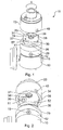
Figure 1 is a perspective view from above illustrating a coupling forming a first embodiment of the present invention, with the two parts thereof shown separated; -
Figure 2 is a perspective view from a different orientation illustrating the same components as inFigure 1 , separated in the same manner; -
Figure 3 is a cut-away perspective view of the coupling ofFigures 1 and 2 showing the coupling unit held in place on a base of the coupling during release thereof; -
Figure 4 is a cut-away perspective view similar to that ofFigure 3 , showing the relative positions of the pressure-sensitive interlock device after the interior pressure within the coupling has fallen to atmospheric pressure; -
Figure 5 is an axial sectional view on an enlarged scale through a different plane illustrating the manual interlock device; -
Figures 6 is a schematic view of the upper part of a pressurised gas cylinder having a first part of the modular coupling system of the present invention fitted thereto; -
Figure 7 is a similar perspective view of the upper part of a gas cylinder showing a utiliser device, in the form of a flow meter, releasably secured thereto using the modular coupling system of the present invention; -
Figure 8 is an axial sectional view through the first coupling part of a modular coupling system according to the invention; -
Figure 9 is a perspective view from above of the outer casing of the first coupling part illustrated inFigure 8 ; -
Figure 10 is a perspective view from below and one side of a second coupling part of the modular coupling system of the invention, adapted to be fitted to the first coupling part illustrated inFigures 8 and9 ; -
Figure 11 is a perspective view from below of the second coupling part illustrated inFigure 10 , shown from a different angle; and -
Figure 12 is a perspective view of the two coupling parts illustrated inFigures 8 to 11 fitted together in their assembled condition. - Referring first to
Figures 1 to 5 of the drawings, there is shown acoupling 11 for connection to a regulator indicated 10 attached to a gas cylinder (not shown) such as an oxygen cylinder, and comprising abase unit 12 and acoupling unit 13 shown spaced from one another in the drawings. Thebase unit 12 is intended to be permanently secured in position on one end of the gas cylinder (not shown) and as can be seen in the drawings, thebase unit 12 has a dependingcylindrical skirt 14 with three openings through which passfixing set screws 15 which secure thebase unit 12 in place on the cylinder. - The
base unit 12 has amain body 16 from which theskirt portion 14 depends, and themain body 16 is provided with a central passage 17 (seeFigures 3 and 4 ) housing a poppet valve generally indicated 18 having anoperating stem 19, and apiston head 20 which locates a sealingring 21 against ashoulder 22 at the upper end of themain gas passage 17. A biasingspring 23 acting between a lower radially inwardly projectingflange 24 at the lower end of thegas passage 17 and the under surface of thepiston 20 urges thepoppet valve 18 to the closure position in which theseal 21 is pressed against theshoulder 22. - As can be seen in
Figure 1 thestem 19 of thepoppet valve 18 projects through a central opening in thebody 16 of thebase unit 12. Themain body 16 of thebase unit 12 is in the form of a generallycylindrical turret 57 with two arcuately curvedperipheral sections rectilinear sections curved sections Figures 1 and 2 , namely that associated with the circumferential section 26). Thecircumferential sections grooves 29. At one end of each of theseflanges circumferential section 26, is visible inFigures 1 and 2 ) for a purpose which will be described in more detail below. - The upper flat surface of the
turret 57 of thebase unit 16, through which thestem 19 of themain delivery valve 18 projects, also has anarcuate slot 31 for a purpose which will be described in more detail below. - As can be seen in
Figure 2 thecoupling unit 13 comprises amain body portion 33 from which depends askirt portion 34 the lower rim of which has two radially inwardly directed part-circumferential flanges 35, 36 (seeFigure 2 ) so shaped that thecoupling unit 13 can only be placed in position on the base unit in one orientation, with theflanges coupling unit 13 with respect to thebase unit 12 then allows the radially inwardly directedflanges grooves 29 so that the radially outwardly projectingflanges flanges ramp portions 30 drawing the two parts axially together so that a sealingring 37 in acentral opening 38 in thecoupling unit 13 engages acentral boss 39 on theturret 57 of thebase unit 12. - The
skirt portion 34 of thecoupling unit 13 also has aradial aperture 40 which interengages with a resiliently biased manually-operable lock pin 41 carried on the body portion of thebase unit 12. Thispin 41 is shown in more detail inFigure 5 . It has a bull-nose radiallyouter end 42, and a hollowcentral portion 43 housing a biasing spring 44 which urges it radially outwardly to the position illustrated inFigures 1 and 2 , in which position it is held by interengagement of abutment means (not illustrated). By pressing on the bull-noserounded end 42 with a thumb or finger thepin 41 can be urged radially inwardly so that it is located within theaperture 40 whereupon relative turning movement of thecoupling unit 13 and thebase unit 12 presses thepin 41 further inwardly so that the bull-nose part 42 slides on the inner surface of theskirt portion 34 of thecoupling unit 13. - The
coupling unit 13 also carries a pressure-sensitive interlock device which can be seen best inFigure 4 . This comprises apiston 45 located within a cylindrical chamber and sealed with a sealingring 48. Thepiston 45 has an axially extendingpin 49 and is resilient biased by aspring 50 to the position illustrated inFigure 4 in which thelower end 51 of thepin 49 is substantially flush with or projects only slightly from alower surface 52 of thebody 33 of the coupling unit 13 (seeFigure 2 ), which shows thelower end 51 of thepin 49 just projecting below thesurface 52 of thebody 33 of thecoupling unit 13. - The upper end of the
cylindrical chamber 47 communicates via apassage 53 with agallery 54 in communication with acentral opening 55 through thebody 33 of thecoupling unit 13 leading to anoutlet connector 56. - In use the coupling can be made by depressing the
pin 41 manually to a position where the bull-nose portion 42 is approximately radially in register with the curved arcuate surface of theflange 26 of theturret 57 on the base unit allowing thecoupling unit 13 to be lowered over thebase unit 12 with the radially inwardly directedflanges rectilinear portions coupling unit 13 can be fitted in position in only one of the two possible orientations. Then, by rotating thecoupling unit 13 with respect to thebase unit 12 in a clockwise direction as viewed from above (illustrated by the arrow A inFigure 1 ) theflanges coupling unit 13 are brought under the "claw" of the radially outwardly projectingflanges turret 57, with theramp 30 causing the twoparts aperture 40 comes into register with the bull-nose 42 of thepin 41 whereupon thespring 43 urges the pin to enter thehole 40 to adopt the position illustrated inFigure 5 . In doing so thepin 19 of thepoppet valve 18 is depressed by the contacting undersurface of thebody 33 of thecoupling unit 13 causing it to move axially towards thegas cylinder 10 compressing thespring 23 and displacing the sealingring 21 from theshoulder 22 so that gas from the cylinder can flow through thepassage 55 into thegallery 54 and from there through theopening 53 into thecylindrical chamber 47 urging thepiston 45 downwards to press thepin 49 axially until thetip 51 thereof engages into thearcuate slot 31 of thebase unit 12. As the final connection is made a small amount of gas from thecylinder 10 escapes through the interface between thebase unit 12 and thecoupling unit 13 clearing out any dust or foreign bodies which may have collected there during storage. - In order to release the
coupling unit 13 from the gas container assembly comprising thecylinder 10 and thebase unit 12 it is necessary first to depress the bull-nose 42 with a thumb or finger whereupon thecoupling unit 13 can be rotated in an anticlockwise direction opposite that of the arrow A inFigure 1 through a small angle limited by the interengagement of thetip 51 of thepin 49 in thearcuate groove 31 in theturret 57 of thebase unit 12. This limited angular movement leaves the axial interengagement of the cooperating radially inwardly directedflanges coupling unit 13 and the radially outwardly directedflanges turret 57 in place so that axial separation of thecoupling unit 13 and thebase unit 12 cannot take place. Theramp 30 allows a limited amount of axial movement during this first limited arcuate turning of thecoupling unit 13 so that the pressure on thestem 19 of thepoppet valve 18 is released and thespring 23 can press the sealingring 21 against theshoulder 22 closing this valve. This closure is, of course, also reinforced by the pressure on thepiston head 20 of the valve from the gas compressed within thecontainer 10. The interior of thecoupling unit 13 is, however, at this point still under pressure as delivered by the regulator but this commences to vent through the now-open interface as illustrated by arrow B inFigure 3 . Such venting will also allow any compressed gas within the apparatus downstream of the container assembly (if such is fitted) to vent to the atmosphere. With the reduction in pressure within thecylinder 47 thespring 50 closes thepiston 45 and draws thetip 51 of thepin 49 out of thearcuate groove 31 allowing further rotation of thecoupling unit 13 to take place until theflanges coupling unit 13 are out of register with theflanges turret 57 of thebase unit 12 so that thecoupling unit 13 can be lifted off. - The connector spigot surrounding the
passage 56 on thecoupling unit 13 has been illustrated schematically simply for convenience although the precise form of this connector will depend on the nature of the apparatus to be connected to the container assembly. - The operation for separation of the
coupling unit 13 thus involves manual depression of thepin 41, a first partial twist of thecoupling unit 13 at which point gas escape will be heard, and once this gas has escaped further rotation of thecoupling unit 13 is possible allowing thecoupling unit 13 to be lifted and separated from thebase unit 13 quickly and safely. - Referring now to
Figure 6 , there is shown the upper part of a pressurisedgas canister 60 having a permanently securedgas pressure regulator 61 fitted thereto. As explained above, theregulator 61 may be secured to thegas canister 60 by fixing means which require specialist tools to remove it, or may be permanently secured in such a way that it is not removable from the gas canister. Thepressure regulator 61 has agauge 62 indicating the residual pressure of the gas within the canister. Typically, as mentioned above, the pressure regulator reduces the pressure of gas from the typical maximum charge value of 300 bar down to about 4 bar. - Permanently secured to the
pressure regulator 61 is afirst part 63 of a modular coupling system the form of which will be described in greater detail below. As can be seen inFigure 7 , the second part of the modular coupling system is in this embodiment integrally formed with agas utiliser device 64, in this case a flow meter, which is a device for accurately controlling the rate of flow of gas delivered through anoutlet spigot 67 to which an ultimate consumer device (such as breathing apparatus if the canister were filled with oxygen) is connected. The flow meter has anAdjustment control knob 65 turning which determines the precise rate of flow of gas through theutiliser device 64, and the selected value (of which there are typically in the region of eleven or twelve different settings) is shown through awindow 66. - As with the first embodiment, the
utiliser device 64 with incorporated second part of the modular coupling system can be removed quickly and easily from the gas bottle, in this embodiment by means of a simple, single twist operation. This operation closes a main gas delivery valve in thefirst coupling part 63 and vents to atmosphere the gas pressure within theutiliser device 64 and (if fitted) the ultimate consumer device connected to theoutlet spigot 67. A manuallyoperable latch 68 is provided to lock the two coupling parts against relative rotation and therefore inadvertent separation. Thelatch 68 is spring loaded into its engaged position, and can be lifted with a finger or thumb, to be urged axially of theutiliser device 64 away from thecanister 60 releasing the two coupling parts for predetermined limited relative twisting motion as will be described in more detail below. - Turning now to
Figures 8 and9 , thefirst coupling part 63 is illustrated in more detail. As can be seen inFigure 8 this coupling part has a cup-shapemain body 69 with a cylindrical depending skirt 70 having fourtransverse openings 71 through which fixings such as screws can be introduced to retain the skirt 70 on theintegral pressure regulator 61. - The bottom of the cup-shape body 69 (which is uppermost in
Figure 8 as the cup-shape body 69 is inverted in use) has acentral boss 71 having two axially extendingpassages Figure 8 . A transverse passage joins the twoaxial passages elongate slide valve 75 having two O-ring seals slide valve 75 has a bull-nose projectingfree end 78 at the open end of thepassage 74, and aradial flange 79 at the inner end engaging the sealingring 77. Acompression spring 80 urges theslide valve 75 to the left as illustrated inFigure 8 to a position where the sealingring 77 engages between theflange 79 and ashoulder 81 in thepassage 74 between acentral part 82 of thepassage 74 and anenlarged end part 83 thereof. Theenlarged part 83 of thepassage 74 is closed by anend cap 84 and sealingring 85. - The
passage 74 has an intermediate narrowedsection 86 into which the sealingring 76 enters when thebull nose end 78 is pressed (to the right as viewed inFigure 8 ) against the action of biasingspring 80. This action also separates the sealingring 77 from theshoulder 81 opening the valve formed thereby and allowing communication between theaxial passages flange 79, sealingring 77,shoulder 81 and biasingspring 80 thus constitutes the main delivery valve of the coupling assembly. - As can be seen in
Figure 9 , thecentral boss 71 of thebody 69 has anupper face 86 from which projects an eccentric axially extendingpin 87, the function of which will be explained in more detail below. A partlyannular ridge 88 of theboss 71 projects radially and defines an annular shoulder with two diametricallyopposed flats circumferential interruption 91, the purpose of which will be explained below. - The second coupling part illustrated in
Figures 10 and11 , in this embodiment formed integrally with a flow meter, has abody 101 with a downwardly dependingskirt 102 having two inwardly projecting arcuate ribs 103,104. - As can be seen in
Figures 10 and11 thelatch 68 described in relation toFigure 7 has aninternal abutment nose 105 which, when the first and second coupling parts are engaged together, locates in theinterruption 91 of the circumferentialradial rib 88. The second coupling part is fitted over the first coupling part with the inwardly projectingribs flats radial rib 88 of the first coupling part in which configuration a corner of theabutment member 105 engages against the upper face of the circumferentialradial rib 88 and is displaced axially as the coupling member incorporated in the flow meter is pressed down onto the first coupling part. Then, upon relative twisting of theflow meter 64 in relation to thefirst coupling part 63 the radially inwardly projectingribs radial rib 88 of the first coupling part and an inclined orramp face 106 of therib 103 engages thebull nose 78 of theslide valve 75 pressing this inwardly as the two coupling parts are turned in relation to one another. This moves the sealingring 76 into thenarrow portion 86 of thepassage 74 and closes the gas escape route and then (in the same movement) opens the main delivery valve constituted by the sealingring 77 andshoulder 81 allowing gas from the canister to pass through thepassage 73 into thepassage 72. Aspigot 107 in the centre of the cavity defined by the dependingskirt 102 engages asealing ring 108 in the outlet opening 109 from thefirst coupling part 69 guiding the gas into the flow meter. - The
pin 87 engages in anarcuate slot 110 in the end face of the inner cavity of the second coupling member to determine the relative orientation of the two components as they are fitted together and to limit the relative angular twisting movement which can take place. Thispin 87 andslot 110 combination also serves another function, namely that of ensuring that gas cylinders containing a given gas can only be fitted with utiliser devices intended for use with that gas. By suitably selecting the dimensions of thepin 87 and theslot 110 to match one another the connector can be made gas-specific and incorrect connection of, for example, oxygen utiliser devices to propane gas cylinders can be avoided. - The assembled unit as shown in
Figure 12 has anadjustment spindle 111 by which the rate of flow of gas through the unit can be determined. Thelatch 68, engaging in theinterruption 91 prevents relative rotation of the two coupling parts and therefore ensures that the unit cannot be inadvertently separated from the gas canister. When it is desired deliberately to remove the flow meter, for example to utilise the gas canister for another purpose, thelatch 68 is displaced axially away from the canister lifting theabutment end 103 out of theinterruption 91 in the circumferentialradial rib 88 and allowing the flow meter to be turned in relation to the first coupling part. A single, simple twist then disengages the cam-shape rib 103 from the bull-nose 78 of theslide valve 75 allowing thespring 80 to displace the slide valve closing the main delivery valve constituted by the sealingring 77 and theshoulder 88 and moving the sealingring 76 out of the narrowedportion 86 of thepassage 74 thereby opening an escape route for compressed gas in the flow meter through thepassage 72 and out around the sealing ring 76 (now in a larger part of the passage 74) and shortly thereafter theribs flats - Although specific reference has been made herein to the use of the coupling system with gas canisters containing a gas suitable for medical use (such as oxygen), it will be appreciated that the invention is not limited to such applications and can be used in any environment where a number of gas containers may need to be coupled to a variety of gas utiliser devices, or even where a single utiliser device is used but needs to be removed periodically, such as for recharging the container.
Claims (13)
- A pressurised gas container assembly of the type comprising: a container (60) with an integral flow regulator (10; 61), having means for releasably coupling said container to utiliser equipment such as a flow meter, conservor, flow indicator or delivery apparatus, wherein the releasable coupling means is a modular coupling system comprising: a first coupler part (12; 63) adapted to be fixedly secured to a pressurised gas container (60) in a substantially non-removable manner, and a second coupler part (13; 64) adapted to be fixedly secured to, or integrally formed with, said utiliser equipment such as a flow meter, conservor, flow indicator or delivery apparatus, the said first coupler part (12; 63) being provided with valve closure means (18; 75) and the coupling system having venting means (B; 72) allowing escape of trapped pressurised gas upon removal of said utiliser equipment such as a flow meter, conservor, flow indicator or delivery apparatus from said pressurised gas container before separation of the said two coupler parts (12; 63, 13; 64) takes place.
- A pressurised gas container assembly according to claim 1, wherein the modular coupling system further comprises means (51) for preventing separation of the second coupler part from the first coupler part until the pressure within the coupling unit has fallen below a predetermined threshold value by release of gas pressure within the coupling upon relative displacement of the two coupling parts (12; 13).
- A pressurised gas container assembly according to claim 1 or claim 2, in which the said first coupler part (12; 63) has a gas delivery valve (18; 75) resiliently biased (23; 80) to a closure position, the gas delivery valve having valve-operating member (19; 78) engaged in use by the second coupler part upon coupling together of the said two coupler parts.
- A pressurised gas container assembly according to claim 3, in which the said valve-operating member is a valve stem (19; 75) the displacement of which causes opening or closing of the valve.
- A pressurised gas container assembly according to claim 3 or claim 4, in which the coupler parts (12; 13) have a common axis and the said valve-operating member (19) is displaceable axially thereof to effect opening or closure of the gas delivery valve and the said second coupler part (13) has a helical or part-helical cam face (30) causing relative axial movement of the said first (12) and second (13) coupler parts, as they are turned with respect on one another about the said common axis.
- A pressurised gas container assembly according to claim 3 or claim 4, in which the coupler parts (63; 64) have a common axis and the valve-operating member (78) is displaceable transversely thereof to effect opening or closure of the gas delivery valve (75) as the two coupler parts are turned with respect to one another about the said common axis.
- A pressurised gas container assembly according to any of claims 3 to 6, in which the gas delivery valve (18; 75) is oriented such that the closing displacement of the said valve-biasing means is reinforced by the pressure of gas within the container.
- A pressurised gas container assembly according to any preceding claim, in which said venting means (B; 72) is linked to the gas delivery valve (18; 75) so as to be opened by the same valve arrangement as closes the gas delivery valve itself.
- A pressurised gas container assembly according to claim 8, in which the venting means comprise a valve sealing member carried on a stem of the gas delivery valve (18; 75) such that closure of the gas delivery valve and opening of the gas venting means (B; 72) take place in sequence upon displacement of the single valve-operating member constituted by the said valve stem (19; 75).
- A pressurised gas container assembly as claimed in any preceding claim, further including a safety interlock member (42; 68) which retains the said first and second coupler members in their coupled position against inadvertent separation thereof.
- A pressurised gas container assembly according to claim 10, in which the said safety interlock member is a latch (68) which is manually displaceable from a latching position to a release position in order to allow relative displacement of the said two coupler parts to commence separation thereof for release of the coupling.
- A pressurised gas container assembly as claimed in any preceding claim, further including male and female interconnecting parts (87, 110) on respective coupling parts the form and/or dimensions of which are related to the gas intended for use therewith whereby to inhibit interconnection of the coupling parts of systems intended for use with different gases.
- A pressurised gas container assembly according to any preceding claim, in which axial separation of the two coupler parts is resisted while the said two parts of the coupling means are moving between the engaged and the release positions thereof, by the interengagement of a part-circumferential radially outwardly projecting flange (25, 26; 88) or shoulder on one coupling part with a part-circumferential radially inwardly projecting flange, or shoulder (35, 36; 103, 104) on the other coupling part.
Applications Claiming Priority (2)
| Application Number | Priority Date | Filing Date | Title |
|---|---|---|---|
| GB0614239A GB0614239D0 (en) | 2006-07-18 | 2006-07-18 | Improvements in or relating to gas container assemblies and couplings therefor |
| PCT/GB2007/002731 WO2008009941A1 (en) | 2006-07-18 | 2007-07-18 | Improvements in or relating to gas container assemblies and couplings therefor |
Publications (2)
| Publication Number | Publication Date |
|---|---|
| EP2049829A1 EP2049829A1 (en) | 2009-04-22 |
| EP2049829B1 true EP2049829B1 (en) | 2011-04-20 |
Family
ID=36998259
Family Applications (1)
| Application Number | Title | Priority Date | Filing Date |
|---|---|---|---|
| EP20070789024 Not-in-force EP2049829B1 (en) | 2006-07-18 | 2007-07-18 | Improvements in or relating to gas container assemblies and couplings therefor |
Country Status (6)
| Country | Link |
|---|---|
| US (1) | US8353314B2 (en) |
| EP (1) | EP2049829B1 (en) |
| AT (1) | ATE506577T1 (en) |
| DE (1) | DE602007014054D1 (en) |
| GB (2) | GB0614239D0 (en) |
| WO (1) | WO2008009941A1 (en) |
Families Citing this family (21)
| Publication number | Priority date | Publication date | Assignee | Title |
|---|---|---|---|---|
| GB0806530D0 (en) * | 2008-04-10 | 2008-05-14 | Boc Group Plc | Tamper-resistant valve and connection arrangement |
| DE102008024231A1 (en) * | 2008-05-19 | 2009-11-26 | Bauer Kompressoren Gmbh | Filling connector |
| US8033293B2 (en) * | 2008-06-23 | 2011-10-11 | Tescom Corporation | Fluid regulator |
| DE102009045732B4 (en) * | 2009-10-15 | 2012-11-29 | Haldex Brake Products Gmbh | Valve for a compressed air system of a commercial vehicle |
| US9557747B2 (en) | 2010-12-23 | 2017-01-31 | Lincoln Global, Inc. | Gas flow regulator with multiple gas flow passages |
| EP2858593B1 (en) | 2012-06-12 | 2020-09-30 | Alcon Inc. | Intraocular gas injector |
| WO2014016957A1 (en) * | 2012-07-27 | 2014-01-30 | 有限会社カイト | Information-processing device, opening method, and opening program |
| GB201504451D0 (en) * | 2015-03-17 | 2015-04-29 | Linde Ag | A valve for a gas cylinder |
| JP6703837B2 (en) * | 2016-01-07 | 2020-06-03 | 株式会社神戸製鋼所 | Boil-off gas supply device |
| FR3054291B1 (en) * | 2016-07-20 | 2018-11-16 | Air Liquide | DEVICE FOR SUPPLYING FLUID UNDER PRESSURE |
| FR3054288B1 (en) * | 2016-07-20 | 2018-11-16 | L'air Liquide, Societe Anonyme Pour L'etude Et L'exploitation Des Procedes Georges Claude | DEVICE FOR SUPPLYING FLUID |
| AT519286B1 (en) | 2016-10-19 | 2018-12-15 | Gruber Dietmar | TWIN SCREW EXTRUDER |
| EP4233947B1 (en) * | 2018-04-16 | 2025-08-20 | Aeronics, Inc. | Portable gas delivery system |
| LU100807B1 (en) * | 2018-05-30 | 2019-12-02 | Luxembourg Patent Co | Gas flow device with gas flow selector mounted by insertion |
| FR3081965B1 (en) * | 2018-06-04 | 2020-05-08 | L'air Liquide, Societe Anonyme Pour L'etude Et L'exploitation Des Procedes Georges Claude | DEVICE FOR PROVIDING PRESSURE FLUID |
| US11224537B2 (en) | 2018-10-19 | 2022-01-18 | Alcon Inc. | Intraocular gas injector |
| FR3089600B1 (en) * | 2018-12-06 | 2021-03-19 | Air Liquide | Cryogenic fluid storage tank |
| FR3089599B1 (en) * | 2018-12-06 | 2020-11-13 | Air Liquide | Cryogenic fluid storage tank |
| FR3092894B1 (en) * | 2019-02-20 | 2021-10-15 | Air Liquide | Device for supplying pressurized fluid and bottle (s) for pressurized fluid comprising such a device |
| CA3231162C (en) * | 2021-09-07 | 2025-02-18 | Elizabeth Marie Bree | LINKING STRUCTURE AND CONTAINER ASSEMBLY TO FACILITATE THE TRANSFER OF LIQUID FROM A DONOR CONTAINER TO A RECEIVING CONTAINER |
| JP2025021556A (en) * | 2023-08-01 | 2025-02-14 | トヨタ自動車株式会社 | Hydrogen filling device for removable hydrogen tanks |
Family Cites Families (17)
| Publication number | Priority date | Publication date | Assignee | Title |
|---|---|---|---|---|
| GB1047122A (en) * | 1964-08-06 | 1966-11-02 | British Oxygen Co Ltd | Safety pressure disconnect device for pressure vessels |
| US3646965A (en) * | 1968-01-23 | 1972-03-07 | Oxygen Valve Co Of America | Gas supply connector and regulator valve |
| DE2851011A1 (en) * | 1977-11-25 | 1979-06-07 | Bristol Aerojet Ltd | VALVED COUPLING FOR HIGH PRESSURE FLUIDS |
| GB2111154B (en) * | 1981-11-17 | 1985-04-17 | Baj Vickers Ltd | Fluid flow couplings |
| US4479520A (en) * | 1981-11-20 | 1984-10-30 | The Coca-Cola Company | Balanced pressure coupling |
| US4586634A (en) * | 1984-03-12 | 1986-05-06 | Puritan-Bennett Corporation | Valve actuating latching coupler for high pressure device |
| SE442544B (en) * | 1984-09-17 | 1986-01-13 | Spiromec Ab | FILLING VALVE FOR FILLING GAS BOTTLES |
| US4809747A (en) * | 1987-07-31 | 1989-03-07 | General Motors Corporation | Quick disconnect device |
| ATE112372T1 (en) * | 1991-10-08 | 1994-10-15 | Klein Rectus App | SELF-BLEEDING QUICK CONNECT COUPLING FOR COMPRESSED GAS, ESPECIALLY COMPRESSED AIR LINES. |
| FR2724709B1 (en) * | 1994-09-16 | 1996-12-20 | Raymond Sperlich | CONNECTION DEVICE FOR PRESSURE FLUID CONTAINER TAP |
| US5445358A (en) * | 1994-12-16 | 1995-08-29 | Parker-Hannifin Corporation | Exhaust type quick action coupler |
| JP4087993B2 (en) * | 1998-08-13 | 2008-05-21 | 株式会社斎藤商会 | Socket for quick fitting |
| CA2333241A1 (en) * | 2001-01-30 | 2002-07-30 | Russell H. Barton | Coupling mechanism and valve system for a pressurized fluid container |
| ITTO20030160A1 (en) * | 2003-03-04 | 2004-09-05 | Pres Block Spa | TAKE-OFF BODY FOR A QUICK-RELEASE SAFETY COUPLING |
| US7153296B2 (en) * | 2003-11-07 | 2006-12-26 | Mitchell Martin S | Releasable tubing connector |
| US7401761B2 (en) * | 2004-05-13 | 2008-07-22 | Smart Parts, Inc. | Compressed gas cylinder safety device |
| JP2006093001A (en) * | 2004-09-27 | 2006-04-06 | Toshiba Corp | Coupler |
-
2006
- 2006-07-18 GB GB0614239A patent/GB0614239D0/en not_active Ceased
-
2007
- 2007-07-18 WO PCT/GB2007/002731 patent/WO2008009941A1/en not_active Ceased
- 2007-07-18 GB GB0713991A patent/GB2440268B/en not_active Expired - Fee Related
- 2007-07-18 EP EP20070789024 patent/EP2049829B1/en not_active Not-in-force
- 2007-07-18 DE DE200760014054 patent/DE602007014054D1/en active Active
- 2007-07-18 AT AT07789024T patent/ATE506577T1/en not_active IP Right Cessation
-
2009
- 2009-01-16 US US12/321,264 patent/US8353314B2/en not_active Expired - Fee Related
Also Published As
| Publication number | Publication date |
|---|---|
| US8353314B2 (en) | 2013-01-15 |
| GB2440268B (en) | 2011-05-04 |
| GB0713991D0 (en) | 2007-08-29 |
| EP2049829A1 (en) | 2009-04-22 |
| GB2440268A (en) | 2008-01-23 |
| ATE506577T1 (en) | 2011-05-15 |
| WO2008009941A1 (en) | 2008-01-24 |
| GB0614239D0 (en) | 2006-08-30 |
| US20090166226A1 (en) | 2009-07-02 |
| DE602007014054D1 (en) | 2011-06-01 |
Similar Documents
| Publication | Publication Date | Title |
|---|---|---|
| US8353314B2 (en) | Gas container assemblies and couplings therefor | |
| US8800826B2 (en) | Self-venting spout | |
| EP2596277B1 (en) | Closure device | |
| US6817390B2 (en) | Keyed anesthetic vaporizer filling system | |
| US6230737B1 (en) | Cylinder valve assembly | |
| US4574988A (en) | Pressure vessel for receiving liquids | |
| KR102655255B1 (en) | rechargeable oxygen respirator with one body type decompression valve | |
| US6941938B2 (en) | Adapter assembly with floating pin for operably connecting pressurized bottle to a paintball marker | |
| EP0220193B1 (en) | Filling valve | |
| NZ588449A (en) | Pneumatically operated pilot valve for gas cylinder and connection arrangement. | |
| JPH01119265A (en) | Safety filler for filling in and exhausting from evaporator for anesthetic agent | |
| EP2052754B1 (en) | Disposable absorber having an adapter and a lip seal | |
| US4637387A (en) | Breathing apparatus | |
| US20060272077A1 (en) | Protective mask drinking tube coupling device and method of use | |
| JP6131958B2 (en) | Gas container valve with flywheel for controlling residual pressure valve and stop valve | |
| US4341245A (en) | Gas inlet attachment for a gas charger | |
| US5960841A (en) | Filling yoke for compressed gas cylinders | |
| EP1540211B1 (en) | Cylinder valve | |
| US3229716A (en) | Cylinder valve unit | |
| US5996654A (en) | Quick-connect filling device for transferring fluids to a valve | |
| CN113335751B (en) | Hose for an extraction system and method for extracting a liquid from a container using an extraction system | |
| AU2005243566B2 (en) | Coupling device for a compressed gas cylinder | |
| CA2412695C (en) | Gas delivery system and pneumatic yoke for a pressurized gas reservoir | |
| US20140109823A1 (en) | Tank Pressure Indicator | |
| CN103442769B (en) | For the valve hand wheel of the improvement of self-carrying breathing apparatus |
Legal Events
| Date | Code | Title | Description |
|---|---|---|---|
| PUAI | Public reference made under article 153(3) epc to a published international application that has entered the european phase |
Free format text: ORIGINAL CODE: 0009012 |
|
| 17P | Request for examination filed |
Effective date: 20090217 |
|
| AK | Designated contracting states |
Kind code of ref document: A1 Designated state(s): AT BE BG CH CY CZ DE DK EE ES FI FR GB GR HU IE IS IT LI LT LU LV MC MT NL PL PT RO SE SI SK TR |
|
| AX | Request for extension of the european patent |
Extension state: AL BA HR MK RS |
|
| 17Q | First examination report despatched |
Effective date: 20090428 |
|
| GRAP | Despatch of communication of intention to grant a patent |
Free format text: ORIGINAL CODE: EPIDOSNIGR1 |
|
| GRAS | Grant fee paid |
Free format text: ORIGINAL CODE: EPIDOSNIGR3 |
|
| GRAA | (expected) grant |
Free format text: ORIGINAL CODE: 0009210 |
|
| AK | Designated contracting states |
Kind code of ref document: B1 Designated state(s): AT BE BG CH CY CZ DE DK EE ES FI FR GB GR HU IE IS IT LI LT LU LV MC MT NL PL PT RO SE SI SK TR |
|
| REG | Reference to a national code |
Ref country code: GB Ref legal event code: FG4D |
|
| REG | Reference to a national code |
Ref country code: CH Ref legal event code: EP |
|
| REG | Reference to a national code |
Ref country code: IE Ref legal event code: FG4D |
|
| REF | Corresponds to: |
Ref document number: 602007014054 Country of ref document: DE Date of ref document: 20110601 Kind code of ref document: P |
|
| REG | Reference to a national code |
Ref country code: DE Ref legal event code: R096 Ref document number: 602007014054 Country of ref document: DE Effective date: 20110601 |
|
| REG | Reference to a national code |
Ref country code: NL Ref legal event code: VDEP Effective date: 20110420 |
|
| LTIE | Lt: invalidation of european patent or patent extension |
Effective date: 20110420 |
|
| PG25 | Lapsed in a contracting state [announced via postgrant information from national office to epo] |
Ref country code: LT Free format text: LAPSE BECAUSE OF FAILURE TO SUBMIT A TRANSLATION OF THE DESCRIPTION OR TO PAY THE FEE WITHIN THE PRESCRIBED TIME-LIMIT Effective date: 20110420 Ref country code: PT Free format text: LAPSE BECAUSE OF FAILURE TO SUBMIT A TRANSLATION OF THE DESCRIPTION OR TO PAY THE FEE WITHIN THE PRESCRIBED TIME-LIMIT Effective date: 20110822 Ref country code: SE Free format text: LAPSE BECAUSE OF FAILURE TO SUBMIT A TRANSLATION OF THE DESCRIPTION OR TO PAY THE FEE WITHIN THE PRESCRIBED TIME-LIMIT Effective date: 20110420 |
|
| PG25 | Lapsed in a contracting state [announced via postgrant information from national office to epo] |
Ref country code: ES Free format text: LAPSE BECAUSE OF FAILURE TO SUBMIT A TRANSLATION OF THE DESCRIPTION OR TO PAY THE FEE WITHIN THE PRESCRIBED TIME-LIMIT Effective date: 20110731 Ref country code: IS Free format text: LAPSE BECAUSE OF FAILURE TO SUBMIT A TRANSLATION OF THE DESCRIPTION OR TO PAY THE FEE WITHIN THE PRESCRIBED TIME-LIMIT Effective date: 20110820 Ref country code: GR Free format text: LAPSE BECAUSE OF FAILURE TO SUBMIT A TRANSLATION OF THE DESCRIPTION OR TO PAY THE FEE WITHIN THE PRESCRIBED TIME-LIMIT Effective date: 20110721 Ref country code: BE Free format text: LAPSE BECAUSE OF FAILURE TO SUBMIT A TRANSLATION OF THE DESCRIPTION OR TO PAY THE FEE WITHIN THE PRESCRIBED TIME-LIMIT Effective date: 20110420 Ref country code: AT Free format text: LAPSE BECAUSE OF FAILURE TO SUBMIT A TRANSLATION OF THE DESCRIPTION OR TO PAY THE FEE WITHIN THE PRESCRIBED TIME-LIMIT Effective date: 20110420 Ref country code: CY Free format text: LAPSE BECAUSE OF FAILURE TO SUBMIT A TRANSLATION OF THE DESCRIPTION OR TO PAY THE FEE WITHIN THE PRESCRIBED TIME-LIMIT Effective date: 20110420 Ref country code: SI Free format text: LAPSE BECAUSE OF FAILURE TO SUBMIT A TRANSLATION OF THE DESCRIPTION OR TO PAY THE FEE WITHIN THE PRESCRIBED TIME-LIMIT Effective date: 20110420 Ref country code: FI Free format text: LAPSE BECAUSE OF FAILURE TO SUBMIT A TRANSLATION OF THE DESCRIPTION OR TO PAY THE FEE WITHIN THE PRESCRIBED TIME-LIMIT Effective date: 20110420 Ref country code: LV Free format text: LAPSE BECAUSE OF FAILURE TO SUBMIT A TRANSLATION OF THE DESCRIPTION OR TO PAY THE FEE WITHIN THE PRESCRIBED TIME-LIMIT Effective date: 20110420 |
|
| PG25 | Lapsed in a contracting state [announced via postgrant information from national office to epo] |
Ref country code: MT Free format text: LAPSE BECAUSE OF FAILURE TO SUBMIT A TRANSLATION OF THE DESCRIPTION OR TO PAY THE FEE WITHIN THE PRESCRIBED TIME-LIMIT Effective date: 20110420 Ref country code: NL Free format text: LAPSE BECAUSE OF FAILURE TO SUBMIT A TRANSLATION OF THE DESCRIPTION OR TO PAY THE FEE WITHIN THE PRESCRIBED TIME-LIMIT Effective date: 20110420 |
|
| PG25 | Lapsed in a contracting state [announced via postgrant information from national office to epo] |
Ref country code: CZ Free format text: LAPSE BECAUSE OF FAILURE TO SUBMIT A TRANSLATION OF THE DESCRIPTION OR TO PAY THE FEE WITHIN THE PRESCRIBED TIME-LIMIT Effective date: 20110420 Ref country code: EE Free format text: LAPSE BECAUSE OF FAILURE TO SUBMIT A TRANSLATION OF THE DESCRIPTION OR TO PAY THE FEE WITHIN THE PRESCRIBED TIME-LIMIT Effective date: 20110420 |
|
| PLBE | No opposition filed within time limit |
Free format text: ORIGINAL CODE: 0009261 |
|
| STAA | Information on the status of an ep patent application or granted ep patent |
Free format text: STATUS: NO OPPOSITION FILED WITHIN TIME LIMIT |
|
| PG25 | Lapsed in a contracting state [announced via postgrant information from national office to epo] |
Ref country code: DK Free format text: LAPSE BECAUSE OF FAILURE TO SUBMIT A TRANSLATION OF THE DESCRIPTION OR TO PAY THE FEE WITHIN THE PRESCRIBED TIME-LIMIT Effective date: 20110420 Ref country code: RO Free format text: LAPSE BECAUSE OF FAILURE TO SUBMIT A TRANSLATION OF THE DESCRIPTION OR TO PAY THE FEE WITHIN THE PRESCRIBED TIME-LIMIT Effective date: 20110420 Ref country code: SK Free format text: LAPSE BECAUSE OF FAILURE TO SUBMIT A TRANSLATION OF THE DESCRIPTION OR TO PAY THE FEE WITHIN THE PRESCRIBED TIME-LIMIT Effective date: 20110420 Ref country code: MC Free format text: LAPSE BECAUSE OF NON-PAYMENT OF DUE FEES Effective date: 20110731 Ref country code: PL Free format text: LAPSE BECAUSE OF FAILURE TO SUBMIT A TRANSLATION OF THE DESCRIPTION OR TO PAY THE FEE WITHIN THE PRESCRIBED TIME-LIMIT Effective date: 20110420 |
|
| REG | Reference to a national code |
Ref country code: CH Ref legal event code: PL |
|
| 26N | No opposition filed |
Effective date: 20120123 |
|
| REG | Reference to a national code |
Ref country code: IE Ref legal event code: MM4A |
|
| PG25 | Lapsed in a contracting state [announced via postgrant information from national office to epo] |
Ref country code: CH Free format text: LAPSE BECAUSE OF NON-PAYMENT OF DUE FEES Effective date: 20110731 Ref country code: LI Free format text: LAPSE BECAUSE OF NON-PAYMENT OF DUE FEES Effective date: 20110731 |
|
| REG | Reference to a national code |
Ref country code: DE Ref legal event code: R097 Ref document number: 602007014054 Country of ref document: DE Effective date: 20120123 |
|
| PG25 | Lapsed in a contracting state [announced via postgrant information from national office to epo] |
Ref country code: IT Free format text: LAPSE BECAUSE OF FAILURE TO SUBMIT A TRANSLATION OF THE DESCRIPTION OR TO PAY THE FEE WITHIN THE PRESCRIBED TIME-LIMIT Effective date: 20110420 |
|
| PG25 | Lapsed in a contracting state [announced via postgrant information from national office to epo] |
Ref country code: IE Free format text: LAPSE BECAUSE OF NON-PAYMENT OF DUE FEES Effective date: 20110718 |
|
| PG25 | Lapsed in a contracting state [announced via postgrant information from national office to epo] |
Ref country code: LU Free format text: LAPSE BECAUSE OF NON-PAYMENT OF DUE FEES Effective date: 20110718 |
|
| PG25 | Lapsed in a contracting state [announced via postgrant information from national office to epo] |
Ref country code: BG Free format text: LAPSE BECAUSE OF FAILURE TO SUBMIT A TRANSLATION OF THE DESCRIPTION OR TO PAY THE FEE WITHIN THE PRESCRIBED TIME-LIMIT Effective date: 20110720 |
|
| PG25 | Lapsed in a contracting state [announced via postgrant information from national office to epo] |
Ref country code: TR Free format text: LAPSE BECAUSE OF FAILURE TO SUBMIT A TRANSLATION OF THE DESCRIPTION OR TO PAY THE FEE WITHIN THE PRESCRIBED TIME-LIMIT Effective date: 20110420 |
|
| PG25 | Lapsed in a contracting state [announced via postgrant information from national office to epo] |
Ref country code: HU Free format text: LAPSE BECAUSE OF FAILURE TO SUBMIT A TRANSLATION OF THE DESCRIPTION OR TO PAY THE FEE WITHIN THE PRESCRIBED TIME-LIMIT Effective date: 20110420 |
|
| REG | Reference to a national code |
Ref country code: FR Ref legal event code: PLFP Year of fee payment: 9 |
|
| PGFP | Annual fee paid to national office [announced via postgrant information from national office to epo] |
Ref country code: GB Payment date: 20150709 Year of fee payment: 9 Ref country code: DE Payment date: 20150713 Year of fee payment: 9 |
|
| PGFP | Annual fee paid to national office [announced via postgrant information from national office to epo] |
Ref country code: FR Payment date: 20150717 Year of fee payment: 9 |
|
| REG | Reference to a national code |
Ref country code: DE Ref legal event code: R119 Ref document number: 602007014054 Country of ref document: DE |
|
| GBPC | Gb: european patent ceased through non-payment of renewal fee |
Effective date: 20160718 |
|
| PG25 | Lapsed in a contracting state [announced via postgrant information from national office to epo] |
Ref country code: DE Free format text: LAPSE BECAUSE OF NON-PAYMENT OF DUE FEES Effective date: 20170201 Ref country code: FR Free format text: LAPSE BECAUSE OF NON-PAYMENT OF DUE FEES Effective date: 20160801 |
|
| REG | Reference to a national code |
Ref country code: FR Ref legal event code: ST Effective date: 20170331 |
|
| PG25 | Lapsed in a contracting state [announced via postgrant information from national office to epo] |
Ref country code: GB Free format text: LAPSE BECAUSE OF NON-PAYMENT OF DUE FEES Effective date: 20160718 |