EP2049182B1 - Method of micropleating a catheter balloon with multiple micropleats - Google Patents
Method of micropleating a catheter balloon with multiple micropleats Download PDFInfo
- Publication number
- EP2049182B1 EP2049182B1 EP07836458.5A EP07836458A EP2049182B1 EP 2049182 B1 EP2049182 B1 EP 2049182B1 EP 07836458 A EP07836458 A EP 07836458A EP 2049182 B1 EP2049182 B1 EP 2049182B1
- Authority
- EP
- European Patent Office
- Prior art keywords
- balloon
- micropleats
- inflated
- folds
- Prior art date
- Legal status (The legal status is an assumption and is not a legal conclusion. Google has not performed a legal analysis and makes no representation as to the accuracy of the status listed.)
- Active
Links
- 238000000034 method Methods 0.000 title claims description 16
- 229920000642 polymer Polymers 0.000 claims description 39
- 239000000463 material Substances 0.000 claims description 27
- 229920001296 polysiloxane Polymers 0.000 claims description 21
- 229920002313 fluoropolymer Polymers 0.000 claims description 7
- 239000004811 fluoropolymer Substances 0.000 claims description 7
- 229920001971 elastomer Polymers 0.000 claims description 6
- 239000000806 elastomer Substances 0.000 claims description 6
- 229920001343 polytetrafluoroethylene Polymers 0.000 claims description 6
- 239000004810 polytetrafluoroethylene Substances 0.000 claims description 6
- JOYRKODLDBILNP-UHFFFAOYSA-N Ethyl urethane Chemical compound CCOC(N)=O JOYRKODLDBILNP-UHFFFAOYSA-N 0.000 claims description 3
- 238000009998 heat setting Methods 0.000 claims 1
- 238000005096 rolling process Methods 0.000 claims 1
- 238000007789 sealing Methods 0.000 claims 1
- 239000010410 layer Substances 0.000 description 26
- 230000003014 reinforcing effect Effects 0.000 description 19
- 239000002131 composite material Substances 0.000 description 9
- 238000013461 design Methods 0.000 description 9
- 239000012528 membrane Substances 0.000 description 7
- 208000014674 injury Diseases 0.000 description 4
- 239000002904 solvent Substances 0.000 description 4
- 230000008733 trauma Effects 0.000 description 4
- 208000027418 Wounds and injury Diseases 0.000 description 3
- 210000001367 artery Anatomy 0.000 description 3
- 230000017531 blood circulation Effects 0.000 description 3
- 239000011248 coating agent Substances 0.000 description 3
- 238000000576 coating method Methods 0.000 description 3
- 238000011161 development Methods 0.000 description 3
- 230000018109 developmental process Effects 0.000 description 3
- 239000011159 matrix material Substances 0.000 description 3
- 239000003094 microcapsule Substances 0.000 description 3
- 238000012856 packing Methods 0.000 description 3
- 229920000728 polyester Polymers 0.000 description 3
- -1 polyethylene Polymers 0.000 description 3
- 229920002635 polyurethane Polymers 0.000 description 3
- 239000004814 polyurethane Substances 0.000 description 3
- 239000004952 Polyamide Substances 0.000 description 2
- 208000012287 Prolapse Diseases 0.000 description 2
- 125000001931 aliphatic group Chemical group 0.000 description 2
- 125000003118 aryl group Chemical group 0.000 description 2
- 230000004323 axial length Effects 0.000 description 2
- BASFCYQUMIYNBI-UHFFFAOYSA-N platinum Chemical compound [Pt] BASFCYQUMIYNBI-UHFFFAOYSA-N 0.000 description 2
- 229920002647 polyamide Polymers 0.000 description 2
- 229920006132 styrene block copolymer Polymers 0.000 description 2
- 229920001169 thermoplastic Polymers 0.000 description 2
- 239000004416 thermosoftening plastic Substances 0.000 description 2
- 208000031481 Pathologic Constriction Diseases 0.000 description 1
- 239000004696 Poly ether ether ketone Substances 0.000 description 1
- 239000004698 Polyethylene Substances 0.000 description 1
- 229920009638 Tetrafluoroethylene-Hexafluoropropylene-Vinylidenefluoride Copolymer Polymers 0.000 description 1
- 239000004433 Thermoplastic polyurethane Substances 0.000 description 1
- 150000001336 alkenes Chemical class 0.000 description 1
- 210000003484 anatomy Anatomy 0.000 description 1
- 238000002399 angioplasty Methods 0.000 description 1
- 238000013459 approach Methods 0.000 description 1
- 238000005452 bending Methods 0.000 description 1
- JUPQTSLXMOCDHR-UHFFFAOYSA-N benzene-1,4-diol;bis(4-fluorophenyl)methanone Chemical compound OC1=CC=C(O)C=C1.C1=CC(F)=CC=C1C(=O)C1=CC=C(F)C=C1 JUPQTSLXMOCDHR-UHFFFAOYSA-N 0.000 description 1
- 230000015572 biosynthetic process Effects 0.000 description 1
- 230000006835 compression Effects 0.000 description 1
- 238000007906 compression Methods 0.000 description 1
- 238000007796 conventional method Methods 0.000 description 1
- 229920001577 copolymer Polymers 0.000 description 1
- 230000007423 decrease Effects 0.000 description 1
- 230000003247 decreasing effect Effects 0.000 description 1
- 230000010339 dilation Effects 0.000 description 1
- 239000003814 drug Substances 0.000 description 1
- 229940079593 drug Drugs 0.000 description 1
- 229920000295 expanded polytetrafluoroethylene Polymers 0.000 description 1
- 229920001973 fluoroelastomer Polymers 0.000 description 1
- 230000002706 hydrostatic effect Effects 0.000 description 1
- 238000001727 in vivo Methods 0.000 description 1
- 238000003475 lamination Methods 0.000 description 1
- 229920000126 latex Polymers 0.000 description 1
- 239000004816 latex Substances 0.000 description 1
- 238000012986 modification Methods 0.000 description 1
- 230000004048 modification Effects 0.000 description 1
- JRZJOMJEPLMPRA-UHFFFAOYSA-N olefin Natural products CCCCCCCC=C JRZJOMJEPLMPRA-UHFFFAOYSA-N 0.000 description 1
- 230000010412 perfusion Effects 0.000 description 1
- 239000004033 plastic Substances 0.000 description 1
- 229920003023 plastic Polymers 0.000 description 1
- 229910052697 platinum Inorganic materials 0.000 description 1
- 229920002530 polyetherether ketone Polymers 0.000 description 1
- 229920000573 polyethylene Polymers 0.000 description 1
- 229920000098 polyolefin Polymers 0.000 description 1
- 239000011148 porous material Substances 0.000 description 1
- 230000002265 prevention Effects 0.000 description 1
- 238000007763 reverse roll coating Methods 0.000 description 1
- 238000004904 shortening Methods 0.000 description 1
- 239000002356 single layer Substances 0.000 description 1
- 229910001220 stainless steel Inorganic materials 0.000 description 1
- 239000010935 stainless steel Substances 0.000 description 1
- 230000036262 stenosis Effects 0.000 description 1
- 208000037804 stenosis Diseases 0.000 description 1
- 229920002803 thermoplastic polyurethane Polymers 0.000 description 1
- 238000012546 transfer Methods 0.000 description 1
- 150000003673 urethanes Chemical class 0.000 description 1
- 210000003462 vein Anatomy 0.000 description 1
Images


Classifications
-
- A—HUMAN NECESSITIES
- A61—MEDICAL OR VETERINARY SCIENCE; HYGIENE
- A61M—DEVICES FOR INTRODUCING MEDIA INTO, OR ONTO, THE BODY; DEVICES FOR TRANSDUCING BODY MEDIA OR FOR TAKING MEDIA FROM THE BODY; DEVICES FOR PRODUCING OR ENDING SLEEP OR STUPOR
- A61M25/00—Catheters; Hollow probes
- A61M25/10—Balloon catheters
- A61M25/1002—Balloon catheters characterised by balloon shape
-
- A—HUMAN NECESSITIES
- A61—MEDICAL OR VETERINARY SCIENCE; HYGIENE
- A61M—DEVICES FOR INTRODUCING MEDIA INTO, OR ONTO, THE BODY; DEVICES FOR TRANSDUCING BODY MEDIA OR FOR TAKING MEDIA FROM THE BODY; DEVICES FOR PRODUCING OR ENDING SLEEP OR STUPOR
- A61M25/00—Catheters; Hollow probes
- A61M25/10—Balloon catheters
- A61M25/1027—Making of balloon catheters
- A61M25/1038—Wrapping or folding devices for use with balloon catheters
-
- A—HUMAN NECESSITIES
- A61—MEDICAL OR VETERINARY SCIENCE; HYGIENE
- A61M—DEVICES FOR INTRODUCING MEDIA INTO, OR ONTO, THE BODY; DEVICES FOR TRANSDUCING BODY MEDIA OR FOR TAKING MEDIA FROM THE BODY; DEVICES FOR PRODUCING OR ENDING SLEEP OR STUPOR
- A61M25/00—Catheters; Hollow probes
- A61M25/10—Balloon catheters
- A61M25/1002—Balloon catheters characterised by balloon shape
- A61M2025/1004—Balloons with folds, e.g. folded or multifolded
-
- A—HUMAN NECESSITIES
- A61—MEDICAL OR VETERINARY SCIENCE; HYGIENE
- A61M—DEVICES FOR INTRODUCING MEDIA INTO, OR ONTO, THE BODY; DEVICES FOR TRANSDUCING BODY MEDIA OR FOR TAKING MEDIA FROM THE BODY; DEVICES FOR PRODUCING OR ENDING SLEEP OR STUPOR
- A61M25/00—Catheters; Hollow probes
- A61M25/10—Balloon catheters
- A61M25/1027—Making of balloon catheters
- A61M25/1029—Production methods of the balloon members, e.g. blow-moulding, extruding, deposition or by wrapping a plurality of layers of balloon material around a mandril
- A61M2025/1031—Surface processing of balloon members, e.g. coating or deposition; Mounting additional parts onto the balloon member's surface
-
- A—HUMAN NECESSITIES
- A61—MEDICAL OR VETERINARY SCIENCE; HYGIENE
- A61M—DEVICES FOR INTRODUCING MEDIA INTO, OR ONTO, THE BODY; DEVICES FOR TRANSDUCING BODY MEDIA OR FOR TAKING MEDIA FROM THE BODY; DEVICES FOR PRODUCING OR ENDING SLEEP OR STUPOR
- A61M25/00—Catheters; Hollow probes
- A61M25/10—Balloon catheters
- A61M2025/1043—Balloon catheters with special features or adapted for special applications
- A61M2025/1086—Balloon catheters with special features or adapted for special applications having a special balloon surface topography, e.g. pores, protuberances, spikes or grooves
Definitions
- Catheter balloon designs have incorporated various methods with the intent of attaining a low catheter profile.
- a low catheter profile is desirable because it reduces the likelihood of catheter based complications.
- lower profiles allow use of the catheter in tortuous paths and therefore enable access to more parts of an anatomy, and allow use of smaller guide catheters.
- the previous approach to minimizing catheter profiles involves the use of materials which allow formation of thinner balloon walls which are subsequently folded and packed to achieve lower profiles. While such designs achieve relatively low catheter profiles, they fail to produce designs conducive to uniform stent deployment.
- wings Those balloon designs that have achieved greater uniformity in stent deployment generally exhibit multiple folds, also known as "wings" or “pleats". Packing designs known in the art include tri-folded balloon profiles and other multiple canted wing profiles. These packing designs are not known to achieve a uniform expansion when used in stenosis dilation procedures, thus increasing the likelihood of contributing to arterial trauma. Also, non-uniform stent deployment leads to non-uniform stent cell size per area, which may lead to tissue and/or plaque prolapse, which in turn results in a smaller luminal area for blood flow.
- US 6,013,092 relates to methods for folding a catheter mounted balloon.
- the methods generally comprise folding a balloon portion that is in a flattened configuration at least twice, in opposite directions, so that any rotational forces created by the unfolding of the balloon as it is inflated will counteract each other.
- Catheter balloons having longitudinal furrows; and catheters and systems for implanting endoluminal devices with such balloons are also disclosed.
- US 2002/0163104 relates to an apparatus for folding a catheter balloon in two steps. In the first step the balloon is folded into a shape with curved wings and angled wing bases (a spiral-pleated shape) and in the second step the balloon is folded tightly round the shaft by means of radial compression through a diameter reduction.
- US 5,308,356 relates to a passive perfusion angioplasty catheter which defines at least one passage between a surface of the balloon and the interior wall of an artery to permit blood flow therethrough when the balloon member is pressed against the artery wall. Examples of pleated balloon members, which provide the passage for blood flow are described and illustrated.
- US 2003/0131716 relates to a non-compliant balloon with compliant top layer to protect coated stents during expansion.
- the balloon In the uninflated/deflated state the balloon comprises longitudinal wings, which wrap around the longitudinal axis of the non-compliant balloon.
- EP 0 737 488 relates to a balloon catheter with a lobated balloon.
- the expandable balloon member comprises a number of relatively stiff sections extending on a small diameter in a longitudinal direction of the basic body and relatively pliable sections extending in between wherein the relatively pliable sections form lobes in an expanded state of the balloon member.
- US 5,893,840 relates to a balloon catheter which comprises microcapsules of a drug on its surface.
- these microcapsules are held in place mechanically by folds in the balloon. As the balloon inflates, the folds are eliminated which expels the microcapsules into the treatment site.
- the present invention provides a method of forming the micropleats on a balloon according to claim 1.
- the examples provides a catheter balloon formed of at least one balloon material having a longitudinal axis with micropleats distributed about the circumference of the balloon resulting in a low profile and an essential symmetry upon inflation.
- the balloon of the examples is able to achieve a low profile due to smaller introducer sheath requirements. Additionally, the balloon reduces vessel trauma through radial concentric inflation of the balloon itself.
- micropleats reduce the entry profile of the balloon and are formed to pull taut in an inflated state.
- the catheter balloon 2 is formed of at least one balloon material 4.
- the balloon material is formed into a balloon having a longitudinal axis and micropleats 8 formed into the balloon.
- Balloon pleat size and distribution is a function of the inflated diameter, non-inflated diameter and the thickness of the balloon material.
- the micropleats 8 are invaginated areas of folded balloon material 4 with at least one fold 5 or bend which forms a pocket 10 of balloon material.
- the pocket comprises an opening 11 and at least one side of the pocket and a bottom 12 of the pocket 10.
- the inside of the pocket is a cavity wherein the most distant part of the pocket is adjacent to the bottom of the pocket.
- the side 13 of the pocket runs from the balloon opening to the bottom of the pocket flanking the opening to the pocket.
- the opening 11 is ideally located opposite of the bottom 12 of the pocket.
- the micropleats 8 are distributed about the circumference of the balloon.
- the bottom of each micropleat pocket is oriented such that it is free of contact or overlap with any other portion of an adjacent micropleat.
- Each micropleat has at least one fold 5 which allows balloon material to be stored upon itself. While the micropleats are depicted as running longitudinally in the direction of the axis, helical orientations, S-shaped orientations and other configurations of micropleat distribution may be formed.
- the material is folded upon itself to form at least one pocket so that at least 50% of the pocket bottoms are located on the inside of the balloon juxtaposed to the balloon lumen in an uninflated state.
- at least 75% of the pocket bottoms are located on the inside of the balloon juxtaposed to the balloon lumen.
- at least 90% of the pocket bottoms are located on the inside of the balloon juxtaposed to the balloon lumen.
- the catheter balloon has a longitudinal axis with an inner lumen and at least one balloon material forming an outer circumference and at least one micropleat.
- the micropleat comprises a pocket of balloon material having an opening commencing at the lumen, a bottom and sides where each side folds upon itself to connect the bottom of the pocket to the opening.
- the micropleat reduces profile and stores the balloon material in a folded configuration until inflation.
- the micropleats are formed to pull taut in an inflated state. Upon inflation pressure, the balloon exhibits essentially radially symmetric inflation and imparts an equal hydrostatic load during clinical use.
- Radially symmetric inflation is exhibited when a balloon in an uninflated state can be shown to expand with inflation pressure in a manner allowing points on the balloon to maintain proportionate spacing with each other in the inflated state.
- the radial inflation symmetry of the balloon also contributes to uniform stent deployment. Such uniform radial inflation has been found to reduce trauma to the vessels into which the balloon is deployed.
- Figure 2 shows a cross section of a traditional folded balloon design, As can be seen, the material is folded upon itself with long folds wrapped around the lumen 6 of the balloon. In this folding pattern, the folds overlap adjacent folds of the balloon around the lumen 6. Internal inflation pressure enters the opening to the pocket and then fills the cavities prior to the pocket sides shortening, thus causing a non-symmetric inflation. As seen in Figure 1 , the short walls of the micropleats grow circumferentially upon the addition of an inflation pressure, allowing a symmetrical inflation. The micropleats are symmetric and uniform in their distribution. The micropleats may be oriented in different ways. In one example, as shown in Figure 3 , the micropleats 8 are oriented longitudinally, i.e.
- the longitudinal micropleats are evenly distributed about the circumference of the balloon diameter.
- a balloon seal 16 may be present, distinct from the inflatable balloon portion, if desired, on the catheter shaft 14.
- the number of micropleats in the balloon may vary, but should be at least six pleats or greater. In a preferred example, the balloon diameter is 1.0 mm or less. However, the micropleats may be utilized on any size balloon. In an inflated state as shown in Figure 4 , the micropleats 8 of the balloon pull taut such that they are not visible.
- the micropleats may be arranged on a formed balloon 2 or on a tubular structure of balloon material.
- an uninflated balloon may be adhered to a catheter shaft 14 and then inflated to achieve an inflated outer diameter.
- a compressive radial force is then applied to the inflated outer diameter of the balloon to cause deflation of the balloon and create longitudinal folds in the balloon material 4.
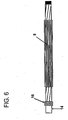
- heat, along with a compressive force is applied so that the balloon maintains its micropleated structure (see Figure 6 ).
- the number of pleats generally increases as the ratio of inflated balloon diameter to deflated/packed balloon diameter increases.
- a balloon seal 16 is shown for reference. An increase in pleats is also observed as the thickness of the balloon wall decreases.
- the average micropleat width is less than 1 mm, preferably less than 0.7 mm, independent of inflated/diameter balloon diameters.
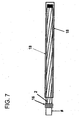
- a balloon may be micropleated by positioning the balloon to be packed or micropleated on a catheter shaft 14. Then, the balloon is heat set to the catheter shaft and a small diameter elastomeric tube 18, such as a silicone tube or other suitable material, is rolled over it (see Figure 7 ). The elastomeric tube is sealed via a balloon seal 16 at one end and inflated on the open end. The tube is inflated to an internal diameter which is greater than the desired outer diameter of the balloon when it is in final inflated form (see Figure 8 ). The heat set balloon is then inflated inside of the elastomeric tube 18. The elastomeric tube 18 is then deflated onto the inflated heat set balloon.
- a small diameter elastomeric tube 18 such as a silicone tube or other suitable material
- the elastomer in the elastomeric tube 18 in this stage applies a compressive radial force to the inflated balloon causing the balloon to deflate and creating micropleats in the balloon material 4.
- the elastomeric tube 18 is then removed from the heat set micropleated balloon.
- a material comprising a fluoropolymer and a second polymer is preferred.
- a common fluoropolymer appropriate for the fluoropolymer component is PTFE or expanded PTFE (ePTFE); however other fibrous reinforcing, highly-oriented materials such as polyolefins, polyesters, polyamides may be used.
- Polymers suitable for use as second polymers include but are not limited to elastomers such as urethanes, aromatic and aliphatic polyurethanes, thermoplastic polyurethanes, polyester thermoplastics, styrene block copolymers, and silicones.
- a second fluoropolymer, such as PTFE may be used for the second polymer.
- the above described methods enable the balloon profiles of the uninflated balloons to return to essentially the same profile after inflation and subsequent deflation.
- the same profile means that the size of the profile does not change by more than (30%) after deflation as compared to its profile prior to inflation.
- One composite film described comprises a porous reinforcing layer and a continuous polymer layer.
- the porous reinforcing polymer layer is preferably a thin, strong porous membrane that can be made in sheet form.
- the porous reinforcing polymer can be selected from a group of polymers including, but not limited to, olefin, PEEK, polyamide, polyurethane, polyester, polyethylene, and polytetrafluoroethylene.
- the porous reinforcing polymer is expanded polytetrafluoroethylene (ePTFE) may be made in accordance with the teachings of US Patent No. 5,476,589 or US Patent Application No. 11/334,243 to Bacino .
- the ePTFE membrane is anisotropic such that it is highly oriented in the one direction.
- An ePTFE membrane with a matrix tensile value in one direction of greater than 690 megapascals is preferred, and greater than 960 megapascals is even more preferred, and greater than 1,200 megapascals is most preferred.
- the exceptionally high matrix tensile value of ePTFE membrane allows the composite material to withstand very high hoop stress in the inflated balloon configuration.
- the high matrix tensile value of the ePTFE membrane makes it possible for example very thin layers to be used which reduces the deflated balloon profile. A small profile is necessary for the balloon to be able to be positioned in small arteries or veins or orifices.
- the balloon catheter In order for balloons to be positioned in some areas of the body, the balloon catheter must be able to move through a small bend radius, and a thinner walled tube is typically much more supple and capable of bending in this manner without creasing or causing damage to the wall of the vessel.
- the ePTFE membrane is relatively mechanically homogeneous.
- the mechanically balanced ePTFE membrane can increase the maximum hoop stress that the composite film made therefrom can withstand.
- the continuous polymer layer is coated onto at least one side of the porous reinforcing polymer.
- the continuous polymer layer is preferably an elastomer, such as, but not limited to, aromatic and aliphatic polyurethanes including copolymers, styrene block copolymers, silicones, preferably thermoplastic silicones, fluoro-silicones, fluoroelastomers, THV and latex.
- the continuous polymer layer is coated onto only one side of the porous reinforcing polymer.
- the continuous polymer layer is coated onto both sides of the porous reinforcing polymer.
- the continuous polymer layer is imbibed into the porous reinforcing polymer and the imbibed polymer fills the pores of the porous reinforcing polymer.
- the continuous polymer layer can be applied to the porous reinforcing polymer through any number of conventional methods including, but not limited to, lamination, transfer roll coating, wire-wound bar coating, reverse roll coating, and solution coating or solution imbibing.
- the continuous polymer layer is solution imbibed into the porous reinforcing polymer
- the continuous polymer layer is dissolved in a suitable solvent and coated onto and throughout the porous reinforcing polymer using a wire-wound rod process.
- the coated porous reinforcing polymer is then passed through a solvent oven and the solvent is removed leaving a continuous polymer layer coated onto and throughout the porous reinforcing polymer.
- the coated porous reinforcing polymer may not require the removal of solvent.
- the continuous polymer layer is coated onto at least one side of the porous reinforcing polymer and maintained in a "green" state where it can be subsequently cured.
- an ultraviolet light (UV) curable urethane may be used as the continuous polymer layer and coated onto the porous reinforcing polymer.
- the composite film comprising the porous reinforcing polymer and the UV curable urethane continuous polymer layer can then be wrapped to form at least one layer of the balloon and subsequently exposed to UV light and cured.
- a ply is a number of layers applied in a wrapping event.
- a layer is a single layer of composite film wrapped around the balloon.
- the balloon portion of a balloon catheter comprising micropleats distributed about the circumference of the balloon was made by inflating a 50 mm section of platinum cured silicone tubing (part # 30400, Saint-Gobain Performance Plastics, Taunton, MA) using a Balloon Development Station Model 210A (Beahm Designs, Campbell, CA) and a dispensing tip (part #: 5121-1-B, EFD, Inc., East Buffalo, RI). One end of the tube was attached to the dispensing tip with a touhy borst (part #: 80369, Qosina, Edgewood, NY). The silicone tube was inflated to approximately 275 kPa.
- the pressure was quickly lowered to about 130 kPa keeping the tube inflated.
- a 1.5 mm PTFE covered mandrel (New England Precision Grinding, Inc., Holliston, MA) was inserted into the tube approximately 100 mm.
- the tube was deflated and enough hand tension was applied to keep the length constant and under strain while it deflated and compressed onto the mandrel.
- the tube was cut rolled onto itself about 100 mm in length such that it formed a toroid and removed from the dispensing tip.
- the wrapped balloon of this example was comprised of balloon material laid in longitudinal passes about the lumen of the balloon.
- a longitudinal pass is comprised of one or more layers of material which are laid at similar angles in relation to the longitudinal axis of the balloon.
- a longitudinal pass comprises a distinctive layer or series of layers of material which are wound or wrapped to form a region or area distinct from surrounding or adjoining parts. It is important to note that a pass may span the entire length of the balloon or in certain instances, such as non-distending regions, the pass may span only a partial length of the balloon.
- a layer is considered to be one strand, strip or thickness of balloon material which may be wrapped, folded, laid or weaved over, around, beside or under another strand, strip or thickness of balloon material.
- a longitudinal pass may span the entire length of the balloon at a single wrap angle
- a longitudinal pass may also comprise a wrapping event in which the wrapping angles may be changed during the continuous longitudinal wrapping, so that in this type of wrapping pattern a single pass may include two or more wrap angles.
- the 4 mm diameter x 40 mm long balloon was mounted to a 0.36 mm diameter stainless steel hypotube (Creganna Medical Devices, Parkmore West Galway, Ireland) that had been helically wrapped with approximately three layers of an ePTFE/eFEP film composite as described.
- the balloon was attached and sealed to the catheter shaft by wrapping an approximately 5 mm wide ePTFE/eFEP film circumferentially around the balloon approximately five times.
- One band was wrapped on each end of the balloon and was centered over the end of the balloon and the catheter such that it made a seal by contacting both the hypotube shaft and the balloon.
- the rolled silicone tube with an approximately 20 mm long unrolled tail, was removed from the mandrel and then unrolled onto the fully deflated balloon mounted to the catheter shaft described above.
- the silicone tube was unrolled over the mounted composite balloon such that the end of the unrolled silicone tube protruded just beyond the end of the composite balloon and made a seal on the catheter shaft.
- the silicone tube was inflated through the tail using the dispensing tip and the Balloon Development Station Model 21 OA to about 130 kPa such that its inner diameter was approximately 4.5 mm.
- the balloon catheter was inflated to 4 mm diameter using approximately 130 kPa using a separate Balloon Development Station Model 210A and a touhy borst.
- the silicone tube was then fully deflated ensuring that there was no change in axial length of the tube.
- the balloon was deflated such that the silicone tube applied both a normal compressive force and a tangential shear force against the composite balloon. This shear force was exerted from the decreasing circumference of the inner diameter of the silicone tube and the surface friction between the two surfaces. These combined forces formed a multiplicity of evenly distributed longitudinal micropleats around the circumference of the balloon.
- the assembly was swaged, or radial compressed, using a heated swaging machine set to 550 kPa and 150°C for 30 seconds. The entire length of the balloon was swaged to heat set the micropleats. The silicone tube was then removed by inflating it to 130 kPa air pressure and unrolling it off of the balloon catheter. This process produced a balloon with tightly packed longitudinal micropleats attached and sealed to a catheter.
- a 4 mm balloon was folded in accordance with Example 1 above.
- the balloon was marked in an uninflated state with two parallel rows, each row having 11 linear marked points.
- the marked points on the first row were directly above and in line with corresponding marked points on the second row, so that the points lined up to form eleven columns.
- the marked points in each row radially expanded with the balloon wall and showed a relative equidistant spacing between adjacent marked points.
- the rows on the inflated balloon maintained the linear marked points in rows of analogous orientation to the initial marked rows on the uninflated balloon.
- the second row of linear marked points maintained linear rows of analogous orientation to the initial marked rows, and equidistant vertical spacing between the two parallel rows was observed analogous to the initial orientation of the marked points on the uninflated balloon. It was observed that the balloon inflated with radial concentric symmetry.
- a similar set of markings was conducted on a balloon described in Example 2, with four rows of 11 marked points each oriented to form parallel rows and columns.
- the marked points in each row radially expanded with the balloon wall and showed a relative equidistant spacing between adjacent marked points in the corresponding row.
- both the rows and columns of the inflated balloon maintained the linear marked points in analogous orientation to the initial marked rows on the uninflated balloon, again demonstrating radial symmetry upon inflation.
Description
- Catheter balloon designs have incorporated various methods with the intent of attaining a low catheter profile. A low catheter profile is desirable because it reduces the likelihood of catheter based complications. In addition, lower profiles allow use of the catheter in tortuous paths and therefore enable access to more parts of an anatomy, and allow use of smaller guide catheters. The previous approach to minimizing catheter profiles involves the use of materials which allow formation of thinner balloon walls which are subsequently folded and packed to achieve lower profiles. While such designs achieve relatively low catheter profiles, they fail to produce designs conducive to uniform stent deployment.
- Those balloon designs that have achieved greater uniformity in stent deployment generally exhibit multiple folds, also known as "wings" or "pleats". Packing designs known in the art include tri-folded balloon profiles and other multiple canted wing profiles. These packing designs are not known to achieve a uniform expansion when used in stenosis dilation procedures, thus increasing the likelihood of contributing to arterial trauma. Also, non-uniform stent deployment leads to non-uniform stent cell size per area, which may lead to tissue and/or plaque prolapse, which in turn results in a smaller luminal area for blood flow.
-
US 6,013,092 relates to methods for folding a catheter mounted balloon. The methods generally comprise folding a balloon portion that is in a flattened configuration at least twice, in opposite directions, so that any rotational forces created by the unfolding of the balloon as it is inflated will counteract each other. Catheter balloons having longitudinal furrows; and catheters and systems for implanting endoluminal devices with such balloons are also disclosed. -
US 2002/0163104 relates to an apparatus for folding a catheter balloon in two steps. In the first step the balloon is folded into a shape with curved wings and angled wing bases (a spiral-pleated shape) and in the second step the balloon is folded tightly round the shaft by means of radial compression through a diameter reduction. -
US 5,308,356 relates to a passive perfusion angioplasty catheter which defines at least one passage between a surface of the balloon and the interior wall of an artery to permit blood flow therethrough when the balloon member is pressed against the artery wall. Examples of pleated balloon members, which provide the passage for blood flow are described and illustrated. -
US 2003/0131716 relates to a non-compliant balloon with compliant top layer to protect coated stents during expansion. In the uninflated/deflated state the balloon comprises longitudinal wings, which wrap around the longitudinal axis of the non-compliant balloon. -
EP 0 737 488 relates to a balloon catheter with a lobated balloon. The expandable balloon member comprises a number of relatively stiff sections extending on a small diameter in a longitudinal direction of the basic body and relatively pliable sections extending in between wherein the relatively pliable sections form lobes in an expanded state of the balloon member. -
US 5,893,840 relates to a balloon catheter which comprises microcapsules of a drug on its surface. In some embodiments, these microcapsules are held in place mechanically by folds in the balloon. As the balloon inflates, the folds are eliminated which expels the microcapsules into the treatment site. - (
US 6,010,480 ) relates to an expansible balloon cathether which may be compacted by pleating about a central tube. As the balloon is expanded, the pleats open into a generally circular configuration. - See as well
US 5 147 302 andWO 9511718 - What is needed is a flexible catheter balloon packing design which facilitates radial symmetry about the circumference of the balloon during inflation in vivo so as to provide a smaller introducer sheath so as to reduce potential trauma to the access site during introduction and to the arterial walls during inflation or device deployment. Prevention of plaque prolapse through stent cells post deployment is also desired. The present invention solves this long felt need and contributes to uniform stent deployment.
- The present invention provides a method of forming the micropleats on a balloon according to claim 1.
- The examples provides a catheter balloon formed of at least one balloon material having a longitudinal axis with micropleats distributed about the circumference of the balloon resulting in a low profile and an essential symmetry upon inflation. The balloon of the examples is able to achieve a low profile due to smaller introducer sheath requirements. Additionally, the balloon reduces vessel trauma through radial concentric inflation of the balloon itself.
-
-
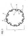
Figure 1 shows a cross section of an uninflated micropleated balloon. -
Figure 2 shows a cross section of an uninflated folded balloon which embodies features of the prior art. -
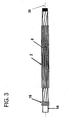
Figure 3 shows an uninflated micropleated catheter balloon. -
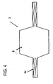
Figure 4 shows a side view of an inflated micropleated catheter balloon. -
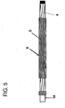
Figure 5 shows a top view of a deflated micropleated catheter balloon. -
Figure 6 shows a schematic of a micropleated balloon affixed to a catheter shaft. -
Figure 7 shows a deflated elastomer cover on a non-inflated balloon which is not yet micropleated. -
Figure 8 shows a deflated elastomer tube covering an inflated balloon which is not yet micropleated. - There are described examples of providing a catheter balloon with the balloon material formed into micropleats distributed about the circumference of the balloon. The micropleats reduce the entry profile of the balloon and are formed to pull taut in an inflated state.
- As shown in
Figure 1 , thecatheter balloon 2 is formed of at least oneballoon material 4. The balloon material is formed into a balloon having a longitudinal axis andmicropleats 8 formed into the balloon. Balloon pleat size and distribution is a function of the inflated diameter, non-inflated diameter and the thickness of the balloon material. - The
micropleats 8 are invaginated areas of foldedballoon material 4 with at least onefold 5 or bend which forms apocket 10 of balloon material. The pocket comprises an opening 11 and at least one side of the pocket and abottom 12 of thepocket 10. The inside of the pocket is a cavity wherein the most distant part of the pocket is adjacent to the bottom of the pocket. Theside 13 of the pocket runs from the balloon opening to the bottom of the pocket flanking the opening to the pocket. The opening 11 is ideally located opposite of thebottom 12 of the pocket. Themicropleats 8 are distributed about the circumference of the balloon. The bottom of each micropleat pocket is oriented such that it is free of contact or overlap with any other portion of an adjacent micropleat. Each micropleat has at least onefold 5 which allows balloon material to be stored upon itself. While the micropleats are depicted as running longitudinally in the direction of the axis, helical orientations, S-shaped orientations and other configurations of micropleat distribution may be formed. In one example, as shown inFigure 1 , the material is folded upon itself to form at least one pocket so that at least 50% of the pocket bottoms are located on the inside of the balloon juxtaposed to the balloon lumen in an uninflated state. In a more preferred example at least 75% of the pocket bottoms are located on the inside of the balloon juxtaposed to the balloon lumen. In a most preferred example, at least 90% of the pocket bottoms are located on the inside of the balloon juxtaposed to the balloon lumen. The catheter balloon has a longitudinal axis with an inner lumen and at least one balloon material forming an outer circumference and at least one micropleat. The micropleat comprises a pocket of balloon material having an opening commencing at the lumen, a bottom and sides where each side folds upon itself to connect the bottom of the pocket to the opening. The micropleat reduces profile and stores the balloon material in a folded configuration until inflation. The micropleats are formed to pull taut in an inflated state. Upon inflation pressure, the balloon exhibits essentially radially symmetric inflation and imparts an equal hydrostatic load during clinical use. Radially symmetric inflation is exhibited when a balloon in an uninflated state can be shown to expand with inflation pressure in a manner allowing points on the balloon to maintain proportionate spacing with each other in the inflated state. When the balloon is used with a stent, the radial inflation symmetry of the balloon also contributes to uniform stent deployment. Such uniform radial inflation has been found to reduce trauma to the vessels into which the balloon is deployed. -
Figure 2 shows a cross section of a traditional folded balloon design, As can be seen, the material is folded upon itself with long folds wrapped around thelumen 6 of the balloon. In this folding pattern, the folds overlap adjacent folds of the balloon around thelumen 6. Internal inflation pressure enters the opening to the pocket and then fills the cavities prior to the pocket sides shortening, thus causing a non-symmetric inflation. As seen inFigure 1 , the short walls of the micropleats grow circumferentially upon the addition of an inflation pressure, allowing a symmetrical inflation. The micropleats are symmetric and uniform in their distribution. The micropleats may be oriented in different ways. In one example, as shown inFigure 3 , themicropleats 8 are oriented longitudinally, i.e. substantially parallel to thelongitudinal axis 20 of the catheter over the working length of theballoon 2. The longitudinal micropleats are evenly distributed about the circumference of the balloon diameter. Aballoon seal 16 may be present, distinct from the inflatable balloon portion, if desired, on thecatheter shaft 14. The number of micropleats in the balloon may vary, but should be at least six pleats or greater. In a preferred example, the balloon diameter is 1.0 mm or less. However, the micropleats may be utilized on any size balloon. In an inflated state as shown inFigure 4 , themicropleats 8 of the balloon pull taut such that they are not visible. The micropleats may be arranged on a formedballoon 2 or on a tubular structure of balloon material. - Multiple methods may be used in micropleating a balloon. As shown in
Figure 5 , an uninflated balloon may be adhered to acatheter shaft 14 and then inflated to achieve an inflated outer diameter. A compressive radial force is then applied to the inflated outer diameter of the balloon to cause deflation of the balloon and create longitudinal folds in theballoon material 4. To set thefolds 5 of themicropleats 8 in place, heat, along with a compressive force, is applied so that the balloon maintains its micropleated structure (seeFigure 6 ). In general, the number of pleats generally increases as the ratio of inflated balloon diameter to deflated/packed balloon diameter increases. Aballoon seal 16 is shown for reference. An increase in pleats is also observed as the thickness of the balloon wall decreases. - In one aspect, the average micropleat width is less than 1 mm, preferably less than 0.7 mm, independent of inflated/diameter balloon diameters.
- A balloon may be micropleated by positioning the balloon to be packed or micropleated on a
catheter shaft 14. Then, the balloon is heat set to the catheter shaft and a small diameterelastomeric tube 18, such as a silicone tube or other suitable material, is rolled over it (seeFigure 7 ). The elastomeric tube is sealed via aballoon seal 16 at one end and inflated on the open end. The tube is inflated to an internal diameter which is greater than the desired outer diameter of the balloon when it is in final inflated form (seeFigure 8 ). The heat set balloon is then inflated inside of theelastomeric tube 18. Theelastomeric tube 18 is then deflated onto the inflated heat set balloon. The elastomer in theelastomeric tube 18 in this stage applies a compressive radial force to the inflated balloon causing the balloon to deflate and creating micropleats in theballoon material 4. Theelastomeric tube 18 is then removed from the heat set micropleated balloon. - Of the types of balloon material suitable, a material comprising a fluoropolymer and a second polymer is preferred. A common fluoropolymer appropriate for the fluoropolymer component is PTFE or expanded PTFE (ePTFE); however other fibrous reinforcing, highly-oriented materials such as polyolefins, polyesters, polyamides may be used. Polymers suitable for use as second polymers include but are not limited to elastomers such as urethanes, aromatic and aliphatic polyurethanes, thermoplastic polyurethanes, polyester thermoplastics, styrene block copolymers, and silicones. Alternatively, a second fluoropolymer, such as PTFE, may be used for the second polymer. The above described methods enable the balloon profiles of the uninflated balloons to return to essentially the same profile after inflation and subsequent deflation. Essentially, the same profile means that the size of the profile does not change by more than (30%) after deflation as compared to its profile prior to inflation.
- One composite film described comprises a porous reinforcing layer and a continuous polymer layer. The porous reinforcing polymer layer is preferably a thin, strong porous membrane that can be made in sheet form. The porous reinforcing polymer can be selected from a group of polymers including, but not limited to, olefin, PEEK, polyamide, polyurethane, polyester, polyethylene, and polytetrafluoroethylene. In a preferred embodiment, the porous reinforcing polymer is expanded polytetrafluoroethylene (ePTFE) may be made in accordance with the teachings of
US Patent No. 5,476,589 orUS Patent Application No. 11/334,243 to Bacino - In another preferred example, the ePTFE membrane is relatively mechanically homogeneous. The mechanically balanced ePTFE membrane can increase the maximum hoop stress that the composite film made therefrom can withstand.
- The continuous polymer layer is coated onto at least one side of the porous reinforcing polymer. The continuous polymer layer is preferably an elastomer, such as, but not limited to, aromatic and aliphatic polyurethanes including copolymers, styrene block copolymers, silicones, preferably thermoplastic silicones, fluoro-silicones, fluoroelastomers, THV and latex. In one example, the continuous polymer layer is coated onto only one side of the porous reinforcing polymer. The continuous polymer layer is coated onto both sides of the porous reinforcing polymer. In a preferred example, the continuous polymer layer is imbibed into the porous reinforcing polymer and the imbibed polymer fills the pores of the porous reinforcing polymer. The continuous polymer layer can be applied to the porous reinforcing polymer through any number of conventional methods including, but not limited to, lamination, transfer roll coating, wire-wound bar coating, reverse roll coating, and solution coating or solution imbibing. In a preferred example, the continuous polymer layer is solution imbibed into the porous reinforcing polymer In this example, the continuous polymer layer is dissolved in a suitable solvent and coated onto and throughout the porous reinforcing polymer using a wire-wound rod process. The coated porous reinforcing polymer is then passed through a solvent oven and the solvent is removed leaving a continuous polymer layer coated onto and throughout the porous reinforcing polymer. In some cases, such as when silicone is used as the continuous polymer layer, the coated porous reinforcing polymer may not require the removal of solvent. In another example, the continuous polymer layer is coated onto at least one side of the porous reinforcing polymer and maintained in a "green" state where it can be subsequently cured. For example, an ultraviolet light (UV) curable urethane may be used as the continuous polymer layer and coated onto the porous reinforcing polymer. The composite film comprising the porous reinforcing polymer and the UV curable urethane continuous polymer layer can then be wrapped to form at least one layer of the balloon and subsequently exposed to UV light and cured. A ply is a number of layers applied in a wrapping event. A layer is a single layer of composite film wrapped around the balloon.
- While particular embodiments of the present invention have been illustrated and described herein, the present invention should not be limited to such illustrations and descriptions. It should be apparent that changes and modifications may be incorporated and embodied as part of the present invention within the scope of the following claims.
- The following examples are intended to be illustrative . These examples are in no way intended to limit the present invention..
- The balloon portion of a balloon catheter comprising micropleats distributed about the circumference of the balloon was made by inflating a 50 mm section of platinum cured silicone tubing (part # 30400, Saint-Gobain Performance Plastics, Taunton, MA) using a Balloon Development Station Model 210A (Beahm Designs, Campbell, CA) and a dispensing tip (part #: 5121-1-B, EFD, Inc., East Providence, RI). One end of the tube was attached to the dispensing tip with a touhy borst (part #: 80369, Qosina, Edgewood, NY). The silicone tube was inflated to approximately 275 kPa. Once fully inflated, the pressure was quickly lowered to about 130 kPa keeping the tube inflated. While the silicone tube was still inflated, a 1.5 mm PTFE covered mandrel (New England Precision Grinding, Inc., Holliston, MA) was inserted into the tube approximately 100 mm. The tube was deflated and enough hand tension was applied to keep the length constant and under strain while it deflated and compressed onto the mandrel. The tube was cut rolled onto itself about 100 mm in length such that it formed a toroid and removed from the dispensing tip.
- The wrapped balloon of this example was comprised of balloon material laid in longitudinal passes about the lumen of the balloon. A longitudinal pass is comprised of one or more layers of material which are laid at similar angles in relation to the longitudinal axis of the balloon. A longitudinal pass comprises a distinctive layer or series of layers of material which are wound or wrapped to form a region or area distinct from surrounding or adjoining parts. It is important to note that a pass may span the entire length of the balloon or in certain instances, such as non-distending regions, the pass may span only a partial length of the balloon.
- A layer is considered to be one strand, strip or thickness of balloon material which may be wrapped, folded, laid or weaved over, around, beside or under another strand, strip or thickness of balloon material.
- While it is clear that a longitudinal pass may span the entire length of the balloon at a single wrap angle, a longitudinal pass may also comprise a wrapping event in which the wrapping angles may be changed during the continuous longitudinal wrapping, so that in this type of wrapping pattern a single pass may include two or more wrap angles.
- The 4 mm diameter x 40 mm long balloon was mounted to a 0.36 mm diameter stainless steel hypotube (Creganna Medical Devices, Parkmore West Galway, Ireland) that had been helically wrapped with approximately three layers of an ePTFE/eFEP film composite as described. The balloon was attached and sealed to the catheter shaft by wrapping an approximately 5 mm wide ePTFE/eFEP film circumferentially around the balloon approximately five times. One band was wrapped on each end of the balloon and was centered over the end of the balloon and the catheter such that it made a seal by contacting both the hypotube shaft and the balloon.
- The rolled silicone tube, with an approximately 20 mm long unrolled tail, was removed from the mandrel and then unrolled onto the fully deflated balloon mounted to the catheter shaft described above. The silicone tube was unrolled over the mounted composite balloon such that the end of the unrolled silicone tube protruded just beyond the end of the composite balloon and made a seal on the catheter shaft. The silicone tube was inflated through the tail using the dispensing tip and the Balloon Development Station Model 21 OA to about 130 kPa such that its inner diameter was approximately 4.5 mm. Once the silicone tube was fully inflated, the balloon catheter was inflated to 4 mm diameter using approximately 130 kPa using a separate Balloon Development Station Model 210A and a touhy borst.
- The silicone tube was then fully deflated ensuring that there was no change in axial length of the tube. With the axial length of the silicone tube fixed, the balloon was deflated such that the silicone tube applied both a normal compressive force and a tangential shear force against the composite balloon. This shear force was exerted from the decreasing circumference of the inner diameter of the silicone tube and the surface friction between the two surfaces. These combined forces formed a multiplicity of evenly distributed longitudinal micropleats around the circumference of the balloon.
- After disconnecting both the balloon catheter and the silicone tube from the inflation devices, the assembly was swaged, or radial compressed, using a heated swaging machine set to 550 kPa and 150°C for 30 seconds. The entire length of the balloon was swaged to heat set the micropleats. The silicone tube was then removed by inflating it to 130 kPa air pressure and unrolling it off of the balloon catheter. This process produced a balloon with tightly packed longitudinal micropleats attached and sealed to a catheter.
- A 4 mm balloon was folded in accordance with Example 1 above. The balloon was marked in an uninflated state with two parallel rows, each row having 11 linear marked points. The marked points on the first row were directly above and in line with corresponding marked points on the second row, so that the points lined up to form eleven columns. Upon inflation pressure, the marked points in each row radially expanded with the balloon wall and showed a relative equidistant spacing between adjacent marked points. Thus, the rows on the inflated balloon maintained the linear marked points in rows of analogous orientation to the initial marked rows on the uninflated balloon. Additionally, the second row of linear marked points maintained linear rows of analogous orientation to the initial marked rows, and equidistant vertical spacing between the two parallel rows was observed analogous to the initial orientation of the marked points on the uninflated balloon. It was observed that the balloon inflated with radial concentric symmetry.
- A similar set of markings was conducted on a balloon described in Example 2, with four rows of 11 marked points each oriented to form parallel rows and columns. Upon inflation pressure, the marked points in each row radially expanded with the balloon wall and showed a relative equidistant spacing between adjacent marked points in the corresponding row. Similarly, the columns, radially expanded with the balloon wall and showed a relative equidistant spacing between adjacent marked points in the corresponding columns, and maintained a parallel orientation between the columns and the rows. Thus, both the rows and columns of the inflated balloon maintained the linear marked points in analogous orientation to the initial marked rows on the uninflated balloon, again demonstrating radial symmetry upon inflation.
Claims (6)
- A method of micropleating a balloon (2) comprising:a. heat setting the balloon (2);b. rolling a small diameter elastomeric tube (18) over the heat set balloon (2);c. sealing the elastomeric tube (18) on one end;d. inflating the elastomeric tube (18) on the open end;e. achieving inflation of the tube (18) to an internal diameter which is greater than the desired outer diameter of the inflated heat set balloon (2);f. inflating the heat set balloon (2);g. deflating the elastomeric tube (18);h. deflating the heat set balloon (2) thus creating axial folds;i. applying heat and compressive force to set the axial folds, wherein said folds define micropleats (8), where each micropleat (8) comprises a pocket (10) of balloon material (4) having an opening (11) commencing at the outer circumference of the balloon (2), a bottom (12) adjacent the lumen and two sides (13) where each side (13) folds (5) upon itself towards the bottom (12) of the pocket (10) to position the opening (11) of the pocket (10) adjacent the bottom (12) of the pocket (10) andj. removing the elastomeric tube (18) from over the heat set micropleated balloon (2).
- The method of claim 1, wherein the elastomeric tube (18) is silicone.
- The method of claim 1, wherein the balloon (2) is comprised of a fluoropolymer and a polymer.
- The method of claim 3, wherein the polymer is selected from one or more of the following groups:an elastomer;a urethane;a second fluoropolymer.
- The method of claim 4, wherein the fluoropolymer is PTFE.
- The method of any one of claims 1 to 5, wherein:the folds of step (i) are essentially S-shaped; and/or
the balloon (2) profile in the uninflated state is essentially the same as the balloon (2) profile in a deflated state.
Applications Claiming Priority (2)
| Application Number | Priority Date | Filing Date | Title |
|---|---|---|---|
| US11/500,793 US20080097300A1 (en) | 2006-08-07 | 2006-08-07 | Catheter balloon with multiple micropleats |
| PCT/US2007/017307 WO2008021019A2 (en) | 2006-08-07 | 2007-08-02 | Catheter balloon with multiple micropleats |
Publications (2)
| Publication Number | Publication Date |
|---|---|
| EP2049182A2 EP2049182A2 (en) | 2009-04-22 |
| EP2049182B1 true EP2049182B1 (en) | 2014-11-26 |
Family
ID=39082531
Family Applications (1)
| Application Number | Title | Priority Date | Filing Date |
|---|---|---|---|
| EP07836458.5A Active EP2049182B1 (en) | 2006-08-07 | 2007-08-02 | Method of micropleating a catheter balloon with multiple micropleats |
Country Status (7)
| Country | Link |
|---|---|
| US (1) | US20080097300A1 (en) |
| EP (1) | EP2049182B1 (en) |
| JP (1) | JP5694662B2 (en) |
| AU (1) | AU2007284917B2 (en) |
| CA (1) | CA2660017C (en) |
| ES (1) | ES2528364T3 (en) |
| WO (1) | WO2008021019A2 (en) |
Cited By (1)
| Publication number | Priority date | Publication date | Assignee | Title |
|---|---|---|---|---|
| CN106166324A (en) * | 2016-06-27 | 2016-11-30 | 南京双威生物医学科技有限公司 | A kind of biocompatibility dilator |
Families Citing this family (23)
| Publication number | Priority date | Publication date | Assignee | Title |
|---|---|---|---|---|
| US8177743B2 (en) | 1998-05-18 | 2012-05-15 | Boston Scientific Scimed, Inc. | Localized delivery of drug agents |
| WO2008095052A2 (en) | 2007-01-30 | 2008-08-07 | Loma Vista Medical, Inc., | Biological navigation device |
| US8109904B1 (en) * | 2007-06-25 | 2012-02-07 | Abbott Cardiovascular Systems Inc. | Drug delivery medical devices |
| US20090227948A1 (en) * | 2008-03-06 | 2009-09-10 | Boston Scientific Scimed, Inc. | Balloon catheter devices with sheath covering |
| EP2285443B1 (en) | 2008-05-01 | 2016-11-23 | Bayer Intellectual Property GmbH | Catheter balloon drug adherence techniques and methods |
| WO2009149108A1 (en) | 2008-06-02 | 2009-12-10 | Loma Vista Medical, Inc. | Inflatable medical devices |
| EP2147695B1 (en) * | 2008-07-23 | 2011-11-30 | Abbott Laboratories Vascular Enterprises Limited | Balloon of a balloon catheter |
| WO2012009486A2 (en) | 2010-07-13 | 2012-01-19 | Loma Vista Medical, Inc. | Inflatable medical devices |
| US10188436B2 (en) | 2010-11-09 | 2019-01-29 | Loma Vista Medical, Inc. | Inflatable medical devices |
| US20140276608A1 (en) * | 2013-03-13 | 2014-09-18 | Abbott Cardiovascular Systems, Inc. | Balloon sclerotherapy |
| US9770352B2 (en) * | 2013-03-14 | 2017-09-26 | W. L. Gore & Associates, Inc. | Inflatable balloon and cover |
| US10953193B2 (en) | 2013-07-16 | 2021-03-23 | Covidien Lp | Microcatheter with modified PTFE liner |
| EP3270997B1 (en) | 2015-03-19 | 2019-07-03 | Prytime Medical Devices, Inc. | System for low-profile occlusion balloon catheter |
| KR101755250B1 (en) * | 2015-10-27 | 2017-07-07 | (주)인투케어 | Balloon catheter and device for surgical procedures including the same |
| CA3012017A1 (en) | 2016-06-02 | 2017-12-07 | Prytime Medical Devices, Inc. | System and method for low-profile occlusion balloon catheter |
| JP6955556B2 (en) * | 2016-09-30 | 2021-10-27 | サーモディクス,インコーポレイテッド | Therapeutic balloon system with contraction guide |
| JP6928111B2 (en) | 2017-01-12 | 2021-09-01 | ザ リージェンツ オブ ザ ユニバーシティ オブ カリフォルニアThe Regents Of The University Of California | Increased intravascular perfusion for critical care center |
| GB2558930A (en) * | 2017-01-20 | 2018-07-25 | The Flume Catheter Company Ltd | Urinary catheter |
| WO2018195507A1 (en) | 2017-04-21 | 2018-10-25 | The Regents Of The University Of California | Aortic flow meter and pump for partial-aortic occlusion |
| WO2020033372A1 (en) * | 2018-08-06 | 2020-02-13 | Prytime Medical Devices, Inc. | System and method for low profile occlusion balloon catheter |
| CN110420375B (en) * | 2019-06-27 | 2022-09-02 | 先健科技(深圳)有限公司 | Balloon catheter and manufacturing method thereof |
| JP2023502022A (en) * | 2019-11-12 | 2023-01-20 | マイクロベンション インコーポレイテッド | Balloon catheter with enhanced characteristics |
| EP4121159A2 (en) | 2020-03-16 | 2023-01-25 | Certus Critical Care, Inc. | Blood flow control devices, systems, and methods and error detection thereof |
Citations (2)
| Publication number | Priority date | Publication date | Assignee | Title |
|---|---|---|---|---|
| US5893840A (en) * | 1991-01-04 | 1999-04-13 | Medtronic, Inc. | Releasable microcapsules on balloon catheters |
| US6010480A (en) * | 1993-08-23 | 2000-01-04 | Boston Scientific Corporation | Balloon catheter |
Family Cites Families (94)
| Publication number | Priority date | Publication date | Assignee | Title |
|---|---|---|---|---|
| US3634924A (en) * | 1970-04-20 | 1972-01-18 | American Hospital Supply Corp | Method of making multilumen balloon catheter |
| SE392582B (en) * | 1970-05-21 | 1977-04-04 | Gore & Ass | PROCEDURE FOR THE PREPARATION OF A POROST MATERIAL, BY EXPANDING AND STRETCHING A TETRAFLUORETENE POLYMER PREPARED IN AN PASTE-FORMING EXTENSION PROCEDURE |
| US3640282A (en) * | 1970-08-06 | 1972-02-08 | Jack M Kamen | Tracheal tube with normally expanded balloon cuff |
| US4003382A (en) * | 1975-07-25 | 1977-01-18 | Ethicon, Inc. | Retention catheter and method of manufacture |
| US4280500A (en) * | 1978-03-31 | 1981-07-28 | Kazuaki Ono | Tubular flexible medical instrument |
| US4194041A (en) * | 1978-06-29 | 1980-03-18 | W. L. Gore & Associates, Inc. | Waterproof laminate |
| JPS5582884A (en) * | 1978-12-19 | 1980-06-21 | Olympus Optical Co | Flexible tube and its manufacture |
| US4327736A (en) * | 1979-11-20 | 1982-05-04 | Kanji Inoue | Balloon catheter |
| US4338942A (en) * | 1980-10-20 | 1982-07-13 | Fogarty Thomas J | Dilatation catherter apparatus |
| US4596839A (en) * | 1981-09-16 | 1986-06-24 | Peters William E | Elastomer PTFE composition |
| DE3235974A1 (en) * | 1981-11-24 | 1983-06-01 | Volkmar Dipl.-Ing. Merkel (FH), 8520 Erlangen | DEVICE FOR REMOVAL OR FOR THE EXPANSION OF CONSTRAINTS IN BODY LIQUID LEADING VESSELS |
| US4443511A (en) * | 1982-11-19 | 1984-04-17 | W. L. Gore & Associates, Inc. | Elastomeric waterproof laminate |
| US4637396A (en) * | 1984-10-26 | 1987-01-20 | Cook, Incorporated | Balloon catheter |
| US4737219A (en) * | 1985-02-12 | 1988-04-12 | Becton, Dickinson And Company | Method for bonding polyurethane balloons to multilumen catheters |
| US4650466A (en) * | 1985-11-01 | 1987-03-17 | Angiobrade Partners | Angioplasty device |
| US4733665C2 (en) * | 1985-11-07 | 2002-01-29 | Expandable Grafts Partnership | Expandable intraluminal graft and method and apparatus for implanting an expandable intraluminal graft |
| JPS62236560A (en) * | 1986-04-09 | 1987-10-16 | テルモ株式会社 | Catheter for repairing blood vessel |
| US4743480A (en) * | 1986-11-13 | 1988-05-10 | W. L. Gore & Associates, Inc. | Apparatus and method for extruding and expanding polytetrafluoroethylene tubing and the products produced thereby |
| US4816339A (en) * | 1987-04-28 | 1989-03-28 | Baxter International Inc. | Multi-layered poly(tetrafluoroethylene)/elastomer materials useful for in vivo implantation |
| US4819751A (en) * | 1987-10-16 | 1989-04-11 | Baxter Travenol Laboratories, Inc. | Valvuloplasty catheter and method |
| US5499980A (en) * | 1988-08-08 | 1996-03-19 | Scimed Life Systems, Inc. | Polyimide balloon catheter and method of making same |
| US5192296A (en) * | 1988-08-31 | 1993-03-09 | Meadox Medicals, Inc. | Dilatation catheter |
| US4896669A (en) * | 1988-08-31 | 1990-01-30 | Meadox Medicals, Inc. | Dilatation catheter |
| CA1329091C (en) * | 1989-01-31 | 1994-05-03 | Geoffrey S. Martin | Catheter with balloon retainer |
| US5087244A (en) * | 1989-01-31 | 1992-02-11 | C. R. Bard, Inc. | Catheter and method for locally applying medication to the wall of a blood vessel or other body lumen |
| US5112304A (en) * | 1989-03-17 | 1992-05-12 | Angeion Corporation | Balloon catheter |
| US5147302A (en) * | 1989-04-21 | 1992-09-15 | Scimed Life Systems, Inc. | Method of shaping a balloon of a balloon catheter |
| US5100429A (en) * | 1989-04-28 | 1992-03-31 | C. R. Bard, Inc. | Endovascular stent and delivery system |
| JP2545981B2 (en) * | 1989-05-09 | 1996-10-23 | 東レ株式会社 | Balloon catheter |
| FR2647813B1 (en) * | 1989-06-01 | 1991-09-20 | Ugine Aciers | MAGNETIC SHEET OBTAINED FROM A HOT-ROLLED STEEL STRIP CONTAINING PARTICULARLY IRON, SILICON AND ALUMINUM |
| US5116318A (en) * | 1989-06-06 | 1992-05-26 | Cordis Corporation | Dilatation balloon within an elastic sleeve |
| US5108370A (en) * | 1989-10-03 | 1992-04-28 | Paul Walinsky | Perfusion balloon catheter |
| US5290306A (en) * | 1989-11-29 | 1994-03-01 | Cordis Corporation | Puncture resistant balloon catheter |
| US5478320A (en) * | 1989-11-29 | 1995-12-26 | Cordis Corporation | Puncture resistant balloon catheter and method of manufacturing |
| DE4018525C2 (en) * | 1990-06-09 | 1994-05-05 | Kaltenbach Martin | Expandable area catheter |
| US5498238A (en) * | 1990-06-15 | 1996-03-12 | Cortrak Medical, Inc. | Simultaneous angioplasty and phoretic drug delivery |
| AU8074591A (en) * | 1990-06-15 | 1992-01-07 | Cortrak Medical, Inc. | Drug delivery apparatus and method |
| US5195970A (en) * | 1991-04-26 | 1993-03-23 | Gahara William J | Collapsible balloon catheters |
| US5197978B1 (en) * | 1991-04-26 | 1996-05-28 | Advanced Coronary Tech | Removable heat-recoverable tissue supporting device |
| US5213576A (en) * | 1991-06-11 | 1993-05-25 | Cordis Corporation | Therapeutic porous balloon catheter |
| CA2074304C (en) * | 1991-08-02 | 1996-11-26 | Cyril J. Schweich, Jr. | Drug delivery catheter |
| JPH05192408A (en) * | 1991-09-06 | 1993-08-03 | C R Bard Inc | Production of expansion balloon |
| US5304214A (en) * | 1992-01-21 | 1994-04-19 | Med Institute, Inc. | Transurethral ablation catheter |
| US5304120A (en) * | 1992-07-01 | 1994-04-19 | Btx Inc. | Electroporation method and apparatus for insertion of drugs and genes into endothelial cells |
| US5348538A (en) * | 1992-09-29 | 1994-09-20 | Scimed Life Systems, Inc. | Shrinking balloon catheter having nonlinear or hybrid compliance curve |
| US5500180A (en) * | 1992-09-30 | 1996-03-19 | C. R. Bard, Inc. | Method of making a distensible dilatation balloon using a block copolymer |
| US5512051A (en) * | 1993-02-16 | 1996-04-30 | Boston Scientific Corporation | Slip-layered catheter balloon |
| US5308356A (en) * | 1993-02-25 | 1994-05-03 | Blackshear Jr Perry L | Passive perfusion angioplasty catheter |
| JP3345786B2 (en) * | 1993-03-17 | 2002-11-18 | ジャパンゴアテックス株式会社 | Flexible tube and method of manufacturing the same |
| US6027779A (en) * | 1993-08-18 | 2000-02-22 | W. L. Gore & Associates, Inc. | Thin-wall polytetrafluoroethylene tube |
| US5409495A (en) * | 1993-08-24 | 1995-04-25 | Advanced Cardiovascular Systems, Inc. | Apparatus for uniformly implanting a stent |
| GB2281865B (en) * | 1993-09-16 | 1997-07-30 | Cordis Corp | Endoprosthesis having multiple laser welded junctions,method and procedure |
| WO1996014895A1 (en) * | 1994-11-14 | 1996-05-23 | Scimed Life Systems, Inc. | Catheter balloon with retraction coating |
| US5496276A (en) * | 1993-09-20 | 1996-03-05 | Scimed Life Systems, Inc. | Catheter balloon with retraction coating |
| US5425710A (en) * | 1993-10-26 | 1995-06-20 | Medtronic, Inc. | Coated sleeve for wrapping dilatation catheter balloons |
| US5484411A (en) * | 1994-01-14 | 1996-01-16 | Cordis Corporation | Spiral shaped perfusion balloon and method of use and manufacture |
| US5415636A (en) * | 1994-04-13 | 1995-05-16 | Schneider (Usa) Inc | Dilation-drug delivery catheter |
| US5499995C1 (en) * | 1994-05-25 | 2002-03-12 | Paul S Teirstein | Body passageway closure apparatus and method of use |
| US5609605A (en) * | 1994-08-25 | 1997-03-11 | Ethicon, Inc. | Combination arterial stent |
| US5499973A (en) * | 1994-09-08 | 1996-03-19 | Saab; Mark A. | Variable stiffness balloon dilatation catheters |
| US5519172A (en) * | 1994-09-13 | 1996-05-21 | W. L. Gore & Associates, Inc. | Jacket material for protection of electrical conductors |
| US5527282A (en) * | 1994-12-09 | 1996-06-18 | Segal; Jerome | Vascular dilatation device and method |
| NL1000106C2 (en) * | 1995-04-10 | 1996-10-11 | Cordis Europ | Balloon balloon balloon catheter and method of making the balloon. |
| US5641373A (en) * | 1995-04-17 | 1997-06-24 | Baxter International Inc. | Method of manufacturing a radially-enlargeable PTFE tape-reinforced vascular graft |
| US5766201A (en) * | 1995-06-07 | 1998-06-16 | Boston Scientific Corporation | Expandable catheter |
| US20060271091A1 (en) * | 1995-09-18 | 2006-11-30 | Campbell Carey V | Balloon catheter device |
| US5868704A (en) * | 1995-09-18 | 1999-02-09 | W. L. Gore & Associates, Inc. | Balloon catheter device |
| US5752934A (en) * | 1995-09-18 | 1998-05-19 | W. L. Gore & Associates, Inc. | Balloon catheter device |
| US5908406A (en) * | 1996-01-31 | 1999-06-01 | E. I. Du Pont De Nemours And Company | Dilatation catheter balloons with improved puncture resistance |
| US6746425B1 (en) * | 1996-06-14 | 2004-06-08 | Futuremed Interventional | Medical balloon |
| US5868708A (en) * | 1997-05-07 | 1999-02-09 | Applied Medical Resources Corporation | Balloon catheter apparatus and method |
| US6234995B1 (en) * | 1998-11-12 | 2001-05-22 | Advanced Interventional Technologies, Inc. | Apparatus and method for selectively isolating a proximal anastomosis site from blood in an aorta |
| US6013092A (en) * | 1998-08-18 | 2000-01-11 | Baxter International Inc. | Folding of catheter-mounted balloons to facilitate non-rotational radial expansion of intraluminal devices |
| US6336937B1 (en) * | 1998-12-09 | 2002-01-08 | Gore Enterprise Holdings, Inc. | Multi-stage expandable stent-graft |
| US6905743B1 (en) * | 1999-02-25 | 2005-06-14 | Boston Scientific Scimed, Inc. | Dimensionally stable balloons |
| US6375637B1 (en) * | 1999-08-27 | 2002-04-23 | Gore Enterprise Holdings, Inc. | Catheter balloon having a controlled failure mechanism |
| US6602224B1 (en) * | 1999-12-22 | 2003-08-05 | Advanced Cardiovascular Systems, Inc. | Medical device formed of ultrahigh molecular weight polyolefin |
| CN1204937C (en) * | 1999-12-24 | 2005-06-08 | 东丽株式会社 | Catheter with balloon |
| US6572813B1 (en) * | 2000-01-13 | 2003-06-03 | Advanced Cardiovascular Systems, Inc. | Balloon forming process |
| US7163504B1 (en) * | 2000-02-16 | 2007-01-16 | Advanced Cardiovascular Systems, Inc. | Multi-lumen fluted balloon radiation centering catheter |
| US6756094B1 (en) * | 2000-02-28 | 2004-06-29 | Scimed Life Systems, Inc. | Balloon structure with PTFE component |
| US6887227B1 (en) * | 2001-02-23 | 2005-05-03 | Coaxia, Inc. | Devices and methods for preventing distal embolization from the vertebrobasilar artery using flow reversal |
| WO2002076700A1 (en) * | 2001-03-26 | 2002-10-03 | Machine Solutions, Inc. | Balloon folding technology |
| US7479149B2 (en) * | 2001-10-25 | 2009-01-20 | Boston Scientific Scimed, Inc. | Balloon configuring apparatus |
| US7070613B2 (en) * | 2002-01-04 | 2006-07-04 | Boston Scientific Scimed, Inc. | Non-compliant balloon with compliant top-layer to protect coated stents during expansion |
| US7147619B2 (en) * | 2002-07-22 | 2006-12-12 | Advanced Cardiovascular Systems, Inc. | Catheter balloon having impregnated balloon skirt sections |
| US7195638B1 (en) * | 2002-12-30 | 2007-03-27 | Advanced Cardiovascular Systems, Inc. | Catheter balloon |
| US20050015048A1 (en) * | 2003-03-12 | 2005-01-20 | Chiu Jessica G. | Infusion treatment agents, catheters, filter devices, and occlusion devices, and use thereof |
| JP2007526020A (en) * | 2003-05-29 | 2007-09-13 | セコー メディカル, エルエルシー | Filament-based prosthesis |
| US20060136032A1 (en) * | 2004-12-16 | 2006-06-22 | Advanced Cardiovascular Systems, Inc. | Balloon catheter having a balloon with hybrid porosity sublayers |
| US7306729B2 (en) * | 2005-07-18 | 2007-12-11 | Gore Enterprise Holdings, Inc. | Porous PTFE materials and articles produced therefrom |
| US20080140173A1 (en) * | 2006-08-07 | 2008-06-12 | Sherif Eskaros | Non-shortening wrapped balloon |
| US20080125711A1 (en) * | 2006-08-07 | 2008-05-29 | Alpini Alfred A | Catheter balloons with integrated non-distensible seals |
| US20090053103A1 (en) * | 2007-08-20 | 2009-02-26 | William Patrick Mortimer | Non-linting sterilization packaging material |
-
2006
- 2006-08-07 US US11/500,793 patent/US20080097300A1/en not_active Abandoned
-
2007
- 2007-08-02 CA CA2660017A patent/CA2660017C/en active Active
- 2007-08-02 WO PCT/US2007/017307 patent/WO2008021019A2/en active Application Filing
- 2007-08-02 EP EP07836458.5A patent/EP2049182B1/en active Active
- 2007-08-02 AU AU2007284917A patent/AU2007284917B2/en active Active
- 2007-08-02 JP JP2009523784A patent/JP5694662B2/en active Active
- 2007-08-02 ES ES07836458.5T patent/ES2528364T3/en active Active
Patent Citations (2)
| Publication number | Priority date | Publication date | Assignee | Title |
|---|---|---|---|---|
| US5893840A (en) * | 1991-01-04 | 1999-04-13 | Medtronic, Inc. | Releasable microcapsules on balloon catheters |
| US6010480A (en) * | 1993-08-23 | 2000-01-04 | Boston Scientific Corporation | Balloon catheter |
Cited By (1)
| Publication number | Priority date | Publication date | Assignee | Title |
|---|---|---|---|---|
| CN106166324A (en) * | 2016-06-27 | 2016-11-30 | 南京双威生物医学科技有限公司 | A kind of biocompatibility dilator |
Also Published As
| Publication number | Publication date |
|---|---|
| AU2007284917A1 (en) | 2008-02-21 |
| US20080097300A1 (en) | 2008-04-24 |
| JP5694662B2 (en) | 2015-04-01 |
| AU2007284917B2 (en) | 2011-10-27 |
| ES2528364T3 (en) | 2015-02-09 |
| WO2008021019A2 (en) | 2008-02-21 |
| JP2010500112A (en) | 2010-01-07 |
| CA2660017A1 (en) | 2008-02-21 |
| WO2008021019A3 (en) | 2008-07-17 |
| EP2049182A2 (en) | 2009-04-22 |
| CA2660017C (en) | 2011-10-18 |
Similar Documents
| Publication | Publication Date | Title |
|---|---|---|
| EP2049182B1 (en) | Method of micropleating a catheter balloon with multiple micropleats | |
| EP2049185B1 (en) | Non-shortening high angle wrapped balloons | |
| EP2892578B1 (en) | Retractable sheath devices, systems, and methods | |
| EP2049181B1 (en) | Catheter balloons with integrated non-distensible seals | |
| US7226472B2 (en) | Catheter balloon with advantageous cone design | |
| AU2009308781B2 (en) | Rupture-resistant compliant radiopaque catheter balloon and methods for use of same in an intravascular surgical procedure | |
| US9821147B2 (en) | Multilayer balloon for a catheter | |
| US8460240B2 (en) | Inflatable toroidal-shaped balloons | |
| EP0669143B1 (en) | Variable diameter balloon dilatation catheter | |
| JP5047791B2 (en) | Balloon folding design and method and apparatus for manufacturing a balloon | |
| WO2002076546A1 (en) | Stent delivery balloon catheter and method of making same | |
| JP2000509308A (en) | Catheter especially for the delivery of therapeutically active substances | |
| EP2197507B1 (en) | Lamellar shaped layers in medical devices | |
| EP2919847A2 (en) | Multilayer balloon for a catheter | |
| JP7321254B2 (en) | Inflatable medical balloon containing sigmoidal fibers |
Legal Events
| Date | Code | Title | Description |
|---|---|---|---|
| PUAI | Public reference made under article 153(3) epc to a published international application that has entered the european phase |
Free format text: ORIGINAL CODE: 0009012 |
|
| 17P | Request for examination filed |
Effective date: 20090207 |
|
| AK | Designated contracting states |
Kind code of ref document: A2 Designated state(s): AT BE BG CH CY CZ DE DK EE ES FI FR GB GR HU IE IS IT LI LT LU LV MC MT NL PL PT RO SE SI SK TR |
|
| AX | Request for extension of the european patent |
Extension state: AL BA HR MK RS |
|
| 17Q | First examination report despatched |
Effective date: 20090617 |
|
| DAX | Request for extension of the european patent (deleted) | ||
| GRAP | Despatch of communication of intention to grant a patent |
Free format text: ORIGINAL CODE: EPIDOSNIGR1 |
|
| INTG | Intention to grant announced |
Effective date: 20140616 |
|
| GRAS | Grant fee paid |
Free format text: ORIGINAL CODE: EPIDOSNIGR3 |
|
| GRAA | (expected) grant |
Free format text: ORIGINAL CODE: 0009210 |
|
| AK | Designated contracting states |
Kind code of ref document: B1 Designated state(s): AT BE BG CH CY CZ DE DK EE ES FI FR GB GR HU IE IS IT LI LT LU LV MC MT NL PL PT RO SE SI SK TR |
|
| REG | Reference to a national code |
Ref country code: GB Ref legal event code: FG4D |
|
| REG | Reference to a national code |
Ref country code: CH Ref legal event code: EP |
|
| REG | Reference to a national code |
Ref country code: AT Ref legal event code: REF Ref document number: 697830 Country of ref document: AT Kind code of ref document: T Effective date: 20141215 |
|
| REG | Reference to a national code |
Ref country code: IE Ref legal event code: FG4D |
|
| REG | Reference to a national code |
Ref country code: DE Ref legal event code: R096 Ref document number: 602007039468 Country of ref document: DE Effective date: 20150108 |
|
| REG | Reference to a national code |
Ref country code: ES Ref legal event code: FG2A Ref document number: 2528364 Country of ref document: ES Kind code of ref document: T3 Effective date: 20150209 |
|
| REG | Reference to a national code |
Ref country code: NL Ref legal event code: VDEP Effective date: 20141126 |
|
| REG | Reference to a national code |
Ref country code: AT Ref legal event code: MK05 Ref document number: 697830 Country of ref document: AT Kind code of ref document: T Effective date: 20141126 |
|
| REG | Reference to a national code |
Ref country code: LT Ref legal event code: MG4D |
|
| PG25 | Lapsed in a contracting state [announced via postgrant information from national office to epo] |
Ref country code: LT Free format text: LAPSE BECAUSE OF FAILURE TO SUBMIT A TRANSLATION OF THE DESCRIPTION OR TO PAY THE FEE WITHIN THE PRESCRIBED TIME-LIMIT Effective date: 20141126 Ref country code: FI Free format text: LAPSE BECAUSE OF FAILURE TO SUBMIT A TRANSLATION OF THE DESCRIPTION OR TO PAY THE FEE WITHIN THE PRESCRIBED TIME-LIMIT Effective date: 20141126 Ref country code: IS Free format text: LAPSE BECAUSE OF FAILURE TO SUBMIT A TRANSLATION OF THE DESCRIPTION OR TO PAY THE FEE WITHIN THE PRESCRIBED TIME-LIMIT Effective date: 20150326 Ref country code: PT Free format text: LAPSE BECAUSE OF FAILURE TO SUBMIT A TRANSLATION OF THE DESCRIPTION OR TO PAY THE FEE WITHIN THE PRESCRIBED TIME-LIMIT Effective date: 20150326 Ref country code: NL Free format text: LAPSE BECAUSE OF FAILURE TO SUBMIT A TRANSLATION OF THE DESCRIPTION OR TO PAY THE FEE WITHIN THE PRESCRIBED TIME-LIMIT Effective date: 20141126 |
|
| PG25 | Lapsed in a contracting state [announced via postgrant information from national office to epo] |
Ref country code: CY Free format text: LAPSE BECAUSE OF FAILURE TO SUBMIT A TRANSLATION OF THE DESCRIPTION OR TO PAY THE FEE WITHIN THE PRESCRIBED TIME-LIMIT Effective date: 20141126 Ref country code: GR Free format text: LAPSE BECAUSE OF FAILURE TO SUBMIT A TRANSLATION OF THE DESCRIPTION OR TO PAY THE FEE WITHIN THE PRESCRIBED TIME-LIMIT Effective date: 20150227 Ref country code: SE Free format text: LAPSE BECAUSE OF FAILURE TO SUBMIT A TRANSLATION OF THE DESCRIPTION OR TO PAY THE FEE WITHIN THE PRESCRIBED TIME-LIMIT Effective date: 20141126 Ref country code: LV Free format text: LAPSE BECAUSE OF FAILURE TO SUBMIT A TRANSLATION OF THE DESCRIPTION OR TO PAY THE FEE WITHIN THE PRESCRIBED TIME-LIMIT Effective date: 20141126 Ref country code: AT Free format text: LAPSE BECAUSE OF FAILURE TO SUBMIT A TRANSLATION OF THE DESCRIPTION OR TO PAY THE FEE WITHIN THE PRESCRIBED TIME-LIMIT Effective date: 20141126 |
|
| PG25 | Lapsed in a contracting state [announced via postgrant information from national office to epo] |
Ref country code: DK Free format text: LAPSE BECAUSE OF FAILURE TO SUBMIT A TRANSLATION OF THE DESCRIPTION OR TO PAY THE FEE WITHIN THE PRESCRIBED TIME-LIMIT Effective date: 20141126 Ref country code: RO Free format text: LAPSE BECAUSE OF FAILURE TO SUBMIT A TRANSLATION OF THE DESCRIPTION OR TO PAY THE FEE WITHIN THE PRESCRIBED TIME-LIMIT Effective date: 20141126 Ref country code: SK Free format text: LAPSE BECAUSE OF FAILURE TO SUBMIT A TRANSLATION OF THE DESCRIPTION OR TO PAY THE FEE WITHIN THE PRESCRIBED TIME-LIMIT Effective date: 20141126 Ref country code: CZ Free format text: LAPSE BECAUSE OF FAILURE TO SUBMIT A TRANSLATION OF THE DESCRIPTION OR TO PAY THE FEE WITHIN THE PRESCRIBED TIME-LIMIT Effective date: 20141126 Ref country code: EE Free format text: LAPSE BECAUSE OF FAILURE TO SUBMIT A TRANSLATION OF THE DESCRIPTION OR TO PAY THE FEE WITHIN THE PRESCRIBED TIME-LIMIT Effective date: 20141126 |
|
| REG | Reference to a national code |
Ref country code: GB Ref legal event code: 732E Free format text: REGISTERED BETWEEN 20150723 AND 20150729 |
|
| REG | Reference to a national code |
Ref country code: DE Ref legal event code: R082 Ref document number: 602007039468 Country of ref document: DE Representative=s name: MARKS & CLERK (LUXEMBOURG) LLP, LU Ref country code: DE Ref legal event code: R081 Ref document number: 602007039468 Country of ref document: DE Owner name: W.L. GORE & ASSOCIATES, INC., NEWARK, US Free format text: FORMER OWNER: GORE ENTERPRISE HOLDINGS, INC., NEWARK, DEL., US |
|
| REG | Reference to a national code |
Ref country code: DE Ref legal event code: R097 Ref document number: 602007039468 Country of ref document: DE |
|
| PG25 | Lapsed in a contracting state [announced via postgrant information from national office to epo] |
Ref country code: PL Free format text: LAPSE BECAUSE OF FAILURE TO SUBMIT A TRANSLATION OF THE DESCRIPTION OR TO PAY THE FEE WITHIN THE PRESCRIBED TIME-LIMIT Effective date: 20141126 |
|
| PLBE | No opposition filed within time limit |
Free format text: ORIGINAL CODE: 0009261 |
|
| STAA | Information on the status of an ep patent application or granted ep patent |
Free format text: STATUS: NO OPPOSITION FILED WITHIN TIME LIMIT |
|
| RAP2 | Party data changed (patent owner data changed or rights of a patent transferred) |
Owner name: W.L. GORE & ASSOCIATES, INC. |
|
| 26N | No opposition filed |
Effective date: 20150827 |
|
| PG25 | Lapsed in a contracting state [announced via postgrant information from national office to epo] |
Ref country code: SI Free format text: LAPSE BECAUSE OF FAILURE TO SUBMIT A TRANSLATION OF THE DESCRIPTION OR TO PAY THE FEE WITHIN THE PRESCRIBED TIME-LIMIT Effective date: 20141126 |
|
| PG25 | Lapsed in a contracting state [announced via postgrant information from national office to epo] |
Ref country code: MC Free format text: LAPSE BECAUSE OF FAILURE TO SUBMIT A TRANSLATION OF THE DESCRIPTION OR TO PAY THE FEE WITHIN THE PRESCRIBED TIME-LIMIT Effective date: 20141126 Ref country code: LU Free format text: LAPSE BECAUSE OF FAILURE TO SUBMIT A TRANSLATION OF THE DESCRIPTION OR TO PAY THE FEE WITHIN THE PRESCRIBED TIME-LIMIT Effective date: 20150802 |
|
| REG | Reference to a national code |
Ref country code: CH Ref legal event code: PL |
|
| PG25 | Lapsed in a contracting state [announced via postgrant information from national office to epo] |
Ref country code: LI Free format text: LAPSE BECAUSE OF NON-PAYMENT OF DUE FEES Effective date: 20150831 Ref country code: CH Free format text: LAPSE BECAUSE OF NON-PAYMENT OF DUE FEES Effective date: 20150831 |
|
| REG | Reference to a national code |
Ref country code: FR Ref legal event code: PLFP Year of fee payment: 10 |
|
| PG25 | Lapsed in a contracting state [announced via postgrant information from national office to epo] |
Ref country code: MT Free format text: LAPSE BECAUSE OF FAILURE TO SUBMIT A TRANSLATION OF THE DESCRIPTION OR TO PAY THE FEE WITHIN THE PRESCRIBED TIME-LIMIT Effective date: 20141126 |
|
| PG25 | Lapsed in a contracting state [announced via postgrant information from national office to epo] |
Ref country code: HU Free format text: LAPSE BECAUSE OF FAILURE TO SUBMIT A TRANSLATION OF THE DESCRIPTION OR TO PAY THE FEE WITHIN THE PRESCRIBED TIME-LIMIT; INVALID AB INITIO Effective date: 20070802 Ref country code: BG Free format text: LAPSE BECAUSE OF FAILURE TO SUBMIT A TRANSLATION OF THE DESCRIPTION OR TO PAY THE FEE WITHIN THE PRESCRIBED TIME-LIMIT Effective date: 20141126 |
|
| REG | Reference to a national code |
Ref country code: FR Ref legal event code: PLFP Year of fee payment: 11 |
|
| PG25 | Lapsed in a contracting state [announced via postgrant information from national office to epo] |
Ref country code: TR Free format text: LAPSE BECAUSE OF FAILURE TO SUBMIT A TRANSLATION OF THE DESCRIPTION OR TO PAY THE FEE WITHIN THE PRESCRIBED TIME-LIMIT Effective date: 20141126 |
|
| PG25 | Lapsed in a contracting state [announced via postgrant information from national office to epo] |
Ref country code: BE Free format text: LAPSE BECAUSE OF FAILURE TO SUBMIT A TRANSLATION OF THE DESCRIPTION OR TO PAY THE FEE WITHIN THE PRESCRIBED TIME-LIMIT Effective date: 20141126 |
|
| REG | Reference to a national code |
Ref country code: FR Ref legal event code: PLFP Year of fee payment: 12 |
|
| PGFP | Annual fee paid to national office [announced via postgrant information from national office to epo] |
Ref country code: IT Payment date: 20230720 Year of fee payment: 17 Ref country code: IE Payment date: 20230724 Year of fee payment: 17 Ref country code: GB Payment date: 20230720 Year of fee payment: 17 Ref country code: ES Payment date: 20230901 Year of fee payment: 17 |
|
| PGFP | Annual fee paid to national office [announced via postgrant information from national office to epo] |
Ref country code: FR Payment date: 20230720 Year of fee payment: 17 Ref country code: DE Payment date: 20230720 Year of fee payment: 17 |