EP2048675A1 - Procédé de fabrication de pastilles de contacts pour un appareil de coupure électrique et pastille de contact obtenue selon ce procédé - Google Patents
Procédé de fabrication de pastilles de contacts pour un appareil de coupure électrique et pastille de contact obtenue selon ce procédé Download PDFInfo
- Publication number
- EP2048675A1 EP2048675A1 EP08354064A EP08354064A EP2048675A1 EP 2048675 A1 EP2048675 A1 EP 2048675A1 EP 08354064 A EP08354064 A EP 08354064A EP 08354064 A EP08354064 A EP 08354064A EP 2048675 A1 EP2048675 A1 EP 2048675A1
- Authority
- EP
- European Patent Office
- Prior art keywords
- contact
- contact pad
- elementary
- piece
- slot
- Prior art date
- Legal status (The legal status is an assumption and is not a legal conclusion. Google has not performed a legal analysis and makes no representation as to the accuracy of the status listed.)
- Granted
Links
Images

Classifications
-
- H—ELECTRICITY
- H01—ELECTRIC ELEMENTS
- H01H—ELECTRIC SWITCHES; RELAYS; SELECTORS; EMERGENCY PROTECTIVE DEVICES
- H01H1/00—Contacts
- H01H1/02—Contacts characterised by the material thereof
- H01H1/0203—Contacts characterised by the material thereof specially adapted for vacuum switches
- H01H1/0206—Contacts characterised by the material thereof specially adapted for vacuum switches containing as major components Cu and Cr
-
- H—ELECTRICITY
- H01—ELECTRIC ELEMENTS
- H01H—ELECTRIC SWITCHES; RELAYS; SELECTORS; EMERGENCY PROTECTIVE DEVICES
- H01H33/00—High-tension or heavy-current switches with arc-extinguishing or arc-preventing means
- H01H33/60—Switches wherein the means for extinguishing or preventing the arc do not include separate means for obtaining or increasing flow of arc-extinguishing fluid
- H01H33/66—Vacuum switches
- H01H33/664—Contacts; Arc-extinguishing means, e.g. arcing rings
- H01H33/6643—Contacts; Arc-extinguishing means, e.g. arcing rings having disc-shaped contacts subdivided in petal-like segments, e.g. by helical grooves
Definitions
- the present invention relates to a method for manufacturing contact pads for an electrical breaking device, said contact pad comprising at least one slot, and a contact pad made according to the method mentioned above.
- a preform is made consisting of a cylinder of diameter slightly greater than the final diameter of the contact and thickness, that of the contact after machining.
- This preform is sintered, calibrated and then annealed in order to give the contact the desired physicochemical properties including the desired electrical conductivity.
- This preform is then machined to give the contact its final shape.
- the shape of the contact contributes to the breaking function of the vacuum bulbs, especially with the machining of the slots.
- This fabrication ends in a deburring step, this step having for objective to remove any sharp angle possibly left by machining chips and affecting the dielectric strength of the contact in the vacuum bottle.
- the first is a metallurgical step of sintering the preform and obtaining the final physicochemical properties
- the second is a machining step.
- This last step does not really have any added value in the manufacture of the contact. This machining cost is all the more important as some suppliers perform a manual deburring operation, a necessary operation in areas inaccessible to tools, such as the end of machined slots.
- the present invention solves these disadvantages and proposes a method of manufacturing contact pads for an electrical breaking device, easy to implement and having a reduced cost, and a contact pad obtained by means of this method.
- the subject of the present invention is a method for manufacturing contact pads for an electrical switching device, said contact pad comprising at least one least one slot, this method being characterized in that it comprises at least one step of identifying and producing an elementary piece of the contact pad, said piece having no slot and can be reproduced several times to form after a suitable assembly of said parts, a contact pad in its final form, and a step of assembling said elementary pieces so as to obtain said contact pad in its final form, the slots being made by two edges facing two adjacent elementary parts.
- said method comprises a calibration and annealing step, said calibration and annealing steps being intended to confer the appropriate physicochemical properties on said material. electrical contact of the aforementioned elementary parts.
- said method comprises a deburring step.
- said method comprises a step of fixing said assembly on a contact support.
- the steps of calibration and assembly of the elementary parts are performed simultaneously by means of a sintering part ensuring the mechanical strength of the contact.
- the elementary parts are produced by sintering.
- the subject of the invention is also an elementary piece of contact pad, said piece having no slot and being capable of being reproduced several times in order to form, after an appropriate assembly of these pieces, a contact pad in its final form.
- said slot having slots, each of the slots being made by two facing edges respectively belonging to two adjacent elementary pieces.
- this part is formed by a quarter ring connected on a part of its outer circumference to a beak-shaped portion, this part having a circular peripheral edge forming the circular peripheral edge of the contact pad and a rectilinear inner edge for forming with the outer side edge of an adjacent elementary piece, an orthoradial rectilinear slot of the contact pad and a lateral outer edge for forming with the straight inner edge of an adjacent elementary piece a second orthoradial slot .
- Another subject of the present invention is a contact pad, this pad being characterized in that it consists of at least two elementary pieces having the previously mentioned characteristics taken alone or in combination.
- the slots belonging to the contact patch are of radial or orthoradial form.
- the present invention further relates to an electric switchgear and a vacuum interrupter comprising at least one contact pad, said pad having the aforementioned characteristics taken alone or in combination.
- this vacuum interrupter comprises a cylindrical envelope inside which are housed two arcing contacts respectively a fixed arcing contact and a movable arcing contact, this movable contact being able to be moved. inside the casing between two positions respectively a closing position of the contacts and a position of opening of the contacts.
- this contact pad 1 is in one piece and was made by shrinking, then machining the slots.
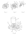
- a contact pad 2 made according to the method of the invention is illustrated.
- the first step of the method consists in identifying the shape of an elementary piece 3 having no slot, which part is intended to be reproduced in a certain number of copies, these elementary pieces 3 then being intended to be assembled in such a way as to forming a disk-shaped pellet 2 having slots 4.
- the elementary part 3 is manufactured for example by sintering without additional machining.
- the slots 4 of the contact pad 2 are formed by two facing edges 4a, 4b respectively belonging to two adjacent elementary pieces 3a, 3b.
- the pellet 2 is constituted by four elementary pieces 3a, 3b, 3c, 3d such as that illustrated on FIG. figure 3 said pieces being assembled to form a whole pellet.
- each of the elementary pieces 3 is formed by a ring quarter 5 connected on a part of its outer circumference 6 by a beak-shaped part 7, this part 7 having a circular peripheral edge 8 forming the circular peripheral edge of the contact pad 2, a rectilinear inner edge 9 and an outer lateral edge 10.
- the rectilinear inner edge 9 of an elementary piece 3a forms with the outer rectilinear edge 10a of a adjacent part 3d an orthoradial slot 11.
- the lateral outer edge 10 of the elementary part 3a forms with the rectilinear inner edge 9a of an adjacent elementary piece 3b an orthoradial rectilinear slot 11a of the contact pad 2.
- said elementary part After manufacture of the elementary part for example by sintering, said elementary part is calibrated, then annealed, in order to give the material of said part the expected physicochemical properties of the contact material.
- the piece thus manufactured can be deburred by industrial means (for example by passing the barrel).
- the contact is then reconstituted by final assembly of the various elementary parts and fixing of this assembly by a solder 12 on a contact support 13.
- this elementary part being smaller in size than the final pellet, the means of implementation, for example comprising a pelletizing press, are reduced and require less investment.
- the steps for calibrating and assembling the elementary shapes can be performed simultaneously with the aid of a shrinking piece 14, ensuring the mechanical strength of the contact, a solder 15 solidarizing the contact pad 2 to the contact support 13.
- the manufacturing method according to the invention applies in particular to vacuum interrupters of circuit breakers using the so-called axial magnetic field cleavage technique, as shown in FIG. figure 6 , or radial magnetic field as shown on the figure 7 , the slots 4 being oriented differently on the contact pad 2 according to the cutting technique used.
- the invention is also applicable to similar contacts having slots belonging to electrical switching devices. So, according to the realization of the bulb illustrated on the figure 6 , the slots 16 are radial, while according to the embodiment of the bulb illustrated on the figure 7 the slots 17 are orthoradial.
- the number of segments constituting the pellet is at least two, the maximum limitation being determined by the technological limits of elaboration.
- the method of manufacturing contact pads according to the invention is applicable to any pad intended for the manufacture of contacts comprising slots for switches, circuit breakers, contactors with vacuum technology or other, in the fields of the average , low or high voltage, whatever its destination, from the moment when the pellet can be segmented into several elementary forms without any slot involving mechanical embrittlement of the piece to be sintered.
- the invention can be used for contact pads consisting of contact material compositions for cutting short circuit currents (circuit breakers) or load currents (switches), occasionally or with high electrical endurance (contactors), for example contacts made of Cu-Cr with a mass percentage of chromium of between 10% and 60%.
- a method of manufacturing a contact pad which is particularly economical, has a reduced implementation means. Indeed, the elementary part being of smaller dimensions than the final pellet, the implementation means used (for example a pelletizing press) are reduced and require less investment.
- the invention also makes it possible to produce complex slot shapes that can hardly be obtained by machining. In addition, this type of elemental petal is easily achievable directly to the sides by metallurgy powders, this being more difficult for whole pellets because of the slots.
- the invention is not limited to the embodiments described and illustrated which have been given by way of example.
Landscapes
- Manufacture Of Switches (AREA)
- Powder Metallurgy (AREA)
Abstract
Description
- La présente invention concerne un procédé de fabrication de pastilles de contact pour un appareil de coupure électrique, ladite pastille de contact comportant au moins une fente, ainsi qu'une pastille de contact réalisée suivant le procédé précédemment mentionné.
- La fabrication des contacts électriques est réalisée de manière connue de la façon suivante. Tout d'abord, une préforme est réalisée consistant en un cylindre de diamètre légèrement supérieur au diamètre final du contact et d'épaisseur, celle du contact après usinage. Cette préforme est frittée, calibrée puis recuite afin de conférer au contact, les propriétés physico-chimiques souhaitées comprenant la conductivité électrique souhaitée.
Cette préforme est ensuite usinée pour donner au contact sa forme finale. La forme du contact contribue à la fonction coupure des ampoules à vide, notamment avec l'usinage des fentes. Cette fabrication se termine par une étape d'ébavurage, cette étape ayant pour objectif d'enlever tout angle vif laissé éventuellement par des copeaux d'usinage et affectant la tenue diélectrique du contact dans l'ampoule à vide.
Ainsi, on peut distinguer deux grandes étapes pour la réalisation d'un contact électrique : La première est une étape métallurgique de frittage de la préforme et d'obtention des propriétés physico-chimiques finales, la seconde est une étape d'usinage. Cette dernière étape ne possède pas vraiment de valeur ajoutée dans la fabrication du contact.
Ce coût d'usinage est d'autant plus important que certains fournisseurs réalisent une opération d'ébavurage manuelle, opération nécessaire dans les zones inaccessibles à des outillages, telles que le bout des fentes usinées. - La présente invention résout ces inconvénients et propose un procédé de fabrication des pastilles de contact pour un appareil de coupure électrique, de mise en oeuvre aisée et présentant un coût réduit, ainsi qu'une pastille de contact obtenue au moyen de ce procédé.
- A cet effet, la présente invention a pour objet un procédé de fabrication de pastilles de contact pour un appareil de coupure électrique, ladite pastille de contact comportant au moins une fente, ce procédé étant caractérisé en ce qu'il comporte au moins une étape d'identification et de réalisation d'une pièce élémentaire de la pastille de contact, ladite pièce ne comportant pas de fente et pouvant être reproduite plusieurs fois pour former, après un assemblage approprié desdites pièces, une pastille de contact dans sa forme finale, et une étape d'assemblage desdits pièces élémentaires de manière à obtenir ladite pastille de contact dans sa forme finale, les fentes étant réalisées par deux bords en regard de deux pièces élémentaires adjacentes.
- Selon une caractéristique particulière de l'invention, entre les étapes de réalisation et d'assemblage précitées, ledit procédé comporte une étape de calibrage puis de recuisson, lesdites étapes de calibrage et de recuisson étant destinées à conférer les propriétés physico-chimiques appropriées audit matériau de contact électrique des pièces élémentaires précitées.
- Selon une autre caractéristique, après les étapes de calibrage et de recuisson, ledit procédé comporte une étape d'ébavurage.
- Selon une autre caractéristique, après l'étape d'assemblage, ledit procédé comporte une étape de fixation dudit assemblage sur un support de contact.
- Selon une autre caractéristique particulière, les étapes de calibrage et d'assemblage des pièces élémentaires sont réalisées simultanément au moyen d'une pièce de frittage assurant la tenue mécanique du contact.
- Selon une autre caractéristique, les pièces élémentaires sont réalisées par frittage.
- L'invention a encore pour objet une pièce élémentaire de pastille de contact, ladite pièce ne comportant pas de fente et étant susceptible d'être reproduite plusieurs fois pour former, après un assemblage approprié de ces pièces, une pastille de contact dans sa forme finale, ladite pastille comportant des fentes, chacune des fentes étant réalisée par deux bords en regard appartenant respectivement à deux pièces élémentaires adjacentes.
- Selon une caractéristique particulière, cette pièce est formée par un quart d'anneau relié sur une partie de sa circonférence extérieure à une partie en forme de bec, cette partie présentant un bord périphérique circulaire formant le bord périphérique circulaire de la pastille de contact et un bord intérieur rectiligne destiné à former avec le bord latéral extérieur d'une pièce élémentaire adjacente, une fente rectiligne orthoradiale de la pastille de contact et un bord extérieur latéral destiné à former avec le bord intérieur rectiligne d'une pièce élémentaire adjacente une seconde fente orthoradiale.
- La présente invention a encore pour objet une pastille de contact, cette pastille étant caractérisée en ce qu'elle est constituée par au moins deux pièces élémentaires comportant les caractéristiques précédemment mentionnées prises seules ou en combinaison.
- Selon une autre caractéristique, les fentes appartenant à la pastille de contact sont de forme radiale ou orthoradiale.
- La présente invention a encore pour objet un appareil de coupure électrique et une ampoule à vide comportant au moins une pastille de contact, ladite pastille comportant les caractéristiques précédemment mentionnées prises seules ou en combinaison.
- Mais d'autres avantages et caractéristiques de l'invention apparaîtront mieux dans la description détaillée qui suit et se réfère aux dessins annexés donnés uniquement à titre d'exemple et dans lesquels :
- La
figure 1 est une vue en perspective d'une pastille de contact selon l'art antérieur, - La
figure 2 est une vue en perspective d'une pastille de contact selon l'invention, - La
figure 3 est une vue en perspective d'une pièce élémentaire de pastille de contact selon l'invention, - La
figure 4 est une vue en perspective, illustrant une pastille de contact selon l'invention avant sa fixation sur un support de contact, - La
figure 5 est une vue en perspective d'une pastille de contact et d'une pièce de frettage selon l'invention, - Les
figures 6 et 7 sont deux vues en perspective, illustrant respectivement deux réalisations différentes d'une pastille de contact. - Sur la
figure 1 , on voit une pastille de contact 1 selon l'art antérieur, destinée à étre montée à l'extrémité d'un contact fixe ou mobile dans une ampoule à vide, cette ampoule à vide étant destinée notamment à être intégrée à un disjoncteur électrique moyenne tension afin de réaliser la coupure d'un circuit électrique en cas de défaut. De manière connue en soi, cette ampoule à vide comprend une enveloppe cylindrique à l'intérieur de laquelle sont logées deux contacts d'arc respectivement un contact d'arc fixe et un contact d'arc mobile, ce contact mobile étant apte à être déplacé à l'intérieur de l'enveloppe entre deux positions respectivement une position de fermeture des contacts et une position d'ouverture des contacts.
Selon cette réalisation de l'art antérieur, cette pastille de contact 1 est monobloc et a été réalisée par frettage, puis usinage des fentes.
Sur lafigure 2 , une pastille de contact 2 fabriquée selon le procédé de l'invention est illustrée.
La première étape du procédé consiste à identifier la forme d'une pièce élémentaire 3 ne comportant pas de fente, laquelle pièce étant destinée à être reproduite en un certain nombre d'exemplaires, ces pièces élémentaires 3 étant ensuite destinées à être assemblées de manière à former une pastille 2 en forme de disque comportant des fentes 4.
La pièce élémentaire 3 est fabriquée par exemple par frittage sans usinage supplémentaire. Les fentes 4 de la pastille de contact 2 sont réalisées par deux bords en regard 4a,4b appartenant respectivement à deux pièces élémentaires adjacentes 3a,3b.
Selon la réalisation illustrée sur lesfigures 1 à 4 , la pastille 2 est constituée par quatre pièces élémentaires 3a,3b,3c,3d telles que celle illustrée sur lafigure 3 , lesdites pièces étant assemblées de manière à former une pastille entière. Telle qu'illustrée sur lafigure 3 , chacune des pièces élémentaires 3 est formée par un quart d'anneau 5 relié sur une partie de sa circonférence extérieure 6 par une partie en forme de bec 7, cette partie 7 présentant un bord périphérique circulaire 8 formant le bord périphérique circulaire de la pastille de contact 2, une bord intérieur rectiligne 9 et un bord latéral extérieur 10. Le bord intérieur rectiligne 9 d'une pièce élémentaire 3a forme avec le bord rectiligne extérieur 10a d'une pièce adjacente 3d une fente orthoradiale 11. De même, le bord extérieur latéral 10 de la pièce élémentaire 3a forme avec le bord intérieur rectiligne 9a d'une pièce élémentaire adjacente 3b une fente rectiligne orthoradiale 11a de la pastille de contact 2.
Après fabrication de la pièce élémentaire par exemple par frittage, ladite pièce élémentaire est calibrée, puis recuite, afin de conférer au matériau de ladite pièce les propriétés physico-chimiques escomptées du matériau de contact.
La pièce ainsi fabriquée peut être ébavurée par des moyens industriels (par exemple par passage au tonneau). L'un des bords de la pièce élémentaire constituant un bord de fente, la difficulté de l'usinage des bords des fentes qui existait lorsque la pastille de contact entière était usinée, est alors supprimée.
Le contact est ensuite reconstitué par assemblage final des différentes pièces élémentaires et fixation de cet ensemble par une brasure 12 sur un support de contact 13.
Ainsi, cette pièce élémentaire étant de dimensions plus petites que la pastille finale, les moyens de mise en oeuvre, par exemple comprenant une presse à pastiller, sont réduits et nécessitent moins d'investissement.
On notera que les étapes de calibrage et d'assemblage des formes élémentaires peuvent être réalisées simultanément à l'aide d'une pièce de frettage 14, assurant la tenue mécanique du contact, une brasure 15 solidarisant la pastille de contact 2 au support de contact 13.
Le procédé de fabrication selon l'invention s'applique notamment aux ampoules à vide des disjoncteurs utilisant la technique de coupure dite à champ magnétique axial, telles que représentées sur lafigure 6 , ou à champ magnétique radial telles que représentées sur lafigure 7 , les fentes 4 étant orientées différemment sur la pastille de contact 2 suivant la technique de coupure utilisée.
L'invention s'applique également aux contacts similaires comportant des fentes appartenant aux appareils de coupure électriques.
Ainsi, selon la réalisation de l'ampoule illustrée sur lafigure 6 , les fentes 16 sont radiales, tandis que selon la réalisation de l'ampoule illustrée sur lafigure 7 , les fentes 17 sont orthoradiales. - Le nombre de segments constituant la pastille est au minimum de deux, la limitation maximale étant déterminée par les limites technologiques d'élaboration.
Le procédé de fabrication de pastilles de contact selon l'invention s'applique à toute pastille destinée à la fabrication de contacts comportant des fentes pour les interrupteurs, les disjoncteurs, les contacteurs à technologie dans le vide ou autres, dans les domaines de la moyenne, de la basse ou de la haute tension, quelque soit sa destination, dés l'instant où la pastille peut être segmentée en plusieurs formes élémentaires sans aucune fente impliquant une fragilisation mécanique de la pièce à fritter. - L'invention peut être utilisée pour des pastilles de contact constituées de compositions de matériau de contact destinées à couper des courants de court-circuit (disjoncteurs) ou des courants de charge (interrupteurs), occasionnellement ou avec une endurance électrique élevée (contacteurs), par exemple des contacts constitués de Cu-Cr avec un pourcentage en masse de chrome compris entre 10 % et 60 %.
On a donc réalisé selon l'invention, un procédé de fabrication d'une pastille de contact, particulièrement économique, présentant des moyens de mise en oeuvre réduits.
En effet, la pièce élémentaire étant de dimensions plus petites que la pastille finale, les moyens de mise en oeuvre utilisés (exemple une presse à pastiller) sont réduits et nécessitent moins d'investissement.
L'invention permet également de réaliser des formes de fente complexes qui peuvent difficilement être obtenues par usinage.
En outre, ce type de pétale élémentaire est facilement réalisable directement aux cotes par métallurgie des poudres, ceci étant plus difficile pour des pastilles entières à cause des fentes.
Bien entendu, l'invention n'est pas limitée aux modes de réalisations décrits et illustrés qui n'ont été donnés qu'à titre d'exemple. - Au contraire, l'invention comprend tous lés équivalents techniques des moyens décrits ainsi que leurs combinaisons si celles-ci sont réalisées suivant son esprit.
Claims (12)
- Procédé de fabrication de pastilles de contact pour un appareil de coupure électrique, ladite pastille de contact comportant au moins une fente, caractérisé en ce qu'il comporte :- au moins une étape d'identification et de réalisation d'une pièce élémentaire (3a,3b,3c,3d) de la pastille de contact (2), ladite pièce ne comportant pas de fente (4) et pouvant être reproduite plusieurs fois pour former, après un assemblage approprié desdites pièces, une pastille de contact (2) dans sa forme finale, et- une étape d'assemblage desdits pièces élémentaires de manière à obtenir ladite pastille de contact dans sa forme finale, les fentes (4) étant réalisées par deux bords en regard (4a,4b) de deux pièces élémentaires adjacentes .
- Procédé de fabrication de pastilles de contact selon la revendication 1, caractérisé en ce qu'entre les étapes de réalisation et d'assemblage précitées, ledit procédé comporte une étape de calibrage puis de recuisson, lesdites étapes de calibrage et de recuisson étant destinées à conférer les propriétés physico-chimiques appropriées audit matériau de contact électrique des pièces élémentaires précitées (3a,3b,3c,3d).
- Procédé de fabrication de pastilles de contact selon la revendication 2, caractérisé en ce qu'après les étapes de calibrage et de recuisson, ledit procédé comporte une étape d'ébavurage.
- Procédé de fabrication de pastilles de contact selon l'une quelconque des revendications 1 à 3, caractérisé en ce qu'après l'étape d'assemblage, ledit procédé comporte une étape de fixation dudit assemblage sur un support de contact (13).
- Procédé de fabrication de pastilles de contact selon la revendication 2, caractérisé en ce que les étapes de calibrage et d'assemblage des pièces élémentaires (3a,3b,3c,3d) sont réalisées simultanément au moyen d'une pièce de frettage (14) assurant la tenue mécanique du contact.
- Procédé de fabrication de pastilles de contact selon l'une quelconque des revendications précédentes, caractérisé en ce que les pièces élémentaires (3a,3b,3c,3d) sont réalisées par frittage.
- Pièce élémentaire de pastille de contact, ladite pièce (3a,3b,3c,3d) ne comportant pas de fente et étant susceptible d'être reproduite plusieurs fois pour former, après un assemblage approprié de ces pièces, une pastille de contact (2) dans sa forme finale, ladite pastille comportant des fentes, chacune des fentes (4) étant réalisée par deux bords (4a,4b) en regard appartenant respectivement à deux pièces élémentaires adjacentes.
- Pièce élémentaire de pastille de contact (3a) selon la revendication 7, caractérisée en ce qu'elle est formée par un quart d'anneau (5) relié sur une partie de sa circonférence extérieure (6) à une partie en forme de bec (7), cette partie en forme de bec (7) présentant un bord périphérique circulaire (8) formant le bord périphérique circulaire de la pastille de contact (2) et un bord intérieur rectiligne (9) destiné à former avec le bord latéral extérieur (10a) d'une pièce élémentaire adjacente (3d), une fente rectiligne orthoradiale (11) de la pastille de contact (2), et un bord extérieur latéral (10) destiné à former avec le bord intérieur rectiligne (9a) d'une pièce élémentaire adjacente (3b) une seconde fente orthoradiale (11).
- Pastille de contact, caractérisée en ce qu'elle est constituée par au moins deux pièces élémentaires (3a,3b,3c,3d) selon la revendication 7 ou 8.
- Pastille de contact selon la revendication 9, caractérisée en ce que les fentes (4) appartenant à la pastille de contact (2) sont de forme radiale ou orthoradiale.
- Appareil de coupure électrique comportant au moins une pastille de contact (2) selon la revendication 9 ou 10.
- Ampoule à vide comportant au moins une pastille de contact (2) selon la revendication 9 ou 10.
Applications Claiming Priority (1)
| Application Number | Priority Date | Filing Date | Title |
|---|---|---|---|
| FR0707166A FR2922355B1 (fr) | 2007-10-12 | 2007-10-12 | Procede de fabrication de pastilles de contacts pour un appareil de coupure electrique et pastille de contact obtenue selon ce procede |
Publications (2)
| Publication Number | Publication Date |
|---|---|
| EP2048675A1 true EP2048675A1 (fr) | 2009-04-15 |
| EP2048675B1 EP2048675B1 (fr) | 2010-08-25 |
Family
ID=39386438
Family Applications (1)
| Application Number | Title | Priority Date | Filing Date |
|---|---|---|---|
| EP08354064A Active EP2048675B1 (fr) | 2007-10-12 | 2008-09-29 | Procédé de fabrication de pastilles de contacts pour un appareil de coupure électrique et pastille de contact obtenue selon ce procédé |
Country Status (5)
| Country | Link |
|---|---|
| EP (1) | EP2048675B1 (fr) |
| CN (1) | CN101409163B (fr) |
| AT (1) | ATE479192T1 (fr) |
| DE (1) | DE602008002299D1 (fr) |
| FR (1) | FR2922355B1 (fr) |
Families Citing this family (1)
| Publication number | Priority date | Publication date | Assignee | Title |
|---|---|---|---|---|
| FR2969367B1 (fr) * | 2010-12-17 | 2013-04-26 | Schneider Electric Ind Sas | Appareil de coupure electrique |
Citations (2)
| Publication number | Priority date | Publication date | Assignee | Title |
|---|---|---|---|---|
| DE2454157A1 (de) * | 1974-11-14 | 1976-05-26 | Siemens Ag | Vakuumschaltrohr |
| EP0185211A2 (fr) * | 1984-11-22 | 1986-06-25 | Hitachi, Ltd. | Interrupteur à vide |
Family Cites Families (2)
| Publication number | Priority date | Publication date | Assignee | Title |
|---|---|---|---|---|
| DE3422949A1 (de) * | 1984-06-19 | 1985-12-19 | Siemens AG, 1000 Berlin und 8000 München | Vakuumschaltroehre mit einer spule zum erzeugen eines magnetfeldes |
| JP2002334641A (ja) * | 2001-05-09 | 2002-11-22 | Meidensha Corp | 真空遮断器の電極及びその製造方法 |
-
2007
- 2007-10-12 FR FR0707166A patent/FR2922355B1/fr not_active Expired - Fee Related
-
2008
- 2008-09-29 AT AT08354064T patent/ATE479192T1/de active
- 2008-09-29 EP EP08354064A patent/EP2048675B1/fr active Active
- 2008-09-29 DE DE602008002299T patent/DE602008002299D1/de active Active
- 2008-10-10 CN CN200810169870.6A patent/CN101409163B/zh not_active Expired - Fee Related
Patent Citations (2)
| Publication number | Priority date | Publication date | Assignee | Title |
|---|---|---|---|---|
| DE2454157A1 (de) * | 1974-11-14 | 1976-05-26 | Siemens Ag | Vakuumschaltrohr |
| EP0185211A2 (fr) * | 1984-11-22 | 1986-06-25 | Hitachi, Ltd. | Interrupteur à vide |
Also Published As
| Publication number | Publication date |
|---|---|
| DE602008002299D1 (de) | 2010-10-07 |
| EP2048675B1 (fr) | 2010-08-25 |
| CN101409163B (zh) | 2013-05-29 |
| CN101409163A (zh) | 2009-04-15 |
| FR2922355B1 (fr) | 2009-12-04 |
| FR2922355A1 (fr) | 2009-04-17 |
| ATE479192T1 (de) | 2010-09-15 |
Similar Documents
| Publication | Publication Date | Title |
|---|---|---|
| EP2261940B1 (fr) | Enroulement pour contact d'ampoule a vide a moyenne tension a endurance amelioree, ampoule a vide et disjoncteur, tel qu'un disjoncteur sectionneur d'alternateur associes | |
| EP2867912B1 (fr) | Interrupteur électrique formant coupe-circuit à actionnement rapide | |
| EP2120242B1 (fr) | Interrupteur sectionneur électrique de moyenne et haute tension | |
| FR2918509A1 (fr) | Traversee metal - materiau de fixation | |
| EP2565889B1 (fr) | Appareil de coupure électrique à haute tenue électrodynamique | |
| EP1376634B1 (fr) | Ampoule à vide pour un appareil de protection électrique tel un interrupteur ou un disjoncteur | |
| EP2048675B1 (fr) | Procédé de fabrication de pastilles de contacts pour un appareil de coupure électrique et pastille de contact obtenue selon ce procédé | |
| EP4022661A1 (fr) | Interrupteur pyrotechnique | |
| EP3035363B1 (fr) | Chambre de coupure d'arc pour un disjoncteur electrique, et disjoncteur comportant une telle chambre | |
| EP0715324B1 (fr) | Interrupteur électrique, notamment sous vide | |
| EP2483900A1 (fr) | Enroulement pour contact d'ampoule à vide à moyenne tension à coupure d'arc ameliorée, ampoule à vide et disjoncteur, tel qu'un disjoncteur sectionneur d'alternateur associés | |
| EP3251140B1 (fr) | Disjoncteur équipé d'un capot d'échappement extensible | |
| EP0308847B1 (fr) | Bobine de soufflage magnétique par rotation de l'arc pour élément de contact d'un interrupteur électrique | |
| FR3155945A1 (fr) | Tige de conduction de courant électrique pour ampoule à vide | |
| EP4654238A1 (fr) | Ensemble de contacts de coupure électrique | |
| EP1700325B1 (fr) | Organe de contact electrique pour appareillage electrique en moyenne ou haute tension, procede et appareillage correspondants | |
| EP2827352B1 (fr) | Disjoncteur et procédé de fabrication d'un tel disjoncteur | |
| EP4020514B1 (fr) | Contact de coupure électrique | |
| EP2402970B1 (fr) | Chambre de coupure pour disjoncteur a moyenne ou haute tension a energie de manoeuvre et dimensions reduites | |
| EP4006939A1 (fr) | Contact d'ampoule à vide à moyenne tension à coupure d'arc améliorée et ampoule à vide associée | |
| FR3147662A1 (fr) | Coupe-circuit pyrotechnique | |
| WO2025228587A1 (fr) | Dispositif de coupure electrique | |
| EP1520282A2 (fr) | Element de contact d arc pour appareillage electrique, son p rocede de fabrication, ensemble de contact et appareillage electrique correspondants | |
| FR3056822A1 (fr) | Ampoule a vide pour appareil de connexion electrique | |
| FR2613125A1 (fr) | Piece de contact d'un disjoncteur miniature et procede de fabrication d'une telle piece a partir d'une bande bimetallique |
Legal Events
| Date | Code | Title | Description |
|---|---|---|---|
| PUAI | Public reference made under article 153(3) epc to a published international application that has entered the european phase |
Free format text: ORIGINAL CODE: 0009012 |
|
| AK | Designated contracting states |
Kind code of ref document: A1 Designated state(s): AT BE BG CH CY CZ DE DK EE ES FI FR GB GR HR HU IE IS IT LI LT LU LV MC MT NL NO PL PT RO SE SI SK TR |
|
| AX | Request for extension of the european patent |
Extension state: AL BA MK RS |
|
| 17P | Request for examination filed |
Effective date: 20090427 |
|
| 17Q | First examination report despatched |
Effective date: 20090603 |
|
| AKX | Designation fees paid |
Designated state(s): AT BE BG CH CY CZ DE DK EE ES FI FR GB GR HR HU IE IS IT LI LT LU LV MC MT NL NO PL PT RO SE SI SK TR |
|
| GRAP | Despatch of communication of intention to grant a patent |
Free format text: ORIGINAL CODE: EPIDOSNIGR1 |
|
| RIN1 | Information on inventor provided before grant (corrected) |
Inventor name: GUILLET, DENIS Inventor name: CARDOLETTI, OLIVIER Inventor name: HENON, ALBIN Inventor name: NICOLLE, CYRIL |
|
| GRAS | Grant fee paid |
Free format text: ORIGINAL CODE: EPIDOSNIGR3 |
|
| GRAA | (expected) grant |
Free format text: ORIGINAL CODE: 0009210 |
|
| AK | Designated contracting states |
Kind code of ref document: B1 Designated state(s): AT BE BG CH CY CZ DE DK EE ES FI FR GB GR HR HU IE IS IT LI LT LU LV MC MT NL NO PL PT RO SE SI SK TR |
|
| REG | Reference to a national code |
Ref country code: GB Ref legal event code: FG4D Free format text: NOT ENGLISH |
|
| REG | Reference to a national code |
Ref country code: CH Ref legal event code: EP |
|
| REG | Reference to a national code |
Ref country code: IE Ref legal event code: FG4D Free format text: LANGUAGE OF EP DOCUMENT: FRENCH |
|
| REF | Corresponds to: |
Ref document number: 602008002299 Country of ref document: DE Date of ref document: 20101007 Kind code of ref document: P |
|
| REG | Reference to a national code |
Ref country code: NL Ref legal event code: VDEP Effective date: 20100825 |
|
| LTIE | Lt: invalidation of european patent or patent extension |
Effective date: 20100825 |
|
| PG25 | Lapsed in a contracting state [announced via postgrant information from national office to epo] |
Ref country code: NO Free format text: LAPSE BECAUSE OF FAILURE TO SUBMIT A TRANSLATION OF THE DESCRIPTION OR TO PAY THE FEE WITHIN THE PRESCRIBED TIME-LIMIT Effective date: 20101125 Ref country code: LT Free format text: LAPSE BECAUSE OF FAILURE TO SUBMIT A TRANSLATION OF THE DESCRIPTION OR TO PAY THE FEE WITHIN THE PRESCRIBED TIME-LIMIT Effective date: 20100825 Ref country code: FI Free format text: LAPSE BECAUSE OF FAILURE TO SUBMIT A TRANSLATION OF THE DESCRIPTION OR TO PAY THE FEE WITHIN THE PRESCRIBED TIME-LIMIT Effective date: 20100825 |
|
| PG25 | Lapsed in a contracting state [announced via postgrant information from national office to epo] |
Ref country code: BG Free format text: LAPSE BECAUSE OF FAILURE TO SUBMIT A TRANSLATION OF THE DESCRIPTION OR TO PAY THE FEE WITHIN THE PRESCRIBED TIME-LIMIT Effective date: 20101125 Ref country code: PL Free format text: LAPSE BECAUSE OF FAILURE TO SUBMIT A TRANSLATION OF THE DESCRIPTION OR TO PAY THE FEE WITHIN THE PRESCRIBED TIME-LIMIT Effective date: 20100825 Ref country code: CY Free format text: LAPSE BECAUSE OF FAILURE TO SUBMIT A TRANSLATION OF THE DESCRIPTION OR TO PAY THE FEE WITHIN THE PRESCRIBED TIME-LIMIT Effective date: 20100825 Ref country code: IS Free format text: LAPSE BECAUSE OF FAILURE TO SUBMIT A TRANSLATION OF THE DESCRIPTION OR TO PAY THE FEE WITHIN THE PRESCRIBED TIME-LIMIT Effective date: 20101225 Ref country code: SI Free format text: LAPSE BECAUSE OF FAILURE TO SUBMIT A TRANSLATION OF THE DESCRIPTION OR TO PAY THE FEE WITHIN THE PRESCRIBED TIME-LIMIT Effective date: 20100825 Ref country code: HR Free format text: LAPSE BECAUSE OF FAILURE TO SUBMIT A TRANSLATION OF THE DESCRIPTION OR TO PAY THE FEE WITHIN THE PRESCRIBED TIME-LIMIT Effective date: 20100825 |
|
| REG | Reference to a national code |
Ref country code: IE Ref legal event code: FD4D |
|
| BERE | Be: lapsed |
Owner name: SCHNEIDER ELECTRIC INDUSTRIES SAS Effective date: 20100930 |
|
| PG25 | Lapsed in a contracting state [announced via postgrant information from national office to epo] |
Ref country code: GR Free format text: LAPSE BECAUSE OF FAILURE TO SUBMIT A TRANSLATION OF THE DESCRIPTION OR TO PAY THE FEE WITHIN THE PRESCRIBED TIME-LIMIT Effective date: 20101126 Ref country code: NL Free format text: LAPSE BECAUSE OF FAILURE TO SUBMIT A TRANSLATION OF THE DESCRIPTION OR TO PAY THE FEE WITHIN THE PRESCRIBED TIME-LIMIT Effective date: 20100825 Ref country code: SE Free format text: LAPSE BECAUSE OF FAILURE TO SUBMIT A TRANSLATION OF THE DESCRIPTION OR TO PAY THE FEE WITHIN THE PRESCRIBED TIME-LIMIT Effective date: 20100825 Ref country code: LV Free format text: LAPSE BECAUSE OF FAILURE TO SUBMIT A TRANSLATION OF THE DESCRIPTION OR TO PAY THE FEE WITHIN THE PRESCRIBED TIME-LIMIT Effective date: 20100825 |
|
| PG25 | Lapsed in a contracting state [announced via postgrant information from national office to epo] |
Ref country code: IE Free format text: LAPSE BECAUSE OF FAILURE TO SUBMIT A TRANSLATION OF THE DESCRIPTION OR TO PAY THE FEE WITHIN THE PRESCRIBED TIME-LIMIT Effective date: 20100825 Ref country code: DK Free format text: LAPSE BECAUSE OF FAILURE TO SUBMIT A TRANSLATION OF THE DESCRIPTION OR TO PAY THE FEE WITHIN THE PRESCRIBED TIME-LIMIT Effective date: 20100825 Ref country code: MC Free format text: LAPSE BECAUSE OF NON-PAYMENT OF DUE FEES Effective date: 20100930 |
|
| PG25 | Lapsed in a contracting state [announced via postgrant information from national office to epo] |
Ref country code: SK Free format text: LAPSE BECAUSE OF FAILURE TO SUBMIT A TRANSLATION OF THE DESCRIPTION OR TO PAY THE FEE WITHIN THE PRESCRIBED TIME-LIMIT Effective date: 20100825 Ref country code: IT Free format text: LAPSE BECAUSE OF FAILURE TO SUBMIT A TRANSLATION OF THE DESCRIPTION OR TO PAY THE FEE WITHIN THE PRESCRIBED TIME-LIMIT Effective date: 20100825 Ref country code: RO Free format text: LAPSE BECAUSE OF FAILURE TO SUBMIT A TRANSLATION OF THE DESCRIPTION OR TO PAY THE FEE WITHIN THE PRESCRIBED TIME-LIMIT Effective date: 20100825 Ref country code: EE Free format text: LAPSE BECAUSE OF FAILURE TO SUBMIT A TRANSLATION OF THE DESCRIPTION OR TO PAY THE FEE WITHIN THE PRESCRIBED TIME-LIMIT Effective date: 20100825 Ref country code: CZ Free format text: LAPSE BECAUSE OF FAILURE TO SUBMIT A TRANSLATION OF THE DESCRIPTION OR TO PAY THE FEE WITHIN THE PRESCRIBED TIME-LIMIT Effective date: 20100825 |
|
| PG25 | Lapsed in a contracting state [announced via postgrant information from national office to epo] |
Ref country code: ES Free format text: LAPSE BECAUSE OF FAILURE TO SUBMIT A TRANSLATION OF THE DESCRIPTION OR TO PAY THE FEE WITHIN THE PRESCRIBED TIME-LIMIT Effective date: 20101206 |
|
| PLBE | No opposition filed within time limit |
Free format text: ORIGINAL CODE: 0009261 |
|
| STAA | Information on the status of an ep patent application or granted ep patent |
Free format text: STATUS: NO OPPOSITION FILED WITHIN TIME LIMIT |
|
| PG25 | Lapsed in a contracting state [announced via postgrant information from national office to epo] |
Ref country code: BE Free format text: LAPSE BECAUSE OF NON-PAYMENT OF DUE FEES Effective date: 20100930 |
|
| 26N | No opposition filed |
Effective date: 20110526 |
|
| REG | Reference to a national code |
Ref country code: DE Ref legal event code: R097 Ref document number: 602008002299 Country of ref document: DE Effective date: 20110526 |
|
| PG25 | Lapsed in a contracting state [announced via postgrant information from national office to epo] |
Ref country code: MT Free format text: LAPSE BECAUSE OF FAILURE TO SUBMIT A TRANSLATION OF THE DESCRIPTION OR TO PAY THE FEE WITHIN THE PRESCRIBED TIME-LIMIT Effective date: 20100825 |
|
| PG25 | Lapsed in a contracting state [announced via postgrant information from national office to epo] |
Ref country code: HU Free format text: LAPSE BECAUSE OF FAILURE TO SUBMIT A TRANSLATION OF THE DESCRIPTION OR TO PAY THE FEE WITHIN THE PRESCRIBED TIME-LIMIT Effective date: 20110226 Ref country code: LU Free format text: LAPSE BECAUSE OF NON-PAYMENT OF DUE FEES Effective date: 20100929 |
|
| PG25 | Lapsed in a contracting state [announced via postgrant information from national office to epo] |
Ref country code: TR Free format text: LAPSE BECAUSE OF FAILURE TO SUBMIT A TRANSLATION OF THE DESCRIPTION OR TO PAY THE FEE WITHIN THE PRESCRIBED TIME-LIMIT Effective date: 20100825 |
|
| GBPC | Gb: european patent ceased through non-payment of renewal fee |
Effective date: 20120929 |
|
| PG25 | Lapsed in a contracting state [announced via postgrant information from national office to epo] |
Ref country code: GB Free format text: LAPSE BECAUSE OF NON-PAYMENT OF DUE FEES Effective date: 20120929 Ref country code: PT Free format text: LAPSE BECAUSE OF NON-PAYMENT OF DUE FEES Effective date: 20100825 |
|
| REG | Reference to a national code |
Ref country code: FR Ref legal event code: PLFP Year of fee payment: 9 |
|
| PGFP | Annual fee paid to national office [announced via postgrant information from national office to epo] |
Ref country code: CH Payment date: 20160914 Year of fee payment: 9 |
|
| PGFP | Annual fee paid to national office [announced via postgrant information from national office to epo] |
Ref country code: AT Payment date: 20160826 Year of fee payment: 9 |
|
| REG | Reference to a national code |
Ref country code: FR Ref legal event code: PLFP Year of fee payment: 10 |
|
| REG | Reference to a national code |
Ref country code: CH Ref legal event code: PL |
|
| REG | Reference to a national code |
Ref country code: AT Ref legal event code: MM01 Ref document number: 479192 Country of ref document: AT Kind code of ref document: T Effective date: 20170929 |
|
| PG25 | Lapsed in a contracting state [announced via postgrant information from national office to epo] |
Ref country code: LI Free format text: LAPSE BECAUSE OF NON-PAYMENT OF DUE FEES Effective date: 20170930 Ref country code: CH Free format text: LAPSE BECAUSE OF NON-PAYMENT OF DUE FEES Effective date: 20170930 |
|
| PG25 | Lapsed in a contracting state [announced via postgrant information from national office to epo] |
Ref country code: AT Free format text: LAPSE BECAUSE OF NON-PAYMENT OF DUE FEES Effective date: 20170929 |
|
| REG | Reference to a national code |
Ref country code: FR Ref legal event code: PLFP Year of fee payment: 11 |
|
| PGFP | Annual fee paid to national office [announced via postgrant information from national office to epo] |
Ref country code: DE Payment date: 20250926 Year of fee payment: 18 |
|
| PGFP | Annual fee paid to national office [announced via postgrant information from national office to epo] |
Ref country code: FR Payment date: 20250925 Year of fee payment: 18 |