-
The present invention relates to a heat exchanger using cooling flowing medium that runs through tubes fluidically connected between tanks.
-
A conventional heat exchanger is disclosed in Japanese Patent Application laid-open publication No.
2007 - 107799 . This conventional heat exchanger includes a pair of long tanks, a plurality of tubes and a plurality of fins. The tanks are arranged apart from each other in a vertical direction, where an upper one of them is provided with an inlet port and a lower one thereof is provided with an outlet port. The tubes are disposed between the tanks, both end portions of the tubes being inserted into and fixed to the tanks, respectively. This enables flowing medium, such as coolant, to flow into the upper tank through the inlet port and then flow to the lower tank through the tubes, finally being discharged through the outlet port from the lower tank. The fins are arranged between the adjacent tubes so as to cool the flowing medium while it passes through the tubes.
-
The above known conventional heat exchanger, however, encounters a problem in that durability of the heat exchanger is deteriorated due to thermal stress caused because of the following reasons.
-
In the conventional heat exchanger, when a high-temperature flowing medium enters the upper tank, corresponding to an upstream side tank, through the inlet port, a low-temperature flowing medium existing near the inlet port is swiftly pushed out toward the lower tank, corresponding to a downstream side tank, while the low temperature flowing medium existing at a portion of the heat exchanger that is far away from the inlet port cannot be swiftly pushed out toward the lower tank. It takes a long time for the high-temperature flowing medium to reach the far-away portion and replace the low-temperature flowing medium existing there.
-
In this state, the low-temperature flowing medium near the inlet port is moved toward the lower tank, being heated up due to direct mixture with the high-temperature flowing medium, while the low-temperature flowing medium at the portion that is wide apart from the inlet port is also pushed to move toward the lower tank without being heated up due to the mixture with the high-temperature flowing medium.
-
It causes a significant variation in temperature distribution of the flowing medium existing in the upstream side tank so that the variation becomes larger as the high-temperature flowing medium repeats flowing in and out from the heat exchanger. It further causes a notable temperature difference among the tubes according to their locations. Consequently, different thermal expansions thereof are generated among the tubes to deteriorate the durability of the heat exchanger.
-
It is, therefore, an object of the present invention to seek to provide a heat exchanger which overcomes the foregoing drawbacks and can decrease thermal stress differences of a tank and a core part, thereby improving durability of the heat exchanger.
-
According to an aspect of the present invention there is provided a heat exchanger, in which flowing medium flows, including a first tank, a second tank, a core part and a flow accelerating means. The first tank is provided with an inlet port, and the second tank is disposed apart from the first tank. The core part has a plurality of tubes and a plurality of fins, the tubes having both end portions being fluidically connected with the first tank and the second tank, respectively, and each of the fins being arranged between the adjacent tubes. The flow accelerating means is provided inside the first tank so as to accelerate a flow speed of the flowing medium, which enters an inner space of the first tank through the inlet port, in the first tank in a longitudinal direction of the first tank.
-
Therefore, the heat exchanger of the present invention can decrease thermal stress differences of a tank and a core part, thereby improving durability of the heat exchanger.
-
The objects, features and advantages of the present invention will become apparent as the description proceeds when taken in conjunction with the accompanying drawings, in which:
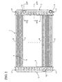
- FIG. 1 is a rear view showing a radiator as a heat exchanger of a first embodiment according to the present invention;
- FIG. 2 is a rear view showing a core part of the radiator of the first embodiment shown in FIG. 1;
- FIG. 3 is an enlarged cross sectional view showing an inlet port and its peripheral parts of the radiator of the first embodiment, taken along a line S3 - S3 in FIG 1;
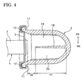
- FIG. 4 is an enlarged cross sectional view showing a tank with a first rib portion of the radiator of the first embodiment, taken along a line S4 - S4 in FIG 1;
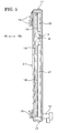
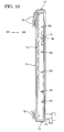
- FIG. 5 is a cross sectional side view showing the tank shown in FIG 1;
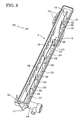
- FIG. 6 is a perspective view showing the tank shown in FIG. 1;
- FIG. 7 is a cross sectional side view showing a tank of a heat exchanger of a second embodiment according to the present invention;
- FIG. 8 is a perspective view showing the tank shown in FIG 7;
- FIG. 9 is a perspective view showing a tank of a heat exchanger of a third embodiment according to the present invention;
- FIG. 10 is a cross sectional side view showing a tank of a heat exchanger of a fourth embodiment according to the present invention;
- FIG 11 is a perspective view of the tank shown in FIG. 10;
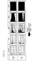
- FIG. 12 is a table showing experimental results of the radiator of the first embodiment of the present invention;
- FIG. 13 is an enlarged cross sectional view showing a tank of a modification according to the present invention;
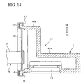
- FIG. 14 is an enlarged cross sectional view showing a tank of another modification according to the present invention.
-
Throughout the following detailed description, similar reference characters and numbers refer to similar elements in all figures of the drawings, and their descriptions are omitted for eliminating duplication.
-
In the accompany drawings, "FR" indicates a front side direction of a motor vehicle, and "RR" indicates a rear side direction thereof.
-
Referring to FIG. 1 and FIG. 2, there is shown a first preferred embodiment of a heat exchanger according to the present invention. The heat exchanger is a radiator 1 in this embodiment, and the radiator 1 is installed on a not-shown front end portion of a vehicle body of a motor vehicle, such as an automobile, in this embodiment.
-
The radiator 1 has a pair of long tanks 2 and 3 and a core part 4.
-
The right tank 2 and the left tank 3 are apart from each other in a lateral direction of the vehicle body and are made of plastic material. The right tank 2 corresponds to a first tank of the present invention, and the left tank 3 corresponds to a second tank of the present invention. Their detail construction will be later described.
-
The core part 4 is disposed between the right tank 2 and the right tank 3, being made of aluminum. The core part 4 includes a right tube plate 5, a left tube plate 6, a plurality of flat tubes 7, a pair of corrugated fins 8 and a pair of reinforcements 9 and 10.
-
The right and left tube plates 5 and 6 extend vertically and are formed with a plurality of holes for respectively receiving both end portions of the tubes 7. The both end portions of the tubes 7 extend in the lateral direction to be inserted into the holes and are fixed to the right and left tube plates 5 and 6, respectively. Each of the corrugate fins 8 is arranged between the adjacent tubes 7, extending in the lateral direction. Both end portions of the upper reinforcement 9 and the lower reinforcement 10 are inserted into and fixed to the right and left tube plates 5 and 6 at a top portion of the core part 4 and a bottom portion thereof, respectively.
-
At least one side portions of connecting portions that are temporally assembled are provided with a clad layer of brazing material, or a brazing sheet. This temporally assembled core part 4 is heat-treated in a heating furnace to be integrally formed.
-
As shown in FIG. 3 and FIG. 4, the right and left tanks 2 and 3 are fixed to the heat-treated core part 4 by means of a plurality of claw portions 11 formed on the right and left tube plates 5 and 6. Specifically, the claw portions 11 are caulked to outer circumferential portions of the right and left tanks 2 and 3, respectively, with a seal member placed therebetween at the outer circumferential portions so that inner spaces of the tanks 2 and 3 can be tightly sealed.
-
The right tank 2 is formed like a vessel, which is formed with an opening at its core part side. The right tank 2 is provided with an inlet port 13 of the flowing medium on its upper and rear side surface, further being provided with a drain port 14 on its bottom surface. On the other hand, the left tank 3 is also formed like a vessel, which is formed with an opening at its core part side and is provided with an outlet port 15 of the flowing medium on its lower and rear side surface.
-
In this embodiment, a not-shown inlet pipe and a not-shown outlet pipe are inserted into and fixed to the inlet port 13 and the outlet port 15, respectively. The pipes may be formed with the tanks 2 and 3 as one unit.
-
As shown in FIG. 5 and FIG. 6, upper and lower attachment brackets 16 are formed on front side surfaces of the tanks 2 and 3, being apart from each other I the vertical direction, so that they can fix and support a not-shown condenser on the radiator 1. Further, the tanks 2 and 3 are formed a with a mounting pin 17 on each top surface thereof for supporting the radiator 1 together with the condenser on a not-shown radiator core support and the like as a part of the vehicle body.
-
As shown in FIG. 3 to FIG. 6, in the inner space of the right tank 2, a first rib portion 18 is formed like a plate that projects by a predetermined height H1, as shown in FIG 4, from its bottom inner surface toward the tube 7, forming a clearance with a length H2 in a lateral direction of the tank 2 between a tip portion of the first rib portion 18 and the end portion of the tubes 7. The first rib portion 18 extends in the lateral direction of the tank 2 and in the vertical direction thereof, namely along a longitudinal direction of the right tank 2, being made of plastic material as one unit with the right tank 2. The first rib portion 18 corresponds to a first wall portion of the present invention.
-
The first rib portion 18 is bent toward the inlet port 13 in the vicinity thereof the inlet as shown in FIG 5 and FIG 6, and its upper bent portion is continuously connected with an upper side of the inlet port 13 and its lower bent portion is continuously connected with a lower side of the inlet port 13. This divides the inner space of the right tank 2 into a front side passage 19 and two rear side passages 20 and 21. Namely, a flow area of the front side passage 19 is set to be narrower than that of the inlet port 13, and the front side passage 19 is directly connected with the inlet port 13, extending along the longitudinal direction of the right tank 2. The upper rear side passage 20 and the lower rear side passage 21 are prevented from being directly connected with the inlet port 13. The first rib portion 18 corresponds to a flow accelerating means of the present invention. The front side passage 19 corresponds to a first passage of the present invention, and the rear side passages 20 and 21 correspond to a second passage of the present invention.
-
The left tank 3 is constructed similarly to the right tank 2 except that it has no first rib portion and no drain port and that the outlet port 15, instead of the inlet port 13 of the right tank 2, is provided at the lower rear surface of the left tank 3. Accordingly, a description of its construction is omitted herein.
-
Thus constructed radiator 1 is fixed and supported on the radiator core support by using the mounting pins 17, together with the condenser fixed and supported on the front side of the radiator 1 by using the attachment brackets 16.
-
Then, the pipe is inserted into and fixed to the inlet port 13, and then it is connected with a not-shown connecting pipe so that the flowing medium can flow therethrough after the medium cools an object to be cooled, such as an engine or an inverter circuit of an electric motor. On the other hand, the other pipe is inserted into and fixed to the outlet port 15, and then it is connected wit a not-shown connecting pipe so that the flowing medium can flow therethrough before the medium cools the object.
-
The operation and effects of the radiator 1 of the first embodiment will be described.
-
The high-temperature flowing medium, which enters the right tank 2 through the inlet port 13, is cooled down due to heat exchanger between the flowing medium and an air flow generated by the motor vehicle running (and/or an air flow generated by a motor fan), while it flows to the left tank 3 through the tubes 7 of the core part 4. The low-temperature flowing medium in the left tank 3 is discharged through the outlet port 10 to be supplied to the object. The flowing medium cooled down the object, and then returns to the inlet port 13 of the radiator 1 to circulate in this cooling circuit.
-
In this operation, after the high-temperature flowing medium enters the inner space of the right tank 2 through the inlet port 13, its flow speed is accelerated, because it is guided by the rim portion 18 to flow through the front side passage 19, of the right tank 2, that the first rib portion 18 narrows, as indicated by a dashed line M in FIG. 5. This high-temperature flowing medium reaches the top and bottom portions of the front side passage 19 in a short time, being mixed up with the low-temperature flowing medium existing at and near the top and bottom portions. This swiftly mixed-up flowing medium is pushed out from the right tank 2 to the left tank 3 through the tubes 7.
-
On the other hand, the low-temperature flowing medium in the rear side passages 20 and 21 of the right tank 2 is mixed up with the high-temperature flowing medium existing in the front side passage 19 through the clearance, having the length H2, between the first rib portion 18 and the tubes 7. This mix-up increases the temperature of the low-temperature flowing medium, decreasing the temperature of the high-temperature flowing medium, in the right tank 2.
-
In other words, the first rib portion 18 guides the high-temperature flowing medium so as to preferentially flow it through the narrow front side passage 19, which can shorten the amount of time for the high-temperature flowing medium to reach the top and bottom portions, being far away from the inlet port 13, of the right tank 2. In addition, replacement between the high-temperature flowing medium and the low-temperature flowing medium can be swiftly carried out in the right tank 2, so that the temperature inside of the right tank 2 can be approximately uniform at any position in a short time.
-
In addition, it shortens the amount of time for the flowing medium to flow through all the tube 7 at approximately uniform temperature, a temperature distribution of the core part 4 can be approximately uniform in a short time. Therefore, thermal stress due to considerable variation in the temperature distribution of the right tank 2 and the core part 4 can be decreased, which can improve the durability of the radiator 1.
-
Further, the front side passage 19 is provided at a wall portion side opposite to a wall portion formed with the inlet port 13, which can decrease flow resistance of the flowing medium immediately after it enters the right tank 2 through the inlet port 13 compared to that in a case where the front side passage 19 is provided at the wall portion side formed with the inlet port 13.
-
Further, the first rib portion 18 and the right tank 2 can be formed as one unit easily and at a low manufacturing cost compared to those that are independently formed and then are integrally connected with each other.
-
The first rib portion 18 can decrease thermal stress generated at connecting portions of the tubes 7 and the tube plate 5, on which the thermal stress notably acts, in the right tank 2, namely the upstream side tank, temperature variation of which becomes larger than that of the left tank 3, namely the downstream side tank.
-
Next, a second embodiment of the present invention will be described.
As shown in FIG 7 and FIG 8, in a radiator of the second embodiment, a first rib portion 18 is provided inside a right tank 2 similarly to the first embodiment, but a plurality of second rib portions 30 are added between the first rib portion 18 and a wall portion formed with an inlet port 13 of the right tank 2, extending in a direction perpendicular to a longitudinal direction of the right tank 2. The second rib portions 30 are made of plastic material as one unit with the right tank 2 and the first rib portion 18, having the same heights as those of the first rib portion 18. The second rib portions correspond to a second wall portion of the present invention.
-
Incidentally, the first rib portion 18 has a plurality of injection portions 38, which are formed like a circular cylinder at not-shown gates by curing of molten plastic manual injected therethrough. These injection portions 38 are not indispensable.
-
These first and second rib portions 18 and 30 divided an inner space of the right tank 2 into a front side passage 19 at a wall portion side opposite to the wall portion formed with the inlet port 30 and a plurality of chambers consisting of two upper chambers 31 and 32 and five lower chambers 33 to 37. The chambers 31 to 37 have clearances for fluidically communicating with the front side passage 19, and they correspond to the second passage of the present invention.
-
In the radiator of the second embodiment, high-temperature flowing medium entering the front side passage 19 through the inlet port increases its flow speed due to a narrow flow area thereof to swiftly flow to a top portion and a bottom portion of the inner space of the right tank 2, being mixed up with low-temperature flowing medium existing in the front side passage 19 in a short time. Then the flowing medium flow to a left tank through all of not-shown tubes used for a core part at approximately uniform temperature.
-
On the other hand, the low-temperature flowing medium in the chambers 31 - 37 is mixed up with the high-temperature, flowing medium flowing through the front side passage 19, via a clearance formed between tip portions of the first and second rib portions 18 and 30 and the wall portion formed by a not-shown tube plate. In this mix-up state, the second rib portions 30 obstruct the low-temperature flowing medium to flow in the longitudinal direction of the right tank 2, thereby accelerating mix-up of the low-temperature flowing medium in the chambers 31 - 37 and the high-temperature flowing medium in the front side passage 19.
-
Therefore, the radiator of the second embodiment can provide the following effects in addition to those of the first embodiment.
-
In the radiator of the second embodiment, the high-temperature flowing medium can be preferentially guided into the narrow front side passage 19 to accelerate its flow speed in the right tank 2. In addition, the second rib portions 30 can accelerate a speed of replacement, or mix-up, between the high-temperature flowing medium and the low-temperature flowing medium in the right tank 2, thereby providing approximately uniform temperature distribution in the right tank 2.
-
Next, a third embodiment of the present invention will be described.
-
As shown in FIG 9, in a radiator of the third embodiment, the heights of a first rib portion 18 and first-rib-portion side portions of second rib portions 30 are set to be lower than those of the second embodiment. The other parts are constructed similarly to those of the first embodiment.
-
Therefore, the radiator of the third embodiment can provide the following effect in addition to those of the second embodiment.
-
The first rib portion 18 and the portions of the second rib portions 30 are formed lower, which can simplify a shaping die for a tank formed by using resin mold, thereby saving a cost of the shaping die.
-
Next, a fourth embodiment of the present invention will be described.
-
As shown in FIG. 10 and FIG. 11, in a radiator of the fourth embodiment, a first rib portion 18 shown in the second embodiment is removed, and rib second rib portions 30 are provided similarly to those of the third embodiment. The other parts are constructed similarly to those of the first embodiment.
-
Therefore, the radiator of the fourth embodiment can provide the following effect in addition to those of the second embodiment.
-
In the radiator of the fourth embodiment, high-temperature flowing medium preferentially guided into a narrow front side passage 19 to accelerate its flow speed in a right tank 2, further accelerating a speed of replacement, or mix-up, between the high-temperature flowing medium and the low-temperature flowing medium in the right tank 2, thereby providing approximately uniform temperature distribution in the right tank 2.
-
FIG 12 shows the effects of the radiator of the first embodiment, and the effects are similarly obtained in the second to fourth embodiments.
-
In a table of FIG 12, elapse time is shown at a first part of the table, an analysis result of the radiator 1 without the first and second rib portions 13 and 30 is shown at a second part thereof, and an analysis result of the radiator 1 with the first rib portion 18, corresponding to the first embodiment, at a third part thereof. Note that the right tank 2 is shown at the left side and the left tank 3 is shown at the right side in FIG. 12. Therefore, the flowing medium flows from the left side to the right side in FIG. 12. As the temperatures (Temp.) in the radiator 1 are shown in FIG 12, being divided into three temperature areas "Hi", "Middle" and "Low". "Hi" indicates 89.2°C - 95 °C, which is sufficient temperature, "Middle" indicates 83.75 °C - 89.2 °C excluding 89.2 °C, and "Low" indicates less than 89.2 °C.
-
The experiment was carried out in such a way that at the beginning the radiator was cooled by being supplied with the low-temperature flowing medium and then the high-temperature flowing medium was supplied to the right tank 2 with counting time. In order to obtain its higher accuracy of the analysis result, the analysis was performed, its data being compared with the experimental results.
-
After one second, the temperature of the right tank 2, shown as a wide vertical bar at the left side in FIG. 12, with the first rib portion 18 becomes approximately uniform at almost all portions of the right tank 2, although the temperature of the right tank 2 without the first and second rib portions 18 and 30 becomes uneven in the right tank 2, where the temperatures of the top portion and the bottom portion of the right tank 2 are notably lower than that of its middle portion at one second.
-
This shows that the radiators of the embodiments are superior to the conventional radiator, in accelerating the temperature so that it becomes uniform at the right tank 2.
-
While there have been particularly shown and described with reference to preferred embodiments thereof, it will be understood that various modifications may be made therein.
-
For example, as shown in FIG 13, the flow accelerating means may employ a U-letter shaped portion 40 that is formed to dent toward the inlet port 13 to form a first passage between the inlet port 13 and a bottom wall of the U-letter shaped portion 40. A flow area therebetween is formed to be narrower than that of the inlet port 13. The U-letter shaped portion 40 corresponds to the first wall portion of the present invention.
-
The flow accelerating means may employ an L-letter shaped portion 41, partially dented in a height direction, which has a short height portion 41a and a long height portion 41b so that the first passage and a part of the second passage are formed between the short height potion 41a and the inlet port 13, and so that the rests of the second passages are formed between the short height potion 41a and the wall portion with the inlet port 13 and between the long height portion 41b and the wall portion with the inlet port 13. The short height potion 41a of the L-letter shaped portion 41 corresponds to the first wall portion of the present invention.
-
The heat exchanger is not limited to the radiator, and it may be a condenser or others.
-
A position of the inlet port 13, and configurations, dimensions, such as thicknesses and heights, and the numbers of the first rib portion 18 and the second rib portion 30 may be set appropriately.
-
The flow accelerating means may be provided to the second tank in addition to the first tank.
-
In the embodiments, the right tank 2 is the first tank and the left tank 3 is the second tank, to which the first tank and the second tank are not limited.
-
The first tank may be one of right and left tanks or one of upper and lower tanks as long as it has an inlet port.
-
The tanks, which are made of plastic material in the embodiments, may be made of aluminum.
-
The first rib portion 18 and the second rib portion 30 may be made of metal material and is integrally formed with the tank by using insert molding.