EP2048325A2 - A vane and a vane assembly for a gas turbine engine - Google Patents
A vane and a vane assembly for a gas turbine engine Download PDFInfo
- Publication number
- EP2048325A2 EP2048325A2 EP08253007A EP08253007A EP2048325A2 EP 2048325 A2 EP2048325 A2 EP 2048325A2 EP 08253007 A EP08253007 A EP 08253007A EP 08253007 A EP08253007 A EP 08253007A EP 2048325 A2 EP2048325 A2 EP 2048325A2
- Authority
- EP
- European Patent Office
- Prior art keywords
- vane
- internal structural
- structural member
- members
- gas turbine
- Prior art date
- Legal status (The legal status is an assumption and is not a legal conclusion. Google has not performed a legal analysis and makes no representation as to the accuracy of the status listed.)
- Granted
Links
- 229910052751 metal Inorganic materials 0.000 claims description 8
- 239000002184 metal Substances 0.000 claims description 8
- 239000012530 fluid Substances 0.000 claims description 2
- 238000005728 strengthening Methods 0.000 claims 1
- 239000000463 material Substances 0.000 description 4
- 238000000034 method Methods 0.000 description 3
- 230000001141 propulsive effect Effects 0.000 description 3
- 230000007480 spreading Effects 0.000 description 3
- 239000002131 composite material Substances 0.000 description 2
- 125000004122 cyclic group Chemical group 0.000 description 2
- 239000004033 plastic Substances 0.000 description 2
- 229920003023 plastic Polymers 0.000 description 2
- 230000008439 repair process Effects 0.000 description 2
- RTAQQCXQSZGOHL-UHFFFAOYSA-N Titanium Chemical compound [Ti] RTAQQCXQSZGOHL-UHFFFAOYSA-N 0.000 description 1
- 238000000071 blow moulding Methods 0.000 description 1
- 238000002485 combustion reaction Methods 0.000 description 1
- 230000006835 compression Effects 0.000 description 1
- 238000007906 compression Methods 0.000 description 1
- 238000010276 construction Methods 0.000 description 1
- 238000009792 diffusion process Methods 0.000 description 1
- 230000003628 erosive effect Effects 0.000 description 1
- 239000000446 fuel Substances 0.000 description 1
- 238000002347 injection Methods 0.000 description 1
- 239000007924 injection Substances 0.000 description 1
- 238000012423 maintenance Methods 0.000 description 1
- 230000007246 mechanism Effects 0.000 description 1
- 239000012528 membrane Substances 0.000 description 1
- 239000000203 mixture Substances 0.000 description 1
- 238000012986 modification Methods 0.000 description 1
- 230000004048 modification Effects 0.000 description 1
- 239000007787 solid Substances 0.000 description 1
- 239000010936 titanium Substances 0.000 description 1
- 229910052719 titanium Inorganic materials 0.000 description 1
- 238000011144 upstream manufacturing Methods 0.000 description 1
- 239000013585 weight reducing agent Substances 0.000 description 1
Images
Classifications
-
- F—MECHANICAL ENGINEERING; LIGHTING; HEATING; WEAPONS; BLASTING
- F01—MACHINES OR ENGINES IN GENERAL; ENGINE PLANTS IN GENERAL; STEAM ENGINES
- F01D—NON-POSITIVE DISPLACEMENT MACHINES OR ENGINES, e.g. STEAM TURBINES
- F01D5/00—Blades; Blade-carrying members; Heating, heat-insulating, cooling or antivibration means on the blades or the members
- F01D5/12—Blades
- F01D5/14—Form or construction
- F01D5/147—Construction, i.e. structural features, e.g. of weight-saving hollow blades
-
- F—MECHANICAL ENGINEERING; LIGHTING; HEATING; WEAPONS; BLASTING
- F01—MACHINES OR ENGINES IN GENERAL; ENGINE PLANTS IN GENERAL; STEAM ENGINES
- F01D—NON-POSITIVE DISPLACEMENT MACHINES OR ENGINES, e.g. STEAM TURBINES
- F01D9/00—Stators
- F01D9/02—Nozzles; Nozzle boxes; Stator blades; Guide conduits, e.g. individual nozzles
- F01D9/04—Nozzles; Nozzle boxes; Stator blades; Guide conduits, e.g. individual nozzles forming ring or sector
- F01D9/042—Nozzles; Nozzle boxes; Stator blades; Guide conduits, e.g. individual nozzles forming ring or sector fixing blades to stators
-
- F—MECHANICAL ENGINEERING; LIGHTING; HEATING; WEAPONS; BLASTING
- F01—MACHINES OR ENGINES IN GENERAL; ENGINE PLANTS IN GENERAL; STEAM ENGINES
- F01D—NON-POSITIVE DISPLACEMENT MACHINES OR ENGINES, e.g. STEAM TURBINES
- F01D9/00—Stators
- F01D9/06—Fluid supply conduits to nozzles or the like
- F01D9/065—Fluid supply or removal conduits traversing the working fluid flow, e.g. for lubrication-, cooling-, or sealing fluids
-
- F—MECHANICAL ENGINEERING; LIGHTING; HEATING; WEAPONS; BLASTING
- F05—INDEXING SCHEMES RELATING TO ENGINES OR PUMPS IN VARIOUS SUBCLASSES OF CLASSES F01-F04
- F05D—INDEXING SCHEME FOR ASPECTS RELATING TO NON-POSITIVE-DISPLACEMENT MACHINES OR ENGINES, GAS-TURBINES OR JET-PROPULSION PLANTS
- F05D2220/00—Application
- F05D2220/30—Application in turbines
- F05D2220/32—Application in turbines in gas turbines
- F05D2220/321—Application in turbines in gas turbines for a special turbine stage
- F05D2220/3216—Application in turbines in gas turbines for a special turbine stage for a special compressor stage
-
- F—MECHANICAL ENGINEERING; LIGHTING; HEATING; WEAPONS; BLASTING
- F05—INDEXING SCHEMES RELATING TO ENGINES OR PUMPS IN VARIOUS SUBCLASSES OF CLASSES F01-F04
- F05D—INDEXING SCHEME FOR ASPECTS RELATING TO NON-POSITIVE-DISPLACEMENT MACHINES OR ENGINES, GAS-TURBINES OR JET-PROPULSION PLANTS
- F05D2230/00—Manufacture
- F05D2230/60—Assembly methods
-
- F—MECHANICAL ENGINEERING; LIGHTING; HEATING; WEAPONS; BLASTING
- F05—INDEXING SCHEMES RELATING TO ENGINES OR PUMPS IN VARIOUS SUBCLASSES OF CLASSES F01-F04
- F05D—INDEXING SCHEME FOR ASPECTS RELATING TO NON-POSITIVE-DISPLACEMENT MACHINES OR ENGINES, GAS-TURBINES OR JET-PROPULSION PLANTS
- F05D2240/00—Components
- F05D2240/10—Stators
- F05D2240/12—Fluid guiding means, e.g. vanes
- F05D2240/121—Fluid guiding means, e.g. vanes related to the leading edge of a stator vane
-
- F—MECHANICAL ENGINEERING; LIGHTING; HEATING; WEAPONS; BLASTING
- F05—INDEXING SCHEMES RELATING TO ENGINES OR PUMPS IN VARIOUS SUBCLASSES OF CLASSES F01-F04
- F05D—INDEXING SCHEME FOR ASPECTS RELATING TO NON-POSITIVE-DISPLACEMENT MACHINES OR ENGINES, GAS-TURBINES OR JET-PROPULSION PLANTS
- F05D2260/00—Function
- F05D2260/30—Retaining components in desired mutual position
- F05D2260/36—Retaining components in desired mutual position by a form fit connection, e.g. by interlocking
Definitions
- This invention relates to gas turbine engines, and more particularly to the fan outlet guide vanes in such engines.
- the fan outlet guide vanes direct the bypass air flow after it has been compressed by the fan. They also provide a structural link between the engine core and the fan casing.
- the vanes are alternately structural (as above, metal, and welded to the inner and outer rings) and non-structural (made of composite material and bolted to the inner and outer rings).
- This construction offers a weight reduction over a full set of metal, structural vanes but introduces complication because there are two (or more) distinct vane standards and the different vane standards may require different attachment methods.
- a gas turbine engine generally indicated at 10 has a principal axis X-X. It comprises, in axial flow series, an air intake 11, a propulsive fan 12, an intermediate pressure compressor 13, a high pressure compressor 14, a combustor 15, a high pressure turbine 16, an intermediate pressure turbine 17, a low pressure turbine 18 and an exhaust nozzle 19.
- the gas turbine engine 10 works in a conventional manner so that air entering the intake 11 is accelerated by the fan 12.
- the accelerated air flow is split by the annular inner ring 21 into two air flows: a first air flow into the intermediate pressure compressor 13 and a second air flow which provides propulsive thrust.
- the second air flow is directed through a flow passage defined by the inner ring 21 and the annular fan casing 23, and flows through an annular array of fan outlet guide vanes (OGVs) 25.
- OGVs fan outlet guide vanes
- the OGVs provide (at least in three-shaft engines) a structural link between the engine core 27 and the fan casing 23.
- the intermediate pressure compressor 13 compresses the first air flow directed into it before delivering that air to the high pressure compressor 14 where further compression takes place.
- the compressed air exhausted from the high pressure compressor 14 is directed into the combustor 15 where it is mixed with fuel and the mixture combusted.
- the resultant hot combustion products then expand through, and thereby drive, the high, intermediate and low pressure turbines 16, 17 and 18 before being exhausted through the nozzle 19 to provide additional propulsive thrust.
- the high, intermediate and low pressure turbines 16, 17 and 18 respectively drive the high and intermediate pressure compressors 14 and 13 and the fan 12 by suitable interconnecting shafts.
- a vane 25 has an internal structural member comprising three metal tubular members 32. These are welded together along their lines of contact 34.
- a vane assembly will comprise a plurality of such internal structural members each secured at its ends to the inner ring 21 and to the fan casing 23, as will be explained in more detail later.
- Two surface members 36, 38 fit around each of the tubular members 32, and are secured to each other by means of interlocking features 40, 42, 44. This also provides positive location of the surface members with respect to the internal structural member.
- the surface members 36, 38 are injection moulded from plastics material. The surface members are not secured to the inner ring 21 or to the fan casing 23, and so in use effectively all the loads between the inner ring 21 and the fan casing 23 are transmitted by the internal structural members of the plurality of vanes, and not by the surface members. The surface members do carry and react gas loads.
- a leading edge member 46 is secured between the surface members 36, 38 by means of interlocking features 48, and defines a leading edge 50 of the vane 25.
- the leading edge member 46 is made of metal, which provides greater resistance to erosion and foreign object damage in service.
- the surface members 36, 38 are provided with integral stiffening ribs 52 to provide greater mechanical integrity.
- the surface members 36, 38 define spaces 54, 56 within the vane 25. With suitable design of the surrounding structures, one or both of these spaces 54, 56 may be used to carry anti-icing air for the vane 25. Ejection holes for this air could be pre-moulded in the surface members.
- the tubular members 32 are hollow. With suitable design of the surrounding structures, one or more of these tubular members 32 may be used as a fluid conduit for oil or for air to supply the engine internal air systems.
- Figure 3 shows a side sectional view of the vane of Figure 2 .
- the leading edge 50 of the vane 25, and the three tubular members 32, are clearly seen.
- the vane 25 extends, as shown in Figure 1 , between the inner ring 21 and the fan casing 23.
- the vane 25 is secured to the inner ring 21 by two bolts 62, which pass through a load spreading plate 64.
- the vane 25 is likewise secured to the fan casing 23 by two bolts 66, which pass through a load spreading plate 68.
- the degree of tightening of the bolts 66 on the different vanes in the assembly may be adjusted to ensure that the fan casing 23 assumes its correct circular shape.
- the load spreading plates 64, 68 may be integral with the inner ring and fan casing, or may be discrete components.
- the invention also offers advantages in those circumstances where cyclic stagger and camber is to be used on some vanes.
- the internal structural members can be of whatever configuration is required, and surface members of different aerodynamic standards can be readily attached where they are needed. These surface members may be differently coloured, or otherwise distinguished, to enable quick identification of the vanes that incorporate the aerodynamic variation.
- the internal structural member of the vane 25 may be constructed from rods, wires, cables, pipes, ducts, bars or any other suitably shaped members instead of tubular members. Fewer or more such members 32 than the three described may be used. All of the members need not be of the same form, and they may have different cross-sectional areas. Other materials besides metal may be used.
- the aerofoil described is defined by two surface members 36, 38 and the leading edge member 46, but it may be made up from a different number of surface members.
- the surface members 36, 38 in the embodiment described form the suction and pressure surfaces of the aerofoil, respectively.
- the surface members may be disposed differently - for example, two members forming the front and rear of the aerofoil, or four members forming front suction, front pressure, rear suction and rear pressure surfaces.
- the surface members may be made from any suitable material. They may for example be metal, plastic or composite, or may comprise a flexible membrane stretched over a frame. The surface members may be made by any method appropriate for the material in question.
- the interlocking members 40, 42, 44, 48 may be continuous along the length of the surface members 36, 38; or they may be discontinuous, and provided only at selected places along the length. Alternatively, other means of securing the surface members together may be used. A mechanism may be provided for unlatching the interlocking members, so that the surface members may be removed for maintenance or repair.
- the interlocking members may act to secure the surface members only to each other. Alternatively or additionally, the interlocking members may secure one or more of the surface members to the internal structural member.
- Lugs or other features may be included in the interlocking members to provide radial location of the surface members, relative to each other or relative to the internal structural member.
- the internal structural member may extend outwards to form part of the aerofoil surface.
- the surface members defining the front and rear parts of the aerofoil surface will necessarily be separate, and each will attach separately to the internal structural member.
- leading edge member 46 instead of being a separate component, may be an integral part of a surface member.
- stiffening ribs 52 may not be required.
- fewer or more spaces 54 may be defined within the vanes 25, or there may be no spaces at all.
Landscapes
- Engineering & Computer Science (AREA)
- Mechanical Engineering (AREA)
- General Engineering & Computer Science (AREA)
- Physics & Mathematics (AREA)
- Fluid Mechanics (AREA)
- Architecture (AREA)
- Structures Of Non-Positive Displacement Pumps (AREA)
Abstract
Description
- This invention relates to gas turbine engines, and more particularly to the fan outlet guide vanes in such engines.
- The fan outlet guide vanes (OGVs) direct the bypass air flow after it has been compressed by the fan. They also provide a structural link between the engine core and the fan casing.
- Conventionally, structural OGVs are made from metal, and are bolted or welded to the inner and outer rings. Both hollow and solid vanes are known. A known technique for making such vanes from titanium is by diffusion bonding and blow forming, but such vanes are very expensive.
- It is also known to make some of the OGVs non-structural. Typically, the vanes are alternately structural (as above, metal, and welded to the inner and outer rings) and non-structural (made of composite material and bolted to the inner and outer rings). This construction offers a weight reduction over a full set of metal, structural vanes but introduces complication because there are two (or more) distinct vane standards and the different vane standards may require different attachment methods.
- It is known for some of the vanes in a set to have different stagger and/or camber from the others in the set. This aerodynamic variation, sometimes referred to as cyclic stagger and camber, is introduced to prevent upstream fan forcing arising from downstream obstructions such as the upper and lower bifurcation features in the bypass duct that carry services and support the engine.
- Conventional vane arrangements also have the disadvantage that repair or replacement of damaged vanes is difficult, especially on those vanes that are welded to the inner and outer rings.
- It is therefore an object of this invention to provide a vane for a gas turbine engine that substantially overcomes the disadvantages of known vanes, and that reduces cost and weight compared with known vanes.
- According to the invention, there is provided a vane for a gas turbine engine and a vane assembly for a gas turbine engine as claimed in the independent claims.
- The invention will now be described, by way of example, with reference to the accompanying drawings in which:
-
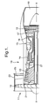
Figure 1 is a sectional side view of the upper half of a gas turbine engine; -
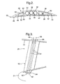
Figure 2 is a sectional plan view of an outlet guide vane according to the invention; and -
Figure 3 is a sectional side view of the outlet guide vane ofFigure 2 . - Referring first to
Figure 1 , a gas turbine engine generally indicated at 10 has a principal axis X-X. It comprises, in axial flow series, anair intake 11, apropulsive fan 12, anintermediate pressure compressor 13, ahigh pressure compressor 14, acombustor 15, ahigh pressure turbine 16, anintermediate pressure turbine 17, alow pressure turbine 18 and anexhaust nozzle 19. - The
gas turbine engine 10 works in a conventional manner so that air entering theintake 11 is accelerated by thefan 12. The accelerated air flow is split by the annularinner ring 21 into two air flows: a first air flow into theintermediate pressure compressor 13 and a second air flow which provides propulsive thrust. - The second air flow is directed through a flow passage defined by the
inner ring 21 and theannular fan casing 23, and flows through an annular array of fan outlet guide vanes (OGVs) 25. As well as guiding the second air flow, the OGVs provide (at least in three-shaft engines) a structural link between theengine core 27 and thefan casing 23. - The
intermediate pressure compressor 13 compresses the first air flow directed into it before delivering that air to thehigh pressure compressor 14 where further compression takes place. - The compressed air exhausted from the
high pressure compressor 14 is directed into thecombustor 15 where it is mixed with fuel and the mixture combusted. The resultant hot combustion products then expand through, and thereby drive, the high, intermediate andlow pressure turbines nozzle 19 to provide additional propulsive thrust. The high, intermediate andlow pressure turbines intermediate pressure compressors fan 12 by suitable interconnecting shafts. - Referring now to
Figure 2 , avane 25 according to the invention has an internal structural member comprising three metaltubular members 32. These are welded together along their lines ofcontact 34. In use, a vane assembly will comprise a plurality of such internal structural members each secured at its ends to theinner ring 21 and to thefan casing 23, as will be explained in more detail later. - Two
surface members tubular members 32, and are secured to each other by means of interlocking features 40, 42, 44. This also provides positive location of the surface members with respect to the internal structural member. Thesurface members inner ring 21 or to thefan casing 23, and so in use effectively all the loads between theinner ring 21 and thefan casing 23 are transmitted by the internal structural members of the plurality of vanes, and not by the surface members. The surface members do carry and react gas loads. - A leading
edge member 46 is secured between thesurface members features 48, and defines a leadingedge 50 of thevane 25. The leadingedge member 46 is made of metal, which provides greater resistance to erosion and foreign object damage in service. - The
surface members stiffening ribs 52 to provide greater mechanical integrity. - The
surface members spaces vane 25. With suitable design of the surrounding structures, one or both of thesespaces vane 25. Ejection holes for this air could be pre-moulded in the surface members. - The
tubular members 32 are hollow. With suitable design of the surrounding structures, one or more of thesetubular members 32 may be used as a fluid conduit for oil or for air to supply the engine internal air systems. -
Figure 3 shows a side sectional view of the vane ofFigure 2 . The leadingedge 50 of thevane 25, and the threetubular members 32, are clearly seen. Thevane 25 extends, as shown inFigure 1 , between theinner ring 21 and thefan casing 23. - The
vane 25 is secured to theinner ring 21 by twobolts 62, which pass through aload spreading plate 64. Thevane 25 is likewise secured to thefan casing 23 by twobolts 66, which pass through aload spreading plate 68. On assembly, the degree of tightening of thebolts 66 on the different vanes in the assembly may be adjusted to ensure that thefan casing 23 assumes its correct circular shape. - The
load spreading plates - The invention also offers advantages in those circumstances where cyclic stagger and camber is to be used on some vanes. The internal structural members can be of whatever configuration is required, and surface members of different aerodynamic standards can be readily attached where they are needed. These surface members may be differently coloured, or otherwise distinguished, to enable quick identification of the vanes that incorporate the aerodynamic variation.
- It will be appreciated by the skilled reader that other modifications and variations may be made to the embodiment described in this specification, without departing from the claimed invention.
- For example, the internal structural member of the
vane 25 may be constructed from rods, wires, cables, pipes, ducts, bars or any other suitably shaped members instead of tubular members. Fewer or moresuch members 32 than the three described may be used. All of the members need not be of the same form, and they may have different cross-sectional areas. Other materials besides metal may be used. - The aerofoil described is defined by two
surface members edge member 46, but it may be made up from a different number of surface members. Thesurface members - The surface members may be made from any suitable material. They may for example be metal, plastic or composite, or may comprise a flexible membrane stretched over a frame. The surface members may be made by any method appropriate for the material in question.
- The interlocking
members surface members - The interlocking members may act to secure the surface members only to each other. Alternatively or additionally, the interlocking members may secure one or more of the surface members to the internal structural member.
- Lugs or other features may be included in the interlocking members to provide radial location of the surface members, relative to each other or relative to the internal structural member.
- In certain embodiments, the internal structural member may extend outwards to form part of the aerofoil surface. In such cases, the surface members defining the front and rear parts of the aerofoil surface will necessarily be separate, and each will attach separately to the internal structural member.
- The
leading edge member 46, instead of being a separate component, may be an integral part of a surface member. - In certain applications the stiffening
ribs 52 may not be required. - Depending on the configuration of the surface members and the internal structural member, fewer or
more spaces 54 may be defined within thevanes 25, or there may be no spaces at all. - The invention has been described with reference to a fan outlet guide vane for a gas turbine engine. However, it will be appreciated that the principles of the invention may equally well be applied to other stationary components in the flow paths of gas turbine engines; for example, for the engine section stator or for other supports, whether in the bypass duct or in the core.
Claims (17)
- A vane (25) for a gas turbine engine, the vane comprising an internal structural member (32) and at least one surface member securable in use to the internal structural member so as to define an aerofoil.
- A vane as in claim 1, and comprising a plurality of surface members (36, 38) which are secured together in use and cooperate to define the aerofoil.
- A vane as in claim 2, in which the surface members are secured together in use by interlocking features (40, 42, 44) provided on their respective surfaces.
- A vane as in claim 3, in which interlocking features are also provided on the internal structural member.
- A vane as in any preceding claim, and further comprising a leading edge member (50), the leading edge members associated with the surface member or surface members so as to define in use a leading edge portion of the aerofoil.
- A vane as in claim 5, in which the leading edge member is secured in use to at least one surface member by interlocking features provided on their respective surfaces.
- A vane as in any preceding claim, in which the internal structural member comprises a plurality of tubular support members.
- A vane as in any preceding claim, in which the internal structural member comprises a plurality of metal tubes secured together.
- A vane as in any preceding claim, in which at least one surface member includes one or more strengthening ribs.
- A vane as in any preceding claim, in which the surface members when secured around the internal structural member define a space (54, 56), and the space serves in use as a conduit for anti-icing air.
- A vane as in claim 10, in which ejection holes for the anti-icing air are provided in at least one surface member.
- A vane as in any of claims 7 to 11, in which at least one tube of the internal structural member serves in use as a fluid conduit.
- A vane arrangement for a gas turbine engine, the engine including first structure (21) and second structure (23) together defining a duct, the arrangement including a vane as in any preceding claim, in which the internal structural member is secured in use to the first and second structure.
- A vane arrangement as in claim 13, in which the internal structural member is bolted to the first and second structures.
- A vane arrangement as in claim 13 or claim 14, in which the degree of tightening of the bolts can be altered to adjust the shape of the second structure.
- A vane assembly for a gas turbine engine, the assembly comprising a plurality of vane arrangements as in any of claims 13 to 15.
- A vane assembly as in claim 16, in which the aerofoil of at least one vane has a stagger and/or camber different from the other aerofoils.
Applications Claiming Priority (1)
| Application Number | Priority Date | Filing Date | Title |
|---|---|---|---|
| GBGB0719786.6A GB0719786D0 (en) | 2007-10-11 | 2007-10-11 | A vane and a vane assembly for a gas turbine engine |
Publications (3)
| Publication Number | Publication Date |
|---|---|
| EP2048325A2 true EP2048325A2 (en) | 2009-04-15 |
| EP2048325A3 EP2048325A3 (en) | 2013-08-07 |
| EP2048325B1 EP2048325B1 (en) | 2018-01-03 |
Family
ID=38787928
Family Applications (1)
| Application Number | Title | Priority Date | Filing Date |
|---|---|---|---|
| EP08253007.2A Not-in-force EP2048325B1 (en) | 2007-10-11 | 2008-09-11 | A vane and a vane assembly for a gas turbine engine |
Country Status (3)
| Country | Link |
|---|---|
| US (1) | US8100634B2 (en) |
| EP (1) | EP2048325B1 (en) |
| GB (1) | GB0719786D0 (en) |
Cited By (3)
| Publication number | Priority date | Publication date | Assignee | Title |
|---|---|---|---|---|
| US20110085895A1 (en) * | 2009-10-09 | 2011-04-14 | Pratt & Whitney Canada Corp. | Oil tube with integrated heat shield |
| FR3010132A1 (en) * | 2013-09-04 | 2015-03-06 | Safran | WAVE METAL ATTACK EDGE IN COMPOSITE MATERIAL FOR GAS TURBINE ENGINE |
| EP2365199A3 (en) * | 2010-03-10 | 2015-05-13 | Rolls-Royce Deutschland Ltd & Co KG | Aerodynamically shaped support and/or cladding element in the bypass of a gas turbine engine |
Families Citing this family (14)
| Publication number | Priority date | Publication date | Assignee | Title |
|---|---|---|---|---|
| US8162603B2 (en) * | 2009-01-30 | 2012-04-24 | General Electric Company | Vane frame for a turbomachine and method of minimizing weight thereof |
| US8696311B2 (en) | 2011-03-29 | 2014-04-15 | Pratt & Whitney Canada Corp. | Apparatus and method for gas turbine engine vane retention |
| US9068476B2 (en) | 2011-12-22 | 2015-06-30 | Pratt & Whitney Canada Corp. | Hybrid metal/composite link rod for turbofan gas turbine engine |
| US9121284B2 (en) * | 2012-01-27 | 2015-09-01 | United Technologies Corporation | Modal tuning for vanes |
| WO2014018137A2 (en) | 2012-04-25 | 2014-01-30 | General Electric Company | Aircraft engine driveshaft vessel assembly and method of assembling the same |
| US9441496B2 (en) | 2012-09-26 | 2016-09-13 | United Technologies Corporation | Structural guide vane internal topology |
| US9506361B2 (en) | 2013-03-08 | 2016-11-29 | Pratt & Whitney Canada Corp. | Low profile vane retention |
| US9726029B2 (en) * | 2013-07-18 | 2017-08-08 | Hamilton Sundstrand Corporation | Fluid cooling arrangement for a gas turbine engine and method |
| CN107542500B (en) * | 2017-09-30 | 2019-05-24 | 中国航发沈阳发动机研究所 | Aerial engine fan casing and its assembly method |
| FR3078367B1 (en) * | 2018-02-23 | 2021-09-03 | Safran Aircraft Engines | TURBOMACHINE WITH A HEAT EXCHANGER IN THE SECONDARY VEIN |
| GB201817153D0 (en) | 2018-10-22 | 2018-12-05 | Rolls Royce Plc | Gas turbine engine |
| US11585274B2 (en) * | 2020-12-28 | 2023-02-21 | General Electric Company | Turbine rear frame link assemblies for turbofan engines |
| US12331684B2 (en) * | 2023-11-07 | 2025-06-17 | Rtx Corporation | Strut microtube counterflow evaporator |
| US20260009340A1 (en) * | 2024-07-08 | 2026-01-08 | Rtx Corporation | Fan guide vane with leading edge deicing |
Citations (2)
| Publication number | Priority date | Publication date | Assignee | Title |
|---|---|---|---|---|
| US4786234A (en) | 1982-06-21 | 1988-11-22 | Teledyne Industries, Inc. | Turbine airfoil |
| EP0298898A2 (en) | 1987-07-09 | 1989-01-11 | United Technologies Corporation | Crossed I-beam structural strut |
Family Cites Families (11)
| Publication number | Priority date | Publication date | Assignee | Title |
|---|---|---|---|---|
| US3767322A (en) | 1971-07-30 | 1973-10-23 | Westinghouse Electric Corp | Internal cooling for turbine vanes |
| US4802823A (en) | 1988-05-09 | 1989-02-07 | Avco Corporation | Stress relief support structures and assemblies |
| US4993918A (en) * | 1989-05-19 | 1991-02-19 | United Technologies Corporation | Replaceable fairing for a turbine exhaust case |
| DD286016A5 (en) | 1989-07-21 | 1991-01-10 | Bergmann Borsig Veb | DUESENSCHAUFEL FOR STEAM OR GAS TURBINES |
| US5358379A (en) | 1993-10-27 | 1994-10-25 | Westinghouse Electric Corporation | Gas turbine vane |
| WO1998031922A1 (en) | 1997-01-14 | 1998-07-23 | Siemens Aktiengesellschaft | Turbine blade for a turbine engine, specially a gas turbine engine |
| EP1283326B1 (en) * | 2001-08-09 | 2005-12-21 | Siemens Aktiengesellschaft | Cooling of a turbine vane |
| US7093359B2 (en) | 2002-09-17 | 2006-08-22 | Siemens Westinghouse Power Corporation | Composite structure formed by CMC-on-insulation process |
| US7410342B2 (en) | 2005-05-05 | 2008-08-12 | Florida Turbine Technologies, Inc. | Airfoil support |
| US7322796B2 (en) | 2005-08-31 | 2008-01-29 | United Technologies Corporation | Turbine vane construction |
| US7648336B2 (en) * | 2006-01-03 | 2010-01-19 | General Electric Company | Apparatus and method for assembling a gas turbine stator |
-
2007
- 2007-10-11 GB GBGB0719786.6A patent/GB0719786D0/en not_active Ceased
-
2008
- 2008-09-11 EP EP08253007.2A patent/EP2048325B1/en not_active Not-in-force
- 2008-09-12 US US12/232,238 patent/US8100634B2/en not_active Expired - Fee Related
Patent Citations (2)
| Publication number | Priority date | Publication date | Assignee | Title |
|---|---|---|---|---|
| US4786234A (en) | 1982-06-21 | 1988-11-22 | Teledyne Industries, Inc. | Turbine airfoil |
| EP0298898A2 (en) | 1987-07-09 | 1989-01-11 | United Technologies Corporation | Crossed I-beam structural strut |
Cited By (4)
| Publication number | Priority date | Publication date | Assignee | Title |
|---|---|---|---|---|
| US20110085895A1 (en) * | 2009-10-09 | 2011-04-14 | Pratt & Whitney Canada Corp. | Oil tube with integrated heat shield |
| US8596959B2 (en) * | 2009-10-09 | 2013-12-03 | Pratt & Whitney Canada Corp. | Oil tube with integrated heat shield |
| EP2365199A3 (en) * | 2010-03-10 | 2015-05-13 | Rolls-Royce Deutschland Ltd & Co KG | Aerodynamically shaped support and/or cladding element in the bypass of a gas turbine engine |
| FR3010132A1 (en) * | 2013-09-04 | 2015-03-06 | Safran | WAVE METAL ATTACK EDGE IN COMPOSITE MATERIAL FOR GAS TURBINE ENGINE |
Also Published As
| Publication number | Publication date |
|---|---|
| EP2048325A3 (en) | 2013-08-07 |
| US20090097963A1 (en) | 2009-04-16 |
| US8100634B2 (en) | 2012-01-24 |
| GB0719786D0 (en) | 2007-11-21 |
| EP2048325B1 (en) | 2018-01-03 |
Similar Documents
| Publication | Publication Date | Title |
|---|---|---|
| US8100634B2 (en) | Vane and a vane assembly for a gas turbine engine | |
| US8092163B2 (en) | Turbine stator mount | |
| CN108930564B (en) | Cross-turbine engine air bearing and method of operation | |
| CN108952843B (en) | Cooling structure and thermal management method of cross-turbine engine air bearing | |
| CN108930594B (en) | Air bearing and thermal management nozzle arrangement for a cross-turbine engine | |
| US8172522B2 (en) | Method and system for supporting stator components | |
| CN106050314B (en) | Turbine frame and airfoil for turbine frame | |
| CN108930563B (en) | Method and structure for cross-turbine engine thermal management | |
| EP3524779B1 (en) | Tail bearing housing | |
| US10221712B2 (en) | Seal for hardware segments | |
| US11629602B2 (en) | Cooling schemes for airfoils for gas turbine engines | |
| US20170159487A1 (en) | HT Enhancement Bumps/Features on Cold Side | |
| CA2660179C (en) | A system and method for supporting stator components | |
| WO2017204949A1 (en) | Fuel delivery system for a gas turbine engine | |
| US20150369077A1 (en) | Suction-based active clearance control system | |
| EP1609954B1 (en) | Securing arrangement | |
| EP3514332A1 (en) | Dual-wall impingement cavity for components of gas turbine engines | |
| EP0580583B1 (en) | A combustion chamber assembly | |
| US11828226B2 (en) | Compressor bleed air channels having a pattern of vortex generators | |
| EP3159503B1 (en) | Compressor bleeding arrangement for a gas turbine and method of manufacturing a compressor section for a gas turbine | |
| CN105736149B (en) | There are conduit cover support members for gas-turbine unit | |
| EP1217231B1 (en) | Bolted joint for rotor disks and method of reducing thermal gradients therein | |
| US20140334925A1 (en) | System for supporting a turbine nozzle | |
| CN112302730B (en) | Turbine engine with interlocking seals | |
| JP6956497B2 (en) | Transition duct assembly |
Legal Events
| Date | Code | Title | Description |
|---|---|---|---|
| PUAI | Public reference made under article 153(3) epc to a published international application that has entered the european phase |
Free format text: ORIGINAL CODE: 0009012 |
|
| AK | Designated contracting states |
Kind code of ref document: A2 Designated state(s): AT BE BG CH CY CZ DE DK EE ES FI FR GB GR HR HU IE IS IT LI LT LU LV MC MT NL NO PL PT RO SE SI SK TR |
|
| AX | Request for extension of the european patent |
Extension state: AL BA MK RS |
|
| PUAL | Search report despatched |
Free format text: ORIGINAL CODE: 0009013 |
|
| RIC1 | Information provided on ipc code assigned before grant |
Ipc: F01D 9/04 20060101ALI20130627BHEP Ipc: F01D 5/14 20060101AFI20130627BHEP Ipc: F01D 9/06 20060101ALI20130627BHEP |
|
| AK | Designated contracting states |
Kind code of ref document: A3 Designated state(s): AT BE BG CH CY CZ DE DK EE ES FI FR GB GR HR HU IE IS IT LI LT LU LV MC MT NL NO PL PT RO SE SI SK TR |
|
| AX | Request for extension of the european patent |
Extension state: AL BA MK RS |
|
| 17P | Request for examination filed |
Effective date: 20140207 |
|
| AKX | Designation fees paid |
Designated state(s): DE FR GB |
|
| RAP1 | Party data changed (applicant data changed or rights of an application transferred) |
Owner name: ROLLS-ROYCE PLC |
|
| GRAP | Despatch of communication of intention to grant a patent |
Free format text: ORIGINAL CODE: EPIDOSNIGR1 |
|
| STAA | Information on the status of an ep patent application or granted ep patent |
Free format text: STATUS: GRANT OF PATENT IS INTENDED |
|
| GRAS | Grant fee paid |
Free format text: ORIGINAL CODE: EPIDOSNIGR3 |
|
| INTG | Intention to grant announced |
Effective date: 20171030 |
|
| GRAA | (expected) grant |
Free format text: ORIGINAL CODE: 0009210 |
|
| STAA | Information on the status of an ep patent application or granted ep patent |
Free format text: STATUS: THE PATENT HAS BEEN GRANTED |
|
| AK | Designated contracting states |
Kind code of ref document: B1 Designated state(s): DE FR GB |
|
| REG | Reference to a national code |
Ref country code: GB Ref legal event code: FG4D |
|
| REG | Reference to a national code |
Ref country code: DE Ref legal event code: R096 Ref document number: 602008053573 Country of ref document: DE |
|
| REG | Reference to a national code |
Ref country code: FR Ref legal event code: PLFP Year of fee payment: 11 |
|
| REG | Reference to a national code |
Ref country code: DE Ref legal event code: R097 Ref document number: 602008053573 Country of ref document: DE |
|
| PLBE | No opposition filed within time limit |
Free format text: ORIGINAL CODE: 0009261 |
|
| STAA | Information on the status of an ep patent application or granted ep patent |
Free format text: STATUS: NO OPPOSITION FILED WITHIN TIME LIMIT |
|
| 26N | No opposition filed |
Effective date: 20181005 |
|
| PGFP | Annual fee paid to national office [announced via postgrant information from national office to epo] |
Ref country code: FR Payment date: 20190925 Year of fee payment: 12 |
|
| PGFP | Annual fee paid to national office [announced via postgrant information from national office to epo] |
Ref country code: GB Payment date: 20190927 Year of fee payment: 12 |
|
| PGFP | Annual fee paid to national office [announced via postgrant information from national office to epo] |
Ref country code: DE Payment date: 20190927 Year of fee payment: 12 |
|
| REG | Reference to a national code |
Ref country code: DE Ref legal event code: R119 Ref document number: 602008053573 Country of ref document: DE |
|
| GBPC | Gb: european patent ceased through non-payment of renewal fee |
Effective date: 20200911 |
|
| PG25 | Lapsed in a contracting state [announced via postgrant information from national office to epo] |
Ref country code: DE Free format text: LAPSE BECAUSE OF NON-PAYMENT OF DUE FEES Effective date: 20210401 Ref country code: FR Free format text: LAPSE BECAUSE OF NON-PAYMENT OF DUE FEES Effective date: 20200930 |
|
| PG25 | Lapsed in a contracting state [announced via postgrant information from national office to epo] |
Ref country code: GB Free format text: LAPSE BECAUSE OF NON-PAYMENT OF DUE FEES Effective date: 20200911 |