EP2048308B1 - Device for hinging and supporting a vehicle bonnet - Google Patents
Device for hinging and supporting a vehicle bonnet Download PDFInfo
- Publication number
- EP2048308B1 EP2048308B1 EP07425634A EP07425634A EP2048308B1 EP 2048308 B1 EP2048308 B1 EP 2048308B1 EP 07425634 A EP07425634 A EP 07425634A EP 07425634 A EP07425634 A EP 07425634A EP 2048308 B1 EP2048308 B1 EP 2048308B1
- Authority
- EP
- European Patent Office
- Prior art keywords
- bonnet
- bracket
- lever mechanism
- toggle lever
- axis
- Prior art date
- Legal status (The legal status is an assumption and is not a legal conclusion. Google has not performed a legal analysis and makes no representation as to the accuracy of the status listed.)
- Not-in-force
Links
Images


Classifications
-
- E—FIXED CONSTRUCTIONS
- E05—LOCKS; KEYS; WINDOW OR DOOR FITTINGS; SAFES
- E05D—HINGES OR SUSPENSION DEVICES FOR DOORS, WINDOWS OR WINGS
- E05D3/00—Hinges with pins
- E05D3/06—Hinges with pins with two or more pins
- E05D3/14—Hinges with pins with two or more pins with four parallel pins and two arms
- E05D3/145—Hinges with pins with two or more pins with four parallel pins and two arms specially adapted for vehicles
-
- E—FIXED CONSTRUCTIONS
- E05—LOCKS; KEYS; WINDOW OR DOOR FITTINGS; SAFES
- E05D—HINGES OR SUSPENSION DEVICES FOR DOORS, WINDOWS OR WINGS
- E05D11/00—Additional features or accessories of hinges
- E05D11/10—Devices for preventing movement between relatively-movable hinge parts
- E05D11/1028—Devices for preventing movement between relatively-movable hinge parts for maintaining the hinge in two or more positions, e.g. intermediate or fully open
- E05D11/105—Devices for preventing movement between relatively-movable hinge parts for maintaining the hinge in two or more positions, e.g. intermediate or fully open the maintaining means acting perpendicularly to the pivot axis
- E05D11/1064—Devices for preventing movement between relatively-movable hinge parts for maintaining the hinge in two or more positions, e.g. intermediate or fully open the maintaining means acting perpendicularly to the pivot axis with a coil spring perpendicular to the pivot axis
- E05D11/1071—Devices for preventing movement between relatively-movable hinge parts for maintaining the hinge in two or more positions, e.g. intermediate or fully open the maintaining means acting perpendicularly to the pivot axis with a coil spring perpendicular to the pivot axis specially adapted for vehicles
-
- E—FIXED CONSTRUCTIONS
- E05—LOCKS; KEYS; WINDOW OR DOOR FITTINGS; SAFES
- E05Y—INDEXING SCHEME ASSOCIATED WITH SUBCLASSES E05D AND E05F, RELATING TO CONSTRUCTION ELEMENTS, ELECTRIC CONTROL, POWER SUPPLY, POWER SIGNAL OR TRANSMISSION, USER INTERFACES, MOUNTING OR COUPLING, DETAILS, ACCESSORIES, AUXILIARY OPERATIONS NOT OTHERWISE PROVIDED FOR, APPLICATION THEREOF
- E05Y2900/00—Application of doors, windows, wings or fittings thereof
- E05Y2900/50—Application of doors, windows, wings or fittings thereof for vehicles
- E05Y2900/53—Type of wing
- E05Y2900/531—Doors
-
- E—FIXED CONSTRUCTIONS
- E05—LOCKS; KEYS; WINDOW OR DOOR FITTINGS; SAFES
- E05Y—INDEXING SCHEME ASSOCIATED WITH SUBCLASSES E05D AND E05F, RELATING TO CONSTRUCTION ELEMENTS, ELECTRIC CONTROL, POWER SUPPLY, POWER SIGNAL OR TRANSMISSION, USER INTERFACES, MOUNTING OR COUPLING, DETAILS, ACCESSORIES, AUXILIARY OPERATIONS NOT OTHERWISE PROVIDED FOR, APPLICATION THEREOF
- E05Y2900/00—Application of doors, windows, wings or fittings thereof
- E05Y2900/50—Application of doors, windows, wings or fittings thereof for vehicles
- E05Y2900/53—Type of wing
- E05Y2900/536—Hoods
Definitions
- the present invention relates to a device for hinging and supporting a vehicle bonnet, according to the first part of claim 1 (see document US-A-3815176 ).
- a bonnet On vehicles, particularly motor vehicles, the use of a bonnet is known, in particular an engine bonnet, which pivots in relation to the body of the vehicle about a horizontal hinge axis between an open position and a closed position.
- a supporting device is provided to hold the bonnet in the open position.
- the supporting device normally comprises a rod, which is hinged at one end thereof to the body of the vehicle and is moved manually between a rest position, in which the rod is arranged in a substantially horizontal position and is releasably blocked by means of a snap mechanism on the body, and an operating position, in which the rod is arranged in a raised position and has an upper end that supports the bonnet in the open position.
- the purpose of the present invention is to provide a device for hinging and supporting a vehicle bonnet, which overcomes the drawbacks described above in a simple and cost-effective manner.
- a device for hinging and supporting a vehicle bonnet comprising:
- reference number 1 indicates a hinging and supporting device to couple a bonnet 2, in particular an engine bonnet (partially and schematically illustrated by means of the dashed line) to a body 3 of a vehicle, in particular a motor vehicle.
- the device 1 comprises a bracket 4, which is fixed to the body 3, consists of a single piece, and comprises three walls 9,10,11 which are joined together.
- the wall 9 defines a substantially horizontal base; the wall 10 is substantially vertical and is at the rear, i.e. it faces a passenger compartment of the vehicle; and the wall 11 is arranged laterally and is also substantially vertical.
- the bracket 4 also comprises an appendix 12, extending in a cantilevered fashion from the upper end of the wall 10 in a position facing the wall 11; and a stop element 13 ( Figure 2 ), extending in a cantilevered fashion from an intermediate front portion 14 of the wall 11 in a position facing the walls 9 and 10.
- the device 1 comprises a bracket 15, which comprises two end portions 16 and 17 arranged opposite one another and coupled to the bonnet 2 and, respectively, to the bracket 4.
- the portion 16 is directly fixed to a lower surface of the bonnet 2, while the portion 17 is directly hinged to an upper end 18 of the wall 11 to pivot about a horizontal axis 19, which is fixed in relation to the body 3, and thus make the bonnet 2 pivot between a closed lowered position and an open raised position.
- the portion 17 is substantially rectilinear, it is joined to an intermediate portion 20 of the bracket 15 via a curved portion 21, and has a slit 22 ( Figure 3 ) that is engaged by the appendix 12 when the bonnet 2 is arranged in the closed lowered position.
- the device 1 comprises a toggle lever system 23, which consists of an upper lever 24 and a lower lever 25 having respective plate shaped end portions 26 and 27 that are hinged about an axis 29.
- the axis 29 is parallel to the axis 19, and fixed in relation to each of the levers 24 and 25, and is able to move from and towards the axis 19 during the closing and, respectively, opening of the bonnet 2.
- the lever 24 has an upper end 30 ( Figure 1 ), which is opposite the portion 26 and is directly hinged to the portion 20 of the bracket 15 about an axis 31.
- the axis 31 is parallel to the axes 19 and 29 and is fixed in relation to each of the levers 5 and 24.
- the lever 25 has a lower end 33, which is opposite the portion 27 and is directly hinged to a lower and front portion 34 of the wall 11 about an axis 35.
- the axis 35 is also parallel to the axes 19 and 29 and fixed with respect to the lever 25 and the bracket 4.
- the portions 26 and 30 of the lever 24 are staggered in relation to one another in a direction parallel to the axes 29 and 31 and are joined together by means of a transversal portion 36 which faces the bracket 15 in a direction at right angles to the axis 19. Therefore, the portions 26 and 27 and, thus, the hinge defined by the axis 29 are aligned vertically with the bracket 15.
- the lever 24 also comprises a tab 37, which extends in a cantilevered fashion from the portion 26 in a position facing the bracket 15 and defines a grip portion for a user, to manually push the toggle lever mechanism 23 from a first operating position, corresponding to the open raised position of the bonnet 2, against the force exerted by a spring 38.
- the spring 38 is of the coil type and the ends of said spring are hooked to the wall 10 of the bracket 4 and, respectively, to the portion 27 of the lever 25.
- the toggle lever mechanism 23 In the first operating position, the toggle lever mechanism 23 is arranged in the end-of-travel position, resting against the stop element 13 in a direction substantially parallel to the force exerted by the spring 38. In this way, the toggle lever mechanism 23 supports the bonnet 2 in the open raised position.
- an intermediate portion 39 of the lever 25 has a hollowed rear edge 40 that is engaged by the stop element 13.
- the portion 36 is arranged in a position adjacent to the portion 21.
- the toggle lever mechanism 23 When the bonnet 2 is arranged in the closed lowered position, the toggle lever mechanism 23 is arranged in a second operating position, in which the axis 29 is further away from the axis 19. During the movement between the two operating positions, the toggle lever mechanism 23 moves beyond a dead center position, in which the axes 29, 31 and 35 are aligned in relation to one another and, thus, the bonnet 2 is raised to the maximum height allowed by the toggle lever mechanism 23.
- the tab 37 must be operated manually to move the toggle lever mechanism 23 away from the first operating position, by raising the bonnet 2 slightly with respect to the raised open position, and then to move beyond the dead center position. Once the dead center position has been passed, the bonnet 2 can simply be allowed to lower itself due to the effect of its weight in order to move the toggle lever mechanism 23 back to and hold it in the second operating position.
- the appendix 12 engages the slit 22 in order to block the bracket 15 in case the hinge defined by the axis 19 should give way during a collision or accident.
- the device 1 holds the bonnet 2 in the raised position in a simple manner, with a relatively small number of components and limited overall dimensions.
- the device 1 has the function of making the bonnet 2 pivot by means of the hinge defined by the axis 19, and also the function of keeping the bonnet 2 blocked in the open raised position.
- the device 1 holds the bonnet 2 open without obstructing the engine compartment laterally, thus making the engine compartment more accessible for servicing, in that the toggle lever mechanism 23 is connected directly to the brackets 4 and 15.
- the operations to move the bonnet 2 to the open raised position are simple, in that the toggle lever mechanism 23 moves to its first operating position automatically, thanks to the spring 38.
- the device 1 is also relatively cheap and relatively light.
- the end-of-travel surface for the first operating position of the toggle lever mechanism 23 could be defined directly by a portion of the bracket 4, and/or could be provided by the bracket 15, and/or could support the lever 24 with or instead of the lever 25.
- the axes 29, 31 and 35 while parallel to one another, need not be parallel to the axis 19 and/or may be defined by ball joints.
- the spring 38 could be of a different type, for example it could be a torsion spring arranged about the axes 29, 31 or 35, or it could be arranged in a different position with respect to that described by way of example.
Landscapes
- Engineering & Computer Science (AREA)
- Mechanical Engineering (AREA)
- Superstructure Of Vehicle (AREA)
- Body Structure For Vehicles (AREA)
Abstract
Description
- The present invention relates to a device for hinging and supporting a vehicle bonnet, according to the first part of claim 1 (see document
US-A-3815176 ). - On vehicles, particularly motor vehicles, the use of a bonnet is known, in particular an engine bonnet, which pivots in relation to the body of the vehicle about a horizontal hinge axis between an open position and a closed position.
- At the same time, a supporting device is provided to hold the bonnet in the open position. The supporting device normally comprises a rod, which is hinged at one end thereof to the body of the vehicle and is moved manually between a rest position, in which the rod is arranged in a substantially horizontal position and is releasably blocked by means of a snap mechanism on the body, and an operating position, in which the rod is arranged in a raised position and has an upper end that supports the bonnet in the open position.
- Another solution is disclosed in European patent application
EP1719865 , which shows a pair of levers that are hinged to one another at one of their ends and hinged, at the opposite ends, respectively to the bonnet and to the body of the vehicle. When the bonnet is open, the two levers are held by a fixing mechanism in a position so that they are aligned with one another, acting as a stay to support the bonnet. To lower and close the bonnet, the fixing mechanism must be released manually using a Bowden cable. - While eliminating the need for a rod that must be raised manually when opening the bonnet, the solution known in the prior art described above makes closing the bonnet a relatively complex operation and comprises a relatively large number of components.
- Moreover, when the bonnet is open, the position of the normal supporting rod or the position of the arms described in
EP1719865 laterally limits the amount of space available for maneuvering when carrying out maintenance in the engine compartment. - The purpose of the present invention is to provide a device for hinging and supporting a vehicle bonnet, which overcomes the drawbacks described above in a simple and cost-effective manner.
- According to the present invention a device for hinging and supporting a vehicle bonnet is provided, said device comprising:
- a first bracket suitable to be fixed to said bonnet;
- a second bracket suitable to be fixed to a body of the vehicle and directly hinged to said first bracket about a substantially horizontal axis of rotation in order to allow said bonnet to pivot between a raised position and a lowered position;
- supporting means able to move between a first operating position, in which they support said bonnet in the raised position, and a second operating position, corresponding to the lowered position of said bonnet;
- The present invention will now be described with reference to the attached drawings, illustrating a nonlimiting embodiment thereof, in which:
-
Figure 1 shows a perspective view of a preferred embodiment of the device for hinging and supporting a vehicle bonnet according to the present invention; -
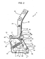
Figure 2 shows the device inFigure 1 from a different perspective and in a larger scale; -
Figure 3 is similar toFigure 2 and shows the device in a different operating position. - In
Figure 1 ,reference number 1 indicates a hinging and supporting device to couple a bonnet 2, in particular an engine bonnet (partially and schematically illustrated by means of the dashed line) to abody 3 of a vehicle, in particular a motor vehicle. - The
device 1 comprises abracket 4, which is fixed to thebody 3, consists of a single piece, and comprises threewalls wall 9 defines a substantially horizontal base; thewall 10 is substantially vertical and is at the rear, i.e. it faces a passenger compartment of the vehicle; and thewall 11 is arranged laterally and is also substantially vertical. Thebracket 4 also comprises anappendix 12, extending in a cantilevered fashion from the upper end of thewall 10 in a position facing thewall 11; and a stop element 13 (Figure 2 ), extending in a cantilevered fashion from anintermediate front portion 14 of thewall 11 in a position facing thewalls - The
device 1 comprises abracket 15, which comprises twoend portions bracket 4. Theportion 16 is directly fixed to a lower surface of the bonnet 2, while theportion 17 is directly hinged to anupper end 18 of thewall 11 to pivot about ahorizontal axis 19, which is fixed in relation to thebody 3, and thus make the bonnet 2 pivot between a closed lowered position and an open raised position. - The
portion 17 is substantially rectilinear, it is joined to anintermediate portion 20 of thebracket 15 via acurved portion 21, and has a slit 22 (Figure 3 ) that is engaged by theappendix 12 when the bonnet 2 is arranged in the closed lowered position. - The
device 1 comprises atoggle lever system 23, which consists of anupper lever 24 and alower lever 25 having respective plate shapedend portions axis 29. Theaxis 29 is parallel to theaxis 19, and fixed in relation to each of thelevers axis 19 during the closing and, respectively, opening of the bonnet 2. - The
lever 24 has an upper end 30 (Figure 1 ), which is opposite theportion 26 and is directly hinged to theportion 20 of thebracket 15 about anaxis 31. Theaxis 31 is parallel to theaxes levers 5 and 24. Similarly, thelever 25 has alower end 33, which is opposite theportion 27 and is directly hinged to a lower andfront portion 34 of thewall 11 about anaxis 35. Theaxis 35 is also parallel to theaxes lever 25 and thebracket 4. - The
portions lever 24 are staggered in relation to one another in a direction parallel to theaxes transversal portion 36 which faces thebracket 15 in a direction at right angles to theaxis 19. Therefore, theportions axis 29 are aligned vertically with thebracket 15. Thelever 24 also comprises atab 37, which extends in a cantilevered fashion from theportion 26 in a position facing thebracket 15 and defines a grip portion for a user, to manually push thetoggle lever mechanism 23 from a first operating position, corresponding to the open raised position of the bonnet 2, against the force exerted by aspring 38. Thespring 38 is of the coil type and the ends of said spring are hooked to thewall 10 of thebracket 4 and, respectively, to theportion 27 of thelever 25. In the first operating position, thetoggle lever mechanism 23 is arranged in the end-of-travel position, resting against thestop element 13 in a direction substantially parallel to the force exerted by thespring 38. In this way, thetoggle lever mechanism 23 supports the bonnet 2 in the open raised position. In particular, anintermediate portion 39 of thelever 25 has a hollowedrear edge 40 that is engaged by thestop element 13. At the same time, theportion 36 is arranged in a position adjacent to theportion 21. - When the bonnet 2 is arranged in the closed lowered position, the
toggle lever mechanism 23 is arranged in a second operating position, in which theaxis 29 is further away from theaxis 19. During the movement between the two operating positions, thetoggle lever mechanism 23 moves beyond a dead center position, in which theaxes toggle lever mechanism 23. - When the bonnet 2 is pivoted manually in order to be opened, the
lever 25 is automatically raised due to the pulling force exerted by thespring 38 towards thebracket 4 and the upward force exerted by the bonnet 2 via thelever 24. When the bonnet 2 is raised with the maximum angle of rotation, thetoggle lever mechanism 23 is in the dead center position, but the force exerted by thespring 38 means this position is automatically exceeded. Subsequently, the force of thespring 38, combined with the weight of the bonnet 2 tend to move and hold thetoggle lever mechanism 23 in the first operating position. At this stage, the weight of the bonnet 2 is discharged by thebracket 15 onto thebracket 4 via the hinges of thelever mechanism 23 and via the support defined by thestop element 13, without the need for a manual support. - During the closing of the bonnet 2, however, the
tab 37 must be operated manually to move thetoggle lever mechanism 23 away from the first operating position, by raising the bonnet 2 slightly with respect to the raised open position, and then to move beyond the dead center position. Once the dead center position has been passed, the bonnet 2 can simply be allowed to lower itself due to the effect of its weight in order to move thetoggle lever mechanism 23 back to and hold it in the second operating position. - In the second operating position of the
toggle lever mechanism 23, theappendix 12 engages theslit 22 in order to block thebracket 15 in case the hinge defined by theaxis 19 should give way during a collision or accident. - From the above description it is clear that the
device 1 holds the bonnet 2 in the raised position in a simple manner, with a relatively small number of components and limited overall dimensions. - The
device 1 has the function of making the bonnet 2 pivot by means of the hinge defined by theaxis 19, and also the function of keeping the bonnet 2 blocked in the open raised position. In particular, thedevice 1 holds the bonnet 2 open without obstructing the engine compartment laterally, thus making the engine compartment more accessible for servicing, in that thetoggle lever mechanism 23 is connected directly to thebrackets - The solution is also made extremely simple by the presence of the dead center position and the end-of-travel position defined by the
stop element 13, which means there is no need for any additional blocking mechanisms to keep thelevers - Moreover, the operations to move the bonnet 2 to the open raised position are simple, in that the
toggle lever mechanism 23 moves to its first operating position automatically, thanks to thespring 38. Thedevice 1 is also relatively cheap and relatively light. - Lastly, from the above description, it is clear that modifications and variations may be made to the
device 1 described herein without departing from the scope of the present invention as set forth in the appended claims. - In particular, the end-of-travel surface for the first operating position of the
toggle lever mechanism 23 could be defined directly by a portion of thebracket 4, and/or could be provided by thebracket 15, and/or could support thelever 24 with or instead of thelever 25. - Furthermore, the
axes axis 19 and/or may be defined by ball joints. - Lastly, the
spring 38 could be of a different type, for example it could be a torsion spring arranged about theaxes
Claims (8)
- Device (1) for hinging and supporting a vehicle bonnet (2), said device comprising:- a first bracket (15) suitable to be fixed to said bonnet (2);- a second bracket (4) suitable to be fixed to a body (3) of the vehicle and pivotally connected to said first bracket (15) in order to allow said bonnet (2) to pivot between a raised position and a lowered position;- supporting means (23) able to move between a first operating position, in which they support said bonnet (2) in the raised position, and a second operating position, corresponding to the lowered position of said bonnet (2); whereinsaid supporting means comprise a toggle lever mechanism (23) consisting of a first (24) and a second (25) lever directly hinged to one another about a first hinge axis (29); said first lever (24) being directly hinged to said first bracket (15) about a second hinge axis (31) parallel to said first hinge axis (29); said second lever (25) being directly hinged to said second bracket (4) about a third hinge axis (35) parallel to said first hinge axis (29),
characterized in that said first bracket (15) is directly hinged to said second bracket (4) about a substantially horizontal axis of rotation (19). - Device according to claim 1, characterized in that said first and second operating positions of said toggle lever mechanism (23) are arranged on opposite sides of a dead center position, wherein said first, second and third hinge axes (29,31,35) are aligned in relation to one another.
- Device according to claim 2, characterized by comprising elastic means (38) which exert an elastic force in order to move said toggle lever mechanism (23) automatically towards said first operating position when said bonnet (2) is pivoted towards its raised position.
- Device according to claim 3, characterized in that said elastic means comprise a coil spring (38) having the ends hooked to said second bracket (4) and, respectively, to said second lever (25).
- Device according to any of the claims from 2 to 4, characterized by comprising stop means (13) provided by said second bracket (4) in a fixed position and defining an angular end-of-travel position for at least one of said first and second levers (24,25) in said first operating position.
- Device according to claim 5, characterized in that said stop means (13) define a support to carry the weight of said bonnet (2) which is discharged by said first bracket (15) onto said second bracket (4) via said toggle lever mechanism (23).
- Device according to any of the previous claims, characterized by comprising a grip portion (37) provided by one of said first and second levers (24,25) and which can be operated manually to pull said toggle lever mechanism (23) towards said second operating position.
- Device according to any of the previous claims, characterized in that said first, second and third hinge axes (29,31,35) and said axis of rotation (19) are parallel to one another.
Priority Applications (3)
| Application Number | Priority Date | Filing Date | Title |
|---|---|---|---|
| DE602007006503T DE602007006503D1 (en) | 2007-10-11 | 2007-10-11 | Device for holding and hinging a vehicle flap |
| EP07425634A EP2048308B1 (en) | 2007-10-11 | 2007-10-11 | Device for hinging and supporting a vehicle bonnet |
| AT07425634T ATE467741T1 (en) | 2007-10-11 | 2007-10-11 | DEVICE FOR HOLDING AND ARCHING A VEHICLE HATCH |
Applications Claiming Priority (1)
| Application Number | Priority Date | Filing Date | Title |
|---|---|---|---|
| EP07425634A EP2048308B1 (en) | 2007-10-11 | 2007-10-11 | Device for hinging and supporting a vehicle bonnet |
Publications (2)
| Publication Number | Publication Date |
|---|---|
| EP2048308A1 EP2048308A1 (en) | 2009-04-15 |
| EP2048308B1 true EP2048308B1 (en) | 2010-05-12 |
Family
ID=39113927
Family Applications (1)
| Application Number | Title | Priority Date | Filing Date |
|---|---|---|---|
| EP07425634A Not-in-force EP2048308B1 (en) | 2007-10-11 | 2007-10-11 | Device for hinging and supporting a vehicle bonnet |
Country Status (3)
| Country | Link |
|---|---|
| EP (1) | EP2048308B1 (en) |
| AT (1) | ATE467741T1 (en) |
| DE (1) | DE602007006503D1 (en) |
Family Cites Families (4)
| Publication number | Priority date | Publication date | Assignee | Title |
|---|---|---|---|---|
| DE1090542B (en) * | 1956-03-07 | 1960-10-06 | Ford Werke Ag | Hinge for the wing, especially of motor vehicle doors, with springs to push the wing into the end positions |
| US3815176A (en) * | 1973-08-02 | 1974-06-11 | Gen Motors Corp | Vehicle body hood hinge |
| DE102005006916B4 (en) * | 2005-02-16 | 2007-11-22 | Edscha Ag | Hinge for a vehicle flap |
| KR100689291B1 (en) | 2005-05-03 | 2007-03-02 | 볼보 컨스트럭션 이키프먼트 홀딩 스웨덴 에이비 | Fixing and releasing device of engine hood door |
-
2007
- 2007-10-11 EP EP07425634A patent/EP2048308B1/en not_active Not-in-force
- 2007-10-11 AT AT07425634T patent/ATE467741T1/en not_active IP Right Cessation
- 2007-10-11 DE DE602007006503T patent/DE602007006503D1/en active Active
Also Published As
| Publication number | Publication date |
|---|---|
| EP2048308A1 (en) | 2009-04-15 |
| DE602007006503D1 (en) | 2010-06-24 |
| ATE467741T1 (en) | 2010-05-15 |
Similar Documents
| Publication | Publication Date | Title |
|---|---|---|
| EP2392755B1 (en) | Lid opening and closing apparatus | |
| EP2044282B1 (en) | Integrated hinge assembly with spring biased prop arm | |
| EP2393684B1 (en) | A roof assembly for a vehicle | |
| US8245447B2 (en) | Slide door assembly with safety device | |
| EP2065545B1 (en) | Hood stay apparatus for engine room in heavy construction equipment | |
| US20100162847A1 (en) | Actuating mechanism for a pivotably mounted actuating arm | |
| US20090223263A1 (en) | Dual-member inertia-activated locking mechanism for vehicle door handle assembly | |
| JPH0769245A (en) | Vehicle hood | |
| EP1612354A2 (en) | Upper articulation assembly for turn and tilt window or door. | |
| US5791428A (en) | Locking reduced-effort hood control apparatus | |
| JP2001163060A (en) | Opening roof structure for vehicles | |
| EP2048308A1 (en) | Device for hinging and supporting a vehicle bonnet | |
| RU2428323C2 (en) | Flap roof lock and vehicle with said lock | |
| GB2413155A (en) | Hinge | |
| JP5631189B2 (en) | Operation mechanism and lock mechanism for vehicle cover | |
| US20020195828A1 (en) | Closure device | |
| JP5645639B2 (en) | Bearings for vehicle covers | |
| JP3664518B2 (en) | Hinge for flip-up door | |
| JP5064199B2 (en) | Car door lock device | |
| WO2002034558A1 (en) | Open roof construction for a vehicle | |
| US4833826A (en) | Closure device having a hinged closure member | |
| US20130088021A1 (en) | Vehicle Door Mechanism | |
| EP1944223B1 (en) | Vehicle bonnet | |
| JPH09177419A (en) | Switchgear for switchgear | |
| GB2302475A (en) | Movable device for holding a car telephone |
Legal Events
| Date | Code | Title | Description |
|---|---|---|---|
| PUAI | Public reference made under article 153(3) epc to a published international application that has entered the european phase |
Free format text: ORIGINAL CODE: 0009012 |
|
| 17P | Request for examination filed |
Effective date: 20081211 |
|
| AK | Designated contracting states |
Kind code of ref document: A1 Designated state(s): AT BE BG CH CY CZ DE DK EE ES FI FR GB GR HU IE IS IT LI LT LU LV MC MT NL PL PT RO SE SI SK TR |
|
| AX | Request for extension of the european patent |
Extension state: AL BA HR MK RS |
|
| GRAP | Despatch of communication of intention to grant a patent |
Free format text: ORIGINAL CODE: EPIDOSNIGR1 |
|
| AKX | Designation fees paid |
Designated state(s): AT BE BG CH CY CZ DE DK EE ES FI FR GB GR HU IE IS IT LI LT LU LV MC MT NL PL PT RO SE SI SK TR |
|
| GRAS | Grant fee paid |
Free format text: ORIGINAL CODE: EPIDOSNIGR3 |
|
| GRAA | (expected) grant |
Free format text: ORIGINAL CODE: 0009210 |
|
| AK | Designated contracting states |
Kind code of ref document: B1 Designated state(s): AT BE BG CH CY CZ DE DK EE ES FI FR GB GR HU IE IS IT LI LT LU LV MC MT NL PL PT RO SE SI SK TR |
|
| REG | Reference to a national code |
Ref country code: GB Ref legal event code: FG4D |
|
| REG | Reference to a national code |
Ref country code: CH Ref legal event code: EP |
|
| REG | Reference to a national code |
Ref country code: IE Ref legal event code: FG4D |
|
| REF | Corresponds to: |
Ref document number: 602007006503 Country of ref document: DE Date of ref document: 20100624 Kind code of ref document: P |
|
| REG | Reference to a national code |
Ref country code: NL Ref legal event code: VDEP Effective date: 20100512 |
|
| LTIE | Lt: invalidation of european patent or patent extension |
Effective date: 20100512 |
|
| PG25 | Lapsed in a contracting state [announced via postgrant information from national office to epo] |
Ref country code: NL Free format text: LAPSE BECAUSE OF FAILURE TO SUBMIT A TRANSLATION OF THE DESCRIPTION OR TO PAY THE FEE WITHIN THE PRESCRIBED TIME-LIMIT Effective date: 20100512 Ref country code: ES Free format text: LAPSE BECAUSE OF FAILURE TO SUBMIT A TRANSLATION OF THE DESCRIPTION OR TO PAY THE FEE WITHIN THE PRESCRIBED TIME-LIMIT Effective date: 20100823 Ref country code: LT Free format text: LAPSE BECAUSE OF FAILURE TO SUBMIT A TRANSLATION OF THE DESCRIPTION OR TO PAY THE FEE WITHIN THE PRESCRIBED TIME-LIMIT Effective date: 20100512 Ref country code: SE Free format text: LAPSE BECAUSE OF FAILURE TO SUBMIT A TRANSLATION OF THE DESCRIPTION OR TO PAY THE FEE WITHIN THE PRESCRIBED TIME-LIMIT Effective date: 20100512 |
|
| PG25 | Lapsed in a contracting state [announced via postgrant information from national office to epo] |
Ref country code: SI Free format text: LAPSE BECAUSE OF FAILURE TO SUBMIT A TRANSLATION OF THE DESCRIPTION OR TO PAY THE FEE WITHIN THE PRESCRIBED TIME-LIMIT Effective date: 20100512 Ref country code: LV Free format text: LAPSE BECAUSE OF FAILURE TO SUBMIT A TRANSLATION OF THE DESCRIPTION OR TO PAY THE FEE WITHIN THE PRESCRIBED TIME-LIMIT Effective date: 20100512 Ref country code: IS Free format text: LAPSE BECAUSE OF FAILURE TO SUBMIT A TRANSLATION OF THE DESCRIPTION OR TO PAY THE FEE WITHIN THE PRESCRIBED TIME-LIMIT Effective date: 20100912 Ref country code: FI Free format text: LAPSE BECAUSE OF FAILURE TO SUBMIT A TRANSLATION OF THE DESCRIPTION OR TO PAY THE FEE WITHIN THE PRESCRIBED TIME-LIMIT Effective date: 20100512 Ref country code: AT Free format text: LAPSE BECAUSE OF FAILURE TO SUBMIT A TRANSLATION OF THE DESCRIPTION OR TO PAY THE FEE WITHIN THE PRESCRIBED TIME-LIMIT Effective date: 20100512 |
|
| PG25 | Lapsed in a contracting state [announced via postgrant information from national office to epo] |
Ref country code: CY Free format text: LAPSE BECAUSE OF FAILURE TO SUBMIT A TRANSLATION OF THE DESCRIPTION OR TO PAY THE FEE WITHIN THE PRESCRIBED TIME-LIMIT Effective date: 20100609 Ref country code: PL Free format text: LAPSE BECAUSE OF FAILURE TO SUBMIT A TRANSLATION OF THE DESCRIPTION OR TO PAY THE FEE WITHIN THE PRESCRIBED TIME-LIMIT Effective date: 20100512 |
|
| PG25 | Lapsed in a contracting state [announced via postgrant information from national office to epo] |
Ref country code: PT Free format text: LAPSE BECAUSE OF FAILURE TO SUBMIT A TRANSLATION OF THE DESCRIPTION OR TO PAY THE FEE WITHIN THE PRESCRIBED TIME-LIMIT Effective date: 20100913 Ref country code: EE Free format text: LAPSE BECAUSE OF FAILURE TO SUBMIT A TRANSLATION OF THE DESCRIPTION OR TO PAY THE FEE WITHIN THE PRESCRIBED TIME-LIMIT Effective date: 20100512 Ref country code: DK Free format text: LAPSE BECAUSE OF FAILURE TO SUBMIT A TRANSLATION OF THE DESCRIPTION OR TO PAY THE FEE WITHIN THE PRESCRIBED TIME-LIMIT Effective date: 20100512 |
|
| PG25 | Lapsed in a contracting state [announced via postgrant information from national office to epo] |
Ref country code: SK Free format text: LAPSE BECAUSE OF FAILURE TO SUBMIT A TRANSLATION OF THE DESCRIPTION OR TO PAY THE FEE WITHIN THE PRESCRIBED TIME-LIMIT Effective date: 20100512 Ref country code: RO Free format text: LAPSE BECAUSE OF FAILURE TO SUBMIT A TRANSLATION OF THE DESCRIPTION OR TO PAY THE FEE WITHIN THE PRESCRIBED TIME-LIMIT Effective date: 20100512 Ref country code: CZ Free format text: LAPSE BECAUSE OF FAILURE TO SUBMIT A TRANSLATION OF THE DESCRIPTION OR TO PAY THE FEE WITHIN THE PRESCRIBED TIME-LIMIT Effective date: 20100512 Ref country code: BE Free format text: LAPSE BECAUSE OF FAILURE TO SUBMIT A TRANSLATION OF THE DESCRIPTION OR TO PAY THE FEE WITHIN THE PRESCRIBED TIME-LIMIT Effective date: 20100512 |
|
| PLBE | No opposition filed within time limit |
Free format text: ORIGINAL CODE: 0009261 |
|
| STAA | Information on the status of an ep patent application or granted ep patent |
Free format text: STATUS: NO OPPOSITION FILED WITHIN TIME LIMIT |
|
| 26N | No opposition filed |
Effective date: 20110215 |
|
| PG25 | Lapsed in a contracting state [announced via postgrant information from national office to epo] |
Ref country code: GR Free format text: LAPSE BECAUSE OF FAILURE TO SUBMIT A TRANSLATION OF THE DESCRIPTION OR TO PAY THE FEE WITHIN THE PRESCRIBED TIME-LIMIT Effective date: 20100813 Ref country code: MC Free format text: LAPSE BECAUSE OF NON-PAYMENT OF DUE FEES Effective date: 20101031 |
|
| REG | Reference to a national code |
Ref country code: DE Ref legal event code: R097 Ref document number: 602007006503 Country of ref document: DE Effective date: 20110214 |
|
| PG25 | Lapsed in a contracting state [announced via postgrant information from national office to epo] |
Ref country code: IE Free format text: LAPSE BECAUSE OF NON-PAYMENT OF DUE FEES Effective date: 20101011 |
|
| PG25 | Lapsed in a contracting state [announced via postgrant information from national office to epo] |
Ref country code: MT Free format text: LAPSE BECAUSE OF FAILURE TO SUBMIT A TRANSLATION OF THE DESCRIPTION OR TO PAY THE FEE WITHIN THE PRESCRIBED TIME-LIMIT Effective date: 20100512 Ref country code: IT Free format text: LAPSE BECAUSE OF NON-PAYMENT OF DUE FEES Effective date: 20101011 |
|
| REG | Reference to a national code |
Ref country code: CH Ref legal event code: PL |
|
| GBPC | Gb: european patent ceased through non-payment of renewal fee |
Effective date: 20111011 |
|
| PG25 | Lapsed in a contracting state [announced via postgrant information from national office to epo] |
Ref country code: LI Free format text: LAPSE BECAUSE OF NON-PAYMENT OF DUE FEES Effective date: 20111031 Ref country code: CH Free format text: LAPSE BECAUSE OF NON-PAYMENT OF DUE FEES Effective date: 20111031 |
|
| PG25 | Lapsed in a contracting state [announced via postgrant information from national office to epo] |
Ref country code: GB Free format text: LAPSE BECAUSE OF NON-PAYMENT OF DUE FEES Effective date: 20111011 |
|
| PG25 | Lapsed in a contracting state [announced via postgrant information from national office to epo] |
Ref country code: HU Free format text: LAPSE BECAUSE OF FAILURE TO SUBMIT A TRANSLATION OF THE DESCRIPTION OR TO PAY THE FEE WITHIN THE PRESCRIBED TIME-LIMIT Effective date: 20101113 Ref country code: LU Free format text: LAPSE BECAUSE OF NON-PAYMENT OF DUE FEES Effective date: 20101011 Ref country code: BG Free format text: LAPSE BECAUSE OF FAILURE TO SUBMIT A TRANSLATION OF THE DESCRIPTION OR TO PAY THE FEE WITHIN THE PRESCRIBED TIME-LIMIT Effective date: 20100512 |
|
| PGFP | Annual fee paid to national office [announced via postgrant information from national office to epo] |
Ref country code: TR Payment date: 20120919 Year of fee payment: 6 |
|
| PG25 | Lapsed in a contracting state [announced via postgrant information from national office to epo] |
Ref country code: BG Free format text: LAPSE BECAUSE OF FAILURE TO SUBMIT A TRANSLATION OF THE DESCRIPTION OR TO PAY THE FEE WITHIN THE PRESCRIBED TIME-LIMIT Effective date: 20100812 |
|
| REG | Reference to a national code |
Ref country code: FR Ref legal event code: PLFP Year of fee payment: 10 |
|
| PGFP | Annual fee paid to national office [announced via postgrant information from national office to epo] |
Ref country code: FR Payment date: 20161027 Year of fee payment: 10 |
|
| PGFP | Annual fee paid to national office [announced via postgrant information from national office to epo] |
Ref country code: IT Payment date: 20161005 Year of fee payment: 10 |
|
| PGFP | Annual fee paid to national office [announced via postgrant information from national office to epo] |
Ref country code: DE Payment date: 20170102 Year of fee payment: 10 |
|
| PG25 | Lapsed in a contracting state [announced via postgrant information from national office to epo] |
Ref country code: TR Free format text: LAPSE BECAUSE OF NON-PAYMENT OF DUE FEES Effective date: 20141011 |
|
| REG | Reference to a national code |
Ref country code: DE Ref legal event code: R119 Ref document number: 602007006503 Country of ref document: DE |
|
| REG | Reference to a national code |
Ref country code: FR Ref legal event code: ST Effective date: 20180629 |
|
| PG25 | Lapsed in a contracting state [announced via postgrant information from national office to epo] |
Ref country code: DE Free format text: LAPSE BECAUSE OF NON-PAYMENT OF DUE FEES Effective date: 20180501 |
|
| PG25 | Lapsed in a contracting state [announced via postgrant information from national office to epo] |
Ref country code: FR Free format text: LAPSE BECAUSE OF NON-PAYMENT OF DUE FEES Effective date: 20171031 |
|
| PG25 | Lapsed in a contracting state [announced via postgrant information from national office to epo] |
Ref country code: IT Free format text: LAPSE BECAUSE OF NON-PAYMENT OF DUE FEES Effective date: 20171011 |