EP2047785A2 - Vacuum having assist handles - Google Patents
Vacuum having assist handles Download PDFInfo
- Publication number
- EP2047785A2 EP2047785A2 EP08166111A EP08166111A EP2047785A2 EP 2047785 A2 EP2047785 A2 EP 2047785A2 EP 08166111 A EP08166111 A EP 08166111A EP 08166111 A EP08166111 A EP 08166111A EP 2047785 A2 EP2047785 A2 EP 2047785A2
- Authority
- EP
- European Patent Office
- Prior art keywords
- tank
- vacuum
- tank portion
- assist
- vacuum according
- Prior art date
- Legal status (The legal status is an assumption and is not a legal conclusion. Google has not performed a legal analysis and makes no representation as to the accuracy of the status listed.)
- Withdrawn
Links
- 239000002699 waste material Substances 0.000 claims abstract description 16
- 239000000725 suspension Substances 0.000 claims description 6
- 239000012530 fluid Substances 0.000 abstract description 4
- 239000000853 adhesive Substances 0.000 description 1
- 230000001070 adhesive effect Effects 0.000 description 1
- 238000000034 method Methods 0.000 description 1
- 230000002035 prolonged effect Effects 0.000 description 1
Images



Classifications
-
- A—HUMAN NECESSITIES
- A47—FURNITURE; DOMESTIC ARTICLES OR APPLIANCES; COFFEE MILLS; SPICE MILLS; SUCTION CLEANERS IN GENERAL
- A47L—DOMESTIC WASHING OR CLEANING; SUCTION CLEANERS IN GENERAL
- A47L9/00—Details or accessories of suction cleaners, e.g. mechanical means for controlling the suction or for effecting pulsating action; Storing devices specially adapted to suction cleaners or parts thereof; Carrying-vehicles specially adapted for suction cleaners
- A47L9/32—Handles
- A47L9/327—Handles for suction cleaners with hose between nozzle and casing
Definitions
- the present disclosure relates to vacuums, and in particular, to a vacuum with assist handles.
- a vacuum that has become substantially filled with waste matter after prolonged operation may be heavy and difficult to handle.
- vacuums do not include satisfactory means of enabling an operator to grip and lift the vacuum for disposal of the accumulated waste matter.
- a vacuum comprising a housing including a tank portion; and a suction device disposed within said housing; wherein said tank portion is adapted to receive waste matter via said suction device, and said tank portion includes at least one assist handle adapted to facilitate gripping and lifting the vacuum to empty waste matter accumulated in said tank portion.
- a vacuum including a tank, a suction device in fluid communication with the tank, and at least one assist handle disposed on the tank.
- a lid may be removably mounted to the tank, and the at least one assist handle is adapted to facilitate lifting the tank to empty waste matter deposited in the tank via the suction device.
- a vacuum comprising:
- the at least one assist handle can be at least partially defined by a bottom face of said tank.
- the at least one assist handle can be defined by at least one of a side face of said tank, a rear face of said tank, or a suspension cross-member.
- the at least one assist handle can include an ergonomic feature.
- the at least one assist handle can include a plurality of grooves adapted to facilitate gripping.
- the at least one assist handle can include a tapered portion to further facilitate gripping.
- the vacuum can further comprise a lid disposed on said tank, wherein said lid includes at least one upper handle.
- the vacuum can further comprise a lid disposed on said tank, wherein a pivotable handle is disposed on said lid.
- the at least one assist handle of the vacuum can be integrally formed with said tank.
- the at least one assist handle can be mounted to said tank via an interference fit.
- the at least one assist handle can be threadably fastened to said tank.
- the at least one assist handle can be bonded to said tank.
- Vacuum 10 includes a housing 12 that encloses a suction device.
- the suction device is generally located within housing 12 at 14, and includes a mechanism that creates a suction force operable to collect dirt, debris, and other dry or wet waste matter, as known in the art.
- suction device 14 may include an electric motor driving a suction impeller (not shown).
- Housing 12 may have a tank portion 16 and a lid portion 18.
- Tank 16 may be in fluid communication with suction device 14, and may be adapted to receive and store waste matter 19 collected via suction device 14.
- Lid portion 18 may be removably mounted to tank 16.
- Lid 18 may include at least one upper handle 20 to facilitate removal of lid 18, and/or to facilitate mobility of vacuum 10 during operation.
- lid 18 may be pivotable about hinges (not shown) disposed on tank 16 and lid 18, enabling access to the inside of tank 16.
- Vacuum 10 may include wheels 22 and/or caster wheels 24 to further facilitate maneuverability of vacuum 10. Wheels 22 and/or caster wheels 24 may be mounted to tank 16 via a suspension cross-member 26 in the form of a tube mounted to tank 16.
- Tank 16 may include at least one assist handle 28 to facilitate gripping and lifting tank 16.
- Assist handle 28 may be integrally formed with tank 16 and at least partially defined by a bottom face 30 of tank 16 and at least one of a side face 32, 34 (shown in Figures 3 and 4 ) of tank 16, a rear face 36 (shown in Figure 1 ) of tank 16, a front face 38 (shown in Figure 2 ) of tank 16, or suspension cross-member 26 (shown in Figure 2 ).
- assist handle 28 may be disposed on tank 16 substantially near bottom face 30 on any of side face 32, 34, rear face 36, and front face 38.
- Assist handle 28 may be mounted to tank 16 via an interference or snap fit, at least one threaded bolt 40 or other fastener, or other methods known in the art.
- assist handle 28 may be bonded to tank 16 via adhesive 42.
- vacuum 10 may include a plurality of assist handles 28.
- Assist handles 28 may be disposed on any or all of side face 32, 34, rear face 36, front face 38, and suspension cross-member 26.
- Assist handles 28 may be ergonomically contoured to facilitate gripping and lifting vacuum 10 to dump waste matter 19 accumulated within tank 16 during operation of vacuum 10.
- the ergonomic features of assist handles 28 may include a tapered portion 44, grooves 46, and/or other contours adapted to facilitate comfortable gripping.
- Wheels 22 and/or caster wheels 24 provide sufficient clearance between assist handles 28 and the floor or ground to enable an operator to at least partially grip bottom face 30 of tank 16.
- the lid portion 18 may also include a pivoting handle 50, as shown in Figure 8 .
- Pivoting handle 50 includes a hinge 52, about which pivoting handle 50 is pivotable. Pivoting handle 50 may be pivoted substantially flush to lid 18 for convenience when not in use, and may be pivoted back to an upright position as desired.
- the pivoting handle 50 may be utilized to push, pull or lift vacuum 10 to facilitate mobility. Pivoting handle 50 can also be utilized to lift the lid portion 18 off of the tank portion 16. Pivoting handle 50 may be used alone or in combination with wheels 18, 20, assist handles 28 and/or upper handles 24 to transport vacuum 10.
Landscapes
- Engineering & Computer Science (AREA)
- Mechanical Engineering (AREA)
- Electric Suction Cleaners (AREA)
- Refuse Receptacles (AREA)
Abstract
A vacuum including a tank, a suction device in fluid communication with the tank, and at least one assist handle disposed on the tank. A lid may be removably mounted to the tank, and the at least one assist handle is adapted to facilitate lifting the tank to empty waste matter deposited in the tank via the suction device.
Description
- The present disclosure relates to vacuums, and in particular, to a vacuum with assist handles.
- The statements in this section merely provide background information related to the present disclosure and may not constitute prior art.
- Many vacuums, especially shop vacuums, are able to collect a relatively large amount of dirt, debris, and other wet or dry waste matter. Operating the vacuum causes it to fill with waste matter. Typically, an operator must lift the vacuum to empty the waste matter into a garbage receptacle.
- A vacuum that has become substantially filled with waste matter after prolonged operation may be heavy and difficult to handle. Typically, vacuums do not include satisfactory means of enabling an operator to grip and lift the vacuum for disposal of the accumulated waste matter.
- According to the first aspect of the present invention, there is provided a vacuum comprising a housing including a tank portion; and a suction device disposed within said housing; wherein said tank portion is adapted to receive waste matter via said suction device, and said tank portion includes at least one assist handle adapted to facilitate gripping and lifting the vacuum to empty waste matter accumulated in said tank portion.
- A vacuum including a tank, a suction device in fluid communication with the tank, and at least one assist handle disposed on the tank. A lid may be removably mounted to the tank, and the at least one assist handle is adapted to facilitate lifting the tank to empty waste matter deposited in the tank via the suction device.
- Where a vacuum comprises all of these features, there is provided a second aspect of the present invention which is a vacuum comprising:
- a tank;
- a suction device in fluid communication with said tank; and
- at least one assist handle disposed on said tank,
- The at least one assist handle can be at least partially defined by a bottom face of said tank. Alternatively the at least one assist handle can be defined by at least one of a side face of said tank, a rear face of said tank, or a suspension cross-member.
- The at least one assist handle can include an ergonomic feature.
- The at least one assist handle can include a plurality of grooves adapted to facilitate gripping.
- The at least one assist handle can include a tapered portion to further facilitate gripping.
- The vacuum can further comprise a lid disposed on said tank, wherein said lid includes at least one upper handle.
- The vacuum can further comprise a lid disposed on said tank, wherein a pivotable handle is disposed on said lid.
- The at least one assist handle of the vacuum can be integrally formed with said tank.
- The at least one assist handle can be mounted to said tank via an interference fit.
- The at least one assist handle can be threadably fastened to said tank.
- The at least one assist handle can be bonded to said tank.
- Further areas of applicability will become apparent from the description provided herein. It should be understood that the description and specific examples are intended for purposes of illustration only and are not intended to limit the scope of the present disclosure.
- The drawings described herein are for illustration purposes only and are not intended to limit the scope of the present disclosure in any way.
-
Figure 1 is a rear perspective view of a vacuum according to the principles of the present disclosure; -
Figure 2 is a front perspective view of a vacuum according to the principles of the present disclosure; -
Figure 3 is a right side view of a vacuum according to the principles of the present disclosure; -
Figure 4 is a left side view of a vacuum according to the principles of the present disclosure; -
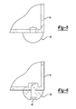
Figure 5 is a cross-sectional view of an assist handle mounted to a tank according to the principles of the present disclosure; -
Figure 6 is a cross-sectional view of an assist handle mounted to a tank according to an alternative embodiment of the present disclosure; -
Figure 7 is a cross-sectional view of an assist handle mounted to a tank according to yet another embodiment of the present disclosure; and -
Figure 8 is a perspective view of the vacuum illustrating an additional pivoting handle disposed on a center portion of the lid. - The following description is merely exemplary in nature and is not intended to limit the present disclosure, application, or uses. It should be understood that throughout the drawings, corresponding reference numerals indicate like or corresponding parts and features.
- Referring to
Figures 1-4 , a vacuum with at least one assist handle is shown, and is generally referred to asvacuum 10.Vacuum 10 includes ahousing 12 that encloses a suction device. The suction device is generally located withinhousing 12 at 14, and includes a mechanism that creates a suction force operable to collect dirt, debris, and other dry or wet waste matter, as known in the art. For example, suction device 14 may include an electric motor driving a suction impeller (not shown). -
Housing 12 may have atank portion 16 and alid portion 18.Tank 16 may be in fluid communication with suction device 14, and may be adapted to receive and storewaste matter 19 collected via suction device 14.Lid portion 18 may be removably mounted totank 16.Lid 18 may include at least oneupper handle 20 to facilitate removal oflid 18, and/or to facilitate mobility ofvacuum 10 during operation. In an alternative embodiment,lid 18 may be pivotable about hinges (not shown) disposed ontank 16 andlid 18, enabling access to the inside oftank 16. -
Vacuum 10 may includewheels 22 and/orcaster wheels 24 to further facilitate maneuverability ofvacuum 10.Wheels 22 and/orcaster wheels 24 may be mounted totank 16 via asuspension cross-member 26 in the form of a tube mounted totank 16. -
Tank 16 may include at least oneassist handle 28 to facilitate gripping andlifting tank 16.Assist handle 28 may be integrally formed withtank 16 and at least partially defined by abottom face 30 oftank 16 and at least one of aside face 32, 34 (shown inFigures 3 and 4 ) oftank 16, a rear face 36 (shown inFigure 1 ) oftank 16, a front face 38 (shown inFigure 2 ) oftank 16, or suspension cross-member 26 (shown inFigure 2 ). - In another embodiment,
assist handle 28 may be disposed ontank 16 substantially nearbottom face 30 on any ofside face rear face 36, andfront face 38.Assist handle 28 may be mounted totank 16 via an interference or snap fit, at least one threadedbolt 40 or other fastener, or other methods known in the art. Alternatively,assist handle 28 may be bonded to tank 16 viaadhesive 42. - In an exemplary embodiment,
vacuum 10 may include a plurality ofassist handles 28.Assist handles 28 may be disposed on any or all ofside face rear face 36,front face 38, andsuspension cross-member 26. -
Assist handles 28 may be ergonomically contoured to facilitate gripping and liftingvacuum 10 to dumpwaste matter 19 accumulated withintank 16 during operation ofvacuum 10. The ergonomic features ofassist handles 28 may include atapered portion 44,grooves 46, and/or other contours adapted to facilitate comfortable gripping.Wheels 22 and/orcaster wheels 24 provide sufficient clearance betweenassist handles 28 and the floor or ground to enable an operator to at least partially gripbottom face 30 oftank 16. - The
lid portion 18 may also include apivoting handle 50, as shown inFigure 8 .Pivoting handle 50 includes ahinge 52, about whichpivoting handle 50 is pivotable.Pivoting handle 50 may be pivoted substantially flush tolid 18 for convenience when not in use, and may be pivoted back to an upright position as desired. Thepivoting handle 50 may be utilized to push, pull or liftvacuum 10 to facilitate mobility.Pivoting handle 50 can also be utilized to lift thelid portion 18 off of thetank portion 16. Pivotinghandle 50 may be used alone or in combination withwheels upper handles 24 to transportvacuum 10. - The description of the present disclosure is merely exemplary in nature and, thus, variations that do not depart from the gist of the disclosure are intended to be within the scope of the disclosure. Such variations are not to be regarded as a departure from the spirit and scope of the disclosure.
Claims (13)
- A vacuum comprising:a housing including a tank portion; anda suction device disposed within said housing;wherein said tank portion is adapted to receive waste matter via said suction device, and said tank portion includes at least one assist handle adapted to facilitate gripping and lifting the vacuum to empty waste matter accumulated in said tank portion.
- The vacuum according to claim 1, wherein said at least one assist handle is at least partially defined by a bottom face of said tank portion.
- The vacuum according to claim 1, wherein said at least one assist handle is at least partially defined by one of a suspension cross-member, a rear face of said tank portion, or a side face of said tank portion.
- The vacuum according to claim 1, wherein said at least one assist handle is ergonomically contoured.
- The vacuum according to claim 1, wherein said at least one assist handle includes a tapered portion to facilitate gripping.
- The vacuum according to claim 1, wherein said at least one assist handle includes a plurality of grooves.
- The vacuum according to claim 1, further comprising a plurality of assist handles disposed on different sides of said tank portion.
- The vacuum according to claim 7, wherein said plurality of assist handles are at least partially defined by a bottom face of said tank portion.
- The vacuum according to claim 7, wherein said plurality of assist handles are at least partially defined by at least one of a suspension cross-member, a rear face of said tank portion, and a side face of said tank portion.
- The vacuum according to claim 7, wherein said plurality of assist handles are ergonomically contoured.
- The vacuum according to claim 1, wherein said at least one assist handle is integrally formed with said tank portion.
- The vacuum according to claim 1, wherein said at least one assist handle is mounted to said tank portion.
- The vacuum according to claim 1, further comprising a lid portion removably mounted to said tank portion to facilitate waste matter disposal.
Applications Claiming Priority (1)
| Application Number | Priority Date | Filing Date | Title |
|---|---|---|---|
| US11/870,974 US20090094787A1 (en) | 2007-10-11 | 2007-10-11 | Vacuum Having Assist Handles |
Publications (1)
| Publication Number | Publication Date |
|---|---|
| EP2047785A2 true EP2047785A2 (en) | 2009-04-15 |
Family
ID=40295577
Family Applications (1)
| Application Number | Title | Priority Date | Filing Date |
|---|---|---|---|
| EP08166111A Withdrawn EP2047785A2 (en) | 2007-10-11 | 2008-10-08 | Vacuum having assist handles |
Country Status (2)
| Country | Link |
|---|---|
| US (1) | US20090094787A1 (en) |
| EP (1) | EP2047785A2 (en) |
Cited By (1)
| Publication number | Priority date | Publication date | Assignee | Title |
|---|---|---|---|---|
| USD1049525S1 (en) * | 2022-08-30 | 2024-10-29 | Makita Corporation | Vacuum cleaner body |
Families Citing this family (1)
| Publication number | Priority date | Publication date | Assignee | Title |
|---|---|---|---|---|
| AU2011295774B2 (en) | 2010-09-01 | 2014-08-28 | Techtronic Floor Care Technology Limited | Recovery tank assembly for an extractor cleaning machine |
Family Cites Families (7)
| Publication number | Priority date | Publication date | Assignee | Title |
|---|---|---|---|---|
| US4827562A (en) * | 1987-03-20 | 1989-05-09 | Bissell Inc. | Liquid extraction surface cleaning apparatus |
| US5146647A (en) * | 1990-05-04 | 1992-09-15 | Bissell Inc. | Carpet extractor with bucket caddy |
| US5287587A (en) * | 1991-09-10 | 1994-02-22 | Yonkers Robert A | Self-contained, compact vacuum/extractor |
| USD443739S1 (en) * | 1998-08-31 | 2001-06-12 | Emerson Electric Co. | Combined wet and dry vacuum cleaner |
| US6378165B1 (en) * | 2000-02-17 | 2002-04-30 | Emerson Electric Co. | Pull handle with interlocking mounting mechanism for wet/dry vacuum appliance |
| US6510583B2 (en) * | 2001-03-30 | 2003-01-28 | Shop Vac Corporation | Cord retainer for vacuum cleaner |
| USD528255S1 (en) * | 2005-02-28 | 2006-09-12 | Shop Vac Corporation | Vacuum cleaner |
-
2007
- 2007-10-11 US US11/870,974 patent/US20090094787A1/en not_active Abandoned
-
2008
- 2008-10-08 EP EP08166111A patent/EP2047785A2/en not_active Withdrawn
Cited By (1)
| Publication number | Priority date | Publication date | Assignee | Title |
|---|---|---|---|---|
| USD1049525S1 (en) * | 2022-08-30 | 2024-10-29 | Makita Corporation | Vacuum cleaner body |
Also Published As
| Publication number | Publication date |
|---|---|
| US20090094787A1 (en) | 2009-04-16 |
Similar Documents
| Publication | Publication Date | Title |
|---|---|---|
| EP1887918B1 (en) | Floor sweeping and scrubbing machine | |
| US4709440A (en) | Mobile clean-up device | |
| US8429789B2 (en) | Vacuum having accessory storage features | |
| US11465662B2 (en) | Powered sled | |
| US8684374B2 (en) | Cart accessory handle for lifting and dumping | |
| CN103253290A (en) | Combination device of trolley and bucket structure for carrying cleaning materials | |
| US20110000382A1 (en) | Trash receptacle for collecting and compacting waste and related method of use | |
| US20090189498A1 (en) | Cleaning cart | |
| US8944742B2 (en) | Means for moving trash receptacles | |
| AU2003248316B2 (en) | Fixing Device for Attaching/detaching Dust Receptacle of Cyclone-type Vacuum Cleaner and Vacuum Cleaner Having the Same | |
| CA2645166A1 (en) | Wheeled waste collection container | |
| US20160242618A1 (en) | Center-handled large debris dust pan | |
| US7805802B2 (en) | Floor cleaning machine debris collection system | |
| US20090094787A1 (en) | Vacuum Having Assist Handles | |
| JP2004231148A (en) | Litter cleaner attachable to moving vehicle | |
| JP2001037695A (en) | Hand roller brush cleaner | |
| US8636289B2 (en) | Straw trapper for wheelbarrow | |
| WO2007115370A1 (en) | Trolley | |
| JP2003102663A (en) | Floor cleaning cleaner | |
| WO2021235929A1 (en) | Scrubber-dryer system | |
| EP1524040A2 (en) | Washing tank in particular for the brakes of industrial and similar vehicles | |
| CN101600837B (en) | Suction cleaning machine with a travel drive | |
| CN101896109B (en) | Floor-cleaning appliance | |
| CN115997060A (en) | Self-propelled sweeper and method for manufacturing the sweeper | |
| CN102316780B (en) | Suction cleaning device |
Legal Events
| Date | Code | Title | Description |
|---|---|---|---|
| PUAI | Public reference made under article 153(3) epc to a published international application that has entered the european phase |
Free format text: ORIGINAL CODE: 0009012 |
|
| AK | Designated contracting states |
Kind code of ref document: A2 Designated state(s): AT BE BG CH CY CZ DE DK EE ES FI FR GB GR HR HU IE IS IT LI LT LU LV MC MT NL NO PL PT RO SE SI SK TR |
|
| AX | Request for extension of the european patent |
Extension state: AL BA MK RS |
|
| STAA | Information on the status of an ep patent application or granted ep patent |
Free format text: STATUS: THE APPLICATION IS DEEMED TO BE WITHDRAWN |
|
| 18D | Application deemed to be withdrawn |
Effective date: 20110503 |