EP2045850A1 - Process for producing battery can and process for producing hermetically sealed battery - Google Patents
Process for producing battery can and process for producing hermetically sealed battery Download PDFInfo
- Publication number
- EP2045850A1 EP2045850A1 EP07849969A EP07849969A EP2045850A1 EP 2045850 A1 EP2045850 A1 EP 2045850A1 EP 07849969 A EP07849969 A EP 07849969A EP 07849969 A EP07849969 A EP 07849969A EP 2045850 A1 EP2045850 A1 EP 2045850A1
- Authority
- EP
- European Patent Office
- Prior art keywords
- cylindrical body
- battery case
- blade
- battery
- opening
- Prior art date
- Legal status (The legal status is an assumption and is not a legal conclusion. Google has not performed a legal analysis and makes no representation as to the accuracy of the status listed.)
- Granted
Links
Images




Classifications
-
- B—PERFORMING OPERATIONS; TRANSPORTING
- B21—MECHANICAL METAL-WORKING WITHOUT ESSENTIALLY REMOVING MATERIAL; PUNCHING METAL
- B21D—WORKING OR PROCESSING OF SHEET METAL OR METAL TUBES, RODS OR PROFILES WITHOUT ESSENTIALLY REMOVING MATERIAL; PUNCHING METAL
- B21D51/00—Making hollow objects
- B21D51/16—Making hollow objects characterised by the use of the objects
- B21D51/18—Making hollow objects characterised by the use of the objects vessels, e.g. tubs, vats, tanks, sinks, or the like
-
- B—PERFORMING OPERATIONS; TRANSPORTING
- B23—MACHINE TOOLS; METAL-WORKING NOT OTHERWISE PROVIDED FOR
- B23D—PLANING; SLOTTING; SHEARING; BROACHING; SAWING; FILING; SCRAPING; LIKE OPERATIONS FOR WORKING METAL BY REMOVING MATERIAL, NOT OTHERWISE PROVIDED FOR
- B23D21/00—Machines or devices for shearing or cutting tubes
-
- H—ELECTRICITY
- H01—ELECTRIC ELEMENTS
- H01M—PROCESSES OR MEANS, e.g. BATTERIES, FOR THE DIRECT CONVERSION OF CHEMICAL ENERGY INTO ELECTRICAL ENERGY
- H01M50/00—Constructional details or processes of manufacture of the non-active parts of electrochemical cells other than fuel cells, e.g. hybrid cells
- H01M50/10—Primary casings; Jackets or wrappings
- H01M50/116—Primary casings; Jackets or wrappings characterised by the material
- H01M50/117—Inorganic material
- H01M50/119—Metals
-
- H—ELECTRICITY
- H01—ELECTRIC ELEMENTS
- H01M—PROCESSES OR MEANS, e.g. BATTERIES, FOR THE DIRECT CONVERSION OF CHEMICAL ENERGY INTO ELECTRICAL ENERGY
- H01M50/00—Constructional details or processes of manufacture of the non-active parts of electrochemical cells other than fuel cells, e.g. hybrid cells
- H01M50/50—Current conducting connections for cells or batteries
- H01M50/543—Terminals
- H01M50/545—Terminals formed by the casing of the cells
-
- B—PERFORMING OPERATIONS; TRANSPORTING
- B23—MACHINE TOOLS; METAL-WORKING NOT OTHERWISE PROVIDED FOR
- B23D—PLANING; SLOTTING; SHEARING; BROACHING; SAWING; FILING; SCRAPING; LIKE OPERATIONS FOR WORKING METAL BY REMOVING MATERIAL, NOT OTHERWISE PROVIDED FOR
- B23D21/00—Machines or devices for shearing or cutting tubes
- B23D21/006—Machines or devices for shearing or cutting tubes and sealing, crushing or chamfering the tubes
-
- H—ELECTRICITY
- H01—ELECTRIC ELEMENTS
- H01M—PROCESSES OR MEANS, e.g. BATTERIES, FOR THE DIRECT CONVERSION OF CHEMICAL ENERGY INTO ELECTRICAL ENERGY
- H01M50/00—Constructional details or processes of manufacture of the non-active parts of electrochemical cells other than fuel cells, e.g. hybrid cells
- H01M50/10—Primary casings; Jackets or wrappings
- H01M50/102—Primary casings; Jackets or wrappings characterised by their shape or physical structure
- H01M50/107—Primary casings; Jackets or wrappings characterised by their shape or physical structure having curved cross-section, e.g. round or elliptic
-
- Y—GENERAL TAGGING OF NEW TECHNOLOGICAL DEVELOPMENTS; GENERAL TAGGING OF CROSS-SECTIONAL TECHNOLOGIES SPANNING OVER SEVERAL SECTIONS OF THE IPC; TECHNICAL SUBJECTS COVERED BY FORMER USPC CROSS-REFERENCE ART COLLECTIONS [XRACs] AND DIGESTS
- Y02—TECHNOLOGIES OR APPLICATIONS FOR MITIGATION OR ADAPTATION AGAINST CLIMATE CHANGE
- Y02E—REDUCTION OF GREENHOUSE GAS [GHG] EMISSIONS, RELATED TO ENERGY GENERATION, TRANSMISSION OR DISTRIBUTION
- Y02E60/00—Enabling technologies; Technologies with a potential or indirect contribution to GHG emissions mitigation
- Y02E60/10—Energy storage using batteries
-
- Y—GENERAL TAGGING OF NEW TECHNOLOGICAL DEVELOPMENTS; GENERAL TAGGING OF CROSS-SECTIONAL TECHNOLOGIES SPANNING OVER SEVERAL SECTIONS OF THE IPC; TECHNICAL SUBJECTS COVERED BY FORMER USPC CROSS-REFERENCE ART COLLECTIONS [XRACs] AND DIGESTS
- Y10—TECHNICAL SUBJECTS COVERED BY FORMER USPC
- Y10T—TECHNICAL SUBJECTS COVERED BY FORMER US CLASSIFICATION
- Y10T29/00—Metal working
- Y10T29/49—Method of mechanical manufacture
- Y10T29/49002—Electrical device making
- Y10T29/49108—Electric battery cell making
Definitions
- the present invention relates to a method for manufacturing battery cases for hermetic batteries such as primary and secondary batteries and a method for manufacturing hermetic batteries using the battery cases obtained by the former method.
- Hermetic batteries such as primary and secondary batteries are assembled by arranging battery elements such as a positive electrode, a negative electrode and an electrolyte in a cylindrical battery case having a closed end and sealing an opening of the battery case with a lid and a gasket.
- the battery case is formed by drawing a metallic plate thin to form a cylindrical body having a closed end and cutting part of the cylindrical body at an opening thereof along its circumference.
- the cutting is carried out by pressing using a punch and a die.
- the pressing inevitably leaves burrs on the cut surface of the cylindrical body because a certain clearance lies between the punch and the die. The occurrence of the burrs may be reduced by optimizing the clearance, but the burrs cannot be completely eliminated.
- an active material mixture layer on the surface of a wound positive or negative electrode may partially be peeled off when it comes into contact with the burrs. If a peeled piece of the layer enters the battery case, it may cause internal short circuit. The burrs generated on the end face of the battery case may also come off to cause external short circuit between the battery case and the lid (sealing plate), thereby causing voltage drop. Further, if the gasket comes into contact with the burrs when it is fitted in the opening of the battery case, the gasket may partially be scratched, which may possibly decrease the hermeticity of the battery.
- Patent Literature 1 discloses a method for forming a closed-end cylindrical battery case provided with a reverse-tapered opening having a larger diameter than the diameter of a middle part thereof. Since the opening is reverse-tapered, burrs formed on the end face are prevented from coming into contact with the gasket for sealing the battery case. Further, when the battery elements are placed in the battery case, contact between the active material mixture layer and the burrs is also avoided. Accordingly, the entry of the foreign matter in the battery case is prevented.
- Patent Literatures 2 and 3 disclose a method for curving the end face of the reverse-tapered opening of the battery case. This method makes it possible to prevent the opening from scratching the gasket and the foreign matter such as a peeled piece of the active material mixture layer from entering the battery case.
- a closed-end cylindrical body 100 is formed to have an opening having a reverse-tapered part 101 having a larger inner diameter d2 than the inner diameter d1 of the middle part of the cylindrical body 100 and another reverse-tapered part 102 having a larger inner diameter d3 than d2. Then, the reverse-tapered part 102 is cut off in the direction parallel to the side face of the cylindrical body 100 (in the direction of an arrow A depicted in FIG. 7B ) to leave a rounded inner face at the opening of the battery case as shown in FIG. 7A .
- FIG. 8 shows a flowchart of a general battery assembly steps.
- a metallic plate is drawn thin (S1) to form a closed-end cylindrical body 100.
- part of the cylindrical body 100 at the opening thereof is cut away (S2) to obtain a battery case 200.
- battery elements are placed in the battery case 200 (S3) and the battery case 200 is subjected to beading to form a bead near the opening (S4).
- a sealing member (a lid and a gasket) is fitted in the opening of the battery case 200 (S5) and the battery case 200 is sealed by crimping (S6). In this manner, the battery is assembled.
- the conventional measures have focused on the step in which the burrs formed on the end face of the battery case 200 may come into contact with the positive or negative electrode active material mixture layer (S3) or the gasket (S5).
- the inventor of the present invention has noted the step of pressing a certain part of the battery case 200 with a pressing member while the battery case 200 is fixed by a holding jig, i.e., the steps of beading (S4) and crimping (S6).
- FIG. 9 shows a common way of the beading (S4).
- a pressing member (die) 301 is used to press the outer circumference of the battery case 200 toward an axis of the battery case 200 (in the direction of an arrow
- FIGS. 10A and 10B show a common way of the crimping (S6).
- a gasket and a lid fitted in the opening of the battery case 200 are not depicted.
- the battery case 200 is fixed by a holding jig 400 at the bead.
- a pressing member (crimping jig) 401 is pressed against the opening end of the battery case 200 in the direction of an arrow A such that the opening of the battery case 200 is crimp-sealed as shown in FIG. 10B .
- the opening end of the battery case 200 is pressed by the retaining jig 302 in the beading step (S4) and by the crimping jig 301 in the crimping step (S6).
- the burrs formed on the end face of the battery case 200 are shaved off by these jigs and the shavings of the burrs may possibly come into the battery case 200.
- a main object of the invention is to provide a method for manufacturing a battery case in which burrs formed on the end face of the battery case are prevented from entering the battery case in the assembly process of the battery (in the beading or crimping step).
- FIG. 11A illustrates the step of cutting part of the cylindrical body 100 at an opening 11 thereof and FIG. 11B shows a burr 130a formed on the cut surface 120a of the cylindrical body 100 after the cutting.
- the cutting step shown in FIG. 11A corresponds to the process shown in FIG. 7B .
- a punch 500 arranged outside the cylindrical body 100 e.g., a cylindrical punch having an inner diameter larger than the outer diameter of the cylindrical body 100
- a die 501 arranged inside the cylindrical body 100 e.g., a cylindrical die having an outer diameter smaller than the inner diameter of the cylindrical body 100
- a burr 130a extending upward in the direction parallel to the side face of the cylindrical body 100 is formed on the cut surface 120a of the cylindrical body 100 as shown in FIG. 11B (hereinafter, it is referred to as an upward burr).
- the upward burr 130a is generated on the end face of the cylindrical body (battery case) 100, it may possibly be hit and crushed by the jig 22 or 32 in the beading or crimping step shown in FIGS. 9 , 10A and 10B .
- part of the cylindrical body 100 at the opening 11 is cut away in the direction parallel to the side face of the cylindrical body 100.
- the cutting may be carried out in the direction perpendicular to the side face of the cylindrical body 100.
- a punch 503 arranged inside the cylindrical body 100 e.g., a cylindrical punch having an outer diameter smaller than the inner diameter of the cylindrical body 100
- a die 502 arranged outside the cylindrical body 100 e.g., a cylindrical die having an inner diameter larger than the outer diameter of the cylindrical body 100
- a burr 130b extending outward in the direction perpendicular to the side face of the cylindrical body 100 is formed on the cut surface 120b of the cylindrical body 100 as shown in FIG. 12B (hereinafter, it is referred to as an outward burr).
- outward burr 130b is generated on the end face of the cylindrical body (battery case) 100, it may possibly be hit and crushed by the jig 22 or 32 in the beading or crimping step just like the upward burr 130a.
- the inventor of the present invention has found that the possibility that the burr on the end face of the cylindrical body comes off due to contact with the jig used in the battery assembling step (beading or crimping step) and enters the battery case is dependent on the extending direction of the burr.
- the inventor has arrived at a finding that the possibility of the contact between the burr and the jig in the beading or crimping step is minimized by cutting the cylindrical body 100 in the direction opposite the direction shown in FIG.
- an inward burr a burr extending inward in the direction perpendicular to the side face of the cylindrical body 100
- a method for manufacturing a battery case of the present invention includes the steps of: drawing a metallic plate to form a cylindrical body having a closed end; and cutting away part of the cylindrical body at an opening thereof in a direction perpendicular to an axis of the cylindrical body, wherein the step of cutting the cylindrical body is carried out by arranging a first blade inside the cylindrical body and a second blade outside the cylindrical body closer to the opening of the cylindrical body than the first blade and moving the second blade relatively toward the axis of the cylindrical body with the first blade kept abutting the inner circumference of the cylindrical body.
- an inward burr formed on the cut surface of the cylindrical body or an end face of the battery case is effectively prevented from entering the battery case in the assembly of the battery.
- the first blade preferably consists of a round blade having an outer diameter smaller than the inner diameter of the cylindrical body.
- the second blade preferably makes contact with the cylindrical body at a substantially arc-shaped part thereof having an inner diameter larger than the outer diameter of the cylindrical body.
- the cylindrical body is preferably rotated about its axis and moved along the substantially arc-shaped part of the second blade.
- the burr formed on the end face of the battery case is prevented from entering the battery case in the battery assembly step, thereby effectively reducing the possibility of the internal short circuit between the positive and negative electrodes. Therefore, highly reliable batteries are manufactured with stability. Further, the present invention also makes it possible to effectively prevent the possibility of external short circuit between the battery case and the lid due to the burr formed on and come off the end face of the battery case. As a result, the batteries are manufactured with stable performance.
- FIGS. 1A to 1C schematically show the method for manufacturing a battery case according to an embodiment of the present invention.
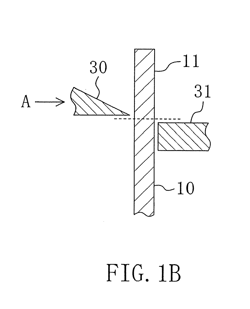
- FIG. 1A is a sectional view of a closed-end cylindrical body 10 obtained by drawing a metallic plate. Part of the cylindrical body 10 at an opening 11 thereof is cut away in the direction perpendicular to the axis of the cylindrical body 10 (along a dotted line shown in the figure) to prepare a battery case.
- a second blade 30 arranged on the outer circumference of the cylindrical body 10 is moved relatively toward an axis of the cylindrical body 10 (in the direction of an arrow A shown in FIG. 1B ) with a first blade 31 kept abutting the inner circumference of the cylindrical body 10 to cut the cylindrical body 10.
- an inward burr 13 extending inward in the direction perpendicular to the side face of the cylindrical body 10 is formed on a cut surface 12 of the cylindrical body 10 as shown in FIG. 1C .
- the burr formed on the cut surface (end face of the battery case) of the cylindrical body 10 extends inward in the direction perpendicular to the side face of the cylindrical body 10, contact between the burr and a jig used in the beading or crimping step is prevented as much as possible. Therefore, the burr formed on the end face of the battery case is effectively prevented from coming in the battery case in the assembly process of the battery.
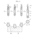
- FIG. 2 is a view specifically illustrating the step of cutting the cylindrical body 10 according to the present embodiment.
- a cylindrical punch (first blade) 31 having an outer diameter smaller than the inner diameter of the cylindrical body 10 is arranged inside the cylindrical body 10 and a die (second blade) 30 is arranged outside the cylindrical body 10.
- the die 30 makes contact with the cylindrical body 10 at a substantially arc-shaped part thereof having an inner diameter larger than the outer diameter of the cylindrical body 10.
- the punch 31 kept abutting the inner circumference of the cylindrical body 10
- the cylindrical body 10 is rotated about its axis in the direction of an arrow A and the die 30 is simultaneously moved in the direction of an arrow B to cut the cylindrical body 10.
- the cutting of the cylindrical body 10 in the predetermined direction is carried out by merely moving the die 30 toward the axis of the cylindrical body 10 and the need of arranging the die 30 around the entire circumference of the cylindrical body 10 is eliminated.
- the die 30 in the form shown in FIG. 2 may be replaced with a round blade.
- FIG. 3 schematically illustrates another step of cutting the cylindrical body 10 according to the present embodiment.
- a cylindrical punch (first blade) 41 having an outer diameter smaller than the inner diameter of the cylindrical body 10 is arranged inside the cylindrical body 10 and a die (second blade) 40 is arranged outside the cylindrical body 10.
- the die 40 makes contact with the cylindrical body 10 at a substantially arc-shaped part thereof having an inner diameter larger than the outer diameter of the cylindrical body 10.
- the cylindrical body 10 is rotated about its axis and simultaneously moved along the substantially arc-shaped part 40a of the die 40 to cut the cylindrical body 10.
- a plurality of cylindrical bodies 10 can be cut by successively moving the cylindrical bodies 10 along the substantially arc-shaped part 40a of the die 40. This makes it possible to achieve efficient mass production of the battery case.
- the step of cutting the cylindrical body 10 of the present invention is not limited to the foregoing steps.
- the cutting may be carried out in any way as long as the burr 13 extending inward in the direction perpendicular to the side face of the cylindrical body 10 is formed on the cut surface 12 of the cylindrical body 10.
- the cylindrical body 10 may be moved toward the second blade 30 to cut the cylindrical body 10.
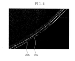
- FIG. 4 is an image showing part of the end face of the battery case manufactured by the method of the present invention.
- the cutting of the cylindrical body 10 is carried out by moving the second blade 30 arranged outside the cylindrical body 10 toward the inside of the cylindrical body 10.
- the obtained end face of the battery case includes a cut surface 20a on the outer circumferential side and a fractured surface 20b on the inner circumferential side. Further, an edge of the opening of the battery case on the outer circumferential side is rounded.
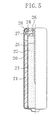
- FIG. 5 is a sectional view illustrating the structure of a cylindrical hermetic battery including a battery case obtained by the method for manufacturing the battery case of the present invention.
- the hermetic battery according to the present invention is manufactured by the general process shown in FIG. 8 .
- positive and negative battery elements are arranged in the battery case with a separator interposed therebetween.
- a bead is formed around the circumference of part of the battery case near the opening thereof, a lid and a gasket are placed in the opening of the battery case, and then the opening of the battery case is crimp-sealed. In this manner, the hermetic battery is obtained.
- the hermetic battery shown in FIG. 5 is an example of an alkaline dry battery.
- the battery case also serving as a positive electrode terminal
- positive electrode mixture pellets 21 and a gelled negative electrode 22 are arranged with a separator 23 interposed therebetween.
- a bead 27 is formed around the circumference of part of the battery case 20 near the opening of the battery case 20.
- a lid 26 also serving as a negative electrode terminal
- An end 28 of the battery case 20 is crimped to the lid 26 with the gasket 24 interposed therebetween to seal the opening of the battery case 20.
- FIG. 6 shows a graph of lot-to-lot comparison of the rate of occurrence of voltage drop among mass-produced nickel-metal hydride batteries. The voltage drop is caused by short circuit between the battery case 20 and the lid 26 due to the burr coming off the end face of the battery case 20.
- Batteries of lot Nos. 1 to 7 include battery cases manufactured by the method of the present invention (inward burr formed on the end face).
- batteries of lot No. 8 include battery cases manufactured by the method explained in FIG. 12A (outward burr formed on the end face).
- FIG. 6 the rate of occurrence of voltage drop among the batteries according to the method of the present invention is reduced by one digit as compared with that among the batteries to which the method of the present invention is not applied.
- the method of the present invention exhibits superior effect if it is applied to the mass production of the batteries and improves the reliability of the mass-produced batteries.
- the application of the present invention allows improvement in yield of the mass production.
- the preferred embodiments of the present invention described above are not limitative and may be varied in many ways.
- the hermetic batteries of interest are not particularly limited and the invention is applicable to primary batteries such as manganese dry batteries and lithium batteries and secondary batteries such as lithium ion batteries and nickel-metal hydride batteries.
- the present invention is useful for hermetic batteries required to be highly reliable and applicable to primary and secondary batteries.
Landscapes
- Chemical & Material Sciences (AREA)
- Engineering & Computer Science (AREA)
- Mechanical Engineering (AREA)
- Chemical Kinetics & Catalysis (AREA)
- Electrochemistry (AREA)
- General Chemical & Material Sciences (AREA)
- Inorganic Chemistry (AREA)
- Sealing Battery Cases Or Jackets (AREA)
- Primary Cells (AREA)
- Punching Or Piercing (AREA)
- Secondary Cells (AREA)
Abstract

Description
- The present invention relates to a method for manufacturing battery cases for hermetic batteries such as primary and secondary batteries and a method for manufacturing hermetic batteries using the battery cases obtained by the former method.
- Hermetic batteries such as primary and secondary batteries are assembled by arranging battery elements such as a positive electrode, a negative electrode and an electrolyte in a cylindrical battery case having a closed end and sealing an opening of the battery case with a lid and a gasket.
- If foreign matter such as a piece of metal comes into the battery case in the assembly process and internal short circuit occurs, output voltage of the battery may be decreased or unfavorable gas may be generated. Therefore, the entry of the foreign matter in the assembly process should be prevented for improved battery reliability.
- The battery case is formed by drawing a metallic plate thin to form a cylindrical body having a closed end and cutting part of the cylindrical body at an opening thereof along its circumference. In general, the cutting is carried out by pressing using a punch and a die. However, the pressing inevitably leaves burrs on the cut surface of the cylindrical body because a certain clearance lies between the punch and the die. The occurrence of the burrs may be reduced by optimizing the clearance, but the burrs cannot be completely eliminated.
- If there are burrs on the cut surface of the cylindrical body or an end face of the battery case, problems may arise when the battery elements are placed in the battery case. More specifically, an active material mixture layer on the surface of a wound positive or negative electrode may partially be peeled off when it comes into contact with the burrs. If a peeled piece of the layer enters the battery case, it may cause internal short circuit. The burrs generated on the end face of the battery case may also come off to cause external short circuit between the battery case and the lid (sealing plate), thereby causing voltage drop. Further, if the gasket comes into contact with the burrs when it is fitted in the opening of the battery case, the gasket may partially be scratched, which may possibly decrease the hermeticity of the battery.
- In order to solve these problems, it is necessary to prevent the generation of the burrs as much as possible in the step of cutting the closed-end cylindrical body. However, since the burrs are inevitably generated, it is more practical to take measures to prevent the entry of the foreign matter in the battery case.
- As an example of such measures,
Patent Literature 1 discloses a method for forming a closed-end cylindrical battery case provided with a reverse-tapered opening having a larger diameter than the diameter of a middle part thereof. Since the opening is reverse-tapered, burrs formed on the end face are prevented from coming into contact with the gasket for sealing the battery case. Further, when the battery elements are placed in the battery case, contact between the active material mixture layer and the burrs is also avoided. Accordingly, the entry of the foreign matter in the battery case is prevented. - As another example,
Patent Literatures - The end face of the opening is curved in the following manner. As shown in
FIG. 7B , a closed-endcylindrical body 100 is formed to have an opening having a reverse-tapered part 101 having a larger inner diameter d2 than the inner diameter d1 of the middle part of thecylindrical body 100 and another reverse-tapered part 102 having a larger inner diameter d3 than d2. Then, the reverse-tapered part 102 is cut off in the direction parallel to the side face of the cylindrical body 100 (in the direction of an arrow A depicted inFIG. 7B ) to leave a rounded inner face at the opening of the battery case as shown inFIG. 7A . - Patent Literature 1: Japanese Unexamined Patent Publication No.
2001-52656 - Patent Literature 2: Japanese Unexamined Patent Publication No.
9-161736 - Patent Literature 3: Japanese Unexamined Patent Publication No.
10-321198 - The above-mentioned conventional measures are useful in view of reducing the effect of the burrs formed on the end face of the battery case. However, there still remains a possibility that the foreign matter enters the battery case and brings about internal short circuit due to variations in the production process. In particular, as the need for batteries of smaller size and higher capacity has been increasing in recent years, not only positive and negative electrodes but also a separator between them is becoming thinner. Therefore, a very small foreign matter that has not been regarded as a problem so far could be a cause of decrease of battery characteristics if it enters the battery case. Further, when the burrs formed on the end face of the battery case come off to cause external short circuit between the battery case and the lid, voltage drop may possibly occur.
- The conventional measures described above have focused on the contact between the burrs formed on the end face of the battery case and the positive or negative electrode active material mixture layer or the gasket.
- After a close study of the effect of the burrs formed on the end face of the battery case, the inventor of the present invention has reached the following finding distinct from the conventional point of view.
-
FIG. 8 shows a flowchart of a general battery assembly steps. First, a metallic plate is drawn thin (S1) to form a closed-endcylindrical body 100. Then, part of thecylindrical body 100 at the opening thereof is cut away (S2) to obtain abattery case 200. Then, battery elements are placed in the battery case 200 (S3) and thebattery case 200 is subjected to beading to form a bead near the opening (S4). Subsequently, a sealing member (a lid and a gasket) is fitted in the opening of the battery case 200 (S5) and thebattery case 200 is sealed by crimping (S6). In this manner, the battery is assembled. - The conventional measures have focused on the step in which the burrs formed on the end face of the
battery case 200 may come into contact with the positive or negative electrode active material mixture layer (S3) or the gasket (S5). - The inventor of the present invention has noted the step of pressing a certain part of the
battery case 200 with a pressing member while thebattery case 200 is fixed by a holding jig, i.e., the steps of beading (S4) and crimping (S6). -
FIG. 9 shows a common way of the beading (S4). First, in the state where aholding jig 300 holds thebattery case 200 and aretaining jig 302 abuts the opening end of thebattery case 200, a pressing member (die) 301 is used to press the outer circumference of thebattery case 200 toward an axis of the battery case 200 (in the direction of an arrow - A). Simultaneously, the bottom of the
battery case 200 is pressed in the axial direction of the battery case 200 (in the direction of an arrow B) together with theholding jig 300 to form abead 201 around the circumference of thebattery case 200. -
FIGS. 10A and 10B show a common way of the crimping (S6). In these figures, a gasket and a lid fitted in the opening of thebattery case 200 are not depicted. As shown inFIG. 10A , thebattery case 200 is fixed by aholding jig 400 at the bead. In this state, a pressing member (crimping jig) 401 is pressed against the opening end of thebattery case 200 in the direction of an arrow A such that the opening of thebattery case 200 is crimp-sealed as shown inFIG. 10B . - As shown in
FIGS. 9 ,10A and 10B , the opening end of thebattery case 200 is pressed by theretaining jig 302 in the beading step (S4) and by thecrimping jig 301 in the crimping step (S6). As a result, the burrs formed on the end face of thebattery case 200 are shaved off by these jigs and the shavings of the burrs may possibly come into thebattery case 200. Even if the shavings of the burrs may not directly enter thebattery case 200, the shavings adhered to thejigs battery case 200 in the steps of beading (S4) and crimping (S6) if the steps (S4) and (S6) are repeated using thejigs battery case 200 of the foreign matter derived from the burrs on the end face of thebattery case 200. - In view of the foregoing, the present invention has been achieved. A main object of the invention is to provide a method for manufacturing a battery case in which burrs formed on the end face of the battery case are prevented from entering the battery case in the assembly process of the battery (in the beading or crimping step).
- In order to achieve the object, the inventor of the present invention has made a study on the states of the burrs formed.
FIG. 11A illustrates the step of cutting part of thecylindrical body 100 at anopening 11 thereof andFIG. 11B shows aburr 130a formed on thecut surface 120a of thecylindrical body 100 after the cutting. - The cutting step shown in
FIG. 11A corresponds to the process shown inFIG. 7B . Specifically, apunch 500 arranged outside the cylindrical body 100 (e.g., a cylindrical punch having an inner diameter larger than the outer diameter of the cylindrical body 100) is pressed toward adie 501 arranged inside the cylindrical body 100 (e.g., a cylindrical die having an outer diameter smaller than the inner diameter of the cylindrical body 100) to cut thecylindrical body 100. According to this method, aburr 130a extending upward in the direction parallel to the side face of thecylindrical body 100 is formed on thecut surface 120a of thecylindrical body 100 as shown inFIG. 11B (hereinafter, it is referred to as an upward burr). - If the
upward burr 130a is generated on the end face of the cylindrical body (battery case) 100, it may possibly be hit and crushed by thejig 22 or 32 in the beading or crimping step shown inFIGS. 9 ,10A and 10B . - In the cutting step shown in
FIG. 11A , part of thecylindrical body 100 at theopening 11 is cut away in the direction parallel to the side face of thecylindrical body 100. However, the cutting may be carried out in the direction perpendicular to the side face of thecylindrical body 100. In this case, apunch 503 arranged inside the cylindrical body 100 (e.g., a cylindrical punch having an outer diameter smaller than the inner diameter of the cylindrical body 100) is pressed toward adie 502 arranged outside the cylindrical body 100 (e.g., a cylindrical die having an inner diameter larger than the outer diameter of the cylindrical body 100) to cut thecylindrical body 100. According to this method, aburr 130b extending outward in the direction perpendicular to the side face of thecylindrical body 100 is formed on thecut surface 120b of thecylindrical body 100 as shown inFIG. 12B (hereinafter, it is referred to as an outward burr). - If the
outward burr 130b is generated on the end face of the cylindrical body (battery case) 100, it may possibly be hit and crushed by thejig 22 or 32 in the beading or crimping step just like theupward burr 130a. - With the foregoing in mind, the inventor of the present invention has found that the possibility that the burr on the end face of the cylindrical body comes off due to contact with the jig used in the battery assembling step (beading or crimping step) and enters the battery case is dependent on the extending direction of the burr. As a result, the inventor has arrived at a finding that the possibility of the contact between the burr and the jig in the beading or crimping step is minimized by cutting the
cylindrical body 100 in the direction opposite the direction shown inFIG. 12A , i.e., by pressing the punch arranged outside thecylindrical body 100 toward the die arranged inside thecylindrical body 100, to form a burr extending inward in the direction perpendicular to the side face of the cylindrical body 100 (hereinafter it is referred to as an inward burr). - Accordingly, a method for manufacturing a battery case of the present invention includes the steps of: drawing a metallic plate to form a cylindrical body having a closed end; and cutting away part of the cylindrical body at an opening thereof in a direction perpendicular to an axis of the cylindrical body, wherein the step of cutting the cylindrical body is carried out by arranging a first blade inside the cylindrical body and a second blade outside the cylindrical body closer to the opening of the cylindrical body than the first blade and moving the second blade relatively toward the axis of the cylindrical body with the first blade kept abutting the inner circumference of the cylindrical body.
- According to this method, an inward burr formed on the cut surface of the cylindrical body or an end face of the battery case is effectively prevented from entering the battery case in the assembly of the battery.
- The first blade preferably consists of a round blade having an outer diameter smaller than the inner diameter of the cylindrical body. The second blade preferably makes contact with the cylindrical body at a substantially arc-shaped part thereof having an inner diameter larger than the outer diameter of the cylindrical body.
- In the step of cutting the cylindrical body, the cylindrical body is preferably rotated about its axis and moved along the substantially arc-shaped part of the second blade.
- According to the method for manufacturing the battery case of the present invention, the burr formed on the end face of the battery case is prevented from entering the battery case in the battery assembly step, thereby effectively reducing the possibility of the internal short circuit between the positive and negative electrodes. Therefore, highly reliable batteries are manufactured with stability. Further, the present invention also makes it possible to effectively prevent the possibility of external short circuit between the battery case and the lid due to the burr formed on and come off the end face of the battery case. As a result, the batteries are manufactured with stable performance.
-
- [
FIG. 1 ]
FIGS. 1A, 1B and 1C are views illustrating a method for manufacturing a battery case according to an embodiment of the present invention, whileFIG. 1A is a sectional view of a cylindrical body,FIG. 1B is a partial enlargement illustrating the step of cutting the cylindrical body andFIG. 1C is a view illustrating a cut surface of the cylindrical body. - [
FIG. 2 ]
FIG. 2 is a view specifically illustrating the step of cutting the cylindrical body according to the embodiment. - [
FIG. 3 ]
FIG. 3 is a view specifically illustrating another step of cutting the cylindrical body according to the embodiment. - [
FIG. 4 ]
FIG. 4 is an image showing part of an end face of the battery case according to the embodiment. - [
FIG. 5 ]
FIG. 5 is a sectional view illustrating the structure of a cylindrical hermetic battery according to the present invention. - [
FIG. 6 ]
FIG. 6 is a graph illustrating the rate of occurrence of voltage drop among batteries according to the present invention. - [
FIG. 7 ]
FIGS. 7A and 7B are views illustrating a conventional step of cutting the cylindrical body. - [
FIG. 8 ]
FIG. 8 is a flowchart illustrating conventional battery assembly steps. - [
FIG. 9 ]
FIG. 9 is a sectional view illustrating a conventional beading step. - [
FIG. 10 ]
FIGS. 10A and 10B are sectional views illustrating a conventional crimping step. - [
FIG. 11 ]
FIGS. 11A and 11B are sectional views illustrating how burrs are formed in the conventional step of cutting the cylindrical body. - [
FIG. 12 ]
FIGS. 12A and 12B are sectional views illustrating how burrs are formed in the conventional step of cutting the cylindrical body. -
- 10
- Cylindrical body
- 12
- Cut surface
- 13
- Burr
- 20
- Battery case
- 20a
- Cut surface
- 20b
- Fractured surface
- 21
- Positive electrode mixture pellet
- 22
- Gelled negative electrode
- 22, 32
- Jig
- 23
- Separator
- 24
- Gasket
- 25
- Negative electrode collector
- 26
- Lid
- 27
- Bead
- 30,40
- Die (second blade)
- 31, 41
- Punch (first blade)
- Hereinafter, an embodiment of the present invention will be described with reference to the drawings. In the following drawings, components having substantially the same function are identified by the same reference numeral to omit lengthy explanation. It should be noted that the present invention is not limited to the embodiment.
-
FIGS. 1A to 1C schematically show the method for manufacturing a battery case according to an embodiment of the present invention.FIG. 1A is a sectional view of a closed-endcylindrical body 10 obtained by drawing a metallic plate. Part of thecylindrical body 10 at anopening 11 thereof is cut away in the direction perpendicular to the axis of the cylindrical body 10 (along a dotted line shown in the figure) to prepare a battery case. - In the step of cutting the
cylindrical body 10, as shown in an enlargement ofFIG. 1B , asecond blade 30 arranged on the outer circumference of thecylindrical body 10 is moved relatively toward an axis of the cylindrical body 10 (in the direction of an arrow A shown inFIG. 1B ) with afirst blade 31 kept abutting the inner circumference of thecylindrical body 10 to cut thecylindrical body 10. After the cutting, aninward burr 13 extending inward in the direction perpendicular to the side face of thecylindrical body 10 is formed on acut surface 12 of thecylindrical body 10 as shown inFIG. 1C . - As long as the burr formed on the cut surface (end face of the battery case) of the
cylindrical body 10 extends inward in the direction perpendicular to the side face of thecylindrical body 10, contact between the burr and a jig used in the beading or crimping step is prevented as much as possible. Therefore, the burr formed on the end face of the battery case is effectively prevented from coming in the battery case in the assembly process of the battery. -
FIG. 2 is a view specifically illustrating the step of cutting thecylindrical body 10 according to the present embodiment. As shown inFIG. 2 , a cylindrical punch (first blade) 31 having an outer diameter smaller than the inner diameter of thecylindrical body 10 is arranged inside thecylindrical body 10 and a die (second blade) 30 is arranged outside thecylindrical body 10. Thedie 30 makes contact with thecylindrical body 10 at a substantially arc-shaped part thereof having an inner diameter larger than the outer diameter of thecylindrical body 10. With thepunch 31 kept abutting the inner circumference of thecylindrical body 10, thecylindrical body 10 is rotated about its axis in the direction of an arrow A and thedie 30 is simultaneously moved in the direction of an arrow B to cut thecylindrical body 10. - As the
cylindrical body 10 itself is rotated, the cutting of thecylindrical body 10 in the predetermined direction is carried out by merely moving the die 30 toward the axis of thecylindrical body 10 and the need of arranging thedie 30 around the entire circumference of thecylindrical body 10 is eliminated. The die 30 in the form shown inFIG. 2 may be replaced with a round blade. -
FIG. 3 schematically illustrates another step of cutting thecylindrical body 10 according to the present embodiment. As shown inFIG. 3 , a cylindrical punch (first blade) 41 having an outer diameter smaller than the inner diameter of thecylindrical body 10 is arranged inside thecylindrical body 10 and a die (second blade) 40 is arranged outside thecylindrical body 10. Thedie 40 makes contact with thecylindrical body 10 at a substantially arc-shaped part thereof having an inner diameter larger than the outer diameter of thecylindrical body 10. With thepunch 41 kept abutting the inner circumference of thecylindrical body 10, thecylindrical body 10 is rotated about its axis and simultaneously moved along the substantially arc-shapedpart 40a of the die 40 to cut thecylindrical body 10. - According to this method, a plurality of
cylindrical bodies 10 can be cut by successively moving thecylindrical bodies 10 along the substantially arc-shapedpart 40a of thedie 40. This makes it possible to achieve efficient mass production of the battery case. - The step of cutting the
cylindrical body 10 of the present invention is not limited to the foregoing steps. The cutting may be carried out in any way as long as theburr 13 extending inward in the direction perpendicular to the side face of thecylindrical body 10 is formed on thecut surface 12 of thecylindrical body 10. For example, in the step shown inFIG. 1B , with thesecond blade 30 fixed and thefirst blade 31 kept abutting thecylindrical body 10, thecylindrical body 10 may be moved toward thesecond blade 30 to cut thecylindrical body 10. -
FIG. 4 is an image showing part of the end face of the battery case manufactured by the method of the present invention. In the present invention, the cutting of thecylindrical body 10 is carried out by moving thesecond blade 30 arranged outside thecylindrical body 10 toward the inside of thecylindrical body 10. As a result, as shown inFIG. 4 , the obtained end face of the battery case includes acut surface 20a on the outer circumferential side and a fracturedsurface 20b on the inner circumferential side. Further, an edge of the opening of the battery case on the outer circumferential side is rounded. -
FIG. 5 is a sectional view illustrating the structure of a cylindrical hermetic battery including a battery case obtained by the method for manufacturing the battery case of the present invention. The hermetic battery according to the present invention is manufactured by the general process shown inFIG. 8 . To be more specific, positive and negative battery elements are arranged in the battery case with a separator interposed therebetween. Then, a bead is formed around the circumference of part of the battery case near the opening thereof, a lid and a gasket are placed in the opening of the battery case, and then the opening of the battery case is crimp-sealed. In this manner, the hermetic battery is obtained. - The hermetic battery shown in
FIG. 5 is an example of an alkaline dry battery. In the battery case (also serving as a positive electrode terminal) 20, positiveelectrode mixture pellets 21 and a gellednegative electrode 22 are arranged with aseparator 23 interposed therebetween. Abead 27 is formed around the circumference of part of thebattery case 20 near the opening of thebattery case 20. A lid 26 (also serving as a negative electrode terminal) integrated with agasket 24 and anegative electrode collector 25 is arranged in thebattery case 20 in alignment with thebead 27. Anend 28 of thebattery case 20 is crimped to thelid 26 with thegasket 24 interposed therebetween to seal the opening of thebattery case 20. - The effects of the present invention, i.e., prevention of the burr formed on and came off the end face of the
battery case 20 from entering thebattery case 20 and prevention of the short circuit between thebattery case 20 and thelid 26, are significantly exhibited in the mass production of the battery. As an example of the effects of the present invention,FIG. 6 shows a graph of lot-to-lot comparison of the rate of occurrence of voltage drop among mass-produced nickel-metal hydride batteries. The voltage drop is caused by short circuit between thebattery case 20 and thelid 26 due to the burr coming off the end face of thebattery case 20. - Batteries of lot Nos. 1 to 7 include battery cases manufactured by the method of the present invention (inward burr formed on the end face). In contrast, batteries of lot No. 8 include battery cases manufactured by the method explained in
FIG. 12A (outward burr formed on the end face). As shown inFIG. 6 , the rate of occurrence of voltage drop among the batteries according to the method of the present invention is reduced by one digit as compared with that among the batteries to which the method of the present invention is not applied. - As described above, the method of the present invention exhibits superior effect if it is applied to the mass production of the batteries and improves the reliability of the mass-produced batteries. With the recent trend of size reduction and capacity improvement of the battery, even a very small foreign matter, if contained in the battery, will have a significant effect on the battery characteristics. Therefore, the application of the present invention allows improvement in yield of the mass production.
- The preferred embodiments of the present invention described above are not limitative and may be varied in many ways. The hermetic batteries of interest are not particularly limited and the invention is applicable to primary batteries such as manganese dry batteries and lithium batteries and secondary batteries such as lithium ion batteries and nickel-metal hydride batteries.
- Thus, the present invention is useful for hermetic batteries required to be highly reliable and applicable to primary and secondary batteries.
Claims (14)
- A method for manufacturing a battery case comprising the steps of:drawing a metallic plate to form a cylindrical body having a closed end; andcutting away part of the cylindrical body at an opening thereof in the direction perpendicular to an axis of the cylindrical body,wherein the step of cutting the cylindrical body is carried out by arranging a first blade inside the cylindrical body and a second blade outside the cylindrical body closer to the opening than the first blade andmoving the second blade relatively toward the axis of the cylindrical body with the first blade kept abutting the inner circumference of the cylindrical body.
- The method of Claim 1, wherein the first blade consists of a round blade having an outer diameter smaller than the inner diameter of the cylindrical body.
- The method of Claim 1, wherein the second blade makes contact with the cylindrical body at a substantially arc-shaped part thereof having an inner diameter larger than the outer diameter of the cylindrical body.
- The method of any one of Claims 1 to 3, wherein the cylindrical body is rotated about its axis in the step of cutting the cylindrical body.
- The method of Claim 4, wherein the cylindrical body is moved along the substantially arc-shaped part of the second blade in the step of cutting the cylindrical body.
- The method of Claim 5, wherein a plurality of cylindrical bodies are cut by successively moving the cylindrical bodies along the substantially arc-shaped part of the second blade.
- The method of Claim 1, wherein the cylindrical body is moved toward the fixed second blade with the first blade kept abutting the cylindrical body in the step of cutting the cylindrical body.
- The method of Claim 1, wherein an end face of the battery case prepared by cutting away part of the cylindrical body at the opening thereof includes a cut surface on the outer circumferential side and a fractured surface on the inner circumferential side.
- The method of Claim 8, wherein an edge of the opening of the battery case on the outer circumferential side is rounded.
- The method of Claim 1, wherein the step of drawing the metallic plate includes the step of drawing and ironing the metallic plate.
- A battery case manufactured by the method of any one of Claims 1 to 10.
- A method for manufacturing a cylindrical hermetic battery comprising the steps of:preparing a battery case according to the method of any one of Claims 1 to 10;arranging positive and negative battery elements in the battery case with a separator interposed therebetween;arranging a lid in an opening of the battery case and a gasket between the lid and the battery case; andpressing a crimping jig against an end of the battery to crimp the end of the battery tightly onto the gasket.
- The method of Claim 12 further comprising the step of forming a bead around the outer circumference of part of the battery case near the opening of the battery case, wherein
the bead is formed by pressing a die against the outer circumference of the battery case toward the axis of the battery case with a retaining jig kept abutting the end of the battery case and simultaneously pressing the bottom of the battery case in the axial direction of the battery case. - A hermetic battery manufactured by the method of Claim 12 or 13.
Applications Claiming Priority (2)
| Application Number | Priority Date | Filing Date | Title |
|---|---|---|---|
| JP2006356296A JP4989962B2 (en) | 2006-12-28 | 2006-12-28 | Battery can manufacturing method and sealed battery manufacturing method |
| PCT/JP2007/073264 WO2008081671A1 (en) | 2006-12-28 | 2007-11-26 | Process for producing battery can and process for producing hermetically sealed battery |
Publications (3)
| Publication Number | Publication Date |
|---|---|
| EP2045850A1 true EP2045850A1 (en) | 2009-04-08 |
| EP2045850A4 EP2045850A4 (en) | 2011-02-16 |
| EP2045850B1 EP2045850B1 (en) | 2012-02-01 |
Family
ID=39588355
Family Applications (1)
| Application Number | Title | Priority Date | Filing Date |
|---|---|---|---|
| EP07849969A Ceased EP2045850B1 (en) | 2006-12-28 | 2007-11-26 | Process for producing battery can and process for producing hermetically sealed battery |
Country Status (6)
| Country | Link |
|---|---|
| US (1) | US8268020B2 (en) |
| EP (1) | EP2045850B1 (en) |
| JP (1) | JP4989962B2 (en) |
| KR (1) | KR20090095547A (en) |
| CN (1) | CN101361207B (en) |
| WO (1) | WO2008081671A1 (en) |
Families Citing this family (14)
| Publication number | Priority date | Publication date | Assignee | Title |
|---|---|---|---|---|
| EP2262034B1 (en) | 2008-02-25 | 2014-03-12 | Panasonic Corporation | Battery can, method for manufacturing the same and device for manufacturing the same, and battery using batery can |
| KR101258154B1 (en) | 2009-04-22 | 2013-04-25 | 주식회사 엘지화학 | Can for cylindrical―type battery and method of the same |
| JP5461267B2 (en) * | 2010-03-26 | 2014-04-02 | 三菱重工業株式会社 | Electrode plate manufacturing apparatus and electrode plate manufacturing method |
| KR101173869B1 (en) | 2010-08-26 | 2012-08-14 | 삼성에스디아이 주식회사 | Swaging apparatus |
| JP6147597B2 (en) * | 2013-07-18 | 2017-06-14 | 株式会社富士機械工作所 | Tube cutting device |
| KR102319240B1 (en) | 2014-12-04 | 2021-10-28 | 삼성에스디아이 주식회사 | Rechargeable battery having insulation layer |
| DE102016121089A1 (en) | 2016-11-04 | 2018-05-09 | Schuler Pressen Gmbh | Method and device for producing a prismatic battery cell container |
| JP6902735B2 (en) * | 2018-02-20 | 2021-07-14 | パナソニックIpマネジメント株式会社 | Cylindrical battery |
| KR102694300B1 (en) * | 2022-03-07 | 2024-08-12 | 엘티정밀 주식회사 | The cylindrical can of secondary battery and its manufacturing method |
| KR102694302B1 (en) * | 2022-03-07 | 2024-08-12 | 엘티정밀 주식회사 | The cylindrical can of secondary battery and its manufacturing method |
| KR102865137B1 (en) * | 2023-05-03 | 2025-09-26 | 엘티정밀 주식회사 | Can Blank Providing System for Cylindrical Batteries |
| CN116330682A (en) * | 2023-05-23 | 2023-06-27 | 因湃电池科技有限公司 | Battery coating method, battery and battery coating production line |
| KR20250100314A (en) | 2023-12-26 | 2025-07-03 | 주식회사 엘지에너지솔루션 | Beading device of cylindrical battery with position measurement part |
| KR102910031B1 (en) * | 2024-11-14 | 2026-01-09 | 엘티정밀 주식회사 | The cylindrical can of secondary battery and its manufacturing method |
Family Cites Families (15)
| Publication number | Priority date | Publication date | Assignee | Title |
|---|---|---|---|---|
| US3802363A (en) * | 1973-01-24 | 1974-04-09 | Kaiser Aluminium Chem Corp | Can trimmer device |
| US3864995A (en) * | 1973-01-24 | 1975-02-11 | Kaiser Aluminium Chem Corp | Can trimmer device |
| US4030432A (en) * | 1975-01-24 | 1977-06-21 | Gulf & Western Manufacturing Company (Hastings) | Can trimming apparatus |
| GB1555114A (en) * | 1976-06-11 | 1979-11-07 | Metal Box Co Ltd | Trimming hollow vessels |
| JPS59173945A (en) * | 1983-03-22 | 1984-10-02 | Seiko Instr & Electronics Ltd | Manufacture of alkaline manganese battery |
| JPS6127058A (en) | 1984-07-17 | 1986-02-06 | Matsushita Electric Ind Co Ltd | How to cut battery positive electrode cans |
| US4557167A (en) * | 1984-08-03 | 1985-12-10 | Cvacho Daniel S | Apparatus for trimming a scrap ring from a cylindrical container body and method of operation |
| JP3567577B2 (en) * | 1995-12-01 | 2004-09-22 | 東洋製罐株式会社 | Battery can and manufacturing method thereof |
| JP3105785B2 (en) * | 1996-05-20 | 2000-11-06 | 東洋鋼鈑株式会社 | Side wall thinned metal can |
| JP3022771B2 (en) | 1996-05-23 | 2000-03-21 | 富士電気化学株式会社 | Method of manufacturing cylindrical battery case |
| JP3759553B2 (en) * | 1997-05-20 | 2006-03-29 | 東洋製罐株式会社 | Battery can and manufacturing method thereof |
| JP4410880B2 (en) * | 1999-08-12 | 2010-02-03 | Fdk株式会社 | Cylindrical alkaline battery assembly method and positive electrode can |
| JP3694506B2 (en) | 2003-02-04 | 2005-09-14 | 石崎プレス工業株式会社 | Method for producing negative electrode can for battery using press working |
| JP2005071710A (en) * | 2003-08-21 | 2005-03-17 | Sanyo Electric Co Ltd | Battery manufacturing method and battery |
| JP4623263B2 (en) * | 2004-03-31 | 2011-02-02 | 東洋製罐株式会社 | Trimmer equipment for metal cans |
-
2006
- 2006-12-28 JP JP2006356296A patent/JP4989962B2/en not_active Expired - Fee Related
-
2007
- 2007-11-26 KR KR1020097008721A patent/KR20090095547A/en not_active Abandoned
- 2007-11-26 EP EP07849969A patent/EP2045850B1/en not_active Ceased
- 2007-11-26 CN CN2007800017693A patent/CN101361207B/en not_active Expired - Fee Related
- 2007-11-26 WO PCT/JP2007/073264 patent/WO2008081671A1/en not_active Ceased
- 2007-11-26 US US12/095,077 patent/US8268020B2/en not_active Expired - Fee Related
Also Published As
| Publication number | Publication date |
|---|---|
| JP2008166190A (en) | 2008-07-17 |
| US8268020B2 (en) | 2012-09-18 |
| KR20090095547A (en) | 2009-09-09 |
| EP2045850A4 (en) | 2011-02-16 |
| US20100167119A1 (en) | 2010-07-01 |
| WO2008081671A1 (en) | 2008-07-10 |
| CN101361207A (en) | 2009-02-04 |
| JP4989962B2 (en) | 2012-08-01 |
| EP2045850B1 (en) | 2012-02-01 |
| CN101361207B (en) | 2011-09-21 |
Similar Documents
| Publication | Publication Date | Title |
|---|---|---|
| EP2045850B1 (en) | Process for producing battery can and process for producing hermetically sealed battery | |
| KR102601042B1 (en) | Cylindrical secondary battery | |
| KR102545593B1 (en) | Cylindrical secondary battery and manufacturing method of secondary battery | |
| EP3537496B1 (en) | Battery can for a battery | |
| JP2022191525A6 (en) | Battery canister | |
| JP7749537B2 (en) | Cylindrical battery | |
| US12482886B2 (en) | Battery and method of manufacturing same | |
| US7455930B2 (en) | Battery and method for manufacturing the same | |
| JP2002208380A (en) | Battery and manufacturing method thereof | |
| JP2006221988A (en) | Cylindrical sealed battery gasket, battery, and manufacturing method | |
| CN100452518C (en) | Prismatic battery and method for manufacturing the same | |
| WO2024133407A1 (en) | Secondary cell | |
| JP7790955B2 (en) | Cylindrical battery sealing body and cylindrical battery including said sealing body | |
| JP2002170531A (en) | Cylindrical secondary battery | |
| JP2007066835A (en) | Manufacturing method of cylindrical secondary battery | |
| JP2004228035A (en) | Method of manufacturing sealed battery, and sealed battery | |
| KR20220020213A (en) | Button type secondary battery and manufacturing method thereof | |
| KR20230063612A (en) | Cylindrical secondary battery and manufacturing method of secondary battery | |
| WO2017203853A1 (en) | Sealed battery and battery case | |
| JP4354750B2 (en) | Battery and manufacturing method thereof | |
| KR20230063611A (en) | Cylindrical secondary battery and manufacturing method of secondary battery | |
| EP4451435A2 (en) | Secondary battery | |
| JP2001325942A (en) | Processing method of safety valve for non-aqueous electrolyte secondary battery, disk holder for the safety valve, and method of assembling the safety valve | |
| JP2012164522A (en) | Battery can for cylindrical alkaline battery and cylindrical alkaline battery | |
| JPH0432508B2 (en) |
Legal Events
| Date | Code | Title | Description |
|---|---|---|---|
| PUAI | Public reference made under article 153(3) epc to a published international application that has entered the european phase |
Free format text: ORIGINAL CODE: 0009012 |
|
| 17P | Request for examination filed |
Effective date: 20080613 |
|
| AK | Designated contracting states |
Kind code of ref document: A1 Designated state(s): AT BE BG CH CY CZ DE DK EE ES FI FR GB GR HU IE IS IT LI LT LU LV MC MT NL PL PT RO SE SI SK TR |
|
| AX | Request for extension of the european patent |
Extension state: AL BA HR MK RS |
|
| RBV | Designated contracting states (corrected) |
Designated state(s): BE |
|
| REG | Reference to a national code |
Ref country code: DE Ref legal event code: 8566 |
|
| DAX | Request for extension of the european patent (deleted) | ||
| RBV | Designated contracting states (corrected) |
Designated state(s): BE |
|
| A4 | Supplementary search report drawn up and despatched |
Effective date: 20110119 |
|
| GRAP | Despatch of communication of intention to grant a patent |
Free format text: ORIGINAL CODE: EPIDOSNIGR1 |
|
| RIC1 | Information provided on ipc code assigned before grant |
Ipc: B21D 51/18 20060101ALI20110727BHEP Ipc: H01M 2/02 20060101AFI20110727BHEP Ipc: B23D 21/00 20060101ALI20110727BHEP |
|
| GRAS | Grant fee paid |
Free format text: ORIGINAL CODE: EPIDOSNIGR3 |
|
| GRAA | (expected) grant |
Free format text: ORIGINAL CODE: 0009210 |
|
| AK | Designated contracting states |
Kind code of ref document: B1 Designated state(s): BE |
|
| PLBE | No opposition filed within time limit |
Free format text: ORIGINAL CODE: 0009261 |
|
| STAA | Information on the status of an ep patent application or granted ep patent |
Free format text: STATUS: NO OPPOSITION FILED WITHIN TIME LIMIT |
|
| 26N | No opposition filed |
Effective date: 20121105 |
|
| PGFP | Annual fee paid to national office [announced via postgrant information from national office to epo] |
Ref country code: BE Payment date: 20131113 Year of fee payment: 7 |
|
| PG25 | Lapsed in a contracting state [announced via postgrant information from national office to epo] |
Ref country code: BE Free format text: LAPSE BECAUSE OF NON-PAYMENT OF DUE FEES Effective date: 20141130 |