EP2045801A1 - Efficient audio signal processing in the sub-band regime - Google Patents
Efficient audio signal processing in the sub-band regime Download PDFInfo
- Publication number
- EP2045801A1 EP2045801A1 EP07019281A EP07019281A EP2045801A1 EP 2045801 A1 EP2045801 A1 EP 2045801A1 EP 07019281 A EP07019281 A EP 07019281A EP 07019281 A EP07019281 A EP 07019281A EP 2045801 A1 EP2045801 A1 EP 2045801A1
- Authority
- EP
- European Patent Office
- Prior art keywords
- sub
- band signals
- microphone
- microphone sub
- bands
- Prior art date
- Legal status (The legal status is an assumption and is not a legal conclusion. Google has not performed a legal analysis and makes no representation as to the accuracy of the status listed.)
- Granted
Links
Images


Classifications
-
- H—ELECTRICITY
- H04—ELECTRIC COMMUNICATION TECHNIQUE
- H04M—TELEPHONIC COMMUNICATION
- H04M9/00—Arrangements for interconnection not involving centralised switching
- H04M9/08—Two-way loud-speaking telephone systems with means for conditioning the signal, e.g. for suppressing echoes for one or both directions of traffic
- H04M9/082—Two-way loud-speaking telephone systems with means for conditioning the signal, e.g. for suppressing echoes for one or both directions of traffic using echo cancellers
-
- G—PHYSICS
- G10—MUSICAL INSTRUMENTS; ACOUSTICS
- G10L—SPEECH ANALYSIS TECHNIQUES OR SPEECH SYNTHESIS; SPEECH RECOGNITION; SPEECH OR VOICE PROCESSING TECHNIQUES; SPEECH OR AUDIO CODING OR DECODING
- G10L21/00—Speech or voice signal processing techniques to produce another audible or non-audible signal, e.g. visual or tactile, in order to modify its quality or its intelligibility
- G10L21/02—Speech enhancement, e.g. noise reduction or echo cancellation
- G10L21/0208—Noise filtering
- G10L2021/02082—Noise filtering the noise being echo, reverberation of the speech
-
- G—PHYSICS
- G10—MUSICAL INSTRUMENTS; ACOUSTICS
- G10L—SPEECH ANALYSIS TECHNIQUES OR SPEECH SYNTHESIS; SPEECH RECOGNITION; SPEECH OR VOICE PROCESSING TECHNIQUES; SPEECH OR AUDIO CODING OR DECODING
- G10L25/00—Speech or voice analysis techniques not restricted to a single one of groups G10L15/00 - G10L21/00
- G10L25/03—Speech or voice analysis techniques not restricted to a single one of groups G10L15/00 - G10L21/00 characterised by the type of extracted parameters
- G10L25/18—Speech or voice analysis techniques not restricted to a single one of groups G10L15/00 - G10L21/00 characterised by the type of extracted parameters the extracted parameters being spectral information of each sub-band
Definitions
- the present invention relates to audio signal processing and, in particular, to efficient echo compensation of a speech signal in the sub-band regime.
- Audio signal processing in large part concerns the enhancement of signals with respect to noise and echoes.
- Speech signal processing has often to be performed in a noisy background environment.
- a prominent example is hands-free voice communication in vehicles. Hands-free telephones provide a comfortable and safe communication systems of particular use in motor vehicles. In the case of hands-free telephones it is mandatory to suppress noise in order to guarantee the communication.
- the amplitudes and frequencies of the noise signals are temporally variable due to, for example, the speed of the vehicle and road noises.
- Echo suppression is particularly difficult, if the speaker using a microphone for communication with a remote communication party is moving as, e.g., a driver using a hands-free set who steers a wheel while communicating with a remote party by the hands-free telephone set.
- the impulse response of the loudspeaker-room-microphone (LRM) system is time-variant.
- LRM loudspeaker-room-microphone
- Adaptive filters are employed for echo compensation of acoustic signals (see, e.g., E. Hänsler and G. Schmidt, “Acoustic Echo and Noise Control - A Practical Approach", John Wiley & Sons, New York, 2004 ) that are used to model the transfer function of the LRM system by means of an adaptive finite impulse response (FIR) filter.
- FIR finite impulse response
- an adaptive filter is used to model the impulse response of the LRM system to generate an estimate for the echo signal that can be subtracted from the microphone signal.
- the adaptation of the echo compensation filtering means is usually carried out by the normalized least mean square (NLMS) algorithm.
- NLMS normalized least mean square
- the signal processing is usually performed in a down-sampled sub-band regime in which the computational complexity, in principle, can be reduced as compared to the full-band processing.
- the frequency response of a Hann window is characterized by a significant overlap of sub-bands and, thus, adjacent pitch trajectories are sometimes hard to separate which is crucial for speech enhancement.
- the corresponding increase of the frequency resolution results, however, in a decrease in time resolution of the processed audio signal.
- N 512 results in a time delay that is not tolerable according to the above mentioned standards.
- the method for audio signal processing comprising the steps of dividing a microphone signal (y(n)) into microphone sub-band signals y sb (n); excising a predetermined number of the microphone sub-band signals y sb (n) for predetermined sub-bands; processing the remaining microphone sub-band signals ( Ysb,g (n)), i.e.
- each of the excised microphone sub-band signals is reconstructed by means of enhanced microphone sub-band signals ( ⁇ sb,g (n)) obtained by processing the remaining microphone sub-band signals (y sb,g (n)).
- the disclosed method only part of the microphone sub-band signals that are obtained by a filter bank comprising high-pass, band pass and low-pass filters are processed for quality enhancement, e.g., noise reduction and echo compensation which are expensive processing operations.
- quality enhancement e.g., noise reduction and echo compensation which are expensive processing operations.
- half of the microphone sub-band signals may be excised, e.g., all microphone sub-band signals for sub-bands with an even or an odd index. Therefore, the overall computational load, memory demand as well as computational time, can be reduced as compared to the art.
- the disclosed method does not increase the cost of manufacture.
- microphone sub-band signals above or below a predetermined frequency threshold may be excised.
- microphone sub-band signals with alternating indices may be excised for a frequency range of the sub-band signals above or below a predetermined frequency threshold only. For instance, one might consider applying the above described method (comprising excising a predetermined number of microphone sub-band signals) only for a high frequency range (e.g., above some kHz, above 1 kHz, 1.5 kHz or 2 kHz) and using conventional signal processing for all of the obtained microphone sub-band signals in a low frequency range. Thereby, a variety of compromises between saving computational costs and achieving the best signal quality possible can be achieved.
- the processing of the remaining microphone sub-band signals (y sb,g (n)) to obtain the enhanced microphone sub-band signals ( ⁇ sb,g (n)) can comprise echo compensating of the remaining microphone sub-band signals (y sb,g (n)) and/or noise reduction of the remaining microphone sub-band signals (y sb,g (n)).
- the expensive process of echo compensation benefits from excising a predetermined number of microphone sub-band signals.
- Echo compensated microphone sub-band signals can be advantageously further processed for noise reduction.
- the microphone sub-band signals might be de-correlated by a time-invariant de-correlation filtering means (e.g., of the first or second order) or by an adaptive de-correlation means as known in the art in order to improve the convergence speed of the adaptation process of the filter coefficients of the employed echo compensation filtering means.
- the remaining microphone sub-band signals (y sb,g (n)) can be echo compensated by steps comprising dividing a reference signal x(n) into reference sub-band signals x sb (n); excising a predetermined number of the reference sub-band signals x sb (n) that is equal to the predetermined number of excised microphone sub-band signals for the same predetermined sub-bands; adapting filter coefficients of an echo compensating filtering means based on the remaining reference sub-band signals x sb,g (n) (and sub-band error signals); and filtering the remaining microphone sub-band signals (y sb,g (n)) by means of the adapted filter coefficients for reducing echo contributions to the remaining microphone sub-band signals (y sb,g (n)) (i.e. subtracting estimated echo contributions from the remaining microphone sub-band signals (y sb,g (n)).
- the reference signal x(n) is a signal received by a near party and input in a loudspeaker of a loudspeaker-room system.
- the reference signal represents a verbal utterance of the remote party and transmitted to the near party, e.g., by radio transmission.
- An analysis filter bank for obtaining the reference sub-band signals x sb (n) might be used that is similar to the one used for dividing the microphone signal (y(n)) into microphone sub-band signals y sb (n). Both filter banks may comprise Hann or Hamming windows.
- Both filter banks may comprise Hann or Hamming windows.
- the set of reconstructed microphone sub-band signals for the predetermined sub-bands for which microphone sub-band signals were excised and the enhanced microphone sub-band signals ( ⁇ sb,g (n)) are synthesized by a synthesis filter bank similar to the analysis filter bank used to divide the microphone signal into the microphone sub-band signals.
- the lengths of the analysis and the synthesis filter banks are the same and equal to the number of sub-bands M.
- a down-sampling factor of r M / 4, in principle, allows for perfect re-synthesis of the microphone sub-band signals.
- the computational load is significantly reduced as known in the art.
- n the discrete time index
- a reconstructed microphone sub-band signal at frequency bin j may be calculated by averaging enhanced (e.g., echo compensated) remained microphone sub-band signals at frequency bins j + 1 and j - 1.
- Averaging may include different weights (interpolation matrices) for the microphone sub-band signals at times n + 1, n and n - 1 (and further adjacent values, when used).
- interpolation is performed based on both adjacent and the maintained microphone sub-band signals at the time n at which microphone sub-band signals shall be reconstructed.
- the excised microphone sub-band signals at time n can be reconstructed by interpolation of remaining microphone sub-band signals at the time n and remaining microphone sub-band signals adjacent in time (one or more previous signal vector and subsequent signal vector). Accurate reconstruction with tolerable artifacts can thereby be achieved. Details are given in the detailed description below.
- interpolation is performed by interpolation matrices which are approximated by their main diagonals and secondary diagonals, respectively (for further details, see again description below).
- the present invention also provides a computer program product, comprising one or more computer readable media having computer-executable instructions for performing the steps of one of the above examples of the herein disclosed method for audio signal processing.
- a signal processing means comprising at least one microphone configured to obtain at least one microphone signal (y(n)); an analysis filter bank configured to divide the at least one microphone signal (y(n)) into microphone sub-band signals y sb (n); a first filtering means configured to excise a predetermined number of the microphone sub-band signals y sb (n) for predetermined sub-bands; a second filtering means configured to process the remaining microphone sub-band signals (y sb,g (n)), i.e.
- enhanced microphone sub-band signals ⁇ sb,g (n)
- processing means configured to reconstruct microphone sub-band signals for the predetermined sub-bands for which microphone sub-band signals were excised, wherein each of the excised microphone sub-band signals is reconstructed by means of enhanced microphone sub-band signals ( ⁇ sb,g (n)) obtained by processing the remaining microphone sub-band signals (y sb,g (n)); and a synthesis filter bank configured to synthesize the reconstructed and enhanced microphone sub-band signals ( ⁇ sb (n)) obtained from the remaining microphone sub-band signals (y sb,g (n)) to obtain an enhanced microphone signal.
- the set of reconstructed and enhanced microphone sub-band signals ( ⁇ sb (n)) is obtained from (and include the) enhanced microphone sub-band signals ( ⁇ sb, g (n)) obtained from the remaining microphone sub-band signals (y sb,g (n)); see detailed description below.
- the first filtering means can be part of the analysis filter bank.
- the second filtering means may, in particular, be an echo compensation filtering means; and the signal processing means may further comprise an analysis bank configured to divide a reference signal into reference sub-band signals x sb (n); a third filtering means (e.g., being integrated in the analysis filter bank) configured to excise a predetermined number of the reference sub-band signals x sb (n) that is equal to the predetermined number of excised microphone sub-band signals for the same predetermined sub-bands; and in addition the echo compensation filtering means may be configured to be adapted based on the remaining reference sub-band signals x sb,g (n) (i.e. the filter coefficients of the adaptable echo compensation filtering means are adapted); and to filter the remaining microphone sub-band signals (y sb,g (n)) by means of adapted filter coefficients.
- an analysis bank configured to divide a reference signal into reference sub-band signals x sb (n)
- a third filtering means e.g., being integrated in the analysis
- the analysis filter banks (for dividing the microphone and reference signals into sub-band signals) are, in particular, configured to down-sample the sub-band signals by a factor r.
- the synthesis filter bank is, in particular, configured to up-sample the down-sampled reconstructed and enhanced microphone sub-band signals ( ⁇ sb,g (n)) by the same factor as the down-sampling factor r.
- the processing means is configured to reconstruct microphone sub-band signals for the predetermined sub-bands for which microphone sub-band signals were excised (excised microphone sub-band signals) at a particular time (n) by interpolation of remaining microphone sub-band signals at the particular time (n) and remaining microphone sub-band signals adjacent in time (directly adjacent or at some time n ⁇ 1, and/or n ⁇ 2, etc.).
- the herein disclosed signal processing means may further comprise a post-filtering means configured to filter the enhanced microphone sub-band signals (y sb,g (n)) in order to reduce background noise and/or residual echoes.
- the post-filtering means can be an adaptive noise reduction filter as known in the art, in particular, a Wiener filter.
- the signal processing means according to one of the examples above is particularly useful for hands-free communication. Moreover, speech recognition can be improved by the herein disclosed speech signal processing. Thus, it is provided a hands-free telephone set or a speech recognition means comprising a signal processing means according to one of the examples described above.
- Figure 1 is a flow chart illustrating basic steps of the inventive method for signal processing comprising the steps of excising a number of microphone sub-band signals before processing for enhancing the quality of the microphone signal and subsequently reconstructing the excised microphone sub-band signals.
- Figure 2 illustrates an example for a realization of the herein disclosed method for signal processing including an echo compensation filter and a post-filtering means for noise reduction.
- FIG. 1 basic steps of the herein disclosed method for signal processing in the sub-band regime are shown.
- a speech signal representing an utterance by a local speaker is detected by a microphone that generates a microphone signal 1.
- the microphone signal is filtered by an analysis filter bank 2 comprising low-pass, band pass and high-pass filters in order to obtain microphone sub-band signals.
- These microphone sub-band signals are subsequently further processed for enhancing the quality, e.g., by echo compensation, dereverberation and/or noise reduction.
- the speech signal might be detected by a microphone array to obtain a number of microphone signals that might by processed by beamforming.
- the signal processing described in the following can be applied to each of the microphone signals obtained by the microphones of the microphone array.
- the analysis filter bank can be any one known in the art, e.g., a Discrete Fourier Transformation (DFT) or Discrete Cosine Transformation (DCT) filter or a Fast Fourier Transformation (FFT) filter.
- DFT Discrete Fourier Transformation
- DCT Discrete Cosine Transformation
- FFT Fast Fourier Transformation
- all microphone sub-band signals y ⁇ with an odd index might be excised and only microphone sub-band signals y ⁇ with an even index ⁇ ⁇ ⁇ 0, 2, 4,..., M - 2 ⁇ may be maintained (resulting in reducing the memory demand by half) and processed, e.g., for echo compensation 4.
- the previously excised sub-band signals (signal for sub-bands with an odd index, for instance, if microphone sub-band signals has been previously excised for such indices) are reconstructed 5 based on the echo compensated microphone sub-band signals.
- An enhanced microphone signal is eventually obtained by synthesizing 6 both the echo compensated sub-band signals and the reconstructed sub-band signals.
- y n [ y ⁇ n + r , y ⁇ n + r - 1 , ... , y ⁇ n - M - r + 1 ⁇ ] T where the upper index T denotes the transposition operation.
- the actual sub-band vector (at time n) is obtained.
- Reconstruction of the odd sub-band vectors is achieved by interpolation of even sub-band vectors.
- the L 2 - norm of the difference vector ⁇ y sb , u n - y ⁇ sb , u n ⁇ 2 , i . e . , ⁇ E u ⁇ T ⁇ F 0 ⁇ y nr - C ges ⁇ D E g ⁇ E ges ⁇ y nr ⁇ ⁇ 2 has to be minimized.
- the minimization can readily be achieved in a sufficiently good approximation by determining C ges such that each row of the matrix E u ⁇ T ⁇ F 0 - C ges ⁇ D E g ⁇ T ⁇ E ges has a minimal L 2 - norm.
- ⁇ ⁇ (n) the output signals after echo compensation and/or other processing for noise reduction, dereverberation , etc., for the sub-bands that are not excised.
- ⁇ the sub-band index
- mod ⁇ ⁇ 2 1 s ⁇ ⁇ ⁇ n - 1 , else
- C k (n 1 , n 2 ) denotes the element in the n 1 th row and the n 2 th column of the matrix C k . This implies that even sub-bands are taken with
- reconstruction of a previously excised sub-band signal can be based on more than one preceding and subsequent sub-band signal (n-1 and n+2).
- n-1 and n+2 a different number of preceding and subsequent sub-band signals may be used for the interpolation ( C 0 ⁇ 0 ).
- FIG. 2 shows an example of a realization of the herein disclosed method for signal processing.
- a signal from the remote party x(n) (reference signal) is received on the near side.
- the communication room of the near speaker e.g., a vehicular compartment, represents a loudspeaker-room-microphone (LRM) system characterized by an impulse response h(n).
- the microphone of the LRM system is intended to detect a speech signal s(n) of the near side speaker. However, the microphone also detects background noise b(n) and an echo contribution d(n) caused by the loudspeaker output.
- the signal processing for quality enhancement in the present invention is performed in the sub-band regime.
- the microphone signal y(n) is filtered by an analysis filter bank g ⁇ ,ana 11 (s. above) in order to obtain microphone sub-band signals y sb (n).
- a particular number of sub-band signals is excised by a filtering means 12, e.g., each second sub-band signal, more particularly, sub-band signals of odd sub-bands.
- the resulting set of remaining sub-band signals of even sub-bands y sb, g is subject to filtering for enhancing the signal quality. For example, noise reduction by means of a Wiener filter might be performed.
- an infinite impulse response filter IIR
- FIR adaptable finite impulse response filter
- an FIR filter is preferred. Given a typical sampling frequency of a speech signal some 256/r to some 1000/r filter coefficient are to be employed (with r denoting the factor of down-sampling of the sub-band signals).
- NLMS normalized least mean square
- the corrector step is adjusted by means of the real number ⁇ .
- the echo compensation filter 13 Since the filtering means 12 only outputs signals for even sub-bands, the echo compensation filter 13 also has only to operate for such sub-bands. Therefore, the reference signal x(n) is input in an analysis filter bank 14 similar to the analysis filter bank g ⁇ ,ana 11 used for dividing the microphone signal y(n) into sub-bands. From the resulting reference sub-band signals x sb (n) odd ones are excised as in the case of the microphone sub-band signals. Thus, the echo compensation filter 13 only receives even reference sub-band signals that are output by the filtering means 15 used to excise the other reference sub-band signals. For even sub-bands only error signals e sb,g (n) are obtained that represent echo compensated microphone sub-band signals.
- both the microphone sub-band signals and the reference signal sub-band signals are down-sampled by a factor r.
- r M is an upper limit for the sampling rate r (where M is the number of sub-bands, i.e. number of channels of the analysis filter banks 11 and 14).
- the error signals e sb,g (n) are further processed for noise reduction and reduction of residual echoes due to imperfect adaptation of the echo compensation filter 13 by a post-filtering means 16, e.g., a Wiener filter.
- the filter characteristics of the Wiener filter is adapted on the basis of the estimated auto power density of the error signals e sb,g (n) and the perturbation that is still present in the error signals e sb,g (n), i.e. the echo compensated microphone sub-band signals, in form of background noise and residual echoes (for details see, e.g., E. Hänsler and G. Schmidt, "Acoustic Echo and Noise Control - A Practical Approach", John Wiley & Sons, New York, 2004 ).
- the enhanced sub-band signals ⁇ sb,g (n) are transferred from the post-filtering means 16 to a processing means 17 for reconstructing sub-band signals for the previously excised odd sub-bands. Reconstruction can be done as described above with reference to the flow chart of Figure 1 .
- the complete set of sub-band signals s ⁇ sb (n) is input in a synthesis filter bank 18 corresponding to the analysis filter bank g ⁇ ,ana 14 used for the division of the microphone signal y(n) into the microphone sub-band signals y sb (n). Eventually, a full-band enhanced microphone signal s ⁇ (n) is obtained.
- both the computational time and memory demand can be reduced by about 50 % as compared to standard DFT processing.
- the time for signal processing (delay time) is only a few milliseconds above the time delay of standard processing by means of polyphase filter banks and, in particular, below the threshold according to the GSM standards of 39 ms in vehicular cabins.
- the adaptation velocity of the echo compensation filter 13 is only slightly different from the one in methods known in the art.
Landscapes
- Engineering & Computer Science (AREA)
- Signal Processing (AREA)
- Circuit For Audible Band Transducer (AREA)
- Cable Transmission Systems, Equalization Of Radio And Reduction Of Echo (AREA)
- Stereophonic System (AREA)
- Stereo-Broadcasting Methods (AREA)
- Communication Control (AREA)
Abstract
Description
- The present invention relates to audio signal processing and, in particular, to efficient echo compensation of a speech signal in the sub-band regime.
- Audio signal processing in large part concerns the enhancement of signals with respect to noise and echoes. Speech signal processing has often to be performed in a noisy background environment. A prominent example is hands-free voice communication in vehicles. Hands-free telephones provide a comfortable and safe communication systems of particular use in motor vehicles. In the case of hands-free telephones it is mandatory to suppress noise in order to guarantee the communication. The amplitudes and frequencies of the noise signals are temporally variable due to, for example, the speed of the vehicle and road noises.
- Of particular importance is the suppression of signals of the remote subscriber which are emitted by the loudspeakers and therefore received again by the microphone(s), since otherwise unpleasant echoes can severely affect the quality and intelligibility of voice conversation. In the worst case, the acoustic feedback can even lead to a complete breakdown of communication, if the acoustic echoes are not significantly attenuated or substantially removed.
- Echo suppression is particularly difficult, if the speaker using a microphone for communication with a remote communication party is moving as, e.g., a driver using a hands-free set who steers a wheel while communicating with a remote party by the hands-free telephone set. In this case, the impulse response of the loudspeaker-room-microphone (LRM) system is time-variant. Usually residual echoes are still present in the processed audio signals to be provided to a remote communication party. These residual echoes, e.g., result in so-called echo blips in hands-free telephone systems thereby deteriorating the microphone signal significantly, in particular, due to the huge delay of current mobile phone connections.
- Several methods for echo compensation have been proposed and implemented in communication systems in recent years. Adaptive filters are employed for echo compensation of acoustic signals (see, e.g., E. Hänsler and G. Schmidt, "Acoustic Echo and Noise Control - A Practical Approach", John Wiley & Sons, New York, 2004) that are used to model the transfer function of the LRM system by means of an adaptive finite impulse response (FIR) filter.
- In present echo compensation processing an adaptive filter is used to model the impulse response of the LRM system to generate an estimate for the echo signal that can be subtracted from the microphone signal. The adaptation of the echo compensation filtering means is usually carried out by the normalized least mean square (NLMS) algorithm.
- In order to contain the need for high-performance computational means to a reasonable level, the signal processing is usually performed in a down-sampled sub-band regime in which the computational complexity, in principle, can be reduced as compared to the full-band processing.
- The higher the down-sampling rate of the sub-band signals that are processed for echo compensation is selected the more the computation costs can be reduced. However, in the art the choice of an appropriate down-sampling factor is generally limited by the known problem of aliasing. Hann windows or other filters chosen show different aliasing characteristics. Artifacts increase with increasing down-sampling rate and, moreover, the echo damping rate is insufficient when the down-sampling rate exceeds some threshold.
- Moreover, the frequency response of a Hann window is characterized by a significant overlap of sub-bands and, thus, adjacent pitch trajectories are sometimes hard to separate which is crucial for speech enhancement. The noise reduction in frequency ranges adjacent to a frequency ranges that are dominated by a wanted signal, e.g., are not sufficiently damped. In order to reduce the overlap the order of the DFT might be increased (e.g., from a standard of N = 256 to N = 512 nodes of the Fourier transform). The corresponding increase of the frequency resolution results, however, in a decrease in time resolution of the processed audio signal.
- This may give raise to severe problems, since, e.g., the standards of the International Telecommunication Union and the European Telecommunication Standards Institute have to be met by any actual telephone equipment. For a sampling frequency of 11025 Hz, N = 512 results in a time delay that is not tolerable according to the above mentioned standards.
- Therefore, despite the recent developments and improvements, effective echo compensation and noise reduction in speech signal processing proves still to be a major challenge. It is therefore the problem underlying the present invention to overcome the above-mentioned drawbacks and to provide a system and a method for audio signal processing, in particular, suitable for hands-free telecommunication system showing a more efficient processing for enhancing the quality of an audio signal, in particular, a speech signal.
- The above-mentioned problem is solved by the method for audio signal processing, in particular, speech signal processing according to
claim 1, the method comprising the steps of
dividing a microphone signal (y(n)) into microphone sub-band signals ysb(n);
excising a predetermined number of the microphone sub-band signals ysb(n) for predetermined sub-bands;
processing the remaining microphone sub-band signals (Ysb,g(n)), i.e. the microphone sub-band signals that are not excised in the preceding step, to obtain enhanced microphone sub-band signals (ŝsb,g (n)); and
reconstructing microphone sub-band signals for the predetermined sub-bands for which microphone sub-band signals were excised, wherein each of the excised microphone sub-band signals is reconstructed by means of enhanced microphone sub-band signals (ŝsb,g(n)) obtained by processing the remaining microphone sub-band signals (ysb,g(n)). - According to the disclosed method only part of the microphone sub-band signals that are obtained by a filter bank comprising high-pass, band pass and low-pass filters are processed for quality enhancement, e.g., noise reduction and echo compensation which are expensive processing operations. For instance, half of the microphone sub-band signals may be excised, e.g., all microphone sub-band signals for sub-bands with an even or an odd index. Therefore, the overall computational load, memory demand as well as computational time, can be reduced as compared to the art. Moreover, the disclosed method does not increase the cost of manufacture.
- Besides excising microphone sub-band signals for alternating indices, microphone sub-band signals above or below a predetermined frequency threshold may be excised. In particular, microphone sub-band signals with alternating indices may be excised for a frequency range of the sub-band signals above or below a predetermined frequency threshold only. For instance, one might consider applying the above described method (comprising excising a predetermined number of microphone sub-band signals) only for a high frequency range (e.g., above some kHz, above 1 kHz, 1.5 kHz or 2 kHz) and using conventional signal processing for all of the obtained microphone sub-band signals in a low frequency range. Thereby, a variety of compromises between saving computational costs and achieving the best signal quality possible can be achieved.
- It is expressly noted that the processing of the remaining microphone sub-band signals (ysb,g(n)) to obtain the enhanced microphone sub-band signals (ŝsb,g(n)) can comprise echo compensating of the remaining microphone sub-band signals (ysb,g(n)) and/or noise reduction of the remaining microphone sub-band signals (ysb,g(n)). In particular, the expensive process of echo compensation benefits from excising a predetermined number of microphone sub-band signals.
- Echo compensated microphone sub-band signals can be advantageously further processed for noise reduction. Moreover, the microphone sub-band signals might be de-correlated by a time-invariant de-correlation filtering means (e.g., of the first or second order) or by an adaptive de-correlation means as known in the art in order to improve the convergence speed of the adaptation process of the filter coefficients of the employed echo compensation filtering means.
- The remaining microphone sub-band signals (ysb,g(n)) can be echo compensated by steps comprising
dividing a reference signal x(n) into reference sub-band signals xsb(n);
excising a predetermined number of the reference sub-band signals xsb(n) that is equal to the predetermined number of excised microphone sub-band signals for the same predetermined sub-bands;
adapting filter coefficients of an echo compensating filtering means based on the remaining reference sub-band signals xsb,g(n) (and sub-band error signals); and
filtering the remaining microphone sub-band signals (ysb,g(n)) by means of the adapted filter coefficients for reducing echo contributions to the remaining microphone sub-band signals (ysb,g(n)) (i.e. subtracting estimated echo contributions from the remaining microphone sub-band signals (ysb,g(n)). - The reference signal x(n) is a signal received by a near party and input in a loudspeaker of a loudspeaker-room system. In particular, the reference signal represents a verbal utterance of the remote party and transmitted to the near party, e.g., by radio transmission.
- An analysis filter bank for obtaining the reference sub-band signals xsb(n) might be used that is similar to the one used for dividing the microphone signal (y(n)) into microphone sub-band signals ysb(n). Both filter banks may comprise Hann or Hamming windows. When adapting the employed echo compensating means it is highly efficient to only consider reference sub-band signals for sub-bands that are remained for the microphone sub-band signals. If microphone sub-band signals with even sub-band indices are maintained (not excised), reference sub-band signals with the same even sub-band indices are maintained for adaptation of the echo compensating means, for example.
- The microphone sub-band signals (ysb(n)) and the reference sub-band signals (xsb,g(n)) may be down-sampled with respect to the microphone signal (y(n)) and the reference signal (x(n)), respectively, by the same down-sampling factor (r). If, e.g., a Hann window is used for the analysis filter banks the length of the analysis filters has to be equal to the number of sub-bands M and a down-sampling factor of r = M / 4 is suitable. In fact, the set of reconstructed microphone sub-band signals for the predetermined sub-bands for which microphone sub-band signals were excised and the enhanced microphone sub-band signals (ŝsb,g(n)) are synthesized by a synthesis filter bank similar to the analysis filter bank used to divide the microphone signal into the microphone sub-band signals.
- For a typical processing of the analysis and the synthesis filter bank by Discrete Fourier Transformation (DFT), for example, the lengths of the analysis and the synthesis filter banks are the same and equal to the number of sub-bands M. A down-sampling factor of r = M / 4, in principle, allows for perfect re-synthesis of the microphone sub-band signals.
- By down-sampling the microphone sub-band signals with respect to the microphone signal detected by a microphone (sampling rate about 8 kHz, for example) the computational load is significantly reduced as known in the art.
- According to a relatively simple embodiment of the inventive method at least at one time (n) the microphone sub-band signals for the predetermined sub-bands for which microphone sub-band signals were excised are reconstructed for the predetermined sub-bands by averaging the remaining microphone sub-band signals that are adjacent in time (n + k, n - k), where n is the discrete time index and k is an integer, k ≥ 1; k = 1, 2, ... Thus, by the term "adjacent" not only the closest adjacent signals (in time) are meant but also some finite number of neighbors can be included. For example, a reconstructed microphone sub-band signal at frequency bin j may be calculated by averaging enhanced (e.g., echo compensated) remained microphone sub-band signals at frequency bins j + 1 and j - 1. Averaging may include different weights (interpolation matrices) for the microphone sub-band signals at times n + 1, n and n - 1 (and further adjacent values, when used).
- Such averaging is relatively straightforward and may be performed only in frequency regimes or for time frames where the inventive method has been applied. If a predetermined number of microphone sub-band signals is excised all over the set of sub-bands (µ = 1, .., M) averaging may be performed also all over the entire range of sub-bands. On the other hand, it may be preferred to reconstruct a part of the excised microphone sub-band signals only. In principle, reconstruction can be variably performed according to the actual application. As already mentioned above one might prefer to apply the herein disclosed method only to relatively high-frequency sub-bands. In this case averaging is only necessary in order to reconstruct microphone sub-band signals for the predetermined sub-bands for which microphone sub-band signals were excised in the high-frequency sub-band range.
- According to a more elaborated embodiment interpolation is performed based on both adjacent and the maintained microphone sub-band signals at the time n at which microphone sub-band signals shall be reconstructed. In particular, the excised microphone sub-band signals at time n can be reconstructed by interpolation of remaining microphone sub-band signals at the time n and remaining microphone sub-band signals adjacent in time (one or more previous signal vector and subsequent signal vector). Accurate reconstruction with tolerable artifacts can thereby be achieved. Details are given in the detailed description below.
- In order to guarantee a significant reduction of the need for computational resources it may be preferred that the above-mentioned interpolation is performed by interpolation matrices which are approximated by their main diagonals and secondary diagonals, respectively (for further details, see again description below).
- The present invention also provides a computer program product, comprising one or more computer readable media having computer-executable instructions for performing the steps of one of the above examples of the herein disclosed method for audio signal processing.
- Furthermore, it is provided a signal processing means, comprising
at least one microphone configured to obtain at least one microphone signal (y(n));
an analysis filter bank configured to divide the at least one microphone signal (y(n)) into microphone sub-band signals ysb(n);
a first filtering means configured to excise a predetermined number of the microphone sub-band signals ysb(n) for predetermined sub-bands;
a second filtering means configured to process the remaining microphone sub-band signals (ysb,g(n)), i.e. the microphone sub-band signals that are not excised in the preceding step, to obtain enhanced microphone sub-band signals (ŝsb,g(n));
processing means configured to reconstruct microphone sub-band signals for the predetermined sub-bands for which microphone sub-band signals were excised, wherein each of the excised microphone sub-band signals is reconstructed by means of enhanced microphone sub-band signals (ŝsb,g(n)) obtained by processing the remaining microphone sub-band signals (ysb,g(n)); and
a synthesis filter bank configured to synthesize the reconstructed and enhanced microphone sub-band signals (ŝsb (n)) obtained from the remaining microphone sub-band signals (ysb,g(n)) to obtain an enhanced microphone signal. - The set of reconstructed and enhanced microphone sub-band signals (ŝsb (n)) is obtained from (and include the) enhanced microphone sub-band signals (ŝsb,g (n)) obtained from the remaining microphone sub-band signals (ysb,g(n)); see detailed description below.
- As described above particular sub-bands (microphone sub-band signals of particular sub-bands) might be excised (odd or even ones) all over the entire sub-band range or for a particular range (e.g., a high-frequency range) only. The first filtering means can be part of the analysis filter bank.
- In the signal processing means the second filtering means may, in particular, be an echo compensation filtering means; and the signal processing means may further comprise
an analysis bank configured to divide a reference signal into reference sub-band signals xsb(n);
a third filtering means (e.g., being integrated in the analysis filter bank) configured to excise a predetermined number of the reference sub-band signals xsb(n) that is equal to the predetermined number of excised microphone sub-band signals for the same predetermined sub-bands; and in addition
the echo compensation filtering means may be configured to be adapted based on the remaining reference sub-band signals xsb,g(n) (i.e. the filter coefficients of the adaptable echo compensation filtering means are adapted); and
to filter the remaining microphone sub-band signals (ysb,g(n)) by means of adapted filter coefficients. - The analysis filter banks (for dividing the microphone and reference signals into sub-band signals) are, in particular, configured to down-sample the sub-band signals by a factor r. The synthesis filter bank is, in particular, configured to up-sample the down-sampled reconstructed and enhanced microphone sub-band signals (ŝsb,g(n)) by the same factor as the down-sampling factor r.
- According to an example of the signal processing means, the processing means is configured to reconstruct microphone sub-band signals for the predetermined sub-bands for which microphone sub-band signals were excised (excised microphone sub-band signals) at a particular time (n) by interpolation of remaining microphone sub-band signals at the particular time (n) and remaining microphone sub-band signals adjacent in time (directly adjacent or at some time n ± 1, and/or n ± 2, etc.).
- Furthermore, the herein disclosed signal processing means according may further comprise a post-filtering means configured to filter the enhanced microphone sub-band signals (ysb,g(n)) in order to reduce background noise and/or residual echoes. The post-filtering means can be an adaptive noise reduction filter as known in the art, in particular, a Wiener filter.
- The signal processing means according to one of the examples above is particularly useful for hands-free communication. Moreover, speech recognition can be improved by the herein disclosed speech signal processing. Thus, it is provided a hands-free telephone set or a speech recognition means comprising a signal processing means according to one of the examples described above.
- Additional features and advantages of the present invention will be described with reference to the drawings. In the description, reference is made to the accompanying figures that are meant to illustrate preferred embodiments of the invention. It is understood that such embodiments do not represent the full scope of the invention.
-
Figure 1 is a flow chart illustrating basic steps of the inventive method for signal processing comprising the steps of excising a number of microphone sub-band signals before processing for enhancing the quality of the microphone signal and subsequently reconstructing the excised microphone sub-band signals. -
Figure 2 illustrates an example for a realization of the herein disclosed method for signal processing including an echo compensation filter and a post-filtering means for noise reduction. - In
Figure 1 basic steps of the herein disclosed method for signal processing in the sub-band regime are shown. A speech signal representing an utterance by a local speaker is detected by a microphone that generates amicrophone signal 1. The microphone signal is filtered by ananalysis filter bank 2 comprising low-pass, band pass and high-pass filters in order to obtain microphone sub-band signals. These microphone sub-band signals are subsequently further processed for enhancing the quality, e.g., by echo compensation, dereverberation and/or noise reduction. - The speech signal might be detected by a microphone array to obtain a number of microphone signals that might by processed by beamforming. In this case, the signal processing described in the following can be applied to each of the microphone signals obtained by the microphones of the microphone array.
- It is noted that the analysis filter bank can be any one known in the art, e.g., a Discrete Fourier Transformation (DFT) or Discrete Cosine Transformation (DCT) filter or a Fast Fourier Transformation (FFT) filter. However, according to the present invention not all M microphone sub-band signals are used for the further processing, where M is the order of a DFT, DCT or FFT, for example, or the channel number of the analysis filter bank, in general. Thus, after the filtering of the microphone signal by the analysis filter bank 2 a predetermined number of microphone sub-band signals is excised 3. For instance, all microphone sub-band signals yµ with an odd index might be excised and only microphone sub-band signals yµ with an even index µ ∈ {0, 2, 4,..., M - 2} may be maintained (resulting in reducing the memory demand by half) and processed, e.g., for echo compensation 4.
- Then, the previously excised sub-band signals (signal for sub-bands with an odd index, for instance, if microphone sub-band signals has been previously excised for such indices) are reconstructed 5 based on the echo compensated microphone sub-band signals. An enhanced microphone signal is eventually obtained by synthesizing 6 both the echo compensated sub-band signals and the reconstructed sub-band signals.
- In the following the process of the reconstruction of the previously excised sub-band signals is described or the case that the signals for odd sub-bands are excised (resulting in half of the memory demand). For example, a windowed DFT is used for sub-band filtering by an analysis filter bank. Further, reconstruction is based on one previous and one following sub-band vector for exemplary purposes only. From the vector of the microphone signal y(n), where n is the discrete time index, a vector of some length M + 2r (r denotes the factor of down-sampling of the sub-band signals) is extracted

where the upper index T denotes the transposition operation. Windowing is performed by
where the diagonal coefficients go, .., gM-1, are the coefficients of the 0th prototype filter (see also below), e.g., a Hann window, of the analysis filter bank that is given by
- The analysis filter banks may operate in the frequency (Ω) domain and the ideal frequency response of a prototype low-pass filter may be given by

- The other filters (sub-band index µ = 1, .., M-1) can be obtained by frequency shifting as known to the skilled person (for details see, e.g., E. Hänsler and G. Schmidt, "Acoustic Echo and Noise Control - A Practical Approach", John Wiley & Sons, New York, 2004).
- After supplementation of the window matrix F with M x r zeros (zero padding) on the left-hand and right-hand sides F 0 = [0M×r F 0M×r ] a windowed signal portion of the length M can be obtained by F 0 y(n).
- After transformation, e.g., by a DFT, the actual sub-band vector (at time n) is obtained. The DFT can be formulated by the transformation matrix

- The sub-band signal shall be down-sampled by the factor r and, thus, the down-sampled sub-band signal at time n is obtained by

- By means of the respective window matrices for the previous (n-1) and subsequent (n+1) sub-band vectors


- Similarly extraction of sub-band signals with even indices results from


- Reconstruction of the odd sub-band vectors is achieved by interpolation of even sub-band vectors. At time n a reconstructed odd sub-band vector ŷ sb,u(n) is calculated from an actual (time is n) even sub-band signal vector y sb,g(n) and a previous (time is n - 1) and a sub-sequent (time is n + 1) even sub-band vector


- With the above expression for sub-band signals with even indices one gets for the interpolation with C 1, C 0, and C -1:

- This expression can concisely be represented by


- In order to find an optimal reconstruction for the previously excised sub-band vector the L2 - norm of the difference vector


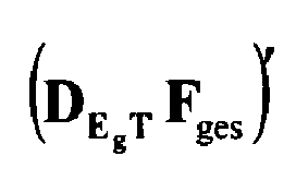


- It should be noted, however, that a direct use of the interpolation matrices C -1 and C 1 demands for high computer capacities. Therefore, it is preferred to approximate these matrices C -1 and C 1 by their respective main and secondary diagonals.
- If the output signals after echo compensation and/or other processing for noise reduction, dereverberation , etc., for the sub-bands that are not excised is denoted by ŝµ (n), where µ is the sub-band index, one obtains for all sub-bands (including the reconstruction of the previously excised sub-band vectors):

- It should be noted that reconstruction of a previously excised sub-band signal can be based on more than one preceding and subsequent sub-band signal (n-1 and n+2). In particular, a different number of preceding and subsequent sub-band signals may be used for the interpolation (C 0 ≠ 0).
- Synthesization of the thus obtained enhanced microphone sub-band signals in
step 6 ofFigure 1 is performed by means of a synthesis filter bank g µ,syn = └gµ,0,syn,...,gµ,Nsyn -1.syn┘T comprising, e.g., Hann windows, and also up-sampling the previously down-sampled sub-band signals again (by the same factor r above that was used for the down-sampling). -
Figure 2 shows an example of a realization of the herein disclosed method for signal processing. Consider a telephone conversation between a remote party and a near party that makes use of a hands-free set comprising a loudspeaker and a microphone. A signal from the remote party x(n) (reference signal) is received on the near side. The communication room of the near speaker, e.g., a vehicular compartment, represents a loudspeaker-room-microphone (LRM) system characterized by an impulse response h(n). The microphone of the LRM system is intended to detect a speech signal s(n) of the near side speaker. However, the microphone also detects background noise b(n) and an echo contribution d(n) caused by the loudspeaker output. The microphone signal generated by the microphone is thus given by y(n)= s(n) + b(n) + d(n). - The signal processing for quality enhancement in the present invention is performed in the sub-band regime. Thus, the microphone signal y(n) is filtered by an analysis filter bank g µ,ana 11 (s. above) in order to obtain microphone sub-band signals ysb(n). A particular number of sub-band signals is excised by a filtering means 12, e.g., each second sub-band signal, more particularly, sub-band signals of odd sub-bands. The resulting set of remaining sub-band signals of even sub-bands ysb, g (even index of the sub-bands) is subject to filtering for enhancing the signal quality. For example, noise reduction by means of a Wiener filter might be performed.
- In the example shown in
Figure 2 , the microphone sub-band signals of even sub-bands ysb, g (n) are filtered by an echo compensation filter
- In general, typical adaptation methods are iterative methods, i.e., in full band



- The corrector step is adjusted by means of the real number κ.
- Accordingly, in the sub-band regime the normalized least mean square (NLMS) algorithm reads


where the upper index H denotes the Hermitian adjugate. - Since the filtering means 12 only outputs signals for even sub-bands, the
echo compensation filter 13 also has only to operate for such sub-bands. Therefore, the reference signal x(n) is input in ananalysis filter bank 14 similar to the analysisfilter bank g µ,ana 11 used for dividing the microphone signal y(n) into sub-bands. From the resulting reference sub-band signals xsb(n) odd ones are excised as in the case of the microphone sub-band signals. Thus, theecho compensation filter 13 only receives even reference sub-band signals that are output by the filtering means 15 used to excise the other reference sub-band signals. For even sub-bands only error signals esb,g(n) are obtained that represent echo compensated microphone sub-band signals. - It should be noted that both the microphone sub-band signals and the reference signal sub-band signals are down-sampled by a factor r. For example, the spectra of the down-sampled reference sub-band signals are given by

- The higher the rate r is chosen, the more the computational load is reduced. However, due to the finite-slope filter flanks, r = M is an upper limit for the sampling rate r (where M is the number of sub-bands, i.e. number of channels of the
analysis filter banks 11 and 14). - In the example shown in
Figure 2 , the error signals esb,g(n) are further processed for noise reduction and reduction of residual echoes due to imperfect adaptation of theecho compensation filter 13 by a post-filtering means 16, e.g., a Wiener filter. The filter characteristics of the Wiener filter is adapted on the basis of the estimated auto power density of the error signals esb,g(n) and the perturbation that is still present in the error signals esb,g(n), i.e. the echo compensated microphone sub-band signals, in form of background noise and residual echoes (for details see, e.g., E. Hänsler and G. Schmidt, "Acoustic Echo and Noise Control - A Practical Approach", John Wiley & Sons, New York, 2004). - The enhanced sub-band signals ŝsb,g(n) are transferred from the post-filtering means 16 to a processing means 17 for reconstructing sub-band signals for the previously excised odd sub-bands. Reconstruction can be done as described above with reference to the flow chart of
Figure 1 . The complete set of sub-band signals s̃sb(n) is input in asynthesis filter bank 18 corresponding to the analysisfilter bank g µ,ana 14 used for the division of the microphone signal y(n) into the microphone sub-band signals ysb(n). Eventually, a full-band enhanced microphone signal s̃ (n) is obtained. - For a typical application including M = 256 sub-bands and down-sampling rates of r = 64 and r = 72, for example, according to the method of the present invention as described above both the computational time and memory demand can be reduced by about 50 % as compared to standard DFT processing. The time for signal processing (delay time) is only a few milliseconds above the time delay of standard processing by means of polyphase filter banks and, in particular, below the threshold according to the GSM standards of 39 ms in vehicular cabins. Moreover, the adaptation velocity of the
echo compensation filter 13 is only slightly different from the one in methods known in the art. - All previously discussed embodiments are not intended as limitations but serve as examples illustrating features and advantages of the invention. It is to be understood that some or all of the above described features can also be combined in different ways.
Claims (14)
- Method for audio signal processing, comprising
dividing a microphone signal (y(n)) into microphone sub-band signals ysb(n);
excising a predetermined number of the microphone sub-band signals ysb(n) for predetermined sub-bands;
processing the remaining microphone sub-band signals (ysb,g(n)) to obtain enhanced microphone sub-band signals (ŝsb,g(n)); and
reconstructing microphone sub-band signals for the predetermined sub-bands for which microphone sub-band signals were excised, wherein each of the excised microphone sub-band signals is reconstructed by means of enhanced microphone sub-band signals (ŝsb,g(n)) obtained by processing the remaining microphone sub-band signals (ysb,g(n)). - Method according to claim 1, wherein the processing of the remaining microphone sub-band signals (ysb,g(n)) to obtain the enhanced microphone sub-band signals (ŝsb,g(n)) comprises echo compensating and/or noise reduction of the remaining microphone sub-band signals (ysb,g(n)).
- Method according to claim 1 or 2, wherein the remaining microphone sub-band signals (ysb,g(n)) are echo compensated by steps comprising
dividing a reference signal (x(n)) into reference sub-band signals (xsb(n));
excising a predetermined number of the reference sub-band signals (xsb(n)) that is equal to the predetermined number of excised microphone sub-band signals for the same predetermined sub-bands;
adapting filter coefficients of an echo compensating filtering means based on the remaining reference sub-band signals (xsb,g(n)); and
filtering the remaining microphone sub-band signals (ysb,g(n)) by means of the adapted filter coefficients. - Method according to one of the preceding claims, wherein the predetermined number of sub-bands consists of sub-bands with an odd index or an even index and/or of sub-bands above or below some predetermined frequency.
- Method according to one of the preceding claims, wherein the microphone sub-band signals (ysb(n)) and the reference sub-band signals (xsb,g(n)) are down-sampled with respect to the microphone signal (y(n)) and the reference signal (x(n)), respectively, by the same down-sampling factor (r).
- Method according to one of the preceding claims, wherein at least at one time the microphone sub-band signals for the predetermined sub-bands for which microphone sub-band signals were excised are reconstructed for the predetermined sub-bands by averaging the remaining microphone sub-band signals that are adjacent in time.
- Method according to one of the preceding claims, wherein microphone sub-band signals for the predetermined sub-bands for which microphone sub-band signals were excised are reconstructed at a particular time (n) by interpolation of remaining microphone sub-band signals at the particular time (n) and remaining microphone sub-band signals that are adjacent in time.
- Method according to claim 7, wherein the interpolation is performed by interpolation matrices and wherein the interpolation matrices are approximated by their main diagonals and secondary diagonals, respectively.
- Computer program product, comprising one or more computer readable media having computer-executable instructions for performing the steps of the method according to one of the claims 1 - 8.
- Signal processing means, comprising
at least one microphone configured to obtain at least one microphone signal (y(n));
an analysis filter bank (11) configured to divide the at least one microphone signal (y(n)) into microphone sub-band signals ysb(n);
a first filtering means (12) configured to excise a predetermined number of the microphone sub-band signals ysb(n) for predetermined sub-bands;
a second filtering means (16) configured to process the remaining microphone sub-band signals (ysb,g(n)) to obtain enhanced microphone sub-band signals (ŝsb,g(n));
a processing means (17) configured to reconstruct microphone sub-band signals for the predetermined sub-bands for which microphone sub-band signals were excised by means of enhanced microphone sub-band signals (ŝsb,g(n)) obtained by processing the remaining microphone sub-band signals (ysb,g(n)); and
a synthesis filter bank (18) configured to synthesize the reconstructed and enhanced microphone sub-band signals (ŝsb (n)) obtained from the remaining microphone sub-band signals (ysb,g(n)) to obtain an enhanced microphone signal (s̃(n)). - The signal processing means according to claim 10, wherein the second filtering means (16) is an echo compensation filtering means; and further comprising
an analysis bank (14) configured to divide a reference signal into reference sub-band signals xsb(n);
a third filtering means (15) configured to excise a predetermined number of the reference sub-band signals xsb(n) that is equal to the predetermined number of excised microphone sub-band signals for the same predetermined sub-bands; and wherein
the echo compensation filtering means is configured to be adapted based on the remaining reference sub-band signals xsb,g(n) and to filter the remaining microphone sub-band signals (ysb,g(n)) by means of adapted filter coefficients. - The signal processing means according to claim 10 or 11, wherein the processing means (17) is configured to reconstruct microphone sub-band signals for the predetermined sub-bands for which microphone sub-band signals were excised at a particular time (n) by interpolation of remaining microphone sub-band signals at the particular time (n) and remaining microphone sub-band signals that are adjacent in time.
- The signal processing means according to one of the claims 10 - 12, further comprising a post-filtering means (17) configured to filter the enhanced microphone sub-band signals (ŝsb,g(n)) in order to reduce background noise and/or residual echoes.
- Hands-free telephone set or speech recognition means comprising a signal processing means according to one of the claims 10 - 13.
Priority Applications (5)
| Application Number | Priority Date | Filing Date | Title |
|---|---|---|---|
| AT07019281T ATE477572T1 (en) | 2007-10-01 | 2007-10-01 | EFFICIENT SUB-BAND AUDIO SIGNAL PROCESSING, METHOD, APPARATUS AND ASSOCIATED COMPUTER PROGRAM |
| EP07019281A EP2045801B1 (en) | 2007-10-01 | 2007-10-01 | Efficient audio signal processing in the sub-band regime, method, system and associated computer program |
| DE602007008429T DE602007008429D1 (en) | 2007-10-01 | 2007-10-01 | Efficient sub-band audio signal processing, method, apparatus and associated computer program |
| US12/241,788 US8320575B2 (en) | 2007-10-01 | 2008-09-30 | Efficient audio signal processing in the sub-band regime |
| US13/617,656 US9203972B2 (en) | 2007-10-01 | 2012-09-14 | Efficient audio signal processing in the sub-band regime |
Applications Claiming Priority (1)
| Application Number | Priority Date | Filing Date | Title |
|---|---|---|---|
| EP07019281A EP2045801B1 (en) | 2007-10-01 | 2007-10-01 | Efficient audio signal processing in the sub-band regime, method, system and associated computer program |
Publications (2)
| Publication Number | Publication Date |
|---|---|
| EP2045801A1 true EP2045801A1 (en) | 2009-04-08 |
| EP2045801B1 EP2045801B1 (en) | 2010-08-11 |
Family
ID=38670056
Family Applications (1)
| Application Number | Title | Priority Date | Filing Date |
|---|---|---|---|
| EP07019281A Ceased EP2045801B1 (en) | 2007-10-01 | 2007-10-01 | Efficient audio signal processing in the sub-band regime, method, system and associated computer program |
Country Status (4)
| Country | Link |
|---|---|
| US (2) | US8320575B2 (en) |
| EP (1) | EP2045801B1 (en) |
| AT (1) | ATE477572T1 (en) |
| DE (1) | DE602007008429D1 (en) |
Cited By (2)
| Publication number | Priority date | Publication date | Assignee | Title |
|---|---|---|---|---|
| US20090086986A1 (en) * | 2007-10-01 | 2009-04-02 | Gerhard Uwe Schmidt | Efficient audio signal processing in the sub-band regime |
| US11361779B2 (en) * | 2010-08-12 | 2022-06-14 | Fraunhofer-Gesellschaft Zur Foerderung Der Angewandten Forschung E.V. | Resampling output signals of QMF based audio codecs |
Families Citing this family (17)
| Publication number | Priority date | Publication date | Assignee | Title |
|---|---|---|---|---|
| US9286691B2 (en) * | 2009-04-17 | 2016-03-15 | The Hong Kong University Of Science And Technology | Motion estimation and compensation of feature-motion decorrelation |
| US9838784B2 (en) | 2009-12-02 | 2017-12-05 | Knowles Electronics, Llc | Directional audio capture |
| CN103069484B (en) * | 2010-04-14 | 2014-10-08 | 华为技术有限公司 | Time/frequency two dimension post-processing |
| US8538035B2 (en) | 2010-04-29 | 2013-09-17 | Audience, Inc. | Multi-microphone robust noise suppression |
| US8473287B2 (en) | 2010-04-19 | 2013-06-25 | Audience, Inc. | Method for jointly optimizing noise reduction and voice quality in a mono or multi-microphone system |
| US8781137B1 (en) | 2010-04-27 | 2014-07-15 | Audience, Inc. | Wind noise detection and suppression |
| US8447596B2 (en) | 2010-07-12 | 2013-05-21 | Audience, Inc. | Monaural noise suppression based on computational auditory scene analysis |
| US12002476B2 (en) | 2010-07-19 | 2024-06-04 | Dolby International Ab | Processing of audio signals during high frequency reconstruction |
| KR101964180B1 (en) | 2010-07-19 | 2019-04-01 | 돌비 인터네셔널 에이비 | Processing of audio signals during high frequency reconstruction |
| EP2562751B1 (en) * | 2011-08-22 | 2014-06-11 | Svox AG | Temporal interpolation of adjacent spectra |
| KR20140076894A (en) * | 2012-12-13 | 2014-06-23 | 삼성전자주식회사 | Method and apparatus for calculating channel quality adaptively in mobile communication system |
| US9536540B2 (en) | 2013-07-19 | 2017-01-03 | Knowles Electronics, Llc | Speech signal separation and synthesis based on auditory scene analysis and speech modeling |
| US9306606B2 (en) * | 2014-06-10 | 2016-04-05 | The Boeing Company | Nonlinear filtering using polyphase filter banks |
| WO2016040885A1 (en) | 2014-09-12 | 2016-03-17 | Audience, Inc. | Systems and methods for restoration of speech components |
| US9820042B1 (en) | 2016-05-02 | 2017-11-14 | Knowles Electronics, Llc | Stereo separation and directional suppression with omni-directional microphones |
| US10917074B2 (en) | 2019-03-29 | 2021-02-09 | Bose Corporation | Subband adaptive filter for systems with partially acausal transfer functions |
| CN116665717B (en) * | 2023-08-02 | 2023-09-29 | 广东技术师范大学 | Cross-subband spectral entropy weighted likelihood ratio voice detection method and system |
Citations (2)
| Publication number | Priority date | Publication date | Assignee | Title |
|---|---|---|---|---|
| US5272695A (en) * | 1990-09-14 | 1993-12-21 | Nippon Telegraph And Telephone Corporation | Subband echo canceller with adjustable coefficients using a series of step sizes |
| GB2426167A (en) | 2005-05-09 | 2006-11-15 | Toshiba Res Europ Ltd | Quantile based noise estimation |
Family Cites Families (17)
| Publication number | Priority date | Publication date | Assignee | Title |
|---|---|---|---|---|
| US5451954A (en) * | 1993-08-04 | 1995-09-19 | Dolby Laboratories Licensing Corporation | Quantization noise suppression for encoder/decoder system |
| US6504935B1 (en) * | 1998-08-19 | 2003-01-07 | Douglas L. Jackson | Method and apparatus for the modeling and synthesis of harmonic distortion |
| WO2000047014A1 (en) * | 1999-02-05 | 2000-08-10 | The University Of Melbourne | Adaptive dynamic range optimisation sound processor |
| US6898235B1 (en) * | 1999-12-10 | 2005-05-24 | Argon St Incorporated | Wideband communication intercept and direction finding device using hyperchannelization |
| JP3879922B2 (en) * | 2002-09-12 | 2007-02-14 | ソニー株式会社 | Signal processing system, signal processing apparatus and method, recording medium, and program |
| US20070071277A1 (en) * | 2003-05-28 | 2007-03-29 | Koninklijke Philips Electronics | Apparatus and method for embedding a watermark using sub-band filtering |
| EP1742509B1 (en) * | 2005-07-08 | 2013-08-14 | Oticon A/S | A system and method for eliminating feedback and noise in a hearing device |
| EP1918910B1 (en) * | 2006-10-31 | 2009-03-11 | Harman Becker Automotive Systems GmbH | Model-based enhancement of speech signals |
| US20080159551A1 (en) * | 2006-12-28 | 2008-07-03 | Texas Instruments Incorporated | System and Method for Acoustic Echo Removal (AER) |
| US8015368B2 (en) * | 2007-04-20 | 2011-09-06 | Siport, Inc. | Processor extensions for accelerating spectral band replication |
| DE602007008429D1 (en) * | 2007-10-01 | 2010-09-23 | Harman Becker Automotive Sys | Efficient sub-band audio signal processing, method, apparatus and associated computer program |
| DE602007004504D1 (en) * | 2007-10-29 | 2010-03-11 | Harman Becker Automotive Sys | Partial language reconstruction |
| EP2063419B1 (en) * | 2007-11-21 | 2012-04-18 | Nuance Communications, Inc. | Speaker localization |
| EP2222091B1 (en) * | 2009-02-23 | 2013-04-24 | Nuance Communications, Inc. | Method for determining a set of filter coefficients for an acoustic echo compensation means |
| EP2249333B1 (en) * | 2009-05-06 | 2014-08-27 | Nuance Communications, Inc. | Method and apparatus for estimating a fundamental frequency of a speech signal |
| US8908882B2 (en) * | 2009-06-29 | 2014-12-09 | Audience, Inc. | Reparation of corrupted audio signals |
| EP2562751B1 (en) * | 2011-08-22 | 2014-06-11 | Svox AG | Temporal interpolation of adjacent spectra |
-
2007
- 2007-10-01 DE DE602007008429T patent/DE602007008429D1/en active Active
- 2007-10-01 EP EP07019281A patent/EP2045801B1/en not_active Ceased
- 2007-10-01 AT AT07019281T patent/ATE477572T1/en not_active IP Right Cessation
-
2008
- 2008-09-30 US US12/241,788 patent/US8320575B2/en active Active
-
2012
- 2012-09-14 US US13/617,656 patent/US9203972B2/en active Active
Patent Citations (2)
| Publication number | Priority date | Publication date | Assignee | Title |
|---|---|---|---|---|
| US5272695A (en) * | 1990-09-14 | 1993-12-21 | Nippon Telegraph And Telephone Corporation | Subband echo canceller with adjustable coefficients using a series of step sizes |
| GB2426167A (en) | 2005-05-09 | 2006-11-15 | Toshiba Res Europ Ltd | Quantile based noise estimation |
Non-Patent Citations (4)
| Title |
|---|
| GAY S L ET AL: "Fast converging subband acoustic echo cancellation using RAP on the WE DSP16A", 3 April 1990, ICASSP, INTERNATIONAL CONFERENCE ON ACOUSTICS, SPEECH AND SIGNAL PROCESSING, PAGE(S) 1141-1144, XP010641486 * |
| LU XIAOJIAN ET AL., WORKSHOP ON APPLICATIONS OF SIGNAL PROCESSING TO AUDIO AND ACOUSTICS, 2003, IEEE, OCTOBER 29-22, 2003, NEW PLATZ, NY, USA, 19 October 2003 (2003-10-19), pages 29 - 32 |
| STEVEN L. GAY ET AL.: "Fast converging subband acoustic echo cancellation using RAP on the WE® DSP16A", ICASSP, INTERNATIONAL CONFERENCE ON ACOUSTICS, SPEECH AND SIGNAL PROCESSING, 3 April 1990 (1990-04-03), pages 1141 - 1144 |
| XIAOJIAN LU ET AL: "Acoustic echo cancellation with post-filtering in subband", APPLICATIONS OF SIGNAL PROCESSING TO AUDIO AND ACOUSTICS, 2003 IEEE WORKSHOP ON. NEW PALTZ, NY, USA OCT,. 19-22, 2003, PISCATAWAY, NJ, USA,IEEE, 19 October 2003 (2003-10-19), pages 29 - 32, XP010696434, ISBN: 0-7803-7850-4 * |
Cited By (12)
| Publication number | Priority date | Publication date | Assignee | Title |
|---|---|---|---|---|
| US20090086986A1 (en) * | 2007-10-01 | 2009-04-02 | Gerhard Uwe Schmidt | Efficient audio signal processing in the sub-band regime |
| US8320575B2 (en) * | 2007-10-01 | 2012-11-27 | Nuance Communications, Inc. | Efficient audio signal processing in the sub-band regime |
| US9203972B2 (en) | 2007-10-01 | 2015-12-01 | Nuance Communications, Inc. | Efficient audio signal processing in the sub-band regime |
| US11361779B2 (en) * | 2010-08-12 | 2022-06-14 | Fraunhofer-Gesellschaft Zur Foerderung Der Angewandten Forschung E.V. | Resampling output signals of QMF based audio codecs |
| US11475905B2 (en) | 2010-08-12 | 2022-10-18 | Fraunhofer-Gesellschaft Zur Foerderung Der Angewandten Forschung E.V. | Resampling output signals of QMF based audio codec |
| US11475906B2 (en) | 2010-08-12 | 2022-10-18 | Fraunhofer-Gesellschaft Zur Foerderung Der Angewandten Forschung E.V. | Resampling output signals of QMF based audio codec |
| US11676615B2 (en) | 2010-08-12 | 2023-06-13 | Fraunhofer-Gesellschaft Zur Foerderung Der Angewandten Forschung E.V. | Resampling output signals of QMF based audio codec |
| US11790928B2 (en) | 2010-08-12 | 2023-10-17 | Fraunhofer-Gesellschaft Zur Foerderung Der Angewandten Forschung E.V. | Resampling output signals of QMF based audio codecs |
| US11804232B2 (en) | 2010-08-12 | 2023-10-31 | Fraunhofer-Gesellschaft Zur Foerderung Der Angewandten Forschung E.V. | Resampling output signals of QMF based audio codecs |
| US11810584B2 (en) | 2010-08-12 | 2023-11-07 | Fraunhofer-Gesellschaft Zur Foerderung Der Angewandten Forschung E.V. | Resampling output signals of QMF based audio codecs |
| US11961531B2 (en) | 2010-08-12 | 2024-04-16 | Fraunhofer-Gesellschaft Zur Foerderung Der Angewandten Forschung E.V. | Resampling output signals of QMF based audio codec |
| US12154583B2 (en) | 2010-08-12 | 2024-11-26 | Fraunhofer-Gesellschaft Zur Foerderung Der Angewandten Forschung E.V. | Resampling output signals of QMF based audio codecs |
Also Published As
| Publication number | Publication date |
|---|---|
| US20090086986A1 (en) | 2009-04-02 |
| US20130010976A1 (en) | 2013-01-10 |
| US8320575B2 (en) | 2012-11-27 |
| DE602007008429D1 (en) | 2010-09-23 |
| US9203972B2 (en) | 2015-12-01 |
| ATE477572T1 (en) | 2010-08-15 |
| EP2045801B1 (en) | 2010-08-11 |
Similar Documents
| Publication | Publication Date | Title |
|---|---|---|
| EP2045801B1 (en) | Efficient audio signal processing in the sub-band regime, method, system and associated computer program | |
| EP1936939B1 (en) | Low complexity echo compensation | |
| EP1855457B1 (en) | Multi channel echo compensation using a decorrelation stage | |
| EP2048659B1 (en) | Gain and spectral shape adjustment in audio signal processing | |
| EP2905778B1 (en) | Echo cancellation method and device | |
| US8010355B2 (en) | Low complexity noise reduction method | |
| EP1855456B1 (en) | Echo reduction in time-variant systems | |
| KR101422984B1 (en) | Method and device for suppressing residual echoes | |
| EP2221983A1 (en) | Acoustic echo cancellation | |
| EP2562751B1 (en) | Temporal interpolation of adjacent spectra | |
| EP1718103B1 (en) | Compensation of reverberation and feedback | |
| CN102347028A (en) | Double-microphone speech enhancer and speech enhancement method thereof | |
| JP2001128282A (en) | Microphone array processing system for noisy multi-path environment | |
| EP1858295A1 (en) | Equalization in acoustic signal processing | |
| EP3274992B1 (en) | Adaptive audio filtering | |
| EP1927981B1 (en) | Spectral refinement of audio signals | |
| WO2006077934A1 (en) | Band division noise suppressor and band division noise suppressing method | |
| Krini et al. | Method for temporal interpolation of short-term spectra and its application to adaptive system identification | |
| JP2006203358A (en) | Echo cancellation circuit and mobile radio terminal device | |
| Hannon et al. | Reducing the Complexity or the Delay of Adaptive Subband Filtering. | |
| RU2485607C2 (en) | Apparatus and method for computing filter coefficients for echo suppression |
Legal Events
| Date | Code | Title | Description |
|---|---|---|---|
| PUAI | Public reference made under article 153(3) epc to a published international application that has entered the european phase |
Free format text: ORIGINAL CODE: 0009012 |
|
| AK | Designated contracting states |
Kind code of ref document: A1 Designated state(s): AT BE BG CH CY CZ DE DK EE ES FI FR GB GR HU IE IS IT LI LT LU LV MC MT NL PL PT RO SE SI SK TR |
|
| AX | Request for extension of the european patent |
Extension state: AL BA HR MK RS |
|
| 17P | Request for examination filed |
Effective date: 20090428 |
|
| 17Q | First examination report despatched |
Effective date: 20090602 |
|
| AKX | Designation fees paid |
Designated state(s): AT BE BG CH CY CZ DE DK EE ES FI FR GB GR HU IE IS IT LI LT LU LV MC MT NL PL PT RO SE SI SK TR |
|
| GRAP | Despatch of communication of intention to grant a patent |
Free format text: ORIGINAL CODE: EPIDOSNIGR1 |
|
| RTI1 | Title (correction) |
Free format text: EFFICIENT AUDIO SIGNAL PROCESSING IN THE SUB-BAND REGIME, METHOD, SYSTEM AND ASSOCIATED COMPUTER PROGRAM |
|
| GRAS | Grant fee paid |
Free format text: ORIGINAL CODE: EPIDOSNIGR3 |
|
| GRAA | (expected) grant |
Free format text: ORIGINAL CODE: 0009210 |
|
| AK | Designated contracting states |
Kind code of ref document: B1 Designated state(s): AT BE BG CH CY CZ DE DK EE ES FI FR GB GR HU IE IS IT LI LT LU LV MC MT NL PL PT RO SE SI SK TR |
|
| REG | Reference to a national code |
Ref country code: GB Ref legal event code: FG4D |
|
| REG | Reference to a national code |
Ref country code: CH Ref legal event code: EP |
|
| REG | Reference to a national code |
Ref country code: IE Ref legal event code: FG4D |
|
| REF | Corresponds to: |
Ref document number: 602007008429 Country of ref document: DE Date of ref document: 20100923 Kind code of ref document: P |
|
| REG | Reference to a national code |
Ref country code: NL Ref legal event code: VDEP Effective date: 20100811 |
|
| LTIE | Lt: invalidation of european patent or patent extension |
Effective date: 20100811 |
|
| PG25 | Lapsed in a contracting state [announced via postgrant information from national office to epo] |
Ref country code: LT Free format text: LAPSE BECAUSE OF FAILURE TO SUBMIT A TRANSLATION OF THE DESCRIPTION OR TO PAY THE FEE WITHIN THE PRESCRIBED TIME-LIMIT Effective date: 20100811 Ref country code: NL Free format text: LAPSE BECAUSE OF FAILURE TO SUBMIT A TRANSLATION OF THE DESCRIPTION OR TO PAY THE FEE WITHIN THE PRESCRIBED TIME-LIMIT Effective date: 20100811 Ref country code: FI Free format text: LAPSE BECAUSE OF FAILURE TO SUBMIT A TRANSLATION OF THE DESCRIPTION OR TO PAY THE FEE WITHIN THE PRESCRIBED TIME-LIMIT Effective date: 20100811 Ref country code: AT Free format text: LAPSE BECAUSE OF FAILURE TO SUBMIT A TRANSLATION OF THE DESCRIPTION OR TO PAY THE FEE WITHIN THE PRESCRIBED TIME-LIMIT Effective date: 20100811 |
|
| PG25 | Lapsed in a contracting state [announced via postgrant information from national office to epo] |
Ref country code: PL Free format text: LAPSE BECAUSE OF FAILURE TO SUBMIT A TRANSLATION OF THE DESCRIPTION OR TO PAY THE FEE WITHIN THE PRESCRIBED TIME-LIMIT Effective date: 20100811 Ref country code: IS Free format text: LAPSE BECAUSE OF FAILURE TO SUBMIT A TRANSLATION OF THE DESCRIPTION OR TO PAY THE FEE WITHIN THE PRESCRIBED TIME-LIMIT Effective date: 20101211 Ref country code: CY Free format text: LAPSE BECAUSE OF FAILURE TO SUBMIT A TRANSLATION OF THE DESCRIPTION OR TO PAY THE FEE WITHIN THE PRESCRIBED TIME-LIMIT Effective date: 20100811 Ref country code: SI Free format text: LAPSE BECAUSE OF FAILURE TO SUBMIT A TRANSLATION OF THE DESCRIPTION OR TO PAY THE FEE WITHIN THE PRESCRIBED TIME-LIMIT Effective date: 20100811 Ref country code: PT Free format text: LAPSE BECAUSE OF FAILURE TO SUBMIT A TRANSLATION OF THE DESCRIPTION OR TO PAY THE FEE WITHIN THE PRESCRIBED TIME-LIMIT Effective date: 20101213 Ref country code: BG Free format text: LAPSE BECAUSE OF FAILURE TO SUBMIT A TRANSLATION OF THE DESCRIPTION OR TO PAY THE FEE WITHIN THE PRESCRIBED TIME-LIMIT Effective date: 20101111 |
|
| PG25 | Lapsed in a contracting state [announced via postgrant information from national office to epo] |
Ref country code: SE Free format text: LAPSE BECAUSE OF FAILURE TO SUBMIT A TRANSLATION OF THE DESCRIPTION OR TO PAY THE FEE WITHIN THE PRESCRIBED TIME-LIMIT Effective date: 20100811 Ref country code: LV Free format text: LAPSE BECAUSE OF FAILURE TO SUBMIT A TRANSLATION OF THE DESCRIPTION OR TO PAY THE FEE WITHIN THE PRESCRIBED TIME-LIMIT Effective date: 20100811 Ref country code: GR Free format text: LAPSE BECAUSE OF FAILURE TO SUBMIT A TRANSLATION OF THE DESCRIPTION OR TO PAY THE FEE WITHIN THE PRESCRIBED TIME-LIMIT Effective date: 20101112 Ref country code: BE Free format text: LAPSE BECAUSE OF FAILURE TO SUBMIT A TRANSLATION OF THE DESCRIPTION OR TO PAY THE FEE WITHIN THE PRESCRIBED TIME-LIMIT Effective date: 20100811 |
|
| PG25 | Lapsed in a contracting state [announced via postgrant information from national office to epo] |
Ref country code: DK Free format text: LAPSE BECAUSE OF FAILURE TO SUBMIT A TRANSLATION OF THE DESCRIPTION OR TO PAY THE FEE WITHIN THE PRESCRIBED TIME-LIMIT Effective date: 20100811 |
|
| PG25 | Lapsed in a contracting state [announced via postgrant information from national office to epo] |
Ref country code: CZ Free format text: LAPSE BECAUSE OF FAILURE TO SUBMIT A TRANSLATION OF THE DESCRIPTION OR TO PAY THE FEE WITHIN THE PRESCRIBED TIME-LIMIT Effective date: 20100811 Ref country code: IT Free format text: LAPSE BECAUSE OF FAILURE TO SUBMIT A TRANSLATION OF THE DESCRIPTION OR TO PAY THE FEE WITHIN THE PRESCRIBED TIME-LIMIT Effective date: 20100811 Ref country code: RO Free format text: LAPSE BECAUSE OF FAILURE TO SUBMIT A TRANSLATION OF THE DESCRIPTION OR TO PAY THE FEE WITHIN THE PRESCRIBED TIME-LIMIT Effective date: 20100811 Ref country code: SK Free format text: LAPSE BECAUSE OF FAILURE TO SUBMIT A TRANSLATION OF THE DESCRIPTION OR TO PAY THE FEE WITHIN THE PRESCRIBED TIME-LIMIT Effective date: 20100811 Ref country code: MC Free format text: LAPSE BECAUSE OF NON-PAYMENT OF DUE FEES Effective date: 20101031 Ref country code: EE Free format text: LAPSE BECAUSE OF FAILURE TO SUBMIT A TRANSLATION OF THE DESCRIPTION OR TO PAY THE FEE WITHIN THE PRESCRIBED TIME-LIMIT Effective date: 20100811 |
|
| PLBE | No opposition filed within time limit |
Free format text: ORIGINAL CODE: 0009261 |
|
| STAA | Information on the status of an ep patent application or granted ep patent |
Free format text: STATUS: NO OPPOSITION FILED WITHIN TIME LIMIT |
|
| PG25 | Lapsed in a contracting state [announced via postgrant information from national office to epo] |
Ref country code: ES Free format text: LAPSE BECAUSE OF FAILURE TO SUBMIT A TRANSLATION OF THE DESCRIPTION OR TO PAY THE FEE WITHIN THE PRESCRIBED TIME-LIMIT Effective date: 20101122 |
|
| 26N | No opposition filed |
Effective date: 20110512 |
|
| REG | Reference to a national code |
Ref country code: DE Ref legal event code: R097 Ref document number: 602007008429 Country of ref document: DE Effective date: 20110512 |
|
| PG25 | Lapsed in a contracting state [announced via postgrant information from national office to epo] |
Ref country code: IE Free format text: LAPSE BECAUSE OF NON-PAYMENT OF DUE FEES Effective date: 20101001 |
|
| PG25 | Lapsed in a contracting state [announced via postgrant information from national office to epo] |
Ref country code: MT Free format text: LAPSE BECAUSE OF FAILURE TO SUBMIT A TRANSLATION OF THE DESCRIPTION OR TO PAY THE FEE WITHIN THE PRESCRIBED TIME-LIMIT Effective date: 20100811 |
|
| REG | Reference to a national code |
Ref country code: DE Ref legal event code: R082 Ref document number: 602007008429 Country of ref document: DE Representative=s name: GRUENECKER, KINKELDEY, STOCKMAIR & SCHWANHAEUS, DE |
|
| REG | Reference to a national code |
Ref country code: DE Ref legal event code: R082 Ref document number: 602007008429 Country of ref document: DE Representative=s name: GRUENECKER, KINKELDEY, STOCKMAIR & SCHWANHAEUS, DE Effective date: 20120411 Ref country code: DE Ref legal event code: R081 Ref document number: 602007008429 Country of ref document: DE Owner name: NUANCE COMMUNICATIONS, INC. (N.D.GES.D. STAATE, US Free format text: FORMER OWNER: HARMAN BECKER AUTOMOTIVE SYSTEMS GMBH, 76307 KARLSBAD, DE Effective date: 20120411 Ref country code: DE Ref legal event code: R082 Ref document number: 602007008429 Country of ref document: DE Representative=s name: GRUENECKER PATENT- UND RECHTSANWAELTE PARTG MB, DE Effective date: 20120411 Ref country code: CH Ref legal event code: PL |
|
| PG25 | Lapsed in a contracting state [announced via postgrant information from national office to epo] |
Ref country code: LI Free format text: LAPSE BECAUSE OF NON-PAYMENT OF DUE FEES Effective date: 20111031 Ref country code: CH Free format text: LAPSE BECAUSE OF NON-PAYMENT OF DUE FEES Effective date: 20111031 |
|
| PG25 | Lapsed in a contracting state [announced via postgrant information from national office to epo] |
Ref country code: HU Free format text: LAPSE BECAUSE OF FAILURE TO SUBMIT A TRANSLATION OF THE DESCRIPTION OR TO PAY THE FEE WITHIN THE PRESCRIBED TIME-LIMIT Effective date: 20110212 Ref country code: LU Free format text: LAPSE BECAUSE OF NON-PAYMENT OF DUE FEES Effective date: 20101001 |
|
| REG | Reference to a national code |
Ref country code: FR Ref legal event code: TP Owner name: NUANCE COMMUNICATIONS, INC., US Effective date: 20120924 |
|
| PG25 | Lapsed in a contracting state [announced via postgrant information from national office to epo] |
Ref country code: TR Free format text: LAPSE BECAUSE OF FAILURE TO SUBMIT A TRANSLATION OF THE DESCRIPTION OR TO PAY THE FEE WITHIN THE PRESCRIBED TIME-LIMIT Effective date: 20100811 |
|
| REG | Reference to a national code |
Ref country code: FR Ref legal event code: PLFP Year of fee payment: 10 |
|
| REG | Reference to a national code |
Ref country code: FR Ref legal event code: PLFP Year of fee payment: 11 |
|
| REG | Reference to a national code |
Ref country code: FR Ref legal event code: PLFP Year of fee payment: 12 |
|
| PGFP | Annual fee paid to national office [announced via postgrant information from national office to epo] |
Ref country code: FR Payment date: 20181025 Year of fee payment: 12 Ref country code: GB Payment date: 20181031 Year of fee payment: 12 |
|
| PGFP | Annual fee paid to national office [announced via postgrant information from national office to epo] |
Ref country code: DE Payment date: 20181228 Year of fee payment: 12 |
|
| REG | Reference to a national code |
Ref country code: DE Ref legal event code: R119 Ref document number: 602007008429 Country of ref document: DE |
|
| PG25 | Lapsed in a contracting state [announced via postgrant information from national office to epo] |
Ref country code: DE Free format text: LAPSE BECAUSE OF NON-PAYMENT OF DUE FEES Effective date: 20200501 |
|
| GBPC | Gb: european patent ceased through non-payment of renewal fee |
Effective date: 20191001 |
|
| PG25 | Lapsed in a contracting state [announced via postgrant information from national office to epo] |
Ref country code: FR Free format text: LAPSE BECAUSE OF NON-PAYMENT OF DUE FEES Effective date: 20191031 Ref country code: GB Free format text: LAPSE BECAUSE OF NON-PAYMENT OF DUE FEES Effective date: 20191001 |