EP2045482A1 - Disc brake device, spring and vehicle and using such a disc brake device or spring - Google Patents
Disc brake device, spring and vehicle and using such a disc brake device or spring Download PDFInfo
- Publication number
- EP2045482A1 EP2045482A1 EP08165826A EP08165826A EP2045482A1 EP 2045482 A1 EP2045482 A1 EP 2045482A1 EP 08165826 A EP08165826 A EP 08165826A EP 08165826 A EP08165826 A EP 08165826A EP 2045482 A1 EP2045482 A1 EP 2045482A1
- Authority
- EP
- European Patent Office
- Prior art keywords
- brake
- spring
- lining
- disc
- yoke
- Prior art date
- Legal status (The legal status is an assumption and is not a legal conclusion. Google has not performed a legal analysis and makes no representation as to the accuracy of the status listed.)
- Granted
Links
- 230000033001 locomotion Effects 0.000 claims description 17
- 239000000463 material Substances 0.000 claims description 11
- 230000008859 change Effects 0.000 description 4
- 230000007246 mechanism Effects 0.000 description 4
- 238000004026 adhesive bonding Methods 0.000 description 2
- 230000008901 benefit Effects 0.000 description 2
- 239000004020 conductor Substances 0.000 description 2
- 238000010586 diagram Methods 0.000 description 2
- 230000000694 effects Effects 0.000 description 2
- 238000005476 soldering Methods 0.000 description 2
- 230000002411 adverse Effects 0.000 description 1
- 230000007613 environmental effect Effects 0.000 description 1
- 239000000446 fuel Substances 0.000 description 1
- 238000000034 method Methods 0.000 description 1
- 230000004048 modification Effects 0.000 description 1
- 238000012986 modification Methods 0.000 description 1
- 230000008569 process Effects 0.000 description 1
- 239000000725 suspension Substances 0.000 description 1
Images


Classifications
-
- F—MECHANICAL ENGINEERING; LIGHTING; HEATING; WEAPONS; BLASTING
- F16—ENGINEERING ELEMENTS AND UNITS; GENERAL MEASURES FOR PRODUCING AND MAINTAINING EFFECTIVE FUNCTIONING OF MACHINES OR INSTALLATIONS; THERMAL INSULATION IN GENERAL
- F16D—COUPLINGS FOR TRANSMITTING ROTATION; CLUTCHES; BRAKES
- F16D65/00—Parts or details
- F16D65/02—Braking members; Mounting thereof
- F16D65/04—Bands, shoes or pads; Pivots or supporting members therefor
- F16D65/092—Bands, shoes or pads; Pivots or supporting members therefor for axially-engaging brakes, e.g. disc brakes
- F16D65/095—Pivots or supporting members therefor
- F16D65/097—Resilient means interposed between pads and supporting members or other brake parts
- F16D65/0973—Resilient means interposed between pads and supporting members or other brake parts not subjected to brake forces
- F16D65/0974—Resilient means interposed between pads and supporting members or other brake parts not subjected to brake forces acting on or in the vicinity of the pad rim in a direction substantially transverse to the brake disc axis
- F16D65/0975—Springs made from wire
- F16D65/0976—Springs made from wire acting on one pad only
-
- F—MECHANICAL ENGINEERING; LIGHTING; HEATING; WEAPONS; BLASTING
- F16—ENGINEERING ELEMENTS AND UNITS; GENERAL MEASURES FOR PRODUCING AND MAINTAINING EFFECTIVE FUNCTIONING OF MACHINES OR INSTALLATIONS; THERMAL INSULATION IN GENERAL
- F16D—COUPLINGS FOR TRANSMITTING ROTATION; CLUTCHES; BRAKES
- F16D65/00—Parts or details
- F16D65/02—Braking members; Mounting thereof
- F16D65/04—Bands, shoes or pads; Pivots or supporting members therefor
- F16D65/092—Bands, shoes or pads; Pivots or supporting members therefor for axially-engaging brakes, e.g. disc brakes
- F16D65/095—Pivots or supporting members therefor
- F16D65/097—Resilient means interposed between pads and supporting members or other brake parts
- F16D65/0973—Resilient means interposed between pads and supporting members or other brake parts not subjected to brake forces
- F16D65/0974—Resilient means interposed between pads and supporting members or other brake parts not subjected to brake forces acting on or in the vicinity of the pad rim in a direction substantially transverse to the brake disc axis
-
- F—MECHANICAL ENGINEERING; LIGHTING; HEATING; WEAPONS; BLASTING
- F16—ENGINEERING ELEMENTS AND UNITS; GENERAL MEASURES FOR PRODUCING AND MAINTAINING EFFECTIVE FUNCTIONING OF MACHINES OR INSTALLATIONS; THERMAL INSULATION IN GENERAL
- F16D—COUPLINGS FOR TRANSMITTING ROTATION; CLUTCHES; BRAKES
- F16D66/00—Arrangements for monitoring working conditions, e.g. wear, temperature
- F16D66/02—Apparatus for indicating wear
-
- F—MECHANICAL ENGINEERING; LIGHTING; HEATING; WEAPONS; BLASTING
- F16—ENGINEERING ELEMENTS AND UNITS; GENERAL MEASURES FOR PRODUCING AND MAINTAINING EFFECTIVE FUNCTIONING OF MACHINES OR INSTALLATIONS; THERMAL INSULATION IN GENERAL
- F16D—COUPLINGS FOR TRANSMITTING ROTATION; CLUTCHES; BRAKES
- F16D66/00—Arrangements for monitoring working conditions, e.g. wear, temperature
- F16D2066/003—Position, angle or speed
-
- F—MECHANICAL ENGINEERING; LIGHTING; HEATING; WEAPONS; BLASTING
- F16—ENGINEERING ELEMENTS AND UNITS; GENERAL MEASURES FOR PRODUCING AND MAINTAINING EFFECTIVE FUNCTIONING OF MACHINES OR INSTALLATIONS; THERMAL INSULATION IN GENERAL
- F16D—COUPLINGS FOR TRANSMITTING ROTATION; CLUTCHES; BRAKES
- F16D2127/00—Auxiliary mechanisms
- F16D2127/02—Release mechanisms
Definitions
- the present invention relates to a disc brake device and a spring.
- the invention also relates to a vehicle provided with such a disc brake device or spring and also the use of such a disc brake device or spring.
- disc brakes are used for braking the rotary motion of a wheel about a wheel shaft on a vehicle.
- a typical disc brake on a vehicle comprises a brake yoke adapted to gripping about a brake disc connected to the wheel shaft, and to varying the braking force by variation of the gripping force.
- the brake yoke comprises often, but not always, a lining carrier mounted firmly on some non-rotating part of the wheel suspension, and a yoke saddle supported for axial and linear movement on the lining carrier.
- the brake linings rest on the lining carrier on each side of the brake disc and are surrounded by the yoke saddle, and a brake piston adapted to controllably pressing the brake linings together about the brake disc is arranged in the yoke saddle.
- a reason for the yoke saddle being supported for linear movement along the shaft is that the yoke saddle often lacks brake pistons on one side of the brake disc.
- the yoke saddle being movable means that substantially equal forces are exerted on the brake disc by the brake linings on each side of the brake disc, and the brake linings will in the ideal case wear equally on each side of the brake disc. This is desirable in that changing all the brake linings of a brake on the same occasion is less expensive.
- An automatic adjustment mechanism ensures that the clearance between the brake linings and the brake disc as the linings wear remains small.
- the automatic adjustment mechanism rotates an adjusting screw which reduces the clearance if a predetermined maximum retraction movement is exceeded when the brake pistons move back after a brake application.
- Another problem which may arise is that the linings do not retract far enough when the brake is released, e.g. a clearance may arise between a brake lining and the corresponding brake piston instead of between the brake lining and the disc. If this occurs, the brake lining continually abuts against the brake disc, hampering the fuel economics and causing adverse environmental effects and increasing the risk of the linings wearing unevenly.
- Brake linings are usually changed via an assembly aperture in the yoke saddle.
- a brake lining spring is adapted to exerting a parting spring force between the cover/lining retainer and a brake lining in order to press the lining against the lining carrier in the direction towards the shaft.
- the main functions of the brake lining spring are to prevent the lining from vibrating and moving in the yoke saddle when the vehicle is in motion, and to create a suitable hysteresis in the yoke saddle's axial movement relative to the lining carrier in order to prevent the linings coming into contact with the brake disc when no braking force is applied across the disc.
- An object of the invention is to propose a novel disc brake device which indicates when it is time to change brake linings and which reduces the risk of the brake linings abutting against the brake disc even when the brake is not applied.
- a disc brake device comprising a brake disc with two opposite friction surfaces and adapted to being connected to a rotatable shaft; and a brake yoke adapted to being connected to a non-rotatable part of a machine or vehicle, and to moving freely from the brake disc and straddling the brake disc with two sidepieces comprised in the brake yoke and each having an extent along part of the respective friction surface; said brake yoke being further provided with brake linings and a brake piston which is arranged in a sidepiece and is adapted to controllably pressing the brake lining against the brake disc,
- which disc brake device comprises an indicator spring adapted to being tensioned upon the fitting of a brake lining, which indicator spring comprises a sacrificial portion adapted to being connected to the brake lining and having an extent such that the sacrificial portion is worn away by rubbing against the brake disc or, alternatively, is worn free from a fastening in the wearing material of the brake lining, when the wear on the
- a disc brake device comprising a brake disc with two opposite friction surfaces and adapted to being connected to a rotatable shaft; and a brake yoke adapted to being connected to a non-rotatable part of a machine or vehicle, and to moving freely from the brake disc and straddling the brake disc with two sidepieces comprised in the brake yoke which each have an extent along part of the respective friction surface; said brake yoke being further provided with brake linings and a brake piston which is arranged in a sidepiece and is adapted to controllably pressing the brake lining against the brake disc, which disc brake device comprises a return spring adapted to pulling or pushing the linings apart in the axial direction.
- the return spring and the indicator spring take the form with advantage of one and the same spring component, since this minimises the number of components of the brake device.
- the number of components may be further reduced by the spring being adapted to pushing a brake lining radially towards the shaft.
- the spring may take the form of, for example, a wire spring, since such a spring makes it easier to achieve springing in a number of different directions and to combine a number of different spring functions in one and the same component, but it is also possible, for example, for a leaf spring to be configured in such a way as to combine the desired characteristics in a single component.
- any possible drawer effect can be reduced by the spring's abutment surfaces against the lining being arranged as far as possible from one another; the drawer effect is also further reduced by the spring forces with which the abutment surfaces of the spring press on the brake lining being substantially independent of one another.
- the invention is not limited to braking the rotary motion of a wheel shaft; brake yokes in combination with brake discs are also used for braking other motions, whether rotary or linear, e.g. in other machines than vehicles. Such applications also fall within the scope of the concept of the invention and are therefore covered by the attached claims. Other features and advantages of the invention may be indicated by the claims and the description of embodiment examples set out below.
- FIG. 1 depicts an example of an embodiment of a disc brake device according to the invention.
- a disc brake device 10 is fitted to, and adapted to braking, a wheel shaft 12.
- the disc brake device 10 comprises a brake disc 14 mounted on the wheel shaft 12, and a brake yoke 16 fitted non-rotatably and adapted to gripping with controllable force about the brake disc 14.
- the brake yoke 16 in FIG. 2 comprises a lining carrier 18 on which a first and a second brake lining 20, 22 rest.
- a yoke saddle 24 which surrounds the brake linings 20, 22 rests above, and is axially supported for movement in the lining carrier 18.
- a brake piston 26 is adapted, upon brake application, to pressing the first brake lining 20 against the brake disc 14, whereupon corresponding reaction forces push the yoke saddle 24 and hence the second brake lining 22 with substantially the same force in the other direction, i.e. towards the other side of the brake disc 14.
- In the upper portion of the yoke saddle 24 there is an assembly aperture 28 ( FIG. 1 ) which makes it possible to change the brake linings 20, 22 without removing the brake yoke 16.
- a removable lining retainer 30 adapted, with a brake lining spring 32 which is fastened to the lining retainer 30 and takes the form of a leaf spring, to pushing the brake lining 20 radially towards the shaft 12 and axially away from the disc 14.
- a tab ( FIGS. 4A-B ) on the leaf spring 32 is adapted to indicating when the wear on the brake lining 20 reaches a predetermined level.
- a corresponding leaf spring 31 for the lining 22 is also depicted in the diagram.
- FIG. 3 depicts an example of how a brake lining spring 31, 32 may be configured.
- a bent portion 35 in the form of an undercut trapezoidal profile allows a releasable connection relative to the lining retainer.
- the spring 32 is bent in such a way that it is adapted to pushing a lining 20 both downwards (arrow 1) and axially (arrow 2).
- the axial force is provided, for example, by the respective arms of the spring being somewhat rotated or by the bent portion 35 giving them a slope relative to the plane of the lining retainer.
- the spring 32 is further provided with a curved tab (not depicted in FIG. 3 ), the configuration and function of which are illustrated in more detail in FIGS. 4A-B .
- FIGS. 4A-B are detail views of an embodiment of a spring 32 which comprises a tab with indicator function.
- FIG. 4A depicts the spring in a tensioned state.
- a sacrificial portion belonging to the spring 32 is connected to the brake lining 20 in such a way that when the connection is worn away against the brake disc 14, the spring 32 will describe a springing movement whereby an indicator element 38 will spring out through the assembly aperture 28 of the brake piston and indicate that the brake lining 20 has reached a predetermined wear level.
- the connection may be by adhesive bonding or soldering, a tab on the brake lining being adapted to hooking firmly in a bend in the sacrificial portion of the spring, or some other suitable connection.
- FIG. 5 depicts another example of an embodiment of a disc brake device according to the invention, in which the springs 31, 32 take the form of wire springs.
- One end of each wire spring 31, 32 runs down through a hole in the respective brake lining 22, 20 and up again to abut and press against the lining retainer 30.
- FIG. 6A is a view from above of an unloaded spring 32 according to the embodiment in FIG. 5 .
- this spring 32 a brake lining 20 and the lining retainer 30 are raised from the yoke 16 to illustrate more clearly the function of the spring 32 in cooperation with the lining retainer 30 and the lining 20.
- the wire spring 32 is curved in a double arc in which the respective end of the arc is adapted to abutting against the brake lining 20 and to springingly pushing it radially in the direction towards the shaft (the arrows in FIG. 6C ) and axially away from the disc (the arrows in 6B).
- the wire spring 32 further has a section 34 adapted to surrounding, and connecting the spring 32 to, the lining retainer 30; a sacrificial section 36 adapted to running down through a hole 33 in the wearing material of the brake lining 20; an indicator section 38 and a section 40 adapted to being tensioned and springingly abutting and pressing up against the lining retainer 30.
- the lining retainer 30 In the assembled state ( FIGS. 6B-C ) the lining retainer 30 will, via the section 40, hold down the indicator section 38 which would otherwise, owing to the tensioning of the spring, endeavour to move away from the shaft 12 ( FIG. 5 ).
- the indicator section 38 springs up and indicates that the brake lining 20 has reached a predetermined worn-down level.
- the indicator element or indicator section may be adapted to springing up through an indicating hole in the cover, but the indication may be read in many ways, e.g. visually, mechanically, optically or electromechanically.
- the indication may also be connected to a warning lamp in the vehicle's instrument panel, to the vehicle's computer or by radio to, for example, a service station.
- a brake lining spring in the form of a leaf spring may be combined with an indicator spring in the form of a leaf, wire or coil spring provided with a sacrificial section and/or an abradable connection to a lining.
- the spring need not necessarily be connected to the lining retainer by surrounding it as illustrated in the diagrams. It may be connected in some other way, e.g. by a fastening device, or be connected to some other part of the yoke. In fact, it is not even necessary that the spring be connected to the yoke; it may instead be fastened to, for example, the brake lining, or be tensioned in the space between the brake lining and some point on the yoke by its own tensioning force. Nor is it necessary that the spring be worn away in order to achieve an indicator function; other embodiments may for example comprise the spring being worn free from a fastening, e.g.
- the fastening need not be arranged through a hole in the wearing material, as it may equally well be arranged in a slit or on an edge of the wearing material at a position situated at a suitable distance from the lining plate on which the wearing material is arranged.
- the lining retainer be configured as illustrated; it may also take other forms, e.g. that of a cover covering the whole of the assembly aperture, and/or be provided with various kinds of means for releasable connection to a brake lining spring/indicator spring/return spring.
Landscapes
- Engineering & Computer Science (AREA)
- General Engineering & Computer Science (AREA)
- Mechanical Engineering (AREA)
- Braking Arrangements (AREA)
Abstract
Description
- The present invention relates to a disc brake device and a spring.
- The invention also relates to a vehicle provided with such a disc brake device or spring and also the use of such a disc brake device or spring.
- In many different machines there is a need to brake a rotary motion, e.g. disc brakes are used for braking the rotary motion of a wheel about a wheel shaft on a vehicle.
- A typical disc brake on a vehicle comprises a brake yoke adapted to gripping about a brake disc connected to the wheel shaft, and to varying the braking force by variation of the gripping force. The brake yoke comprises often, but not always, a lining carrier mounted firmly on some non-rotating part of the wheel suspension, and a yoke saddle supported for axial and linear movement on the lining carrier. The brake linings rest on the lining carrier on each side of the brake disc and are surrounded by the yoke saddle, and a brake piston adapted to controllably pressing the brake linings together about the brake disc is arranged in the yoke saddle. A reason for the yoke saddle being supported for linear movement along the shaft is that the yoke saddle often lacks brake pistons on one side of the brake disc. The yoke saddle being movable means that substantially equal forces are exerted on the brake disc by the brake linings on each side of the brake disc, and the brake linings will in the ideal case wear equally on each side of the brake disc. This is desirable in that changing all the brake linings of a brake on the same occasion is less expensive.
- An automatic adjustment mechanism ensures that the clearance between the brake linings and the brake disc as the linings wear remains small. The automatic adjustment mechanism rotates an adjusting screw which reduces the clearance if a predetermined maximum retraction movement is exceeded when the brake pistons move back after a brake application.
- Unfortunately, it sometimes happens that one of two opposite brake linings wears more quickly than the other. The result is non-optimum use of the wearing capacity of the linings, since both of the linings in a yoke or even, generally, all of the linings on a shaft are, for practical reasons, changed at the same time.
- As taking wheels off and opening brake yoke covers to inspect the wear state of brake linings is a laborious process, various solutions have been developed for indicating when it is time to change linings. For example, using an electrical conductor which runs through the wearing material of a brake lining has been tried. When the lining wears down to the electrical conductor and the latter comes into contact with the brake disc, the result is an electrical indication that it is time to change the lining concerned. This device is very rarely used, since the tough environment at the wheel, involving vibrations, moisture and dirt, results in its producing an unreliable signal.
- The most commonly used solution today is to have on the automatic adjustment mechanism of the brake yoke an electronic sensor device which measures how many revolutions the aforesaid adjusting screw has turned. Although this device is very reliable, it nevertheless has a shortcoming in that since it is the total lining wear on both of the linings of a disc brake that is measured, the linings have to be inspected manually in the workshop as early as when 50% of the combined wearing capacity of the two linings has worn away, in case the linings have for any reason not worn equally.
- Another problem which may arise is that the linings do not retract far enough when the brake is released, e.g. a clearance may arise between a brake lining and the corresponding brake piston instead of between the brake lining and the disc. If this occurs, the brake lining continually abuts against the brake disc, hampering the fuel economics and causing adverse environmental effects and increasing the risk of the linings wearing unevenly.
- Brake linings are usually changed via an assembly aperture in the yoke saddle. Typically there is some form of cover and/or lining retainer mechanism over the assembly aperture, and a brake lining spring is adapted to exerting a parting spring force between the cover/lining retainer and a brake lining in order to press the lining against the lining carrier in the direction towards the shaft. The main functions of the brake lining spring are to prevent the lining from vibrating and moving in the yoke saddle when the vehicle is in motion, and to create a suitable hysteresis in the yoke saddle's axial movement relative to the lining carrier in order to prevent the linings coming into contact with the brake disc when no braking force is applied across the disc.
- An object of the invention is to propose a novel disc brake device which indicates when it is time to change brake linings and which reduces the risk of the brake linings abutting against the brake disc even when the brake is not applied.
- An aspect of the invention is achieved with a disc brake device comprising a brake disc with two opposite friction surfaces and adapted to being connected to a rotatable shaft; and a brake yoke adapted to being connected to a non-rotatable part of a machine or vehicle, and to moving freely from the brake disc and straddling the brake disc with two sidepieces comprised in the brake yoke and each having an extent along part of the respective friction surface; said brake yoke being further provided with brake linings and a brake piston which is arranged in a sidepiece and is adapted to controllably pressing the brake lining against the brake disc, which disc brake device comprises an indicator spring adapted to being tensioned upon the fitting of a brake lining, which indicator spring comprises a sacrificial portion adapted to being connected to the brake lining and having an extent such that the sacrificial portion is worn away by rubbing against the brake disc or, alternatively, is worn free from a fastening in the wearing material of the brake lining, when the wear on the brake lining reaches a predetermined level; and an indicator element which is connected to the indicator spring and is adapted to performing, under the tensioning force of the indicator spring, a springing movement when the sacrificial portion has been rubbed away or been worn free from a fastening in the wearing material of the brake lining, thereby indicating that the wear on the brake lining has reached a predetermined level.
- Another aspect of the invention is achieved with a disc brake device comprising a brake disc with two opposite friction surfaces and adapted to being connected to a rotatable shaft; and a brake yoke adapted to being connected to a non-rotatable part of a machine or vehicle, and to moving freely from the brake disc and straddling the brake disc with two sidepieces comprised in the brake yoke which each have an extent along part of the respective friction surface; said brake yoke being further provided with brake linings and a brake piston which is arranged in a sidepiece and is adapted to controllably pressing the brake lining against the brake disc, which disc brake device comprises a return spring adapted to pulling or pushing the linings apart in the axial direction.
- The return spring and the indicator spring take the form with advantage of one and the same spring component, since this minimises the number of components of the brake device. The number of components may be further reduced by the spring being adapted to pushing a brake lining radially towards the shaft. The spring may take the form of, for example, a wire spring, since such a spring makes it easier to achieve springing in a number of different directions and to combine a number of different spring functions in one and the same component, but it is also possible, for example, for a leaf spring to be configured in such a way as to combine the desired characteristics in a single component.
- If the spring is also adapted to pushing a brake lining radially in the direction towards the shaft, any possible drawer effect can be reduced by the spring's abutment surfaces against the lining being arranged as far as possible from one another; the drawer effect is also further reduced by the spring forces with which the abutment surfaces of the spring press on the brake lining being substantially independent of one another.
- The invention is not limited to braking the rotary motion of a wheel shaft; brake yokes in combination with brake discs are also used for braking other motions, whether rotary or linear, e.g. in other machines than vehicles. Such applications also fall within the scope of the concept of the invention and are therefore covered by the attached claims. Other features and advantages of the invention may be indicated by the claims and the description of embodiment examples set out below.
-
-
FIG. 1 is a schematic general view as seen obliquely from above of a disc brake device according to an embodiment of the invention. -
FIG. 2 is a schematic view from in front, partly in section, of a brake device according to an embodiment of the invention. -
FIG. 3 is an illustration of an embodiment of a brake lining/indicator/return spring according to the invention. -
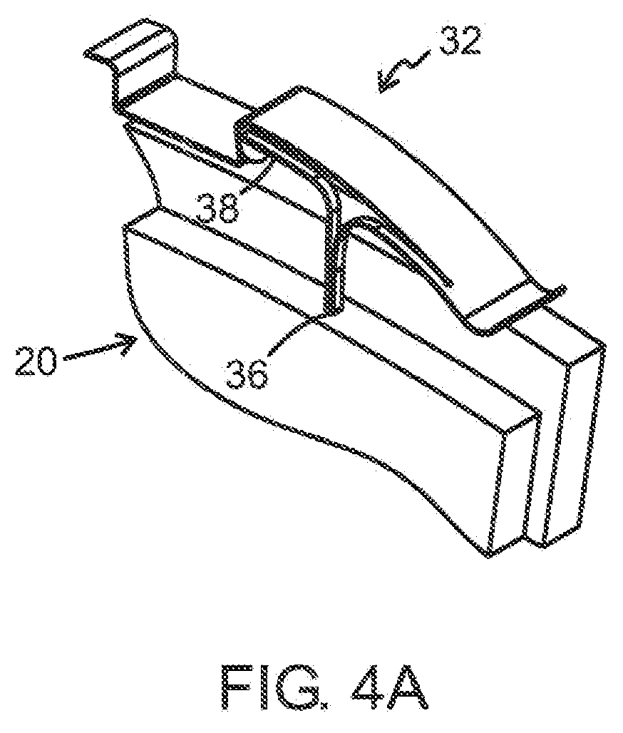
FIGS. 4A-B depict a detail view of a section of a brake lining and a spring according to an embodiment of the invention. They illustrate the indicator function of the spring which inFIG. 4A is in a tensioned state and inFIG. 4B is in an unloaded state. -
FIG. 5 is a schematic general view as seen obliquely from above of a disc brake device according to an embodiment of the invention. -
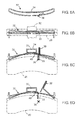
FIGS. 6A-D illustrate an embodiment of a brake lining/indicator/return spring according to the invention.FIG. 6A is a view from above of an unloaded spring;FIG. 6B is a view from above of a spring fitted on a lining carrier above a brake lining;FIG. 6C is a side view of a spring fitted on a brake lining; andFIG. 6D is a side view of the same spring when its sacrificial section has been worn away. -
FIG. 1 depicts an example of an embodiment of a disc brake device according to the invention. Adisc brake device 10 is fitted to, and adapted to braking, awheel shaft 12. Thedisc brake device 10 comprises abrake disc 14 mounted on thewheel shaft 12, and abrake yoke 16 fitted non-rotatably and adapted to gripping with controllable force about thebrake disc 14. - The
brake yoke 16 inFIG. 2 comprises alining carrier 18 on which a first and asecond brake lining yoke saddle 24 which surrounds thebrake linings lining carrier 18. Abrake piston 26 is adapted, upon brake application, to pressing thefirst brake lining 20 against thebrake disc 14, whereupon corresponding reaction forces push theyoke saddle 24 and hence thesecond brake lining 22 with substantially the same force in the other direction, i.e. towards the other side of thebrake disc 14. In the upper portion of theyoke saddle 24 there is an assembly aperture 28 (FIG. 1 ) which makes it possible to change thebrake linings brake yoke 16. Above theassembly aperture 28 there is aremovable lining retainer 30 adapted, with abrake lining spring 32 which is fastened to thelining retainer 30 and takes the form of a leaf spring, to pushing thebrake lining 20 radially towards theshaft 12 and axially away from thedisc 14. A tab (FIGS. 4A-B ) on theleaf spring 32 is adapted to indicating when the wear on thebrake lining 20 reaches a predetermined level. A correspondingleaf spring 31 for the lining 22 is also depicted in the diagram. -
FIG. 3 depicts an example of how abrake lining spring bent portion 35 in the form of an undercut trapezoidal profile allows a releasable connection relative to the lining retainer. Thespring 32 is bent in such a way that it is adapted to pushing a lining 20 both downwards (arrow 1) and axially (arrow 2). The axial force is provided, for example, by the respective arms of the spring being somewhat rotated or by thebent portion 35 giving them a slope relative to the plane of the lining retainer. Thespring 32 is further provided with a curved tab (not depicted inFIG. 3 ), the configuration and function of which are illustrated in more detail inFIGS. 4A-B . -
FIGS. 4A-B are detail views of an embodiment of aspring 32 which comprises a tab with indicator function.FIG. 4A depicts the spring in a tensioned state. A sacrificial portion belonging to thespring 32 is connected to thebrake lining 20 in such a way that when the connection is worn away against thebrake disc 14, thespring 32 will describe a springing movement whereby anindicator element 38 will spring out through theassembly aperture 28 of the brake piston and indicate that thebrake lining 20 has reached a predetermined wear level. The connection may be by adhesive bonding or soldering, a tab on the brake lining being adapted to hooking firmly in a bend in the sacrificial portion of the spring, or some other suitable connection. -
FIG. 5 depicts another example of an embodiment of a disc brake device according to the invention, in which thesprings wire spring respective brake lining retainer 30. -
FIG. 6A is a view from above of an unloadedspring 32 according to the embodiment inFIG. 5 . InFIGS. 6B-D thisspring 32, abrake lining 20 and the liningretainer 30 are raised from theyoke 16 to illustrate more clearly the function of thespring 32 in cooperation with the liningretainer 30 and thelining 20. Thewire spring 32 is curved in a double arc in which the respective end of the arc is adapted to abutting against thebrake lining 20 and to springingly pushing it radially in the direction towards the shaft (the arrows inFIG. 6C ) and axially away from the disc (the arrows in 6B). Thewire spring 32 further has asection 34 adapted to surrounding, and connecting thespring 32 to, the liningretainer 30; asacrificial section 36 adapted to running down through ahole 33 in the wearing material of thebrake lining 20; anindicator section 38 and asection 40 adapted to being tensioned and springingly abutting and pressing up against the liningretainer 30. In the assembled state (FIGS. 6B-C ) thelining retainer 30 will, via thesection 40, hold down theindicator section 38 which would otherwise, owing to the tensioning of the spring, endeavour to move away from the shaft 12 (FIG. 5 ). When thesacrificial section 36 has worn away (FIG. 6D ) against the brake disc 14 (FIG. 5 ), theindicator section 38 springs up and indicates that thebrake lining 20 has reached a predetermined worn-down level. - If the yoke is provided with a cover, the indicator element or indicator section may be adapted to springing up through an indicating hole in the cover, but the indication may be read in many ways, e.g. visually, mechanically, optically or electromechanically. The indication may also be connected to a warning lamp in the vehicle's instrument panel, to the vehicle's computer or by radio to, for example, a service station.
- Other springs and combinations of springs than wire springs and leaf springs may be used for implementing the invention and be covered by the attached claims. For example, a brake lining spring in the form of a leaf spring may be combined with an indicator spring in the form of a leaf, wire or coil spring provided with a sacrificial section and/or an abradable connection to a lining.
- The spring need not necessarily be connected to the lining retainer by surrounding it as illustrated in the diagrams. It may be connected in some other way, e.g. by a fastening device, or be connected to some other part of the yoke. In fact, it is not even necessary that the spring be connected to the yoke; it may instead be fastened to, for example, the brake lining, or be tensioned in the space between the brake lining and some point on the yoke by its own tensioning force. Nor is it necessary that the spring be worn away in order to achieve an indicator function; other embodiments may for example comprise the spring being worn free from a fastening, e.g. from adhesive bonding or soldering, in the wearing material of the brake lining and thereby be afforded the possibility of performing a springing movement. The fastening need not be arranged through a hole in the wearing material, as it may equally well be arranged in a slit or on an edge of the wearing material at a position situated at a suitable distance from the lining plate on which the wearing material is arranged.
- Nor need the lining retainer be configured as illustrated; it may also take other forms, e.g. that of a cover covering the whole of the assembly aperture, and/or be provided with various kinds of means for releasable connection to a brake lining spring/indicator spring/return spring.
- The description set out above is primarily intended to facilitate comprehension and no unnecessary limitations of the invention are to be inferred therefrom. The modifications which will be obvious to one skilled in the art from perusing the description can be implemented without departing from the concept of the invention or the scope of the claims set out below.
Claims (12)
- A disc brake device comprising
a brake disc (14) with two opposite friction surfaces and adapted to being connected to a rotatable shaft (12); and
a brake yoke (16) adapted to being connected to a non-rotatable part of a machine or vehicle and to moving freely from the brake disc (14) and to straddling the latter with two sidepieces forming part of the brake yoke (16) and each having an extent along part of the respective friction surface; said brake yoke (16) being further provided with brake linings (20, 22) and a brake piston (26) which is arranged in a sidepiece and is adapted to controllably pressing the brake lining (20) against the brake disc (14),
said disc brake device being characterised in that it comprises an indicator spring (32) adapted to being tensioned upon the fitting of a brake lining (20), said indicator spring comprising
a sacrificial portion (36) which is connected to the indicator spring, is adapted to being connected to the brake lining (20) and has an extent such that the sacrificial portion (36), by rubbing against the brake disc (14), is worn away or, alternatively, is worn free from a fastening in the wearing material of the brake lining (20), when the wear on the brake lining (20) reaches a predetermined level; and
an indicator element (38) which is connected to the indicator spring (32) and is adapted to performing, under the tensioning force of the indicator spring (32), a springing movement when the sacrificial portion (36) has been worn away or, alternatively, is worn free from a fastening in the wearing material of the brake lining (20), thereby indicating that the wear on the brake lining (20) has reached the predetermined level. - A disc brake device comprising
a brake disc (14) with two opposite friction surfaces and adapted to being connected to a rotatable shaft (12); and
a brake yoke (16) adapted to being connected to a non-rotatable part of a machine or vehicle and to moving freely from the brake disc (14) and to straddling the latter with two sidepieces forming part of the brake yoke (16) and each having an extent along part of the respective friction surface; said brake yoke (16) being further provided with brake linings (20, 22) and a brake piston (26) which is arranged in a sidepiece and is adapted to controllably pressing the brake lining (20) against the brake disc (14),
said disc brake device being characterised in that it comprises a return spring (32) adapted to pulling or pushing the linings (20, 22) apart in the axial direction. - A disc brake device according to claim 1 which also conforms to the attributes of claim 2, in which the return spring and the indicator spring take the form of one and the same spring (32).
- A brake disc device according to any one of claims 1-3, in which the spring (32) is also adapted to pushing a brake lining (20, 22) radially towards the shaft (12).
- A brake disc device according to any one of claims 1-4, in which the spring (32) is a wire spring.
- A brake disc device according to any one of claims 2-5, in which the yoke comprises a lining carrier (18) connected to a fixed point on a vehicle or machine, and a yoke saddle (24) which is supported for linear movement in the axial direction and comprises said lining retainer (30) and brake piston (26); and in which the abutment surface of the spring (32) against the brake lining (20, 22) constitutes a friction surface for the axial movement of the yoke saddle (24) relative to the brake lining (20, 22).
- A brake disc device according to any one of claims 2-6, in which the spring (32) is adapted to having a first and a second abutment surface (34, 35) against the brake lining (20, 22) and has an extent such that the abutment surfaces (34, 35) are adapted to being situated substantially as far from one another as the portion of the edge of the brake lining (20, 22) which faces towards the assembly aperture (28) allows.
- A disc brake device according to claim 7, in which the spring force with which the first abutment surface (34) of the spring (32) presses on the brake lining (20, 22) is substantially independent of the spring force with which the second abutment surface (35) of the spring (32) presses on the brake lining (20,22).
- A spring in the form of a wire spring (32) adapted to being fitted in a brake yoke (16), said spring (32) comprising
a lining retainer section curved to form an arc in which the respective end of the arc is adapted to abutting against a brake lining (20) and to springingly pushing it radially towards a shaft (12) and axially away from a brake disc (14);
a connecting section (34) adapted to connecting the spring (32) to a lining retainer (30) or an assembly aperture cover;
a tensioning section (40) adapted to being tensioned and to springingly abutting and pressing against the lining retainer (30) or the assembly aperture cover;
a sacrificial section (36) adapted to being connected to the wearing material of the brake lining (20) in such a way that the sacrificial section is worn away when the brake lining has reached a predetermined wear level, whereby the tensioning section (40) separates from the rest of the spring (32); and
an indicator section (38) adapted to springing out through an assembly aperture (28) in the brake yoke (16) and/or through a hole in a cover over the assembly aperture (28) when the tensioning section (40) separates from the rest of the spring (32). - A vehicle provided with a disc brake device (10) according to any one of claims 1-8 or a spring (32) according to claim 6.
- Using a disc brake device (10) according to any one of claims 1-8 for braking a rotary motion.
- Using a spring (32) according to claim 9 for indicating that the wear on a brake lining has reached a predetermined level.
Applications Claiming Priority (1)
| Application Number | Priority Date | Filing Date | Title |
|---|---|---|---|
| SE0702220A SE0702220L (en) | 2007-10-04 | 2007-10-04 | Disc brake device, spring and vehicle and use of such disc brake device or spring |
Publications (2)
| Publication Number | Publication Date |
|---|---|
| EP2045482A1 true EP2045482A1 (en) | 2009-04-08 |
| EP2045482B1 EP2045482B1 (en) | 2010-11-24 |
Family
ID=39941902
Family Applications (1)
| Application Number | Title | Priority Date | Filing Date |
|---|---|---|---|
| EP08165826A Not-in-force EP2045482B1 (en) | 2007-10-04 | 2008-10-03 | Disc brake device, spring and vehicle and using such a disc brake device or spring |
Country Status (4)
| Country | Link |
|---|---|
| EP (1) | EP2045482B1 (en) |
| AT (1) | ATE489563T1 (en) |
| DE (1) | DE602008003636D1 (en) |
| SE (1) | SE0702220L (en) |
Cited By (2)
| Publication number | Priority date | Publication date | Assignee | Title |
|---|---|---|---|---|
| JP2015028376A (en) * | 2013-06-28 | 2015-02-12 | 日立オートモティブシステムズ株式会社 | Disc brake |
| DE102018207180A1 (en) * | 2018-05-08 | 2019-11-14 | Shimano Components (Malaysia) Sdn. Bhd. | Disc brake caliper with a wear indicator and biasing member for disc brake caliper with a wear indicator |
Families Citing this family (1)
| Publication number | Priority date | Publication date | Assignee | Title |
|---|---|---|---|---|
| KR101608858B1 (en) * | 2012-05-31 | 2016-04-05 | 상신브레이크주식회사 | Disk Brake For Vehicle With Wear Compensation Structure |
Citations (7)
| Publication number | Priority date | Publication date | Assignee | Title |
|---|---|---|---|---|
| DE3023105A1 (en) * | 1979-06-20 | 1981-01-08 | Tokico Ltd | Disc brake monitoring system - has datum marks on shoe springs and sliding caliper indicating amount of lining wear |
| DE3726232A1 (en) * | 1986-08-19 | 1988-03-03 | Volkswagen Ag | Device for determining the wear of a friction lining, particularly a brake lining |
| EP0326774A1 (en) | 1988-02-05 | 1989-08-09 | Alliedsignal Europe Services Techniques | Disc brake and brake pad therefor |
| EP0536008A1 (en) * | 1991-09-30 | 1993-04-07 | Alliedsignal Europe Services Techniques | Brake lining provided with a wear indicator device and disc brake equipped with such an element |
| EP0737824A1 (en) * | 1995-04-13 | 1996-10-16 | Madison Cycles Plc | Improvements to brake blocks |
| US5687817A (en) | 1995-01-27 | 1997-11-18 | Tokico Ltd. | Disc brake |
| EP1862691A1 (en) * | 2006-05-29 | 2007-12-05 | Akebono Brake Industry Co., Ltd. | Opposed piston type disc brake |
-
2007
- 2007-10-04 SE SE0702220A patent/SE0702220L/en unknown
-
2008
- 2008-10-03 DE DE602008003636T patent/DE602008003636D1/en active Active
- 2008-10-03 EP EP08165826A patent/EP2045482B1/en not_active Not-in-force
- 2008-10-03 AT AT08165826T patent/ATE489563T1/en not_active IP Right Cessation
Patent Citations (7)
| Publication number | Priority date | Publication date | Assignee | Title |
|---|---|---|---|---|
| DE3023105A1 (en) * | 1979-06-20 | 1981-01-08 | Tokico Ltd | Disc brake monitoring system - has datum marks on shoe springs and sliding caliper indicating amount of lining wear |
| DE3726232A1 (en) * | 1986-08-19 | 1988-03-03 | Volkswagen Ag | Device for determining the wear of a friction lining, particularly a brake lining |
| EP0326774A1 (en) | 1988-02-05 | 1989-08-09 | Alliedsignal Europe Services Techniques | Disc brake and brake pad therefor |
| EP0536008A1 (en) * | 1991-09-30 | 1993-04-07 | Alliedsignal Europe Services Techniques | Brake lining provided with a wear indicator device and disc brake equipped with such an element |
| US5687817A (en) | 1995-01-27 | 1997-11-18 | Tokico Ltd. | Disc brake |
| EP0737824A1 (en) * | 1995-04-13 | 1996-10-16 | Madison Cycles Plc | Improvements to brake blocks |
| EP1862691A1 (en) * | 2006-05-29 | 2007-12-05 | Akebono Brake Industry Co., Ltd. | Opposed piston type disc brake |
Cited By (4)
| Publication number | Priority date | Publication date | Assignee | Title |
|---|---|---|---|---|
| JP2015028376A (en) * | 2013-06-28 | 2015-02-12 | 日立オートモティブシステムズ株式会社 | Disc brake |
| DE102018207180A1 (en) * | 2018-05-08 | 2019-11-14 | Shimano Components (Malaysia) Sdn. Bhd. | Disc brake caliper with a wear indicator and biasing member for disc brake caliper with a wear indicator |
| CN110454530A (en) * | 2018-05-08 | 2019-11-15 | 株式会社岛野马来西亚配件厂有限公司 | Disc brake caliper including wear indicator and biasing member for disc brake caliper including wear indicator |
| CN110454530B (en) * | 2018-05-08 | 2021-11-02 | 株式会社岛野马来西亚配件厂有限公司 | Disc brake caliper comprising a wear indicator and biasing member for a disc brake caliper comprising a wear indicator |
Also Published As
| Publication number | Publication date |
|---|---|
| DE602008003636D1 (en) | 2011-01-05 |
| SE531160C2 (en) | 2009-01-07 |
| EP2045482B1 (en) | 2010-11-24 |
| SE0702220L (en) | 2009-01-07 |
| ATE489563T1 (en) | 2010-12-15 |
Similar Documents
| Publication | Publication Date | Title |
|---|---|---|
| RU2490525C2 (en) | Brake pad of disc brake | |
| AU2016235731B2 (en) | Disc brake pad retention system and mounting method | |
| CN104271978B (en) | Disc brakes and brake pads with return device | |
| JP3213191B2 (en) | Disc brake | |
| EP2584213B1 (en) | Mechanical arresting disk brake | |
| EP2584212B1 (en) | Mechanical arresting disk brake | |
| CN101825148A (en) | Disc brakes | |
| EP2045482B1 (en) | Disc brake device, spring and vehicle and using such a disc brake device or spring | |
| KR101238254B1 (en) | Friction element and disc brake | |
| EP1521006A1 (en) | Brake caliper | |
| JPS63115924A (en) | Disc brake pads and disc brakes equipped with the same pads | |
| US10697513B2 (en) | Brake pad wear detector | |
| WO2018117234A1 (en) | Brake pad assembly and caliper | |
| US10550904B2 (en) | Disc brake for a commercial vehicle | |
| JP6140659B2 (en) | Friction pad and brake caliper system | |
| CN115038891B (en) | Vehicle disc brake device, brake pad and vehicle | |
| US7011185B2 (en) | Low cost brake sensor | |
| US4085827A (en) | Disc brake wear indicator | |
| US20250146547A1 (en) | Disc Brake for a Utility Vehicle, and Brake Lining for a Disc Brake | |
| JP2006138475A (en) | Disc brake | |
| US4311214A (en) | Disc brake | |
| KR20020007609A (en) | Pad wear indicator of disc brake | |
| JP6025668B2 (en) | Friction pad and brake caliper system | |
| JP4926121B2 (en) | Disc brake | |
| CN113272571B (en) | Pad-spring assemblies for disc brakes and brake calipers |
Legal Events
| Date | Code | Title | Description |
|---|---|---|---|
| PUAI | Public reference made under article 153(3) epc to a published international application that has entered the european phase |
Free format text: ORIGINAL CODE: 0009012 |
|
| AK | Designated contracting states |
Kind code of ref document: A1 Designated state(s): AT BE BG CH CY CZ DE DK EE ES FI FR GB GR HR HU IE IS IT LI LT LU LV MC MT NL NO PL PT RO SE SI SK TR |
|
| AX | Request for extension of the european patent |
Extension state: AL BA MK RS |
|
| 17P | Request for examination filed |
Effective date: 20091003 |
|
| AKX | Designation fees paid |
Designated state(s): AT BE BG CH CY CZ DE DK EE ES FI FR GB GR HR HU IE IS IT LI LT LU LV MC MT NL NO PL PT RO SE SI SK TR |
|
| 17Q | First examination report despatched |
Effective date: 20091207 |
|
| GRAP | Despatch of communication of intention to grant a patent |
Free format text: ORIGINAL CODE: EPIDOSNIGR1 |
|
| GRAS | Grant fee paid |
Free format text: ORIGINAL CODE: EPIDOSNIGR3 |
|
| GRAA | (expected) grant |
Free format text: ORIGINAL CODE: 0009210 |
|
| AK | Designated contracting states |
Kind code of ref document: B1 Designated state(s): AT BE BG CH CY CZ DE DK EE ES FI FR GB GR HR HU IE IS IT LI LT LU LV MC MT NL NO PL PT RO SE SI SK TR |
|
| REG | Reference to a national code |
Ref country code: GB Ref legal event code: FG4D |
|
| REG | Reference to a national code |
Ref country code: CH Ref legal event code: EP |
|
| REG | Reference to a national code |
Ref country code: IE Ref legal event code: FG4D |
|
| REF | Corresponds to: |
Ref document number: 602008003636 Country of ref document: DE Date of ref document: 20110105 Kind code of ref document: P |
|
| REG | Reference to a national code |
Ref country code: NL Ref legal event code: VDEP Effective date: 20101124 |
|
| LTIE | Lt: invalidation of european patent or patent extension |
Effective date: 20101124 |
|
| PG25 | Lapsed in a contracting state [announced via postgrant information from national office to epo] |
Ref country code: NO Free format text: LAPSE BECAUSE OF FAILURE TO SUBMIT A TRANSLATION OF THE DESCRIPTION OR TO PAY THE FEE WITHIN THE PRESCRIBED TIME-LIMIT Effective date: 20110224 Ref country code: LT Free format text: LAPSE BECAUSE OF FAILURE TO SUBMIT A TRANSLATION OF THE DESCRIPTION OR TO PAY THE FEE WITHIN THE PRESCRIBED TIME-LIMIT Effective date: 20101124 |
|
| PG25 | Lapsed in a contracting state [announced via postgrant information from national office to epo] |
Ref country code: CY Free format text: LAPSE BECAUSE OF FAILURE TO SUBMIT A TRANSLATION OF THE DESCRIPTION OR TO PAY THE FEE WITHIN THE PRESCRIBED TIME-LIMIT Effective date: 20101124 Ref country code: IS Free format text: LAPSE BECAUSE OF FAILURE TO SUBMIT A TRANSLATION OF THE DESCRIPTION OR TO PAY THE FEE WITHIN THE PRESCRIBED TIME-LIMIT Effective date: 20110324 Ref country code: HR Free format text: LAPSE BECAUSE OF FAILURE TO SUBMIT A TRANSLATION OF THE DESCRIPTION OR TO PAY THE FEE WITHIN THE PRESCRIBED TIME-LIMIT Effective date: 20101124 Ref country code: NL Free format text: LAPSE BECAUSE OF FAILURE TO SUBMIT A TRANSLATION OF THE DESCRIPTION OR TO PAY THE FEE WITHIN THE PRESCRIBED TIME-LIMIT Effective date: 20101124 Ref country code: SI Free format text: LAPSE BECAUSE OF FAILURE TO SUBMIT A TRANSLATION OF THE DESCRIPTION OR TO PAY THE FEE WITHIN THE PRESCRIBED TIME-LIMIT Effective date: 20101124 Ref country code: SE Free format text: LAPSE BECAUSE OF FAILURE TO SUBMIT A TRANSLATION OF THE DESCRIPTION OR TO PAY THE FEE WITHIN THE PRESCRIBED TIME-LIMIT Effective date: 20101124 Ref country code: BG Free format text: LAPSE BECAUSE OF FAILURE TO SUBMIT A TRANSLATION OF THE DESCRIPTION OR TO PAY THE FEE WITHIN THE PRESCRIBED TIME-LIMIT Effective date: 20110224 Ref country code: PT Free format text: LAPSE BECAUSE OF FAILURE TO SUBMIT A TRANSLATION OF THE DESCRIPTION OR TO PAY THE FEE WITHIN THE PRESCRIBED TIME-LIMIT Effective date: 20110324 Ref country code: FI Free format text: LAPSE BECAUSE OF FAILURE TO SUBMIT A TRANSLATION OF THE DESCRIPTION OR TO PAY THE FEE WITHIN THE PRESCRIBED TIME-LIMIT Effective date: 20101124 Ref country code: AT Free format text: LAPSE BECAUSE OF FAILURE TO SUBMIT A TRANSLATION OF THE DESCRIPTION OR TO PAY THE FEE WITHIN THE PRESCRIBED TIME-LIMIT Effective date: 20101124 Ref country code: LV Free format text: LAPSE BECAUSE OF FAILURE TO SUBMIT A TRANSLATION OF THE DESCRIPTION OR TO PAY THE FEE WITHIN THE PRESCRIBED TIME-LIMIT Effective date: 20101124 |
|
| PG25 | Lapsed in a contracting state [announced via postgrant information from national office to epo] |
Ref country code: GR Free format text: LAPSE BECAUSE OF FAILURE TO SUBMIT A TRANSLATION OF THE DESCRIPTION OR TO PAY THE FEE WITHIN THE PRESCRIBED TIME-LIMIT Effective date: 20110225 |
|
| PG25 | Lapsed in a contracting state [announced via postgrant information from national office to epo] |
Ref country code: CZ Free format text: LAPSE BECAUSE OF FAILURE TO SUBMIT A TRANSLATION OF THE DESCRIPTION OR TO PAY THE FEE WITHIN THE PRESCRIBED TIME-LIMIT Effective date: 20101124 Ref country code: ES Free format text: LAPSE BECAUSE OF FAILURE TO SUBMIT A TRANSLATION OF THE DESCRIPTION OR TO PAY THE FEE WITHIN THE PRESCRIBED TIME-LIMIT Effective date: 20110307 Ref country code: EE Free format text: LAPSE BECAUSE OF FAILURE TO SUBMIT A TRANSLATION OF THE DESCRIPTION OR TO PAY THE FEE WITHIN THE PRESCRIBED TIME-LIMIT Effective date: 20101124 Ref country code: BE Free format text: LAPSE BECAUSE OF FAILURE TO SUBMIT A TRANSLATION OF THE DESCRIPTION OR TO PAY THE FEE WITHIN THE PRESCRIBED TIME-LIMIT Effective date: 20101124 |
|
| PG25 | Lapsed in a contracting state [announced via postgrant information from national office to epo] |
Ref country code: PL Free format text: LAPSE BECAUSE OF FAILURE TO SUBMIT A TRANSLATION OF THE DESCRIPTION OR TO PAY THE FEE WITHIN THE PRESCRIBED TIME-LIMIT Effective date: 20101124 Ref country code: RO Free format text: LAPSE BECAUSE OF FAILURE TO SUBMIT A TRANSLATION OF THE DESCRIPTION OR TO PAY THE FEE WITHIN THE PRESCRIBED TIME-LIMIT Effective date: 20101124 Ref country code: SK Free format text: LAPSE BECAUSE OF FAILURE TO SUBMIT A TRANSLATION OF THE DESCRIPTION OR TO PAY THE FEE WITHIN THE PRESCRIBED TIME-LIMIT Effective date: 20101124 Ref country code: DK Free format text: LAPSE BECAUSE OF FAILURE TO SUBMIT A TRANSLATION OF THE DESCRIPTION OR TO PAY THE FEE WITHIN THE PRESCRIBED TIME-LIMIT Effective date: 20101124 |
|
| PLBE | No opposition filed within time limit |
Free format text: ORIGINAL CODE: 0009261 |
|
| STAA | Information on the status of an ep patent application or granted ep patent |
Free format text: STATUS: NO OPPOSITION FILED WITHIN TIME LIMIT |
|
| 26N | No opposition filed |
Effective date: 20110825 |
|
| REG | Reference to a national code |
Ref country code: DE Ref legal event code: R097 Ref document number: 602008003636 Country of ref document: DE Effective date: 20110825 |
|
| PG25 | Lapsed in a contracting state [announced via postgrant information from national office to epo] |
Ref country code: IT Free format text: LAPSE BECAUSE OF FAILURE TO SUBMIT A TRANSLATION OF THE DESCRIPTION OR TO PAY THE FEE WITHIN THE PRESCRIBED TIME-LIMIT Effective date: 20101124 |
|
| PG25 | Lapsed in a contracting state [announced via postgrant information from national office to epo] |
Ref country code: MC Free format text: LAPSE BECAUSE OF NON-PAYMENT OF DUE FEES Effective date: 20111031 |
|
| REG | Reference to a national code |
Ref country code: FR Ref legal event code: ST Effective date: 20120629 |
|
| REG | Reference to a national code |
Ref country code: IE Ref legal event code: MM4A |
|
| PG25 | Lapsed in a contracting state [announced via postgrant information from national office to epo] |
Ref country code: FR Free format text: LAPSE BECAUSE OF NON-PAYMENT OF DUE FEES Effective date: 20111102 |
|
| PG25 | Lapsed in a contracting state [announced via postgrant information from national office to epo] |
Ref country code: IE Free format text: LAPSE BECAUSE OF NON-PAYMENT OF DUE FEES Effective date: 20111003 |
|
| PG25 | Lapsed in a contracting state [announced via postgrant information from national office to epo] |
Ref country code: MT Free format text: LAPSE BECAUSE OF FAILURE TO SUBMIT A TRANSLATION OF THE DESCRIPTION OR TO PAY THE FEE WITHIN THE PRESCRIBED TIME-LIMIT Effective date: 20101124 |
|
| PG25 | Lapsed in a contracting state [announced via postgrant information from national office to epo] |
Ref country code: LU Free format text: LAPSE BECAUSE OF NON-PAYMENT OF DUE FEES Effective date: 20111003 |
|
| REG | Reference to a national code |
Ref country code: CH Ref legal event code: PL |
|
| GBPC | Gb: european patent ceased through non-payment of renewal fee |
Effective date: 20121003 |
|
| PG25 | Lapsed in a contracting state [announced via postgrant information from national office to epo] |
Ref country code: GB Free format text: LAPSE BECAUSE OF NON-PAYMENT OF DUE FEES Effective date: 20121003 Ref country code: CH Free format text: LAPSE BECAUSE OF NON-PAYMENT OF DUE FEES Effective date: 20121031 Ref country code: LI Free format text: LAPSE BECAUSE OF NON-PAYMENT OF DUE FEES Effective date: 20121031 |
|
| PG25 | Lapsed in a contracting state [announced via postgrant information from national office to epo] |
Ref country code: TR Free format text: LAPSE BECAUSE OF FAILURE TO SUBMIT A TRANSLATION OF THE DESCRIPTION OR TO PAY THE FEE WITHIN THE PRESCRIBED TIME-LIMIT Effective date: 20101124 |
|
| PG25 | Lapsed in a contracting state [announced via postgrant information from national office to epo] |
Ref country code: HU Free format text: LAPSE BECAUSE OF FAILURE TO SUBMIT A TRANSLATION OF THE DESCRIPTION OR TO PAY THE FEE WITHIN THE PRESCRIBED TIME-LIMIT Effective date: 20101124 |
|
| PGFP | Annual fee paid to national office [announced via postgrant information from national office to epo] |
Ref country code: DE Payment date: 20150929 Year of fee payment: 8 |
|
| REG | Reference to a national code |
Ref country code: DE Ref legal event code: R119 Ref document number: 602008003636 Country of ref document: DE |
|
| PG25 | Lapsed in a contracting state [announced via postgrant information from national office to epo] |
Ref country code: DE Free format text: LAPSE BECAUSE OF NON-PAYMENT OF DUE FEES Effective date: 20170503 |