EP2045119A2 - Driving posture adjusting apparatus - Google Patents
Driving posture adjusting apparatus Download PDFInfo
- Publication number
- EP2045119A2 EP2045119A2 EP08165647A EP08165647A EP2045119A2 EP 2045119 A2 EP2045119 A2 EP 2045119A2 EP 08165647 A EP08165647 A EP 08165647A EP 08165647 A EP08165647 A EP 08165647A EP 2045119 A2 EP2045119 A2 EP 2045119A2
- Authority
- EP
- European Patent Office
- Prior art keywords
- seat
- driver
- seat cushion
- seated
- driver seat
- Prior art date
- Legal status (The legal status is an assumption and is not a legal conclusion. Google has not performed a legal analysis and makes no representation as to the accuracy of the status listed.)
- Withdrawn
Links
- 230000007246 mechanism Effects 0.000 claims abstract description 161
- 230000036544 posture Effects 0.000 description 92
- 238000006073 displacement reaction Methods 0.000 description 25
- 230000008859 change Effects 0.000 description 19
- 238000012937 correction Methods 0.000 description 15
- 230000008901 benefit Effects 0.000 description 14
- 238000010586 diagram Methods 0.000 description 12
- 210000002683 foot Anatomy 0.000 description 12
- 238000012546 transfer Methods 0.000 description 11
- 238000004804 winding Methods 0.000 description 11
- 210000000689 upper leg Anatomy 0.000 description 9
- 238000009434 installation Methods 0.000 description 8
- 230000004044 response Effects 0.000 description 7
- 210000002414 leg Anatomy 0.000 description 6
- 238000003825 pressing Methods 0.000 description 6
- 230000005540 biological transmission Effects 0.000 description 5
- 238000013461 design Methods 0.000 description 4
- 239000012212 insulator Substances 0.000 description 4
- 210000003127 knee Anatomy 0.000 description 4
- 230000000717 retained effect Effects 0.000 description 4
- 238000004088 simulation Methods 0.000 description 4
- 238000000034 method Methods 0.000 description 3
- 230000001681 protective effect Effects 0.000 description 3
- 230000009467 reduction Effects 0.000 description 3
- 238000003466 welding Methods 0.000 description 3
- 229910000831 Steel Inorganic materials 0.000 description 2
- 210000003423 ankle Anatomy 0.000 description 2
- 238000004364 calculation method Methods 0.000 description 2
- 230000006866 deterioration Effects 0.000 description 2
- 239000004973 liquid crystal related substance Substances 0.000 description 2
- 239000000463 material Substances 0.000 description 2
- 239000010959 steel Substances 0.000 description 2
- 230000000007 visual effect Effects 0.000 description 2
- 238000005452 bending Methods 0.000 description 1
- 230000008602 contraction Effects 0.000 description 1
- 238000001514 detection method Methods 0.000 description 1
- 238000011161 development Methods 0.000 description 1
- 230000018109 developmental process Effects 0.000 description 1
- 238000007519 figuring Methods 0.000 description 1
- 239000011491 glass wool Substances 0.000 description 1
- 238000009413 insulation Methods 0.000 description 1
- 230000008569 process Effects 0.000 description 1
- 230000003014 reinforcing effect Effects 0.000 description 1
- 125000006850 spacer group Chemical group 0.000 description 1
- 239000002344 surface layer Substances 0.000 description 1
- 229920003002 synthetic resin Polymers 0.000 description 1
- 239000000057 synthetic resin Substances 0.000 description 1
- 238000012360 testing method Methods 0.000 description 1
Images












Classifications
-
- B—PERFORMING OPERATIONS; TRANSPORTING
- B60—VEHICLES IN GENERAL
- B60N—SEATS SPECIALLY ADAPTED FOR VEHICLES; VEHICLE PASSENGER ACCOMMODATION NOT OTHERWISE PROVIDED FOR
- B60N2/00—Seats specially adapted for vehicles; Arrangement or mounting of seats in vehicles
- B60N2/02—Seats specially adapted for vehicles; Arrangement or mounting of seats in vehicles the seat or part thereof being movable, e.g. adjustable
- B60N2/04—Seats specially adapted for vehicles; Arrangement or mounting of seats in vehicles the seat or part thereof being movable, e.g. adjustable the whole seat being movable
- B60N2/16—Seats specially adapted for vehicles; Arrangement or mounting of seats in vehicles the seat or part thereof being movable, e.g. adjustable the whole seat being movable height-adjustable
- B60N2/1605—Seats specially adapted for vehicles; Arrangement or mounting of seats in vehicles the seat or part thereof being movable, e.g. adjustable the whole seat being movable height-adjustable characterised by the cinematic
- B60N2/161—Rods
- B60N2/1615—Parallelogram-like structure
-
- B—PERFORMING OPERATIONS; TRANSPORTING
- B60—VEHICLES IN GENERAL
- B60N—SEATS SPECIALLY ADAPTED FOR VEHICLES; VEHICLE PASSENGER ACCOMMODATION NOT OTHERWISE PROVIDED FOR
- B60N2/00—Seats specially adapted for vehicles; Arrangement or mounting of seats in vehicles
- B60N2/02—Seats specially adapted for vehicles; Arrangement or mounting of seats in vehicles the seat or part thereof being movable, e.g. adjustable
- B60N2/0224—Non-manual adjustments, e.g. with electrical operation
- B60N2/0244—Non-manual adjustments, e.g. with electrical operation with logic circuits
- B60N2/0252—Non-manual adjustments, e.g. with electrical operation with logic circuits with relations between different adjustments, e.g. height of headrest following longitudinal position of seat
-
- B—PERFORMING OPERATIONS; TRANSPORTING
- B60—VEHICLES IN GENERAL
- B60N—SEATS SPECIALLY ADAPTED FOR VEHICLES; VEHICLE PASSENGER ACCOMMODATION NOT OTHERWISE PROVIDED FOR
- B60N2/00—Seats specially adapted for vehicles; Arrangement or mounting of seats in vehicles
- B60N2/02—Seats specially adapted for vehicles; Arrangement or mounting of seats in vehicles the seat or part thereof being movable, e.g. adjustable
- B60N2/0224—Non-manual adjustments, e.g. with electrical operation
- B60N2/0244—Non-manual adjustments, e.g. with electrical operation with logic circuits
- B60N2/0273—Non-manual adjustments, e.g. with electrical operation with logic circuits taking into account user data, e.g. knee height or physical state
-
- B—PERFORMING OPERATIONS; TRANSPORTING
- B60—VEHICLES IN GENERAL
- B60N—SEATS SPECIALLY ADAPTED FOR VEHICLES; VEHICLE PASSENGER ACCOMMODATION NOT OTHERWISE PROVIDED FOR
- B60N2/00—Seats specially adapted for vehicles; Arrangement or mounting of seats in vehicles
- B60N2/02—Seats specially adapted for vehicles; Arrangement or mounting of seats in vehicles the seat or part thereof being movable, e.g. adjustable
- B60N2/04—Seats specially adapted for vehicles; Arrangement or mounting of seats in vehicles the seat or part thereof being movable, e.g. adjustable the whole seat being movable
- B60N2/06—Seats specially adapted for vehicles; Arrangement or mounting of seats in vehicles the seat or part thereof being movable, e.g. adjustable the whole seat being movable slidable
- B60N2/067—Seats specially adapted for vehicles; Arrangement or mounting of seats in vehicles the seat or part thereof being movable, e.g. adjustable the whole seat being movable slidable by linear actuators, e.g. linear screw mechanisms
-
- B—PERFORMING OPERATIONS; TRANSPORTING
- B60—VEHICLES IN GENERAL
- B60N—SEATS SPECIALLY ADAPTED FOR VEHICLES; VEHICLE PASSENGER ACCOMMODATION NOT OTHERWISE PROVIDED FOR
- B60N2/00—Seats specially adapted for vehicles; Arrangement or mounting of seats in vehicles
- B60N2/02—Seats specially adapted for vehicles; Arrangement or mounting of seats in vehicles the seat or part thereof being movable, e.g. adjustable
- B60N2/04—Seats specially adapted for vehicles; Arrangement or mounting of seats in vehicles the seat or part thereof being movable, e.g. adjustable the whole seat being movable
- B60N2/16—Seats specially adapted for vehicles; Arrangement or mounting of seats in vehicles the seat or part thereof being movable, e.g. adjustable the whole seat being movable height-adjustable
- B60N2/1695—Seats specially adapted for vehicles; Arrangement or mounting of seats in vehicles the seat or part thereof being movable, e.g. adjustable the whole seat being movable height-adjustable with simultaneous height and inclination adjustment
-
- B—PERFORMING OPERATIONS; TRANSPORTING
- B60—VEHICLES IN GENERAL
- B60N—SEATS SPECIALLY ADAPTED FOR VEHICLES; VEHICLE PASSENGER ACCOMMODATION NOT OTHERWISE PROVIDED FOR
- B60N3/00—Arrangements or adaptations of other passenger fittings, not otherwise provided for
- B60N3/06—Arrangements or adaptations of other passenger fittings, not otherwise provided for of footrests
- B60N3/063—Arrangements or adaptations of other passenger fittings, not otherwise provided for of footrests with adjustment systems
Definitions
- the present invention relates to a driving position adjusting apparatus for a vehicle, which is adapted to be capable of adjusting a driving position of a driver seated in a driver seat.
- seated conditions such as seated position and seated posture, of a driver seated in a driver seat of a vehicle have been adjusted to be suitable for driving operations, in such a manner that, before sitting on a driver seat, a driver operates a switch to move the driver seat to a predetermined standard position (e.g., an intermediate position of a movable range in a frontward-rearward (i.e., longitudinal) direction of a vehicle body), and then after sitting on the driver seat, the driver operates various switches to sequentially adjust a longitudinal position of the driver seat, a reclining angle of a seat back of the driver seat, and an upward-downward (i.e., vertical) position of a seat cushion of the driver seat, as shown, for example, in JP 10-512214A .
- a predetermined standard position e.g., an intermediate position of a movable range in a frontward-rearward (i.e., longitudinal) direction of a vehicle body
- the driver operates various switches to sequentially adjust a
- the driver seat can be moved frontwardly relative to the standard position to adjust the longitudinal position of the driver seat in conformity to a body size (e.g., leg length) of the driver so as to allow the driver to properly operate an operation pedal, such as an accelerator pedal, arranged in front of the driver seat. Then, the reclining angle of the seat back can be adjusted to make the driver's seated posture comfortable, and the vertical position of the seat cushion can be adjusted to properly ensure forward visibility.
- a body size e.g., leg length
- the reclining angle of the seat back and the vertical position of the seat cushion are adjusted after the adjustment of the longitudinal position of the driver seat, the seated posture of the driver seated in the driver seat is changed, which is likely to cause a problem about deterioration in controllability for (or accessibility to) the operation pedal, and raise a consequent need for re-adjusting the longitudinal position of the driver seat to ensure the controllability for the operation pedal.
- the re-adjustment of the longitudinal position of the driver seat is likely to cause a problem about deteriorations in seated comfort due to deviation between the seated posture and a proper state and in forward visibility due to deviation between the driver's eye point and a proper line, and raise a consequent need for re-adjusting the reclining angle of the seat back and the vertical position of the seat cushion.
- a driving posture adjusting apparatus for a vehicle which is capable of adjusting a driving posture of a driver seated in a driver seat, in an easy and proper manner.
- the present invention provides a driving posture adjusting apparatus for a vehicle, comprising: a seat-position adjusting mechanism adapted to move a seat cushion of a driver seat in a longitudinal direction of a vehicle body so as to adjust a longitudinal position of the driver seat; a seated-posture adjusting mechanism adapted to adjust a seated posture of a driver seated in the driver seat; a controllability adjusting mechanism adapted to adjust controllability for an operation section to be operated by the driver; a seat slide switch adapted to issue an instruction for actuating the seat-position adjusting mechanism to move the seat cushion of the driver seat in the longitudinal direction; and control unit operable to actuate the seated-posture adjusting mechanism and the controllability adjusting mechanism, in correlation with the longitudinal position of the driver seat adjusted according to an input signal through the seat slide switch, so as to obtain a driving posture corresponding to a predetermined recommended position.
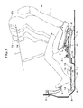
- FIG. 1 shows a driving posture adjusting apparatus for a vehicle, according to a first embodiment of the present invention.
- This driving posture adjusting apparatus comprises a seat-position adjusting mechanism 2 adapted to move a seat cushion 1a of a driver seat 1 in a frontward-rearward (i.e., longitudinal) direction of a vehicle body so as to adjust a longitudinal position of the driver seat 1, a seated-posture adjusting mechanism 3 adapted to adjust a seated posture of a driver seated in the driver seat 1, and a controllability adjusting mechanism comprising a floor lifting/lowering mechanism 7 adapted to selectively drivingly lift and lower a movable floor unit 6 located under feet of the driver seated in the driver seat 1 in such a manner as to cover an upper surface of a floor panel 5 of the vehicle body.
- a seat-position adjusting mechanism 2 adapted to move a seat cushion 1a of a driver seat 1 in a frontward-rearward (i.e., longitudinal) direction of a vehicle body so as to adjust
- the movable floor unit 6 is adapted to allow heels of feet of a driver seated in the driver seat 1 to be placed thereon when the driver presses an operation pedal 4, such as an accelerator pedal or a brake pedal, and the floor lifting/lowering mechanism 7 is adapted to adjust an upward-downward (i.e., vertical) position of the movable floor unit 6 so as to adjust controllability for the operation pedal 4.
- an operation pedal 4 such as an accelerator pedal or a brake pedal
- the floor lifting/lowering mechanism 7 is adapted to adjust an upward-downward (i.e., vertical) position of the movable floor unit 6 so as to adjust controllability for the operation pedal 4.
- the floor panel 5 includes a kick-up portion 9 extending rearwardly and obliquely downwardly from a lower edge of a dash panel 8 separating between an engine compartment and a passenger compartment, and a generally flat floor base portion 10 extending continuously and rearwardly from a rear edge of the kick-up portion 9.
- the floor panel 5 has an upper surface provided with a conventional floor trim material (not shown) which comprises an insulator having sound and heat insulation functions, such as felt insulator or glass wool insulator, and a surface layer made of a carpet material or the like and formed to cover an upper surface of the insulator.
- the floor panel 5 further includes a floor tunnel portion 11 formed in a central region thereof to extend in a longitudinal direction of the vehicle body.
- the floor base portion 10 has a specific zone surrounded by the floor tunnel portion 11, one of a pair of side sills (not shown) each extending in the longitudinal direction along a respective one of opposed longitudinal side edges of the floor panel 5, a cross member 12 extending in a widthwise (i.e., lateral) direction of the vehicle body to support a front end of the driver seat 1, and the kick-up portion 9 of the floor panel 5.
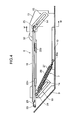
- the floor lifting/lowering mechanism 7 includes a pair of first and second floor support members 13 mounted on respective lateral edges of the specific zone of the floor base portion 10 to support right and left sides of the movable floor unit 6.
- Each of the floor support members 13 has an upstanding wall which extends approximately vertically upwardly from a respective one of the lateral edges of the specific zone of the floor base portion 10, and has front and rear ends formed with respective ones of a pair of front and rear guide grooves 14 extending frontwardly and obliquely upwardly at the same angle, for example, at an angle corresponding to an inclination angle of the kick-up portion 9.
- the upstanding wall of the floor support member 13 has a laterally inner surface mounting thereon a pair of reinforcing plates 15 each formed with a cutout corresponding to a respective one of the front and rear guide grooves 14, and a laterally outer surface mounting thereon a pair of guide members 16 each comprised of a sectionally angular C-shaped channel member having a bottom wall formed with a cutout corresponding to a respective one of the front and rear guide grooves 14.
- Each of the floor support members 13 has a retaining bracket 17a, 17b integrally formed therewith to extend rearwardly from a rear edge thereof and have a configuration capable of being fixed, for example, to an upper surface of the cross member 12.
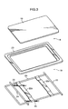
- the movable floor unit 6 comprises a flat plate-shaped board member 18 providing a loading surface for placing thereon heels of a driver seated in the driver seat 1, and a base member 19 for supporting the board member 18 in a liftable and lowerable manner.
- the base member 19 includes a rim segment 20 formed by bending a rod-like member into an angular C shape, front and rear connection segments 22a, 22b each formed of a plate-shaped member connecting opposite lateral sides of the rim segment 20, and an outer frame segment 23 fixedly mounted on the rim segment 20.
- the board member 18 is placed on the outer frame segment 23 and the connection segments 22a, 22b, and fixedly fastened together by screw clamping or other fastening means.
- the rim segment 20 is provided with first and second slide shafts 24, 25.
- the first slide shaft 24 is fixed to lower surfaces of respective front regions of the lateral sides thereof by welding or other fixing means to extend laterally
- the second slide shaft 25 is interconnectingly fixed to respective rear edges thereof by welding or other fixing means to extend laterally.
- Each of the slide shafts 24, 25 is formed and arranged to have opposite lateral ends protruding laterally from the rim member 20, wherein the protruding lateral ends of the first slide shaft 24, and the protruding lateral ends of the second slide shaft 25, are insertedly supported, respectively, by the opposed front guide grooves 14 and the opposed rear guide grooves 14 of the first and second floor support members 13 in a slidable manner.
- the first slide shaft 24 located on a frontward side relative to the second slide shaft 25 is associated with biasing means 26, such as two tension springs.
- the biasing means 26 has a front end attached to each of right and left portions of the first slide shaft 24, and a rear end attached to a vehicle body-side member, such as a retaining protrusion 10a provided on the floor base portion 10.
- the biasing means 26 is adapted to bias the first slide shaft 24 rearwardly and downwardly along the front guide grooves 14.
- the biasing means 26 has a synthetic resin tube member 27 attached thereto to cover an outer periphery thereof so as to suppress generation of noise during stretch and contraction.
- a first one (in the first embodiment, a laterally outward one) of the lateral ends of the second slide shaft 25 located on a rearward side relative to the first slide shaft 24 is associated with a first cable end ring 29, and a second cable end ring 31.
- the first cable end ring 29 is provided at a distal end of a pull cable 28 which is adapted to transmit a driving force to the first end of the second slide shaft 25 in the form of a tension force during an operation of moving the seat cushion 1a of the driver seat 1 by the seat-position adjusting mechanism 2.
- the second cable end ring 31 is provided at a proximal end of a transfer cable 30 adapted to transfer the driving force transmitted from the pull cable 28 to the first end of the second slide shaft 25, to the other, second, end (in the first embodiment, a laterally inward end) of the second slide shaft 25.
- the first and second cable end rings 29, 31 are fixedly fastened to the first end of the second slide shaft 25, through a fastening member 32, such as a flanged screw, and a spacer 33.
- the pull cable 28 includes an outer casing 28a comprised of a flexible tube member, and an inner wire 28b slidably supported by the outer casing 28a
- the transfer cable 30 includes an outer casing 30a comprised of a flexible tube member, and an inner wire 30b slidably supported by the outer casing 30a.
- the inner wire 28b of the pull cable 28 is slidably moved along the outer casing 28a to transmit the driving force to the first end of the second slide shaft 25 via the inner wire 28b.
- the inner wire 30b of the transfer cable 30 is slidingly moved along the outer casing 30a to transfer the driving force to the second end of the second slide shaft 25 via the inner wire 30b.
- the first floor support member 13 located on an laterally outward side relative to the second floor support member 13 has as a retaining portion 34 and a support shaft 35a.
- the retaining portion 34 is provided at a rear upper position of the first floor support member 13, and a distal (front) end of the outer casing 28a of the pull cable 28 is retained by the retaining portion 34.
- the support shaft 35a is provided at an upper position of the first floor support member 13 on a frontward side relative to the rear guide member 16, and a guide pulley 35 for allowing a portion of the inner wire 28b led out of the distal end the outer casing 28a to be wound therearound is rotatably supported by the support shaft 35a.
- the portion of the inner wire 28b of the pull cable 28 is led rearwardly after being wound around the guide pulley 35 from a lower side to an upper side thereof at a winding angle of 180° or more, so that the distal end (first cable end ring 29) is guided downwardly from an upper end of the rear guide member 16.
- the rear guide member 16 has a lower end provided with a retaining portion 36, and a distal end of the outer casing 30a of the transfer cable 30 is retained by the retaining portion 36.
- the second floor support member 13 located on a laterally inward side relative to the first floor support member 13 has a retaining portion 39, and a support shaft 38a.
- the retaining portion 39 is provided at a rear upper position of the second floor support member 13, and a distal end of the outer casing 30a of the transfer cable 30 is retained by the retaining portion 39.
- the support shaft 38a is provided at an upper position of the second floor support member 13 on a frontward side relative to the rear guide member 16, and a guide pulley 38 for allowing a portion of the inner wire 30b led out of the distal end the outer casing 30a to be wound therearound is rotatably supported by the support shaft 38a.
- the portion of the inner wire 30b of the transfer cable 30 is led rearwardly after being wound around the guide pulley 38 from a lower side to an upper side thereof at a winding angle of 180°or more, so that the distal end (second cable end ring 31) is guided downwardly from an upper end of the rear guide member 16.
- Each of the first and second floor support members 13 also has a restriction potion 50 provided between the guide member 16 and the guide pulley (35, 38), and adapted to restrict a height position of the inner wire (28b, 30b) of a respective one of the pull cable 28 and the transfer cable 30, which is guided to the lower side of the guide pulley (35, 38) across the guide member 16, in such a manner as to allow the height position of the inner wire (28b, 30b) to become equal to a height position of the guide pulley (35, 38).
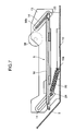
- the movable floor unit 6 in a state when the seat cushion 1a of the driver seat 1 is set in a rearmost position of a slidable range of the driver seat 1, the movable floor unit 6 is held in a lowermost position according to a biasing force of the biasing means 26 biasing the slide shafts 24, 25 downwardly and a weight of the movable floor unit 6, as shown in FIG. 7 .
- a pair of right and left seat slide lower rails 41 are installed on the cross member 12 and a portion of the floor panel 5 located in an installation area of the driver seat 1, in such a manner as to support the seat cushion 1a in a frontwardly-rearwardly movable manner.
- a pair of right and left seat slide upper rails 42 are supported by the respective right and left seat slide lower rails 41 in a slidably displaceable manner.
- Each of the seat slide lower rails 41 is comprised of a C-shaped steel member having an upper opening, and two brackets 43, 44 are integrally joined to respective front and rear ends of the seat slide lower rail 41 by welding or other fixing means.
- the brackets 43, 44 are fixed, respectively, to the upper surface of the cross member 12 and the floor panel 5 by fastening bolts or other fastening means, so that each of the seat slide lower rails 41 is installed on the floor panel 5 with a slight frontwardly upward inclination.
- a rotary shaft 45 comprised of a screw shaft is rotatably installed within each of the right and left slide lower rails 41.
- a driving-force transmission section 49 comprised of a bevel gear mechanism or a worm wheel mechanism is provided at each of right and left ends of the drive shaft 47 to transmit a driving force of the drive shaft 47 to a respective one of the rotary shaft 45.
- the seat-position adjusting mechanism 2 adapted to slidably displace the seat cushion 1a of the driver seat 1 along the seat slide lower rails 41 so as to adjust a longitudinal position of the driver seat 1 is made up of the seat slide lower rails 41, the seat slide upper rails 42, the rotary shafts 45, the drive motor 46, the drive shaft 47, the driving-force transmission sections 49, and two nut blocks 41 a fixed to respective bottom surfaces of the seat slide lower rails 41 and screwed with the respective rotary shafts 45.
- a control signal for rotating the drive motor 46 in a normal direction is output, and the drive motor 46 is rotated in the normal direction in response to the control signal, so that a driving force causing a frontward movement of the seat cushion 1a is transmitted to the drive shaft 47, the driving-force transmission sections 49 and the rotary shafts 45.
- the rotary shafts 45 are drivenly rotated by the driving force input from the respective driving-force transmission sections 49, and threadingly moved frontwardly, while being supported by the respective nut blocks 41a each fixed to a respective one of the bottom surfaces of the seat slide lower rails 41, so that the seat cushion 1a of the driver seat 1 is drivenly moved frontwardly together with the seat slide upper rails 42.
- the seat slide upper rails 42 are provided with the seated-posture adjusting mechanism 3 adapted to selectively displace the seat cushion 1a of the driver seat 1 upwardly and downwardly, and change an inclination angle of the seat cushion 1a and a reclining angle of the seat back 1b, so as to adjust a seated posture of a driver seated in the driver seat 1.
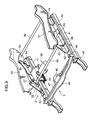
- the seated-posture adjusting mechanism 3 comprises: a pair of right and left cushion frames 51 provided on respective right and left sides of the seat cushion 1a; a pair of right and left front brackets 52 provided on respective upper surfaces of front portions of the right and left seat slide upper rails 42 to support respective front ends of the right and left cushion frames 51 in cooperation with respective ones of a pair of right and left front links 53; a pair of right and left rear brackets 54 provided on respective upper surfaces of rear portions of the right and left seat slide upper rails 42 to support respective rear ends of the right and left cushion frames 51 in cooperation with respective ones of a pair of right and left triangular-shaped rear links 55; a connection shaft 56 connecting respective rear ends of the right and left rear links 55 together and connecting respective rear lower portions of the right and left cushion frames 51 together; a pair of right and left center brackets 58 provided on respective upper surfaces of central portions of the right and left seat slide upper rails 42 to support respective ones of a pair of right and left central links 57 adapted
- Each of the right and left central links 57 is fixed to a laterally-extending drive shaft 60 in a lower end thereof, and rotatably supported by the respective right and left central brackets 58 through the drive shaft 60.
- a drive lever 61 is fixed to the drive shaft 60 to rotatably displace the drive shaft 60.
- a vertical drive section 62 adapted to drivingly move the drive lever 61 fixed to the drive shaft 60 is mounted on the central bracket 58 provided on one (a laterally inward one) of the right and left seat slide upper rails 42.
- the vertical drive section 62 comprises a screw shaft 64 having a front end connected to a distal (lower) end of the drive lever 61 through a connection pin 63, a combination of a drive motor 65 and a gear mechanism 66 which is adapted to drivingly rotate the screw shaft 64, and a guide bracket 67 fixedly attached to a front surface of the gear mechanism 66, wherein a base end of the guide bracket 67 is supported by the central bracket 58 through a support bracket 68.
- the gear mechanism 66 is provided with a worm gear 69 fixedly attached to an output shaft 65a of the drive motor 65, and a worm nut 70 adapted to be drivenly rotated by the worm gear 69, wherein the worm gear 70 is formed with a screw hole screwable with the screw shaft 64.
- each of the front link 53 and the central link 57 is in a rearwardly inclined position, and the connection shaft 56 provided at a rear end of the rear link 55 is in a lowered position, as shown in FIG. 8 .
- a seating surface of the seat cushion 1a is maintained in a lowered position.
- each of the right and left central links 57 is moved to the upstanding position, a driving force of each of the right and left central link 57 is transmitted to the rear link 55 through the connection link 59, and respective front ends of the right and left rear links 55 are pulled frontwardly.
- the connection shaft 56 provided at the rear ends of the right and left rear links 55 is lifted, and therefore the rear end of the seat cushion 1a is drivenly pushed and moved upwardly.
- each of the right and left front links 53 is moved from the rearwardly inclined position to the upstanding position, and therefore the seat cushion 1a is drivenly moved frontwardly while the front end thereof is pushed and moved upwardly.
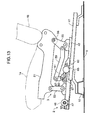
- the seat cushion 1a is displaced from the lowered position to a lifted position, as shown in FIG. 13 .
- a lift amount in the rear end of the seat cushion 1a is set to be greater than that in the front end of the seat cushion 1a, so that, along with the upward movement of the seat cushion 1a, the inclination angle of the seating surface of the seat cushion 1a will gradually decrease, and the reclining angle of the seat back 1b will gradually decrease and get closer to a vertical position.
- one of the seat slide lower rails 41 of the driver seat 1 is provided with a winding mechanism 72 and a fine adjustment mechanism 89.
- the winding mechanism 72 is adapted to reduce a pull stroke of the pull cable 29 to be transmitted to the floor lifting/lowering mechanism 7, during frontward movement of the seat cushion 1a, wherein a rear end of (inner wire 28b) of the pull cable 28 led rearwardly from the installation zone of the floor lifting/lowering mechanism 7 via the cross member 12 is wound around the winding mechanism 72.
- the fine adjustment mechanism 89 is adapted to remove a slack of the pull cable 28 to apply a given tension to the inner wire 28a, and finely adjust the height position of the movable floor unit 6 by a manual operation.
- the winding mechanism 72 comprises a pair of front and rear brackets 73 fixed to the seat slide lower rail 41, a support plate 74 having front and rear ends fixed to the respective front and rear brackets 73 and extending upwardly at a position on a lateral side of the seat slide lower rail 41, a support shaft 75 provided in a rear end of the support plate 74 to protrude therefrom, a large-diameter pulley 76 rotatably supported by the support shaft 75, and a small-diameter pulley 77 connected to the large-diameter pulley 76 in an integrally rotatable manner.
- the support plate 74 has a front end provided with a retaining portion 78 retaining a base (rear) end of the outer casing 28a of the pull cable 28.
- a portion of the inner wire 28b led out rearwardly from the base end of the outer casing 28a retained by the retaining portion 78 is wound around the small-diameter pulley 77, and a T-shaped end clip 28c provided at a base end of the inner wire 28b is engaged with an outer periphery of the small-diameter pulley 77.
- a drive wire 79 is wound around the large-diameter pulley 76, and a T-shaped end clip 79a provided at one end of the drive wire 79 is engaged with an outer periphery of the large-diameter pulley 76.
- the other end of the drive wire 79 is introduced into a guide member 80 comprised of a sectionally C-shaped steel member or the like and attached onto the support plate 74, to extend frontwardly.
- a slide block 81 is provided within the guide member 80, and slidably supported by the guide member 80.
- the slide block 81 is formed with an engagement hole 81a fittable with a drive pin 83 protruding laterally from the central block 58 attached onto the upper surface of the seat slide upper rail 42, and a retaining hole for retaining a T-shaped end clip 79b provided at the other end of the drive wire 79.
- the base end of the pull cable 28 is connected to the seat cushion 1a through the drive wire 79, the drive pin 83, the seat slide upper rail 42 and other associated components.
- the resulting driving force is converted to a force for pulling the inner wire 28b of the pull cable 28, and a pull stroke of the inner wire 28b is transmitted to the floor lifting/lowering mechanism 7 after a pull stroke of the drive wire 79 is reduced by a stroke reduction mechanism comprises of the winding mechanism 72 having the large-diameter pulley 76 and the small-diameter pulley 77.
- the slide block 81 is moved frontwardly along the guide member 80 in conjunction with the frontward movement of the seat cushion 1a, and the other end (T-shaped end clip 79b) is pulled frontwardly to drivingly rotate the large-diameter pulley 76 in a counterclockwise direction (direction indicated by an arrow ⁇ ).
- the small-diameter pulley 77 is rotated by the same angle, so that the pull stroke of the drive wire 79 is reduced by a reduction ratio corresponding to a ratio between respective diameters of the two pulleys 76, 77, and the reduced stroke is transmitted to the inner wire 28b of the pull cable 28.
- a driving force in a direction (direction indicated by an arrow ⁇ ) for pulling out the inner wire 28b from the outer casing 28a of the pull cable 28 rearwardly is generated, and transmitted to a lifting section comprised of the slide shaft 25 of the floor lifting/lowering mechanism 7, so that the slide shafts 24, 25 are slidingly displaced obliquely upwardly along the guide grooves 14 to driven the movable floor unit 6 upwardly.
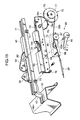
- the fine adjustment mechanism 89 comprises holding means 84 comprised of a ratchet mechanism or the like and provided on an inner wall surface of the support plate 74, an manual operation lever 85 having a drive shaft 85a fittingly attached to the holding means 84, a swing arm 86 detachably attached to the drive shaft 85a of the manual operation lever 85, a dancer pulley 87 supported by a distal end of the swing arm 86, and a protective cover 88 covering an installation area of the swing arm 84 and other associated components.
- the inner wire 28a of the pull cable 28, the manual operation lever 85, the swing arm 86 and other associated components are mounted to the protective cover 88, and this assembly is carried in a passenger compartment together with the seat-position adjusting mechanism 2. Then, after installing the seat-position adjusting mechanism 2 and the floor lifting/lowering mechanism 7, the drive shaft 85a of the manual operation lever 85 is fittingly attached to the holding means 84.
- the T-shaped end clip 28c provided at the base end of the inner wire 28b led rearwardly via the dancer pulley 87 is engaged with the outer periphery of the small-diameter pulley 77, and the protective cover 88 is fixedly fastened to an outer wall surface of the support plate 74 by screw clamping or other fastening means, so that the slide shaft 25 of the floor lifting/lowering mechanism 7 is connected to the seat cushion 1a through the stroke reduction mechanism comprises of the winding mechanism 72 having the large-diameter pulley 76 and the small-diameter pulley 77.
- the manual operation lever 85 is swingingly operated in a direction causing a distal end thereof to be moved downwardly as indicated by the arrow ⁇ in FIGS. 14 and 15 , to swingingly displace the swing arm 86 in a direction causing the dancer pulley 87 to be moved upwardly. Then, the manual operation lever 85 is held at a resulting swing angle by the holding means 84 comprised of a ratchet mechanism or the like.
- the holding means 84 comprised of a ratchet mechanism or the like.
- the slide shaft 25 is lifted along the guide grooves 14, and therefore the movable floor unit 6 is moved obliquely upwardly, so that the height position of the movable floor unit 6 is finely adjusted.
- a holding release lever (not shown) is manually operated to release a holding force of the holding means 84 relative to the swing arm 86.
- the upward force of the dancer pulley 87 relative to the inner wire 28b is released to reduce a tension to be applied to the inner wire 28b.
- the manual operation lever 85 may be swingingly operated in a direction causing the distal end thereof to be moved upwardly, to further reduce a tension to be applied to the inner wire 28b.
- a pull force to be transmitted to the lifting section comprised of the slide shaft of the floor lifting/lowering mechanism 7 is set at zero.
- the slide shaft 24 is lowered along the guide grooves 14 to move the movable floor unit 6 downwardly, so that the height position of the movable floor unit 6 is finely adjusted.
- the driving posture adjusting apparatus further comprises a seat slide switch 91 adapted to issue an instruction for actuating the seat-position adjusting mechanism 2 to move the driver seat 1 in the longitudinal direction; a longitudinal-position adjusting switch 92 adapted to issue an instruction for actuating the seat-position adjusting mechanism 2 to finely adjust the longitudinal position of the driver seat 1; a vertical-position adjusting switch 93 adapted to issue an instruction for actuating the seated-posture adjusting mechanism 3 to selectively displace the seat cushion 1a of the driver seat 1 upwardly and downwardly; a display unit 94 adapted to display a value of body height (i.e., driver's body height) input by manually operating the seat slide switch 91; and a control unit 95 adapted to output a control signal corresponding to a manual operation of each of the switches 91 to 93, to at least each of the seat-position adjusting mechanism 2 and the seated-posture adjusting mechanism 3.
- a seat slide switch 91 adapted to issue an instruction for actuating the seat-position
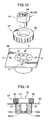
- the seat slide switch 91 comprises: a plurality of first contacts 97 provided on a switch panel 96 and arranged on a circle at certain intervals; a dial-type manual operation member 98 rotatably supported by the switch panel 96; and a second contact 99 provided on a lower surface of the dial-type manual operation member 98.
- the second contact 99 is selectively brought into contact with one of the first contacts 97 in such a manner as that the value of body height to be input is changed in increments of a predetermined reference length, for example, of about 1 to 5 cm, depending on the selected first contact 97, and the value is input into the control unit 95.
- control unit 95 performs a control operation of displaying the input value of body height on the display unit 94 composes of a liquid-crystal display and installed in an upper surface of an after-mentioned lever-type manual operation member 101, and a control operation of adjusting at least the longitudinal position of the driver seat 1 and a height position of the seat cushion 1a, in correlation with the input value of body height.
- the longitudinal-position adjusting switch 92 comprises: a pair of front and rear third contacts 100a, 100b provided in a lower portion of the switch panel 96; a lever-type manual operation member 101 swingably supported by the switch panel 96; and a pair of front and rear fourth contacts 102a, 102b provided on a lower surface of the lever-type manual operation member 101.
- an operator i.e., driver
- swingingly operates the lever-type manual operation member 101 frontwardly i.e., in a direction indicated by an arrow mark A
- an instruction signal instructing to move the driver seat 1 frontwardly is input into the control unit 95.
- the vertical-position adjusting switch 93 comprises a pair of fifth contacts (not shown) provided in the lower portion of the switch panel 96 (and arranged in side-by-side relation to each other in a direction perpendicular to the drawing sheet of FIG. 19 ); and a pair of sixth contacts (not shown) provided on the lower surface of the lever-type manual operation member 101 at positions corresponding to the respective fifth contacts.
- the control unit 95 In response to input of each of the instruction signals from the longitudinal-position adjusting switch 92 and the vertical-position adjusting switch 93, the control unit 95 outputs an actuation command signal to each of the drive motor 46 of the seat-position adjusting mechanism 2 and the drive motor 65 of the seated-posture adjusting mechanism 3, to perform each of a control operation of moving the seat cushion 1a of the driver seat 1 in the longitudinal direction so as to finely adjust the longitudinal position of the driver seat 1, and a control operation of finely adjusting a vertical position and an inclination angle of the seat cushion 1a and a reclining angle of the seat back 1b.
- FIG. 20 is a flowchart showing a control routine to be executed in the control unit 95 in response to the respective manual operations of the switches 91 to 93.
- the seal slide switch 91 Upon start of this control routine, the seal slide switch 91 is placed in an ON state, and it is determined whether the instruction for moving the seat cushion 1a of the driver seat 1 in the longitudinal direction has been issued (Step S1). If the determination is YES, it is determined whether the vehicle is in a running state, based, for example, on an output signal from a wheel speed sensor (not shown) (Step S2).
- Step S3 If the determination in Step S2 is YES, information about error is displayed on the display unit 94 or other display unit (Step S3) to inform an operator of a fact that a driving posture adjusting control operation is in an inhibited state, and then the routine is returned to Step S1.
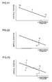
- Step S4 it is determined whether the seat cushion 1a of the driver seat 1 is located on a recommended position line P as shown in FIG. 21 (Step S4).
- This recommended position line P is set based on pre-obtained experimental or simulation data. Specifically, a recommended position for achieving an optimal driving position in conformity to a body size of a driver, such as a longitudinal position of the driver seat 1 and a vertical position of the seat cushion 1a corresponding to the longitudinal position of the driver seat 1, is derived based on pre-obtained experimental or simulation data, and the recommended position line P is set in line with the obtained recommended position.
- a height position and an inclination angle of the seat cushion 1a and a reclining angle of the seat back 1b which allow an eye point (height position of a visual point) I1 of a driver seated in the driver seat 1 to lie on a proper line L while allowing the driver to maintain a comfortable seated posture, and allow an optimal position (ball region) of a sole of the driver to be brought into contact with an operation point 4a (see FIG. 29 etc.) of the operation pedal 4, under conditions that the driver is a tall person T1 having a body height, for example, of about 188 cm, and the driver seat 1 is set in a rearmost position of a movable range in the longitudinal direction as shown in FIG.
- the longitudinal position (rearmost position) of the driver seat 1 and the obtained height position of the seat cushion 1a are plotted on the graph illustrated in FIG. 21 to set a start point P1 of the recommended position line P.
- a height position and an inclination angle of the seat cushion 1a and a reclining angle of the seat back 1b which allow an eye point I4 of a driver seated in the driver seat 1 to lie on the proper line L while allowing the driver to maintain a comfortable seated posture, and allow an optimal position of a sole of the driver to be brought into contact with the operation point 4a of the operation pedal 4, under conditions that the driver is a short person T4 having a body height, for example, of about 150 cm, and the driver seat 1 is set in a frontmost position of the longitudinally movable range as shown in FIG. 1 , are derived based on a standard body size of the short person T4, the design data about driving posture adjusting apparatuses and others. Then, the longitudinal position (frontmost position) of the driver seat 1 and the obtained height position of the seat cushion 1a are plotted on the graph illustrated in FIG. 21 to set an end point P4 of the recommended position line P.
- a distance between the start point and the end point of the recommended position line P is divided equally into a plurality parts, e.g., eight parts, to derive respective longitudinal positions of the driver seat 1 when a body height of a driver to be seated in the driver seat 1 gradually increases in increments of a reference length, for example, of about 5 cm.
- a height position and an inclination angle of the seat cushion 1a and a reclining angle of the seat back 1b which allow an eye point (height of a visual point) of a driver seated in the driver seat 1 to lie on the proper line L while allowing the driver to maintain a comfortable seated posture, and allow an optimal position (ball region) of a sole of the driver to be brought into contact with the operation point 4a of the operation pedal 4, under conditions that the driver is each of a plurality of persons having the respective body heights, and the driver seat 1 is set in each of the longitudinal positions, are derived based on a standard body size of each of the persons, the design data about driving posture adjusting apparatuses and others. Then, a recommended position including the longitudinal positions of the driver seat 1 and the obtained height positions of the seat cushion 1a are plotted on the graph illustrated in FIG. 21 to form a continuous line so as to set the recommended position line P.
- Step S4 determines whether the determination in Step S4 is NO, i.e., it is detected that the seat cushion 1a of the driver seat 1 is not located on the recommended position line P.
- the routine performs a control operation of displacing the height position of the seat cushion 1a to allow it to be returned onto the recommended position line P (Step S5). Specifically, when it is detected that the seat cushion 1a is located at a point R above the recommended position line P or at a point Q below the recommended position line P, as shown in FIG.
- the drive motor 65 of the seated-posture adjusting mechanism 3 is actuated to lift or lower the seat cushion 1a so as to move the seat cushion 1a onto the recommended position line P.
- the seat cushion 1a of the driver seat 1 is moved along the recommended position line P, according to the value of driver's body height input through the seat slide switch 91 (Step S6). For example, if a driver who newly gets into the vehicle inputs his/her body height as 170 cm using the seat slide switch 91 under a condition that another driver has input his/her body height as 175 cm during a previous control operation, the routine performs a control operation of outputting a drive signal for normal rotation to each of the drive motor 46 of the seat-position adjusting mechanism 2 and the drive motor 65 of the seated-posture adjusting mechanism 3, to move the seat cushion 1a of the driver seat 1 frontwardly along the seat slide lower rails 41 while lifting the seat cushion 1a, based on a control value set in conformity to a difference in body height between the two drivers, as indicated by the arrow in FIG. 22 .
- the routine If it is detected, based on an input signal through the seat slide switch 91, that a value of body height of a driver seated in the driver seat 1 is greater than a value of body height of a previous driver, the routine performs a control operation of outputting a drive signal for reverse rotation to each of the drive motor 46 of the seat-position adjusting mechanism 2 and the drive motor 65 of the seated-posture adjusting mechanism 3, to move the seat cushion 1a of the driver seat 1 rearwardly along the seat slide lower rails 41 while lowering the seat cushion 1a, based on a control value set in conformity to a difference in body height between the two drivers.
- the seat cushion 1a is moved along the recommended position line P, and the inclination angle of the seat cushion 1a and the reclining angle of the seat back 1b are adjusted through the seated-posture adjusting mechanism 3, so that the longitudinal position and other positions of the driver seat 1 are adjusted in conformity to the recommended position set based on the pre-obtained experimental or simulation data to achieve a proper posture, and a driving force from the movement of the seat cushion 1a is transferred to the floor lifting/lowering mechanism 7 via the pull cable 28 to drivingly lift/lower the movable floor unit 6 to a proper position capable of ensuring controllability for the control pedal 4.
- the above control operation of moving the seat cushion 1a of the driver seat 1 frontwardly according to a value of driver's body height input through the seat slide switch 91 may be configured as follows. Firstly, it is determined whether the seat cushion 1a is located above or below the recommended position line P. As a result, if it is detected that the seat cushion 1a is located above the recommended position line P as indicated by the point R in FIG. 23 , a control operation is firstly performed such that the drive motor 46 of the seat-position adjusting mechanism 2 is actuated to move the seat cushion 1a of the driver seat 1 frontwardly along the seat slide lower rails 41 by a given distance.
- both the drive motor 46 of the seat-position adjusting mechanism 2 and the drive motor 65 of the seated-posture adjusting mechanism 3 are actuated to move the seat cushion 1a of the driver seat 1 obliquely upwardly along the recommended position line P.
- This configuration makes it possible to the seat cushion to a proper position by the shortest distance.
- the drive motor 65 of the seated-posture adjusting mechanism 3 is actuated to lift the seat cushion 1a to move the seat cushion 1a onto the recommended position line P. Then, both the drive motor 46 of the seat-position adjusting mechanism 2 and the drive motor 65 of the seated-posture adjusting mechanism 3 are actuated to move the seat cushion 1a of the driver seat 1 obliquely upwardly along the recommended position line P.
- the above control operation of moving the seat cushion 1a of the driver seat 1 rearwardly according to a value of driver's body height input through the seat slide switch 91 may be configured as follows. If it is detected that the seat cushion 1a is located below the recommended position line P as indicated by a point V in FIG. 23 , the routine performs a control operation of moving the seat cushion 1a of the driver seat 1 rearwardly along the seat slide lower rails 41 by a given distance, and then at a time when it is detected that the seat cushion 1a is moved onto the recommended position line P, moving the seat cushion 1a of the driver seat 1 obliquely downwardly along the recommended position line P, so as to move the seat cushion to a proper position by the shortest distance.
- the seat cushion 1a of the driver seat 1 is lifted to move the seat cushion 1a onto the recommended position line P, and then moved obliquely downwardly along the recommended position line P.
- Step S7 After moving the seat cushion 1a of the driver seat 1 according to a value of driver's body height input through the seat slide switch 91, in the above manner, it is determined whether an instruction for lifting or lowering the seat cushion 1a is issued based on the manual operation of the vertical-position adjusting switch 93 (Step S7). If the determination is YES, the motor 65 of the seated-posture adjusting mechanism 3 is actuated within a period where the vertical-position adjusting switch 93 is manually kept in an ON state, to lift or lower the seat cushion 1a, depending on the operated direction of the vertical-position adjusting switch 93 so as to finely adjust the vertical position of the seat cushion 1a (Step S8).
- Step S9 it is determined whether an instruction of moving the seat cushion 1a of the driver seat 1 in the longitudinal direction is issued based on the manual operation of the longitudinal-position adjusting switch 92 (Step S9). If the determination is YES, the motor 46 of the seat-position adjusting mechanism 2 is actuated within a period where the longitudinal-position adjusting switch 92 is manually kept in an ON state, to move the seat cushion 1a frontwardly or rearwardly along the seat slide lower rails 41, depending on the operated direction of the longitudinal-position adjusting switch 92 so as to finely adjust the longitudinal position of the seat cushion 1a (Step S10).
- Step S11 it is determined whether a given time has elapsed without the manual operations of the vertical-position adjusting switch 93 and the longitudinal-position adjusting switch 92 (Step S11). If the determination is NO, the routine is returned to Step S9, and the above control operation will be repeated. Then, at a time when the determination in Step S11 becomes YES, i.e., it is detected that the driver seated in the driver seat 1 has stopped the fine adjustment operation of manually operating the vertical-position adjusting switch 93 or the longitudinal-position adjusting switch 92, based on his/her judgment that a driving posture becomes proper, the above control routine is terminated.
- the driving posture adjusting apparatus comprises the seat-position adjusting mechanism 2 adapted to move the seat cushion 1a of the driver seat 1 in a longitudinal direction of a vehicle body so as to adjust a longitudinal position of the driver seat 1, the seated-posture adjusting mechanism 3 adapted to adjust a seated posture of a driver seated in the driver seat 1, and the controllability adjusting mechanism comprised of the floor lifting/lowering mechanism 7 adapted to adjust controllability for the operation pedal 4 to be operated by the driver.
- the driving posture adjusting apparatus further comprises the seat slide switch 91 adapted to issue an instruction for actuating the seat-position adjusting mechanism 2 to move the seat cushion 1a of the driver seat 1 in the longitudinal direction, and the control unit 95 operable to actuate the seated-posture adjusting mechanism 3 and the controllability adjusting mechanism comprised of a floor lifting/lowering mechanism 7, in correlation with the longitudinal position of the driver seat 1 adjusted according to an input signal through the seat slide switch 91, so as to obtain a driving posture corresponding to a predetermined recommended position.
- This provides an advantage of being able to adjust a driving posture of a driver seated on the driver seat 1 in an easy and proper manner.
- a proper seated position and driving posture of a driver seated in the driver seat 1 which allow an eye point of the driver to lie on the proper line L while allowing the driver to be seated in a comfortable posture, and allow a ball region of a sole of the driver to be properly brought into contact with the operation point 4a of the operation pedal 4, also vary depending on a body size of the driver.
- the recommended position line P is set based on data pre-obtained by correlating a driver's body size (body height) with a recommended position comprising the longitudinal position of the driver seat 1, the vertical position and inclination angle of the seat cushion 1a, and the reclining angle of the seat back 1b, which provide a proper seated position and driving posture of each driver.
- the seat-position adjusting mechanism 2 is actuated according to a value of driver's body height input through the seat slide switch 91 to move the seat cushion 1a in the longitudinal direction, and a control signal set based on the longitudinal position of the driver seat 1 and the recommended position line P is output to each of the seated-posture adjusting mechanism 3 and the floor lifting/lowering mechanism 7 to adjust the vertical position of the seat cushion 1a, and others.
- This provides an advantage of being able to adjust a driving posture of a driver in an easy and proper manner on the basis of the predetermined recommended position.
- an eye point of the driver can be adjusted to lie on the proper line L to properly ensure forward visibility, and a ball region of a sole of the driver can be reliably brought into contact with the operation point 4a of the operation pedal 4 so as to properly ensure the controllability for the operation pedal 4, while the driver maintaining a comfortable seated posture.
- the seat cushion 1a of the driver seat 1 is set on the side of the rearmost position of the longitudinally movable range to allow an eye point I1 of the tall person T1 seated in the driver seat 1 to lie on the proper line L, as shown in FIG. 1
- the movable floor unit 6 is set on the side of the lowermost position to allow the tall person T1 to properly perform an operation of pressing the operation pedal 4 arranged in front of the driver seat 1, as shown in FIG. 7 .
- the control unit 95 performs a control operation of actuating the seat-position adjusting mechanism 2 to move the driver seat 1 frontwardly along the recommended position line P, while lifting the seat cushion 1a, so as to allow an eye point I4 of the short person T4 to lie on the proper line L. Further, a driving force based on the movement of the diver seat 1 is transmitted to the lifting section of the floor lifting/lowering mechanism 7, and the movable floor unit 6 is lifted by the floor lifting/lowering mechanism 7.
- the position of the driver seat 1 is automatically adjusted to allow the short person T4 who tends to have short arm and leg lengths as compared with the tall person T1, to properly grip a steering wheel, and the height position of the movable floor unit 6 is automatically adjusted to allow the short person T4 to place his/her foot on the operation pedal 4, such as an accelerator pedal or a brake pedal, and properly press the operation pedal 4.
- the operation pedal 4 such as an accelerator pedal or a brake pedal
- the driving posture adjusting apparatus is provided with the vertical-position adjusting switch 93 adapted to issue an instruction for actuating the drive motor 65 of the seated-posture adjusting mechanism 3 to selectively displace the seat cushion 1a of the driver seat 1 upwardly and downwardly.
- the vertical position of the seat cushion 1a is selectively displaced upwardly and downwardly based on the instruction from the vertical-position adjusting switch 93, so that the vertical position of the seat cushion 1a can be finely adjusted according to driver's preference and physical feature.
- the vertical-position adjusting switch 93 can be operated in a direction for lifting to slightly lift the seat cushion 1a of the driver seat 1 so as to properly ensure forward visibility through a windshield.
- the vertical-position adjusting switch 93 can be operated in a direction for lowering to slightly lower the seat cushion 1a of the driver seat 1, to obtain an advantage of being able to properly ensure the forward visibility.
- the driving posture adjusting apparatus is further provided with the longitudinal-position adjusting switch 92 adapted to issue an instruction for actuating the drive motor 46 of the seat-position adjusting mechanism 2 to finely adjust the longitudinal position of the driver seat 1.
- the seat cushion 1a is slidingly displaced along the seat slide lower rails 41 based on an input signal through the longitudinal-position adjusting switch 92, so that the longitudinal position of the seat cushion 1a can be finely adjusted according to driver's preference and physical feature.
- controllability for the operation pedal 4 is more likely to be improved when the longitudinal position of the driver seat 1 is set at a position on a slightly rearward side relative to a normal position corresponding to the recommended position line P.
- the controllability for the operation pedal 4 can be more effectively improved by operating the longitudinal-position adjusting switch 92 in the direction for rearward movement, to slightly move the driver seat 1 rearwardly.
- the longitudinal-position adjusting switch 92 can be operated in the direction for frontward movement to slightly move the driver seat 1 frontwardly, so as to obtain an advantage of being able to effectively improve the controllability for the operation pedal 4.
- a switch unit such as the switch panel 96 having the seat slide switch 91, the longitudinal-position adjusting switch 92, the vertical-position adjusting switch 93 and the display unit 94, is installed in a location which allows a driver to manually operate each of the switches 91 to 93 without difficulties and accurately recognize a display of the display unit 94, in the passenger compartment.
- the switch unit such as the switch panel 96, may be installed in a location W1 on a console arranged on a lateral side of the driver seat 1. This provides an advantage of being able to manually operate each of the switches 91 to 93 without difficulties, while viewing a display of the display unit 94.
- the switch unit such as the switch panel 96
- the switch unit may be installed in a location W2 on an instrument panel arranged in front of the driver seat 1, or a location W3 on a lateral surface of a side door, or a location W4 on an armrest.
- This provides an advantage of being able to manually operate each of the switches 91 to 93 without difficulties while viewing a display of the display unit 94, and prevent a passenger other than driver from checking the display of the display unit 94 and operating each of the switches 91 to 93.
- FIG. 25 shows a switch unit for use in a driving posture adjusting apparatus according to a second embodiment of the present invention.
- This switch unit comprises a reset switch 103 adapted to issue an instruction for resuming the control operation of adjusting the driving posture based on the recommended position, after completion of the fine adjustment operations based on the input signals through the longitudinal-position adjusting switch 92 and the vertical-position adjusting switch 93.
- the driving posture adjusting apparatus for example, when it becomes unable to determine a direction for adjusting the seat cushion 1a of the driver seat 1, due to a large deviation between the seat cushion 1a of the driver seat 1 and the recommended position line P, caused by the control operation of finely adjusting the vertical position of the seat cushion 1a of the driver seat 1 according to the input signal through vertical-position adjusting switch 93, and the control operation of finely adjusting the longitudinal position of the driver seat 1 according to the input signal through the longitudinal-position adjusting switch 92, or when or a driver is changed to another driver under a condition that the seat cushion 1a of the driver seat 1 is largely deviated from the recommended position line P, the reset switch 193 is manually operated to return the seat cushion 1a of the driver seat 1 onto the recommended position line P. This makes it possible to facilitate shifting to the control operation of adjusting the vertical position and the longitudinal position of the seat cushion 1a based on the recommended position line P.
- the first embodiment has been described based on one example of a control operation configured such that the seated-posture adjusting mechanism 3 is actuated in response to the vertical-position adjusting switch 93 to finely adjust the vertical position and inclination angle of the seat cushion 1a and the reclining angle of the seat back 1b concurrently.
- the control operation may be configured such that three adjusting mechanisms are provided to finely adjust respective ones of the vertical position of the seat cushion 1a, the inclination angle of the seat cushion 1a and the reclining angle of the seat back 1b, according to the respective operations of three adjusting switches each adapted to issue an instruction for a respective ones of the fine adjustments thereof.
- FIG. 26 shows a switch unit for use in a driving posture adjusting apparatus according to a third embodiment of the present invention.
- the switch unit comprises a seat slide switch 91 comprised of a dial-type switch and adapted to allow a value of driver's body height to be input therethrough, a seat cushion switch 105 disposed on a lower (in FIG. 26 ) side relative to the seat slide switch 91, and an reclining-angle adjusting switch 106 disposed on a lateral (in FIG. 26 ) side of the seat slide switch 91.
- the seat cushion switch 105 is comprised of a toggle switch or the like and adapted to issue an instruction for selectively moving the seat cushion 1a of the driver seat 1 frontwardly and rearwardly and selectively displacing the seat cushion 1a of the driver seat 1 upwardly and downwardly.
- the reclining-angle adjusting switch 106 is comprised of a toggle switch or the like and adapted to issue an instruction for finely adjusting a reclining angle of the seat back 1b.
- the seat back 1b may be displaced in a reclining manner by actuating a seated-posture adjusting mechanism which is comprised of a reclining-angle adjusting mechanism adapted to finely adjust the reclining angle of the seat back 1b separately, according to an instruction signal input through the reclining-angle adjusting switch 106.
- a seated-posture adjusting mechanism which is comprised of a reclining-angle adjusting mechanism adapted to finely adjust the reclining angle of the seat back 1b separately, according to an instruction signal input through the reclining-angle adjusting switch 106.
- FIG. 27 shows a switch unit for use in a driving posture adjusting apparatus according to a fourth embodiment of the present invention.
- the switch unit in the fourth embodiment comprises a longitudinal-position adjusting switch 107 comprised of a toggle switch, a slide switch or the like, and adapted to issue an instruction for actuating the aforementioned seat-position adjusting mechanism 2 to selectively move the seat cushion frontwardly and rearwardly, and a vertical-position adjusting switch 108 adapted to issue an instruction for selectively displace the seat cushion 1a of the driver seat 1 upwardly and downwardly.
- the longitudinal-position adjusting switch 107 also serves as a body-height input switch adapted to allow a value of body height to be input therethrough, and display unit 109 comprised of a liquid-crystal display or the like is provided on the longitudinal-position adjusting switch 107.
- the longitudinal-position adjusting switch 107 when the longitudinal-position adjusting switch 107 is manually operated in a direction for frontward or rearward movement, an input value of body height displayed on the display unit 109 is changed. Then, a control operation of moving the driver seat 1 is performed based on the changed input value of body height, and the aforementioned recommended position line P. After this control operation, the vertical position of the seat cushion 1a can be finely adjusted by manually operating the vertical-position adjusting switch 108. Further, the longitudinal position of the driver seat 1 can be finely adjusted by manually operating the longitudinal-position adjusting switch 107 in the direction for frontward or rearward movement.
- the display unit 94, 109 adapted to display a value of body height input through the seat slide switch 91 or the longitudinal-position adjusting switch 107 makes it possible to allow a passenger to readily recognize that the vehicle has a function of automatically adjusting the longitudinal position etc., of the driver seat 1 according to the input signal through the seat slide switch 91 etc., and change an input value of body height based on a content of display on the display unit 94, 109 in an easy and proper manner.
- the display unit 94 or 109 may be disposed in a location different from the installation area of the seat slide switch 91 or the longitudinal-position adjusting switch 107, in the passenger compartment.
- the display unit 94 or 109 is preferably designed to, in response to input of a value of driver's body height through manual operation of the seat slide switch 91 or the longitudinal-position adjusting switch 107, light up or blink a display of the input value of deriver's body height to inform the operator of a fact that the longitudinal position etc., of the driver seat 1 is automatically adjusted according to an input signal of the seat slide switch 91 or the longitudinal-position adjusting switch 107.
- the vehicle is a running state
- information about error is displayer on the display unit 94 (see Step S3 in FIG. 20 ) to inform the operator of a fact that a driving posture adjusting control operation is in an inhibited state, and then the routine is returned, so that the control operation of adjusting the position of the driver seat 1 according to the manual operation of the seat slide switch 91 is inhibited.
- a longitudinally movable distance of the driver seat 1 may be limited to 5 cm or less during running of the vehicle to suppress occurrence of passenger's discomfort.
- a hold switch adapted to inhibit a manual operation of the seat slide switch 91 may be provided in such a manner that the control operation of adjusting the longitudinal position etc., of the driver seat 1 according to the manual operation of the seat slide switch 91 is disenabled, unless an inhibited state of the hold switch is released, so as to effectively suppress occurrence of an undesirable situation where the seat slide switch 91 is erroneously operated during running of the vehicle to cause an accidental longitudinal movement of the driver seat 1.
- display unit may be provided to display a current position of the driver seat.
- information about a position of the seat cushion 1a of the driver seat 1 relative to the recommended position line P may be display on a display unit of a navigation apparatus mounted to the instrument panel of the vehicle. This makes it possible to allow a passenger to readily recognize that that the vehicle has a function of automatically adjusting the longitudinal position etc., of the driver seat 1 in association with an input operation of the seat slide switch 91 etc., and readily and properly perform the control operation of automatically adjusting the longitudinal position etc., of the driver seat 1 while accurately figuring out a current position of the seat cushion 1a based on the displayed information.
- information about a procedure of the following required operations may be displayed on display unit comprised of the display unit of the navigation apparatus to allow a driver to readily recognize an operational procedure for the switches 91 to 93, etc.
- the vertical position of the movable floor unit 6 may be adjusted mechanically independently, in such a manner that a drive motor for lifting/lowering the movable floor unit 6 is provided in the floor lifting/lowering mechanism 7, and controlled by an output signal from the control unit 95, as in the following driving posture adjusting apparatus according to a fifth embodiment of the present invention.
- the longitudinal position of the driver seat 1, and the vertical position and inclination angle of the seat cushion 1a are set up in correlation with a value of driver's body height input from the seat slide switch 91 (or the longitudinal-position adjusting switch 107), in the same manner as that in the first embodiment.
- the control unit 95 sets up the vertical position of the movable floor unit 6, and outputs a control signal corresponding to the setup vertical position of the movable floor unit 6 to the floor lifting/lowering mechanism 7 to automatically adjust the vertical position of the movable floor unit 6 based on an input value of body height.
- a floor adjusting switch adapted to issue an instruction for actuating the drive motor of the floor lifting/lowering mechanism 7 is provided.
- the vertical position of the movable floor unit 6 may be adjusted mechanically independently.
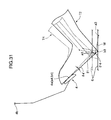
- the seat-position adjusting mechanism 2 is designed such that, when the seat cushion 1a of the driver seat 1 having a longitudinally movable range of 210 mm as shown in FIG. 28 is set at an approximately center of the longitudinally movable range (i.e., intermediate position), and an average-height person T2 having an average body size, such as a body height of about 168 cm, is seated in the driver seat in a proper posture, as indicated by the solid line in FIG. 29 , an eye point I2 of the average-height person T2 lies on the proper line L.
- a drive characteristic of the seat cushion 1a are set such that the seat cushion 1a is moved frontwardly from the intermediate position of the longitudinally movable range by about 105 mm, and simultaneously moved upwardly by about 25 mm, so as to allow a short person T4 having a body height of about 150 cm to be seated in the same posture (proper posture) as that of the average-height person T2, as indicated by the two-dot chain line in FIG. 29 .
- an eye point I4 a waist a2 and a heel a3 of the short person T4 seated in the seat cushion 1a in the proper posture are moved in parallel to each other, as indicated by the arrow M in FIG. 29 , to have a lift amount of 25 mm, and a ball region a4 of a sole of the short person T4 is moved to a position causing contact with the operation point 4a of the operation pedal 4.
- a "proper posture" of a passenger seated in the driver seat 1 means a seated posture capable of maintaining a conformable state for a long period of time and suitable for a pedal operation.
- an ankle angle ⁇ 1 is 90°
- a knee angle ⁇ 2 is 125°
- a bent angle ⁇ 5 between a thigh region and an upper body extending from a sidebone to a shoulder is about 95°.
- an optimal thigh angle ⁇ 3 between a thigh region and a horizontal line is a sum of an inclination angle ⁇ of the seat cushion 1a and about 1.5°.
- a movement locus of the ball region a4 according to the longitudinal movement and upward/downward movement of the seat cushion 1a can be derived based on a joint angle, lengths of a thigh region and a below knee region, etc., of each passenger in the proper posture, by calculation or simulation.
- a movement characteristic of the seat cushion 1a is set such that the seat cushion 1a is moved frontwardly from the approximately intermediate position of the longitudinally movable range by about 105 mm, and simultaneously moved upwardly by about 25 mm, respective ball regions a4, b4 of the short person T4 and the average-height person T2 can be brought into contact with the operation point 4a of the operation pedal 4 while maintaining their seated postures in the proper posture.
- the lift amount (25 mm) of the seat cushion 1a is less than an average of eye-point differences between the average-height person T2 and the short person T4, i.e., an average (about 90 mm) of vertical differences between the eye point I2 and the I4, which is equivalent to a difference in seated height.
- the eye point I4 of the short person T4 will be located below the proper line L, unless a seating-surface angle of the seat cushion 1a, i.e., the inclination angle ⁇ of the seat cushion 1a relative to a horizontal line, is changed to rotate an upper body of the short person T4.
- the eye point of the short person T4 is moved upwardly to lie on the proper line L without changing a contact point of the sole with respect to the operation pedal 4.
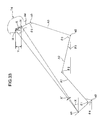
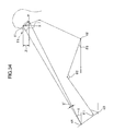
- an upward displacement Y of the eye point I4 caused by the rotation of the upper body of the short person T4 is calculated by multiplying a distance (in an example illustrated in FIG. 33 , about 1040 mm) between the ball region a4 in contact with the operation point 4a of the operation pedal 4 and the eye point I4, by sin X' ⁇ cos X, wherein X is an inclination angle (about 34°) of a segment connecting between the ball region a4 and the eye point I4, relative to a horizontal line, and X' is an amount of change in the inclination angle X caused by the rotation of the upper body of the short person T4, i.e., a value (3°) corresponding to a change in angle of the seat cushion 1a.
- the upward displacement Y of the eye point I4 caused by the rotation of the upper body of the short person T4 is specifically calculated as about 45 mm.
- a sum of upward displacements of the eye point I4 obtained by adding this value, a lowering amount (about 20 mm) of the eye point I4 caused by the frontward movement of the driver seat 1 and a frontwardly downward inclination of the proper line L, and the lift amount (25 cm) of the seat cushion 1a, is a value (about 90 mm) approximately corresponding to the average of eye-point differences between the average-height person T2 and the short person T4.
- the seat cushion 1a is lifted as moving the seat cushion 1a frontwardly, while rotating the upper body of the short person T4, so that the eye point I4 of the short person T4 can be moved to lie on the proper line L while allowing the ball region a4 to be in contact with the operation point 4a of the operation pedal 4.
- the upper body of the short person T4 is rotated together with the seat cushion 1a.
- the upper body of the short person T4 cannot be rotated about the operation point 4a of the operation pedal 4 or the like only by the swing displacement of the seat cushion 1a.
- a movement characteristic of the seat cushion 1a is set such that, when a tall person T1 having a body length of about 188 cm is seated in the driver seat 1 in a proper posture, the seat cushion 1a is moved rearwardly from the intermediate position of the longitudinally movable range by about 105 mm, and simultaneously the seat cushion is moved downwardly by about 25 mm, an eye point I1, a waist c2 and a heel c3 of the tall person T1 seated in the seat cushion 1a in the proper posture are moved in parallel to each other, as indicated by the arrow N in FIG. 30 , to have a lowering amount of 25 mm, and a ball region c4 of the short person T4 is moved to a position causing contact with the operation point 4a of the operation pedal 4.
- the lowering amount (25 mm) of the seat cushion 1a, the eye point I1 and the waist c2 is less than an average of eye-point differences (100 mm) between the average-height person T2 and the tall person T1.
- an average of eye-point differences (100 mm) between the average-height person T2 and the tall person T1 is less than an average of eye-point differences (100 mm) between the average-height person T2 and the tall person T1.
- the rear end of the seat cushion 1a is lowered by the seated-posture adjusting mechanism 3, as moving the seat cushion 1a rearwardly from the intermediate position by about 105 mm, so that the inclination angle of the seat cushion 1a is changed, for example, from 18 to 21° to rotate the upper body of the tall person T1 about the operation point 4a of the operation pedal 4 or the like in such a manner as to be rearwardly inclined.
- the eye point of the tall person T1 is moved downwardly to lie on the proper line L.
- a downward displacement Z of the eye point I1 caused by the rotation of the upper body of the tall person T1 is calculated by multiplying a distance between the ball region c4 in contact with the operation point 4a of the operation pedal 4 and the eye point I1, by tan X' ⁇ cos X, wherein X is an inclination angle (about 34°) of a segment connecting between the ball region c4 and the eye point I1, relative to a horizontal line, and X' is an amount (3°) of change in the inclination angle X caused by the rotation of the upper body of the tall person T1.
- the distance between the ball region c4 and the eye point I1 is specifically calculated as about 1300 mm, and the downward displacement Z of the eye point I1 caused by the rotation of the upper body of the tall person T1 is specifically calculated as about 56 mm.
- a sum (about 101 mm) of downward displacements of the eye point I1 obtained by adding this value, an lift amount (about 20 mm) of the eye point I1 caused by the rearward movement of the driver seat 1 and a frontwardly downward inclination of the proper line L, and the lowering amount (25 cm) of the seat cushion 1a, is approximately equal to a value (about 100 mm) approximately corresponding to the average of eye-point differences between the average-height person T2 and the tall person T1.
- the seat cushion 1a is lowered as moving the seat cushion 1a rearwardly, while rotating the upper body of the tall person T1, so that the eye point I1 of the tall person T1 can be moved to lie on the proper line L while allowing the ball region c4 to be in contact with the operation point 4a of the operation pedal 4.
- the operation of lifting the movable floor unit 6 by the floor lifting/lowering mechanism 7 is configured to be performed based on a drive characteristic set by a lift amount of the seat cushion 1a corresponding to the frontward movement of the driver seat 1, and a lifting/lowering correction value corresponding to a change in the inclination of the seat cushion 1a.
- the seat cushion 1a is moved frontwardly from the intermediate position of the longitudinally movable range by about 105 mm, while lifting the seat cushion 1a by about 25 mm.
- the heel a3 of the short person T4 is moved in parallel to the seat cushion 1a, as indicated by the arrow M in FIG. 31 .
- an inclination angle ⁇ 4 of the sole of the short person T4 relative to a horizontal line is changed from 51.5° to 48.5°, and correspondingly the heel a3 of the short parson T4 is moved further upwardly.
- an upward displacement of the heel a3 can be derived based on a drive characteristic obtained by adding a lift amount of the seat cushion 1a, and a lifting/lowering correction value corresponding to a change in the inclination of the seat cushion 1a.
- An upward displacement (lifting/lowering correction value) of the heel a3 caused by a change in the sole inclination angle ⁇ 4 is calculated by mortifying a pressing height of the operation pedal 4, i.e., a distance between the heel a3 and the ball region a4, by sin ( ⁇ 4'). cos ( ⁇ 4), wherein ⁇ 4' is an amount of change in the sole inclination angle ⁇ 4 corresponding to a change in the inclination angle of the seat cushion 1a.
- the sole inclination angle ⁇ 4 is set at 51.5°, given that a sole size of the short person T4 is 230 mm, and the distance between the heel and the ball region a4 is 45 mm, the pressing height of the operation pedal 4 is about 185 mm, and the amount ⁇ 4' of change in the sole inclination angle ⁇ 4 is 3°.
- a lifting/lowering correction value for the short person T4 is about 9 mm.
- the heel a3 of the short person T4 in a state before movement of the seat cushion 1a should be located at a position slightly below the heel b3 of the average-height person T2 seated in the driver seat 1
- a difference therebetween is significantly small, it is ignored and it is assumed that the heels a3, b3 are the same in height position.
- the drive characteristic representing a vertical displacement of the movable floor unit 6 by the floor lifting/lowering mechanism 7 can be set based on the lift amount of the seat cushion 1a when the seat cushion 1a is moved frontwardly from the intermediate position of the longitudinally movable range by 105 mm, and the lifting/lowering correction value corresponding to the sole inclination angle ⁇ 4 to be changed in conjunction with the operation of changing the inclination angle of the seat cushion 1a from 18° to 15°.
- the driving posture adjusting apparatus is designed to allow the movable floor unit 6 to be driven by the floor lifting/lowering mechanism 7, based on the drive characteristic of the movable floor unit 6.
- an upward displacement of the movable floor unit 6 is a sum of an upward displacement thereof corresponding to a frontward movement of the seat cushion 1a, and the lifting/lowering correction value. That is, the upward displacement of the movable floor unit 6 is maintained in a value greater than the upward displacement of the movable floor unit 6 corresponding to the frontward movement of the seat cushion 1a.
- the drive characteristic of the movable floor unit 6 is configured to allow a vertical distance between the seat cushion 1a and the movable floor unit 6 located below the seat cushion 1a to be reduced along with a frontward movement of the driver seat 1.
- the lifting/lowering correction value represents an amount of change in the vertical distance between the seat cushion 1a and the movable floor unit 6, which is changed along with the frontward movement of the driver seat 1.
- This lifting/lowering correction value is set to be linearly changed along with the frontward movement of the driver seat 1.
- a downward displacement of the heel c3 can be derived based on a lowering amount of the heel c3 corresponding to the downward movement of the seat cushion 1a, and a lifting/lowering correction value corresponding to a change in the inclination of the seat cushion 1a.
- a downward displacement (lifting/lowering correction value) of the heel c3 caused by a change in the sole inclination angle ⁇ 4 is calculated by mortifying a pressing height of the operation pedal 4, i.e., a distance between the heel c3 and the ball region c4 of the sole in contact with the operation point 4a, by sin ( ⁇ 4') ⁇ cos ( ⁇ 4).
- a pressing height of the operation pedal 4 i.e., a distance between the heel c3 and the ball region c4 of the sole in contact with the operation point 4a
- a lifting/lowering correction value for the tall person T1 is about - 11 mm.
- a drive characteristic of the movable floor unit 6 can be derived by adding the lowering amount of the seat cushion 1a when the seat cushion 1a is moved rearwardly from the intermediate position of the longitudinally movable range by 105 mm, and the lifting/lowering correction value corresponding to the sole inclination angle ⁇ 4 to be changed in conjunction with the operation of changing the inclination angle of the seat cushion 1a from 18° to 21°, and a difference between the heels b3, c3.
- the driving posture adjusting apparatus is designed to allow the movable floor unit 6 to be divined by the floor lifting/lowering mechanism 7, based on the drive characteristic of the movable floor unit 6.
- a downward displacement of the movable floor unit 6 is a sum of a downward displacement thereof corresponding to a rearward movement of the seat cushion 1a, and the lifting/lowering correction value. That is, the downward displacement of the movable floor unit 6 is maintained in a value greater than the downward displacement of the movable floor unit 6 corresponding to the rearward movement of the seat cushion 1a.
- the drive characteristic of the movable floor unit 6 is configured to allow a vertical distance between the seat cushion 1a and the movable floor unit 6 located below the seat cushion 1a to be increased along with a rearward movement of the driver seat 1.
- the lifting/lowering correction value represents an amount of change in the vertical distance between the seat cushion 1a and the movable floor unit 6, which is changed along with the rearward movement of the driver seat 1.
- This lifting/lowering correction value is set to be linearly changed along with the rearward movement of the driver seat 1.
- the driver seat 1 is moved in the longitudinal direction according to an input signal of the seat slide switch 91, and the vertical position and inclination angle of the seat cushion 1a are adjusted in correlation with the longitudinal position of the driver seat.
- the vertical position of the movable floor unit 6 is set up based on the vertical position and inclination angle of the seat cushion 1a, and a control signal corresponding to the setup value is output from the control unit 95 to the drive motor of the floor lifting/lowering mechanism 7 and others to selectively displace the movable floor unit 6 upwardly and downwardly.
- the driving posture adjusting apparatus of the present invention may have a controllability adjusting mechanism designed to provide enhanced operational controllability relative to a steering wheel or shift lever to be operated by a driver.
- the present invention provides a driving posture adjusting apparatus for a vehicle, including: a seat-position adjusting mechanism adapted to move a seat cushion of a driver seat in a longitudinal direction of a vehicle body so as to adjust a longitudinal position of the driver seat; a seated-posture adjusting mechanism adapted to adjust a seated posture of a driver seated in the driver seat; and a controllability adjusting mechanism adapted to adjust controllability for an operation section to be operated by the driver.
- the driving-posture adjusting apparatus is characterized by comprising: a seat slide switch adapted to issue an instruction for actuating the seat-position adjusting mechanism to move the seat cushion of the driver seat in the longitudinal direction; and control unit operable to actuate the seated-posture adjusting mechanism and the controllability adjusting mechanism, in correlation with the longitudinal position of the driver seat adjusted according to an input signal through the seat slide switch, so as to obtain a driving posture corresponding to a predetermined recommended position.
- the seat cushion of the driver seat is moved in the longitudinal direction by the seat-position adjusting mechanism according to an input signal through the seat slide switch, and a control signal based on a longitudinal position of the driver seat and the predetermined recommended position is output to the seated-posture adjusting mechanism and the controllability adjusting mechanism to adjust a vertical position of the seat cushion, and others.
- an eye point of the driver can be adjusted to lie on a proper line to properly ensure forward visibility, and a ball region of a sole can be reliably brought into contact with an operation point of the operation section, such as an operation pedal, to properly ensure operational controllability relative to the operation section, while allowing the driver to be seated in the driver seat in a comfortable posture.
- an operation point of the operation section such as an operation pedal
- drivers having different body heights and arm/leg lengths try to adjust a longitudinal position of a driver seat, vertical position of a seat cushion, a reclining angle of a seat back, a height of a floor under the driver's feet and others, individually, to grip a steering wheel in a proper state, and obtain a comfortable joint angle during pressing an operation pedal and adequate eye point.
- automobile manufactures would take steps of setting a recommended posture for each driver's body size, and figure out an adjustment value optimal to the recommended posture on mechanism-by-mechanism in order to design each of the above adjusting mechanism (adjustment range).
- the inventor of this application conceived an idea of providing an apparatus capable of actuating a plurality of adjusting mechanism using a single switch to automatically achieve driving postures recommended for respective drivers.
- the present invention employs a seat slide switch strongly associated with body size as a major factor in estimating body size of each driver to determine the posture and adapted to allow drivers to be intuitively operated and control a longitudinal position of a driver seat.
- the seat slide switch is adapted to allow a value of the driver's body height to be input therethrough as the input signal so as to cause the seat cushion of the driver seat to be moved in the longitudinal direction according to the input value of driver's body height
- the driving posture adjusting apparatus further comprises display unit provided in or in a vicinity of the seat slide switch to display the input value of body height.
- a control signal set based on an input value of body height is output to the seat-position adjusting mechanism and the seated-posture adjusting mechanism to adjust a position of the driver seat.
- a driving posture of the driver can be adjusted in conformity to the body size in an easy and proper manner.
- the display is provided to display the value of body height input through the seat slide switch.
- the driving posture adjusting apparatus of the present invention further comprises a vertical-position adjusting switch adapted to issue an instruction for actuating the seated-posture adjusting mechanism to selectively displace the seat cushion of the driver seat upwardly and downwardly.
- the seat cushion of the driver seat is selectively displaced upwardly and downwardly based on an input signal of the vertical-position adjusting switch, so that a height position of the seat cushion can be finely adjusted according to driver's preference and physical feature.
- the above driving posture adjusting apparatus further comprises a reset switch adapted to issue an instruction for resuming the control operation of adjusting the driving posture based on the recommended position.
- the reset switch when it becomes unable to determine a direction for adjusting the seat cushion of the driver seat, due to a large deviation between the seat cushion of the driver seat and the recommended position, caused by a control operation of finely adjusting the vertical position of the seat cushion of the driver seat according to an input signal through vertical-position adjusting switch, the reset switch is manually operated to return the seat cushion of the driver seat onto the recommended position. This makes it possible to facilitate shifting to the control operation of adjusting the vertical position and the longitudinal position of the seat cushion based on the recommended position.
- the controllability adjusting mechanism includes a floor lifting/lowering mechanism adapted to selectively lift and lower a movable floor unit located under the driver's feet; and the control unit is operable to move the seat cushion of the driver seat in the longitudinal direction according to the input signal through the seat slide switch, while adjusting a vertical position and an inclination angle of the seat cushion of the driver seat in correlation with the adjusted longitudinal position of the driver seat, and determine a vertical position of the movable floor unit based on the adjusted vertical position and inclination angle of the seat cushion so as to output a control signal corresponding to the determined vertical position to the floor lifting/lowering mechanism.
- the driving posture adjusting apparatus comprising the controllability adjusting mechanism comprised of the floor lifting/lowering mechanism adapted to lift/lower the movable floor unit located under feet of a driver
- the vertical position of the movable floor unit is set up based on the vertical position and inclination angle of the seat cushion of the driver seat set based on an input signal through the seat slide switch.
- a control signal corresponding to the determined vertical position of the movable floor unit is output from the control unit to the floor lifting/lowering mechanism to selectively displace the movable floor unit upwardly and downwardly.
- This provides an advantages of being able to properly ensure a seated posture and operational controllability relative to the operation section, even if a body size of a driver varies, and actuate only the movable floor unit 6 according to a switch operation of a driver to adjust operational controllability relative to the operation section according to driver's preference or the like.
Landscapes
- Engineering & Computer Science (AREA)
- Transportation (AREA)
- Mechanical Engineering (AREA)
- Aviation & Aerospace Engineering (AREA)
- Seats For Vehicles (AREA)
Abstract
Description
- The present invention relates to a driving position adjusting apparatus for a vehicle, which is adapted to be capable of adjusting a driving position of a driver seated in a driver seat.
- Heretofore, seated conditions, such as seated position and seated posture, of a driver seated in a driver seat of a vehicle have been adjusted to be suitable for driving operations, in such a manner that, before sitting on a driver seat, a driver operates a switch to move the driver seat to a predetermined standard position (e.g., an intermediate position of a movable range in a frontward-rearward (i.e., longitudinal) direction of a vehicle body), and then after sitting on the driver seat, the driver operates various switches to sequentially adjust a longitudinal position of the driver seat, a reclining angle of a seat back of the driver seat, and an upward-downward (i.e., vertical) position of a seat cushion of the driver seat, as shown, for example, in
JP 10-512214A - In a vehicle component position adjusting system disclosed in the
JP 10-512214A - However, if the reclining angle of the seat back and the vertical position of the seat cushion are adjusted after the adjustment of the longitudinal position of the driver seat, the seated posture of the driver seated in the driver seat is changed, which is likely to cause a problem about deterioration in controllability for (or accessibility to) the operation pedal, and raise a consequent need for re-adjusting the longitudinal position of the driver seat to ensure the controllability for the operation pedal. Moreover, the re-adjustment of the longitudinal position of the driver seat is likely to cause a problem about deteriorations in seated comfort due to deviation between the seated posture and a proper state and in forward visibility due to deviation between the driver's eye point and a proper line, and raise a consequent need for re-adjusting the reclining angle of the seat back and the vertical position of the seat cushion.
- In view of the above circumstances, it is an object of the present invention to provide a driving posture adjusting apparatus for a vehicle, which is capable of adjusting a driving posture of a driver seated in a driver seat, in an easy and proper manner.
- In order to achieve this object, the present invention provides a driving posture adjusting apparatus for a vehicle, comprising: a seat-position adjusting mechanism adapted to move a seat cushion of a driver seat in a longitudinal direction of a vehicle body so as to adjust a longitudinal position of the driver seat; a seated-posture adjusting mechanism adapted to adjust a seated posture of a driver seated in the driver seat; a controllability adjusting mechanism adapted to adjust controllability for an operation section to be operated by the driver; a seat slide switch adapted to issue an instruction for actuating the seat-position adjusting mechanism to move the seat cushion of the driver seat in the longitudinal direction; and control unit operable to actuate the seated-posture adjusting mechanism and the controllability adjusting mechanism, in correlation with the longitudinal position of the driver seat adjusted according to an input signal through the seat slide switch, so as to obtain a driving posture corresponding to a predetermined recommended position.
-
-
FIG. 1 is an explanatory diagram showing a driving posture adjusting apparatus according to a first embodiment of the present invention. -
FIG. 2 is a perspective view showing a specific structure of a floor lifting/lowering mechanism. -
FIG. 3 is an exploded perspective view showing a specific structure of a movable floor unit. -
FIG. 4 is a sectional side view showing the specific structure of the floor lifting/lowering mechanism. -
FIG. 5 is an exploded perspective view showing a specific structure of a winding mechanism. -
FIG. 6 is a sectional view taken along the line VI-VI inFIG. 4 . -
FIG. 7 is a sectional side view showing the specific structure of the floor lifting/lowering mechanism, corresponding toFIG. 4 , wherein the movable floor unit is set in a lowered position. -
FIG. 8 is a side view showing a specific structure of a seat-position adjusting mechanism. -
FIG. 9 is a perspective view showing the specific structure of the seat-position adjusting mechanism. -
FIG. 10 is a sectional view taken along the line X-X inFIG. 8 . -
FIG. 11 is a sectional side view showing a specific structure of a seat-cushion lifting/lowering drive unit. -
FIG. 12 is a sectional top plan view showing the specific structure of the seat-cushion lifting/lowering drive unit. -
FIG. 13 is a side view showing the specific structure of the seat-position adjusting mechanism, corresponding toFIG. 8 , wherein a seat cushion is moved to a frontmost position. -
FIG. 14 is a sectional side view showing a specific structure of the winding mechanism and associated components. -
FIG. 15 is an exploded perspective view showing the specific structure of the winding mechanism and associated components. -
FIG. 16 is a sectional view taken along the line XVI-XVI inFIG. 14 . -
FIG. 17 is a block diagram showing a configuration of a control section of a driving posture adjusting apparatus according to one embodiment of the present invention. -
FIG. 18 is an exploded perspective view showing a specific structure of a switch unit. -
FIG. 19 is a sectional view showing the specific structure of the switch unit. -
FIG. 20 is a flowchart showing a control routine in the control section. -
FIG. 21 is a graph showing a recommended position line for executing the control routine in the control section. -
FIG. 22 is a graph showing one example of a control operation in the control section. -
FIG. 23 is a graph showing another example of the control operation in the control section. -
FIG. 24 is an explanatory diagram showing a specific example of an installation location of the switch unit. -
FIG. 25 is an explanatory diagram showing a structure of a switch unit for use in a driving posture adjusting apparatus according to a second embodiment of the present invention. -
FIG. 26 is an explanatory diagram showing a structure of a switch unit for use in a driving posture adjusting apparatus according to a third embodiment of the present invention. -
FIG. 27 is an explanatory diagram showing a structure of a switch unit for use in a driving posture adjusting apparatus according to a fourth embodiment of the present invention. -
FIG. 28 is a graph showing a drive characteristic of the movable floor unit and drive characteristic of associated components. -
FIG. 29 is an explanatory diagram showing a state when an average-height driver is seated in a driver seat. -
FIG. 30 is an explanatory diagram showing a state when a tall driver is seated in a driver seat. -
FIG. 31 is an explanatory diagram showing a lift amount of the movable floor unit. -
FIG. 32 is an explanatory diagram showing a lowering amount of the movable floor unit. -
FIG. 33 is an explanatory diagram showing a seated posture of a short driver. -
FIG. 34 is an explanatory diagram showing a seated posture of a tall driver. -
FIG. 1 shows a driving posture adjusting apparatus for a vehicle, according to a first embodiment of the present invention. This driving posture adjusting apparatus comprises a seat-position adjusting mechanism 2 adapted to move aseat cushion 1a of adriver seat 1 in a frontward-rearward (i.e., longitudinal) direction of a vehicle body so as to adjust a longitudinal position of thedriver seat 1, a seated-posture adjusting mechanism 3 adapted to adjust a seated posture of a driver seated in thedriver seat 1, and a controllability adjusting mechanism comprising a floor lifting/lowering mechanism 7 adapted to selectively drivingly lift and lower amovable floor unit 6 located under feet of the driver seated in thedriver seat 1 in such a manner as to cover an upper surface of afloor panel 5 of the vehicle body. More specifically, themovable floor unit 6 is adapted to allow heels of feet of a driver seated in thedriver seat 1 to be placed thereon when the driver presses anoperation pedal 4, such as an accelerator pedal or a brake pedal, and the floor lifting/lowering mechanism 7 is adapted to adjust an upward-downward (i.e., vertical) position of themovable floor unit 6 so as to adjust controllability for theoperation pedal 4. - The
floor panel 5 includes a kick-upportion 9 extending rearwardly and obliquely downwardly from a lower edge of adash panel 8 separating between an engine compartment and a passenger compartment, and a generally flatfloor base portion 10 extending continuously and rearwardly from a rear edge of the kick-upportion 9. Thefloor panel 5 has an upper surface provided with a conventional floor trim material (not shown) which comprises an insulator having sound and heat insulation functions, such as felt insulator or glass wool insulator, and a surface layer made of a carpet material or the like and formed to cover an upper surface of the insulator. - As shown in
FIG. 2 , thefloor panel 5 further includes afloor tunnel portion 11 formed in a central region thereof to extend in a longitudinal direction of the vehicle body. Thefloor base portion 10 has a specific zone surrounded by thefloor tunnel portion 11, one of a pair of side sills (not shown) each extending in the longitudinal direction along a respective one of opposed longitudinal side edges of thefloor panel 5, across member 12 extending in a widthwise (i.e., lateral) direction of the vehicle body to support a front end of thedriver seat 1, and the kick-upportion 9 of thefloor panel 5. The floor lifting/lowering mechanism 7 includes a pair of first and secondfloor support members 13 mounted on respective lateral edges of the specific zone of thefloor base portion 10 to support right and left sides of themovable floor unit 6. - Each of the
floor support members 13 has an upstanding wall which extends approximately vertically upwardly from a respective one of the lateral edges of the specific zone of thefloor base portion 10, and has front and rear ends formed with respective ones of a pair of front andrear guide grooves 14 extending frontwardly and obliquely upwardly at the same angle, for example, at an angle corresponding to an inclination angle of the kick-upportion 9. The upstanding wall of thefloor support member 13 has a laterally inner surface mounting thereon a pair of reinforcingplates 15 each formed with a cutout corresponding to a respective one of the front andrear guide grooves 14, and a laterally outer surface mounting thereon a pair ofguide members 16 each comprised of a sectionally angular C-shaped channel member having a bottom wall formed with a cutout corresponding to a respective one of the front andrear guide grooves 14. Each of thefloor support members 13 has aretaining bracket cross member 12. - As shown in
FIGS. 3 and4 , themovable floor unit 6 comprises a flat plate-shaped board member 18 providing a loading surface for placing thereon heels of a driver seated in thedriver seat 1, and abase member 19 for supporting theboard member 18 in a liftable and lowerable manner. Thebase member 19 includes arim segment 20 formed by bending a rod-like member into an angular C shape, front andrear connection segments rim segment 20, and anouter frame segment 23 fixedly mounted on therim segment 20. Theboard member 18 is placed on theouter frame segment 23 and theconnection segments - The
rim segment 20 is provided with first andsecond slide shafts first slide shaft 24 is fixed to lower surfaces of respective front regions of the lateral sides thereof by welding or other fixing means to extend laterally, and thesecond slide shaft 25 is interconnectingly fixed to respective rear edges thereof by welding or other fixing means to extend laterally. Each of theslide shafts rim member 20, wherein the protruding lateral ends of thefirst slide shaft 24, and the protruding lateral ends of thesecond slide shaft 25, are insertedly supported, respectively, by the opposedfront guide grooves 14 and the opposedrear guide grooves 14 of the first and secondfloor support members 13 in a slidable manner. - The
first slide shaft 24 located on a frontward side relative to thesecond slide shaft 25 is associated with biasing means 26, such as two tension springs. Specifically, the biasing means 26 has a front end attached to each of right and left portions of thefirst slide shaft 24, and a rear end attached to a vehicle body-side member, such as a retainingprotrusion 10a provided on thefloor base portion 10. The biasing means 26 is adapted to bias thefirst slide shaft 24 rearwardly and downwardly along thefront guide grooves 14. The biasing means 26 has a syntheticresin tube member 27 attached thereto to cover an outer periphery thereof so as to suppress generation of noise during stretch and contraction. - As shown in
FIGS. 5 and6 , a first one (in the first embodiment, a laterally outward one) of the lateral ends of thesecond slide shaft 25 located on a rearward side relative to thefirst slide shaft 24 is associated with a firstcable end ring 29, and a secondcable end ring 31. Specifically, the firstcable end ring 29 is provided at a distal end of apull cable 28 which is adapted to transmit a driving force to the first end of thesecond slide shaft 25 in the form of a tension force during an operation of moving theseat cushion 1a of thedriver seat 1 by the seat-position adjusting mechanism 2. The secondcable end ring 31 is provided at a proximal end of atransfer cable 30 adapted to transfer the driving force transmitted from thepull cable 28 to the first end of thesecond slide shaft 25, to the other, second, end (in the first embodiment, a laterally inward end) of thesecond slide shaft 25. The first and second cable end rings 29, 31 are fixedly fastened to the first end of thesecond slide shaft 25, through afastening member 32, such as a flanged screw, and aspacer 33. - The
pull cable 28 includes anouter casing 28a comprised of a flexible tube member, and aninner wire 28b slidably supported by theouter casing 28a, and thetransfer cable 30 includes anouter casing 30a comprised of a flexible tube member, and aninner wire 30b slidably supported by theouter casing 30a. Based on a driving force input from the seat-position adjusting mechanism 2, theinner wire 28b of thepull cable 28 is slidably moved along theouter casing 28a to transmit the driving force to the first end of thesecond slide shaft 25 via theinner wire 28b. Further, based on the driving force transmitted to the first end of thesecond slide shaft 25 via theinner wire 28b, theinner wire 30b of thetransfer cable 30 is slidingly moved along theouter casing 30a to transfer the driving force to the second end of thesecond slide shaft 25 via theinner wire 30b. - The first
floor support member 13 located on an laterally outward side relative to the secondfloor support member 13 has as a retainingportion 34 and asupport shaft 35a. The retainingportion 34 is provided at a rear upper position of the firstfloor support member 13, and a distal (front) end of theouter casing 28a of thepull cable 28 is retained by the retainingportion 34. Thesupport shaft 35a is provided at an upper position of the firstfloor support member 13 on a frontward side relative to therear guide member 16, and aguide pulley 35 for allowing a portion of theinner wire 28b led out of the distal end theouter casing 28a to be wound therearound is rotatably supported by thesupport shaft 35a. The portion of theinner wire 28b of thepull cable 28 is led rearwardly after being wound around theguide pulley 35 from a lower side to an upper side thereof at a winding angle of 180° or more, so that the distal end (first cable end ring 29) is guided downwardly from an upper end of therear guide member 16. Therear guide member 16 has a lower end provided with a retainingportion 36, and a distal end of theouter casing 30a of thetransfer cable 30 is retained by the retainingportion 36. - The second
floor support member 13 located on a laterally inward side relative to the firstfloor support member 13 has a retainingportion 39, and asupport shaft 38a. The retainingportion 39 is provided at a rear upper position of the secondfloor support member 13, and a distal end of theouter casing 30a of thetransfer cable 30 is retained by the retainingportion 39. Thesupport shaft 38a is provided at an upper position of the secondfloor support member 13 on a frontward side relative to therear guide member 16, and aguide pulley 38 for allowing a portion of theinner wire 30b led out of the distal end theouter casing 30a to be wound therearound is rotatably supported by thesupport shaft 38a. The portion of theinner wire 30b of thetransfer cable 30 is led rearwardly after being wound around theguide pulley 38 from a lower side to an upper side thereof at a winding angle of 180°or more, so that the distal end (second cable end ring 31) is guided downwardly from an upper end of therear guide member 16. - Each of the first and second
floor support members 13 also has arestriction potion 50 provided between theguide member 16 and the guide pulley (35, 38), and adapted to restrict a height position of the inner wire (28b, 30b) of a respective one of thepull cable 28 and thetransfer cable 30, which is guided to the lower side of the guide pulley (35, 38) across theguide member 16, in such a manner as to allow the height position of the inner wire (28b, 30b) to become equal to a height position of the guide pulley (35, 38). - In the above structure, in a state when the
seat cushion 1a of thedriver seat 1 is set in a rearmost position of a slidable range of thedriver seat 1, themovable floor unit 6 is held in a lowermost position according to a biasing force of the biasing means 26 biasing theslide shafts movable floor unit 6, as shown inFIG. 7 . In response to an after-mentioned operation of moving theseat cushion 1a of thedriver seat 1 frontwardly from the rearmost position, a driving force of the operation is transmitted the respective lateral ends of thesecond slide shaft 25 via thepull cable 28 and thetransfer cable 30, and thereby thesecond slide shaft 25 is moved obliquely upwardly along therear guide grooves 14, so that themovable floor unit 6 is lifted while being moved frontwardly, as shown inFIG. 4 . - As shown in
FIGS. 8 to 10 , a pair of right and left seat slidelower rails 41 are installed on thecross member 12 and a portion of thefloor panel 5 located in an installation area of thedriver seat 1, in such a manner as to support theseat cushion 1a in a frontwardly-rearwardly movable manner. Further, a pair of right and left seat slideupper rails 42 are supported by the respective right and left seat slidelower rails 41 in a slidably displaceable manner. Each of the seat slidelower rails 41 is comprised of a C-shaped steel member having an upper opening, and twobrackets lower rail 41 by welding or other fixing means. Thebrackets cross member 12 and thefloor panel 5 by fastening bolts or other fastening means, so that each of the seat slidelower rails 41 is installed on thefloor panel 5 with a slight frontwardly upward inclination. - As shown in
FIG. 10 , arotary shaft 45 comprised of a screw shaft is rotatably installed within each of the right and left slide lower rails 41. Adrive shaft 47 adapted to be drivenly rotated by adrive motor 46, and asupport member 48 rotatably supporting thedrive shaft 47, are provided to extend laterally between respective front ends of the right and left slide lower rails 41. Further, a driving-force transmission section 49 comprised of a bevel gear mechanism or a worm wheel mechanism is provided at each of right and left ends of thedrive shaft 47 to transmit a driving force of thedrive shaft 47 to a respective one of therotary shaft 45. The seat-position adjusting mechanism 2 adapted to slidably displace theseat cushion 1a of thedriver seat 1 along the seat slidelower rails 41 so as to adjust a longitudinal position of thedriver seat 1 is made up of the seat slidelower rails 41, the seat slideupper rails 42, therotary shafts 45, thedrive motor 46, thedrive shaft 47, the driving-force transmission sections 49, and two nut blocks 41 a fixed to respective bottom surfaces of the seat slidelower rails 41 and screwed with therespective rotary shafts 45. - For example, when an after-mentioned
seat slide switch 91 or longitudinal-position adjusting switch 92 (seeFIG. 18 etc.) is manually operated in a direction for frontward movement, a control signal for rotating thedrive motor 46 in a normal direction is output, and thedrive motor 46 is rotated in the normal direction in response to the control signal, so that a driving force causing a frontward movement of theseat cushion 1a is transmitted to thedrive shaft 47, the driving-force transmission sections 49 and therotary shafts 45. Thus, therotary shafts 45 are drivenly rotated by the driving force input from the respective driving-force transmission sections 49, and threadingly moved frontwardly, while being supported by therespective nut blocks 41a each fixed to a respective one of the bottom surfaces of the seat slidelower rails 41, so that theseat cushion 1a of thedriver seat 1 is drivenly moved frontwardly together with the seat slideupper rails 42. - When the after-mentioned
seat slide switch 91 or longitudinal-position adjusting switch 92 is manually operated in a direction for rearward movement, a control signal for rotating thedrive motor 46 in a reverse direction is output, and thedrive motor 46 is rotated in the reverse direction in response to the control signal, so that a driving force causing a rearward movement of theseat cushion 1a is transmitted to thedrive shaft 47, the driving-force transmission sections 49 and therotary shafts 45. Thus, therotary shafts 45 are drivenly rotated in a reverse direction, and threadingly moved rearwardly, so that theseat cushion 1a of thedriver seat 1 is drivenly moved rearwardly together with the seat slideupper rails 42. - The seat slide
upper rails 42 are provided with the seated-posture adjusting mechanism 3 adapted to selectively displace theseat cushion 1a of thedriver seat 1 upwardly and downwardly, and change an inclination angle of theseat cushion 1a and a reclining angle of the seat back 1b, so as to adjust a seated posture of a driver seated in thedriver seat 1. - As shown in
FIGS. 8 and9 , the seated-posture adjusting mechanism 3 comprises: a pair of right and left cushion frames 51 provided on respective right and left sides of the seat cushion 1a; a pair of right and left front brackets 52 provided on respective upper surfaces of front portions of the right and left seat slide upper rails 42 to support respective front ends of the right and left cushion frames 51 in cooperation with respective ones of a pair of right and left front links 53; a pair of right and left rear brackets 54 provided on respective upper surfaces of rear portions of the right and left seat slide upper rails 42 to support respective rear ends of the right and left cushion frames 51 in cooperation with respective ones of a pair of right and left triangular-shaped rear links 55; a connection shaft 56 connecting respective rear ends of the right and left rear links 55 together and connecting respective rear lower portions of the right and left cushion frames 51 together; a pair of right and left center brackets 58 provided on respective upper surfaces of central portions of the right and left seat slide upper rails 42 to support respective ones of a pair of right and left central links 57 adapted to transfer a driving force to the respective right and left rear links 55; a pair of right and left connection links 59 connecting upper portions of the right and left ventral links 57 to respective front ends of the right and left links 55; an after-mentioned drive shaft 60; an after-mentioned drive lever 61; and an after-mentioned vertical drive section 62. - Each of the right and left
central links 57 is fixed to a laterally-extendingdrive shaft 60 in a lower end thereof, and rotatably supported by the respective right and leftcentral brackets 58 through thedrive shaft 60. Adrive lever 61 is fixed to thedrive shaft 60 to rotatably displace thedrive shaft 60. Avertical drive section 62 adapted to drivingly move thedrive lever 61 fixed to thedrive shaft 60 is mounted on thecentral bracket 58 provided on one (a laterally inward one) of the right and left seat slideupper rails 42. - As shown in
FIGS. 11 and 12 , thevertical drive section 62 comprises ascrew shaft 64 having a front end connected to a distal (lower) end of thedrive lever 61 through aconnection pin 63, a combination of adrive motor 65 and agear mechanism 66 which is adapted to drivingly rotate thescrew shaft 64, and aguide bracket 67 fixedly attached to a front surface of thegear mechanism 66, wherein a base end of theguide bracket 67 is supported by thecentral bracket 58 through asupport bracket 68. Thegear mechanism 66 is provided with aworm gear 69 fixedly attached to anoutput shaft 65a of thedrive motor 65, and aworm nut 70 adapted to be drivenly rotated by theworm gear 69, wherein theworm gear 70 is formed with a screw hole screwable with thescrew shaft 64. - When the
worm nut 70 is drivenly rotated by a driving force input from thedrive motor 65 thereto through theworm gear 69, thescrew shaft 64 screwed with theworm nut 70 is rotated and threadingly moved. Then, as thescrew shaft 64 is threadingly moved in this manner, theconnection pin 63 provided at the distal end of thescrew shaft 64 is moved in the longitudinal direction along asupport groove 71 formed in theguide bracket 67, and a driving force of thescrew shaft 64 is transmitted to thedrive lever 61 through theconnection pin 63. Thus, thedrive lever 61 is swingingly displaced to drivingly rotate thedrive shaft 60. - Then, as the
drive shaft 60 is drivenly rotated, the right and leftcentral links 57 are swingingly displaced, and a driving force of each of the right and leftcentral links 57 is transmitted to therear link 55 through theconnection link 59. Thus, the right and leftrear links 55 are swingingly displaced, and therefore the right and leftfront links 53 are swingingly displaced to drivingly move theseat cushion 1a upwardly and downwardly. That is, in a state when theseat cushion 1a of thedriver seat 1 is set on the side of the rearmost position, each of thefront link 53 and thecentral link 57 is in a rearwardly inclined position, and theconnection shaft 56 provided at a rear end of therear link 55 is in a lowered position, as shown inFIG. 8 . Thus, a seating surface of theseat cushion 1a is maintained in a lowered position. - In the above structure, when an after-mentioned vertical-position adjusting switch 93 (see
FIG. 18 ) is manually operated in a direction for lifting, a control signal for driving thedrive motor 65 of the seated-posture adjusting mechanism 3 in a normal direction is output from after-mentioned control unit 95 (seeFIG. 17 ). Then, a normal rotational driving force of thedrive motor 65 is transmitted to the right and left center links 57 through thegear mechanism 66, thescrew shaft 64, theconnection pin 63, thedrive lever 63 and thedrive shaft 60, and each of the right and leftcentral links 57 is moved from the rearwardly inclined position to an upstanding position, as shown inFIG. 13 . Then, as each of the right and leftcentral links 57 is moved to the upstanding position, a driving force of each of the right and leftcentral link 57 is transmitted to therear link 55 through theconnection link 59, and respective front ends of the right and leftrear links 55 are pulled frontwardly. Thus, theconnection shaft 56 provided at the rear ends of the right and leftrear links 55 is lifted, and therefore the rear end of theseat cushion 1a is drivenly pushed and moved upwardly. - Further, in conjunction with the swing displacement of the right and left
rear links 55, each of the right and leftfront links 53 is moved from the rearwardly inclined position to the upstanding position, and therefore theseat cushion 1a is drivenly moved frontwardly while the front end thereof is pushed and moved upwardly. Thus, theseat cushion 1a is displaced from the lowered position to a lifted position, as shown inFIG. 13 . In the first embodiment, a lift amount in the rear end of theseat cushion 1a is set to be greater than that in the front end of theseat cushion 1a, so that, along with the upward movement of theseat cushion 1a, the inclination angle of the seating surface of theseat cushion 1a will gradually decrease, and the reclining angle of the seat back 1b will gradually decrease and get closer to a vertical position. - When the after-mentioned vertical-
position adjusting switch 93 is manually operated in a direction for lowering, a control signal for driving thedrive motor 65 of the seated-posture adjusting mechanism 3 in a reverse direction is output from the after-mentionedcontrol unit 95. Then, a reverse rotational driving force of thedrive motor 65 is transmitted to the right and left center links 57 through thegear mechanism 66, thescrew shaft 64, theconnection pin 63, thedrive lever 63 and thedrive shaft 60, and finally theseat cushion 1a is displaced from the lifted position to the lowered position as shown inFIGS. 1 and8 . Further, along with the downward movement of theseat cushion 1a, the inclination angle of the seating surface of theseat cushion 1a will gradually increase, and the reclining angle of the seat back 1b will gradually increase. - As shown in
FIGS. 14 to 16 , one of the seat slidelower rails 41 of thedriver seat 1 is provided with a windingmechanism 72 and afine adjustment mechanism 89. The windingmechanism 72 is adapted to reduce a pull stroke of thepull cable 29 to be transmitted to the floor lifting/lowering mechanism 7, during frontward movement of theseat cushion 1a, wherein a rear end of (inner wire 28b) of thepull cable 28 led rearwardly from the installation zone of the floor lifting/lowering mechanism 7 via thecross member 12 is wound around the windingmechanism 72. Thefine adjustment mechanism 89 is adapted to remove a slack of thepull cable 28 to apply a given tension to theinner wire 28a, and finely adjust the height position of themovable floor unit 6 by a manual operation. - The winding
mechanism 72 comprises a pair of front andrear brackets 73 fixed to the seat slidelower rail 41, asupport plate 74 having front and rear ends fixed to the respective front andrear brackets 73 and extending upwardly at a position on a lateral side of the seat slidelower rail 41, asupport shaft 75 provided in a rear end of thesupport plate 74 to protrude therefrom, a large-diameter pulley 76 rotatably supported by thesupport shaft 75, and a small-diameter pulley 77 connected to the large-diameter pulley 76 in an integrally rotatable manner. Thesupport plate 74 has a front end provided with a retainingportion 78 retaining a base (rear) end of theouter casing 28a of thepull cable 28. A portion of theinner wire 28b led out rearwardly from the base end of theouter casing 28a retained by the retainingportion 78 is wound around the small-diameter pulley 77, and a T-shapedend clip 28c provided at a base end of theinner wire 28b is engaged with an outer periphery of the small-diameter pulley 77. Adrive wire 79 is wound around the large-diameter pulley 76, and a T-shapedend clip 79a provided at one end of thedrive wire 79 is engaged with an outer periphery of the large-diameter pulley 76. - The other end of the
drive wire 79 is introduced into aguide member 80 comprised of a sectionally C-shaped steel member or the like and attached onto thesupport plate 74, to extend frontwardly. Aslide block 81 is provided within theguide member 80, and slidably supported by theguide member 80. Theslide block 81 is formed with anengagement hole 81a fittable with adrive pin 83 protruding laterally from thecentral block 58 attached onto the upper surface of the seat slideupper rail 42, and a retaining hole for retaining a T-shapedend clip 79b provided at the other end of thedrive wire 79. - Through an operation of fittingly inserting the
drive pin 83 of the seat slideupper rail 42 into theengagement hole 81a of theslide block 81, the base end of thepull cable 28 is connected to theseat cushion 1a through thedrive wire 79, thedrive pin 83, the seat slideupper rail 42 and other associated components. Thus, during the frontward movement of theseat cushion 1a, the resulting driving force is converted to a force for pulling theinner wire 28b of thepull cable 28, and a pull stroke of theinner wire 28b is transmitted to the floor lifting/lowering mechanism 7 after a pull stroke of thedrive wire 79 is reduced by a stroke reduction mechanism comprises of the windingmechanism 72 having the large-diameter pulley 76 and the small-diameter pulley 77. - Specifically, when the
seat cushion 1a is drivenly moved frontwardly by the seat-position adjusting mechanism 2, theslide block 81 is moved frontwardly along theguide member 80 in conjunction with the frontward movement of theseat cushion 1a, and the other end (T-shapedend clip 79b) is pulled frontwardly to drivingly rotate the large-diameter pulley 76 in a counterclockwise direction (direction indicated by an arrow α). In conjunction with the rotation of the large-diameter pulley 76, the small-diameter pulley 77 is rotated by the same angle, so that the pull stroke of thedrive wire 79 is reduced by a reduction ratio corresponding to a ratio between respective diameters of the twopulleys inner wire 28b of thepull cable 28. Thus, a driving force in a direction (direction indicated by an arrow β) for pulling out theinner wire 28b from theouter casing 28a of thepull cable 28 rearwardly is generated, and transmitted to a lifting section comprised of theslide shaft 25 of the floor lifting/lowering mechanism 7, so that theslide shafts guide grooves 14 to driven themovable floor unit 6 upwardly. - The
fine adjustment mechanism 89 comprises holding means 84 comprised of a ratchet mechanism or the like and provided on an inner wall surface of thesupport plate 74, anmanual operation lever 85 having adrive shaft 85a fittingly attached to the holding means 84, aswing arm 86 detachably attached to thedrive shaft 85a of themanual operation lever 85, adancer pulley 87 supported by a distal end of theswing arm 86, and aprotective cover 88 covering an installation area of theswing arm 84 and other associated components. - In an operation of assembling the driving posture adjusting apparatus to a vehicle body, the
inner wire 28a of thepull cable 28, themanual operation lever 85, theswing arm 86 and other associated components are mounted to theprotective cover 88, and this assembly is carried in a passenger compartment together with the seat-position adjusting mechanism 2. Then, after installing the seat-position adjusting mechanism 2 and the floor lifting/lowering mechanism 7, thedrive shaft 85a of themanual operation lever 85 is fittingly attached to the holding means 84. Then, the T-shapedend clip 28c provided at the base end of theinner wire 28b led rearwardly via thedancer pulley 87 is engaged with the outer periphery of the small-diameter pulley 77, and theprotective cover 88 is fixedly fastened to an outer wall surface of thesupport plate 74 by screw clamping or other fastening means, so that theslide shaft 25 of the floor lifting/lowering mechanism 7 is connected to theseat cushion 1a through the stroke reduction mechanism comprises of the windingmechanism 72 having the large-diameter pulley 76 and the small-diameter pulley 77. - In an operation of removing a slack of the
pull cable 28 using thefine adjustment mechanism 89 to apply a given tension to theinner wire 28b, themanual operation lever 85 is swingingly operated in a direction causing a distal end thereof to be moved downwardly as indicated by the arrow γ inFIGS. 14 and15 , to swingingly displace theswing arm 86 in a direction causing thedancer pulley 87 to be moved upwardly. Then, themanual operation lever 85 is held at a resulting swing angle by the holding means 84 comprised of a ratchet mechanism or the like. Thus, theinner wire 28b of thepull cable 28 is held in a state after being pushed and moved upwardly to a given position through thedancer pulley 87, and a tension corresponding to the upward force is applied to theinner wire 28b. - Further, when the
manual operation lever 85 is swingingly operated in a direction causing thedancer pulley 87 to be moved upwardly in the above manner, a driving force causing theinner wire 28b to be pulled out rearwardly from the rear end of theouter casing 28a is generated. This driving force is transmitted to the lifting section comprised of theslide shaft 25 of the floor lifting/lowering mechanism 7 to drivingly move themovable floor unit 6 upwardly, so that a height position of themovable floor unit 6 is finely adjusted by a manual operation. More specifically, according to the driving force input from theinner wire 28b of thepull cable 28 into theslide shaft 25, theslide shaft 25 is lifted along theguide grooves 14, and therefore themovable floor unit 6 is moved obliquely upwardly, so that the height position of themovable floor unit 6 is finely adjusted. - In an operation of reducing the tension placed on the
pull cable 28 through thefine adjustment mechanism 89, or finely adjusting the height position of themovable floor unit 6 manually in a direction causing themovable floor unit 6 to be moved upwardly, a holding release lever (not shown) is manually operated to release a holding force of the holding means 84 relative to theswing arm 86. Through this operation, the upward force of thedancer pulley 87 relative to theinner wire 28b is released to reduce a tension to be applied to theinner wire 28b. Then, themanual operation lever 85 may be swingingly operated in a direction causing the distal end thereof to be moved upwardly, to further reduce a tension to be applied to theinner wire 28b. In this case, a pull force to be transmitted to the lifting section comprised of the slide shaft of the floor lifting/lowering mechanism 7 is set at zero. Thus, according to the biasing force of the biasing means 26, theslide shaft 24 is lowered along theguide grooves 14 to move themovable floor unit 6 downwardly, so that the height position of themovable floor unit 6 is finely adjusted. - As shown in
FIG. 17 , the driving posture adjusting apparatus further comprises aseat slide switch 91 adapted to issue an instruction for actuating the seat-position adjusting mechanism 2 to move thedriver seat 1 in the longitudinal direction; a longitudinal-position adjusting switch 92 adapted to issue an instruction for actuating the seat-position adjusting mechanism 2 to finely adjust the longitudinal position of thedriver seat 1; a vertical-position adjusting switch 93 adapted to issue an instruction for actuating the seated-posture adjusting mechanism 3 to selectively displace theseat cushion 1a of thedriver seat 1 upwardly and downwardly; adisplay unit 94 adapted to display a value of body height (i.e., driver's body height) input by manually operating theseat slide switch 91; and acontrol unit 95 adapted to output a control signal corresponding to a manual operation of each of theswitches 91 to 93, to at least each of the seat-position adjusting mechanism 2 and the seated-posture adjusting mechanism 3. - As shown in
FIGS. 18 and 19 , theseat slide switch 91 comprises: a plurality offirst contacts 97 provided on aswitch panel 96 and arranged on a circle at certain intervals; a dial-typemanual operation member 98 rotatably supported by theswitch panel 96; and asecond contact 99 provided on a lower surface of the dial-typemanual operation member 98. According to a turning operation of the dial-typemanual operation member 98, thesecond contact 99 is selectively brought into contact with one of thefirst contacts 97 in such a manner as that the value of body height to be input is changed in increments of a predetermined reference length, for example, of about 1 to 5 cm, depending on the selectedfirst contact 97, and the value is input into thecontrol unit 95. Then, thecontrol unit 95 performs a control operation of displaying the input value of body height on thedisplay unit 94 composes of a liquid-crystal display and installed in an upper surface of an after-mentioned lever-typemanual operation member 101, and a control operation of adjusting at least the longitudinal position of thedriver seat 1 and a height position of theseat cushion 1a, in correlation with the input value of body height. - The longitudinal-
position adjusting switch 92 comprises: a pair of front and rearthird contacts switch panel 96; a lever-typemanual operation member 101 swingably supported by theswitch panel 96; and a pair of front and rearfourth contacts manual operation member 101. When an operator (i.e., driver) swingingly operates the lever-typemanual operation member 101 frontwardly, i.e., in a direction indicated by an arrow mark A, while gripping the dial-typemanual operation member 98, to allow the frontfourth contact 102a to be brought into contact with the frontthird contact 100a, an instruction signal instructing to move thedriver seat 1 frontwardly is input into thecontrol unit 95. When an operator swingingly operates the lever-typemanual operation member 101 rearwardly, i.e., in a direction indicated by an arrow mark B, while gripping the dial-typemanual operation member 98, to allow the rearfourth contact 102b to be brought into contact with the rearthird contact 100b, an instruction signal instructing to move thedriver seat 1 rearwardly is input into thecontrol unit 95. - The vertical-
position adjusting switch 93 comprises a pair of fifth contacts (not shown) provided in the lower portion of the switch panel 96 (and arranged in side-by-side relation to each other in a direction perpendicular to the drawing sheet ofFIG. 19 ); and a pair of sixth contacts (not shown) provided on the lower surface of the lever-typemanual operation member 101 at positions corresponding to the respective fifth contacts. When an operator swingingly operates the lever-typemanual operation member 101 in a direction indicated by an arrow mark C, while gripping the dial-typemanual operation member 98, to allow one of the sixth contacts to be brought into contact with a corresponding one of the fifth contacts, an instruction signal instructing to displace theseat cushion 1a of thedriver seat 1 upwardly is input into thecontrol unit 95. When an operator swingingly operates the lever-typemanual operation member 101 in a direction indicated by an arrow mark D, while gripping the dial-typemanual operation member 98, to allow the other sixth contact to be brought into contact with the corresponding fifth contact, an instruction signal instructing to displace theseat cushion 1a of thedriver seat 1 downwardly is input into thecontrol unit 95. - In response to input of each of the instruction signals from the longitudinal-
position adjusting switch 92 and the vertical-position adjusting switch 93, thecontrol unit 95 outputs an actuation command signal to each of thedrive motor 46 of the seat-position adjusting mechanism 2 and thedrive motor 65 of the seated-posture adjusting mechanism 3, to perform each of a control operation of moving theseat cushion 1a of thedriver seat 1 in the longitudinal direction so as to finely adjust the longitudinal position of thedriver seat 1, and a control operation of finely adjusting a vertical position and an inclination angle of theseat cushion 1a and a reclining angle of the seat back 1b. -
FIG. 20 is a flowchart showing a control routine to be executed in thecontrol unit 95 in response to the respective manual operations of theswitches 91 to 93. Upon start of this control routine, theseal slide switch 91 is placed in an ON state, and it is determined whether the instruction for moving theseat cushion 1a of thedriver seat 1 in the longitudinal direction has been issued (Step S1). If the determination is YES, it is determined whether the vehicle is in a running state, based, for example, on an output signal from a wheel speed sensor (not shown) (Step S2). If the determination in Step S2 is YES, information about error is displayed on thedisplay unit 94 or other display unit (Step S3) to inform an operator of a fact that a driving posture adjusting control operation is in an inhibited state, and then the routine is returned to Step S1. - If the determination in Step S2 is NO, i.e., it is detected that the vehicle is in a stopped state, it is determined whether the
seat cushion 1a of thedriver seat 1 is located on a recommended position line P as shown inFIG. 21 (Step S4). This recommended position line P is set based on pre-obtained experimental or simulation data. Specifically, a recommended position for achieving an optimal driving position in conformity to a body size of a driver, such as a longitudinal position of thedriver seat 1 and a vertical position of theseat cushion 1a corresponding to the longitudinal position of thedriver seat 1, is derived based on pre-obtained experimental or simulation data, and the recommended position line P is set in line with the obtained recommended position. - More specifically, a height position and an inclination angle of the
seat cushion 1a and a reclining angle of the seat back 1b, which allow an eye point (height position of a visual point) I1 of a driver seated in thedriver seat 1 to lie on a proper line L while allowing the driver to maintain a comfortable seated posture, and allow an optimal position (ball region) of a sole of the driver to be brought into contact with anoperation point 4a (seeFIG. 29 etc.) of theoperation pedal 4, under conditions that the driver is a tall person T1 having a body height, for example, of about 188 cm, and thedriver seat 1 is set in a rearmost position of a movable range in the longitudinal direction as shown inFIG. 1 , are derived based on a standard body size of the tall person T1, design data about driving posture adjusting apparatuses and others. Then, the longitudinal position (rearmost position) of thedriver seat 1 and the obtained height position of theseat cushion 1a are plotted on the graph illustrated inFIG. 21 to set a start point P1 of the recommended position line P. - Further, a height position and an inclination angle of the
seat cushion 1a and a reclining angle of the seat back 1b, which allow an eye point I4 of a driver seated in thedriver seat 1 to lie on the proper line L while allowing the driver to maintain a comfortable seated posture, and allow an optimal position of a sole of the driver to be brought into contact with theoperation point 4a of theoperation pedal 4, under conditions that the driver is a short person T4 having a body height, for example, of about 150 cm, and thedriver seat 1 is set in a frontmost position of the longitudinally movable range as shown inFIG. 1 , are derived based on a standard body size of the short person T4, the design data about driving posture adjusting apparatuses and others. Then, the longitudinal position (frontmost position) of thedriver seat 1 and the obtained height position of theseat cushion 1a are plotted on the graph illustrated inFIG. 21 to set an end point P4 of the recommended position line P. - Subsequently, a distance between the start point and the end point of the recommended position line P is divided equally into a plurality parts, e.g., eight parts, to derive respective longitudinal positions of the
driver seat 1 when a body height of a driver to be seated in thedriver seat 1 gradually increases in increments of a reference length, for example, of about 5 cm. Then, a height position and an inclination angle of theseat cushion 1a and a reclining angle of the seat back 1b, which allow an eye point (height of a visual point) of a driver seated in thedriver seat 1 to lie on the proper line L while allowing the driver to maintain a comfortable seated posture, and allow an optimal position (ball region) of a sole of the driver to be brought into contact with theoperation point 4a of theoperation pedal 4, under conditions that the driver is each of a plurality of persons having the respective body heights, and thedriver seat 1 is set in each of the longitudinal positions, are derived based on a standard body size of each of the persons, the design data about driving posture adjusting apparatuses and others. Then, a recommended position including the longitudinal positions of thedriver seat 1 and the obtained height positions of theseat cushion 1a are plotted on the graph illustrated inFIG. 21 to form a continuous line so as to set the recommended position line P. - If the determination in Step S4 is NO, i.e., it is detected that the
seat cushion 1a of thedriver seat 1 is not located on the recommended position line P, the routine performs a control operation of displacing the height position of theseat cushion 1a to allow it to be returned onto the recommended position line P (Step S5). Specifically, when it is detected that theseat cushion 1a is located at a point R above the recommended position line P or at a point Q below the recommended position line P, as shown inFIG. 22 , based, for example, on control data stored in storage means (not shown), or a detection signal from a sensor for detecting respective positions of the seat cushion, thedrive motor 65 of the seated-posture adjusting mechanism 3 is actuated to lift or lower theseat cushion 1a so as to move theseat cushion 1a onto the recommended position line P. - Then, the
seat cushion 1a of thedriver seat 1 is moved along the recommended position line P, according to the value of driver's body height input through the seat slide switch 91 (Step S6). For example, if a driver who newly gets into the vehicle inputs his/her body height as 170 cm using theseat slide switch 91 under a condition that another driver has input his/her body height as 175 cm during a previous control operation, the routine performs a control operation of outputting a drive signal for normal rotation to each of thedrive motor 46 of the seat-position adjusting mechanism 2 and thedrive motor 65 of the seated-posture adjusting mechanism 3, to move theseat cushion 1a of thedriver seat 1 frontwardly along the seat slidelower rails 41 while lifting theseat cushion 1a, based on a control value set in conformity to a difference in body height between the two drivers, as indicated by the arrow inFIG. 22 . - If it is detected, based on an input signal through the
seat slide switch 91, that a value of body height of a driver seated in thedriver seat 1 is greater than a value of body height of a previous driver, the routine performs a control operation of outputting a drive signal for reverse rotation to each of thedrive motor 46 of the seat-position adjusting mechanism 2 and thedrive motor 65 of the seated-posture adjusting mechanism 3, to move theseat cushion 1a of thedriver seat 1 rearwardly along the seat slidelower rails 41 while lowering theseat cushion 1a, based on a control value set in conformity to a difference in body height between the two drivers. - As above, during the control operation of selectively moving the
seat cushion 1a frontwardly/rearwardly and upwardly/downwardly based on a control value set in conformity to a difference in body height between two drivers, theseat cushion 1a is moved along the recommended position line P, and the inclination angle of theseat cushion 1a and the reclining angle of the seat back 1b are adjusted through the seated-posture adjusting mechanism 3, so that the longitudinal position and other positions of thedriver seat 1 are adjusted in conformity to the recommended position set based on the pre-obtained experimental or simulation data to achieve a proper posture, and a driving force from the movement of theseat cushion 1a is transferred to the floor lifting/lowering mechanism 7 via thepull cable 28 to drivingly lift/lower themovable floor unit 6 to a proper position capable of ensuring controllability for thecontrol pedal 4. - The above control operation of moving the
seat cushion 1a of thedriver seat 1 frontwardly according to a value of driver's body height input through theseat slide switch 91 may be configured as follows. Firstly, it is determined whether theseat cushion 1a is located above or below the recommended position line P. As a result, if it is detected that theseat cushion 1a is located above the recommended position line P as indicated by the point R inFIG. 23 , a control operation is firstly performed such that thedrive motor 46 of the seat-position adjusting mechanism 2 is actuated to move theseat cushion 1a of thedriver seat 1 frontwardly along the seat slidelower rails 41 by a given distance. Then, at a time when it is detected that theseat cushion 1a is moved onto the recommended position line P, both thedrive motor 46 of the seat-position adjusting mechanism 2 and thedrive motor 65 of the seated-posture adjusting mechanism 3 are actuated to move theseat cushion 1a of thedriver seat 1 obliquely upwardly along the recommended position line P. This configuration makes it possible to the seat cushion to a proper position by the shortest distance. - On the other hand, if it is detected that the
seat cushion 1a is located below the recommended position line P as indicated by the point Q inFIG. 23 , thedrive motor 65 of the seated-posture adjusting mechanism 3 is actuated to lift theseat cushion 1a to move theseat cushion 1a onto the recommended position line P. Then, both thedrive motor 46 of the seat-position adjusting mechanism 2 and thedrive motor 65 of the seated-posture adjusting mechanism 3 are actuated to move theseat cushion 1a of thedriver seat 1 obliquely upwardly along the recommended position line P. - The above control operation of moving the
seat cushion 1a of thedriver seat 1 rearwardly according to a value of driver's body height input through theseat slide switch 91 may be configured as follows. If it is detected that theseat cushion 1a is located below the recommended position line P as indicated by a point V inFIG. 23 , the routine performs a control operation of moving theseat cushion 1a of thedriver seat 1 rearwardly along the seat slidelower rails 41 by a given distance, and then at a time when it is detected that theseat cushion 1a is moved onto the recommended position line P, moving theseat cushion 1a of thedriver seat 1 obliquely downwardly along the recommended position line P, so as to move the seat cushion to a proper position by the shortest distance. - On the other hand, if it is detected that the
seat cushion 1a is located above the recommended position line P as indicated by a point U inFIG. 23 , theseat cushion 1a of thedriver seat 1 is lifted to move theseat cushion 1a onto the recommended position line P, and then moved obliquely downwardly along the recommended position line P. - After moving the
seat cushion 1a of thedriver seat 1 according to a value of driver's body height input through theseat slide switch 91, in the above manner, it is determined whether an instruction for lifting or lowering theseat cushion 1a is issued based on the manual operation of the vertical-position adjusting switch 93 (Step S7). If the determination is YES, themotor 65 of the seated-posture adjusting mechanism 3 is actuated within a period where the vertical-position adjusting switch 93 is manually kept in an ON state, to lift or lower theseat cushion 1a, depending on the operated direction of the vertical-position adjusting switch 93 so as to finely adjust the vertical position of theseat cushion 1a (Step S8). - Then, it is determined whether an instruction of moving the
seat cushion 1a of thedriver seat 1 in the longitudinal direction is issued based on the manual operation of the longitudinal-position adjusting switch 92 (Step S9). If the determination is YES, themotor 46 of the seat-position adjusting mechanism 2 is actuated within a period where the longitudinal-position adjusting switch 92 is manually kept in an ON state, to move theseat cushion 1a frontwardly or rearwardly along the seat slidelower rails 41, depending on the operated direction of the longitudinal-position adjusting switch 92 so as to finely adjust the longitudinal position of theseat cushion 1a (Step S10). - Subsequently, it is determined whether a given time has elapsed without the manual operations of the vertical-
position adjusting switch 93 and the longitudinal-position adjusting switch 92 (Step S11). If the determination is NO, the routine is returned to Step S9, and the above control operation will be repeated. Then, at a time when the determination in Step S11 becomes YES, i.e., it is detected that the driver seated in thedriver seat 1 has stopped the fine adjustment operation of manually operating the vertical-position adjusting switch 93 or the longitudinal-position adjusting switch 92, based on his/her judgment that a driving posture becomes proper, the above control routine is terminated. - As above, the driving posture adjusting apparatus according to the first embodiment comprises the seat-
position adjusting mechanism 2 adapted to move theseat cushion 1a of thedriver seat 1 in a longitudinal direction of a vehicle body so as to adjust a longitudinal position of thedriver seat 1, the seated-posture adjusting mechanism 3 adapted to adjust a seated posture of a driver seated in thedriver seat 1, and the controllability adjusting mechanism comprised of the floor lifting/lowering mechanism 7 adapted to adjust controllability for theoperation pedal 4 to be operated by the driver. The driving posture adjusting apparatus further comprises theseat slide switch 91 adapted to issue an instruction for actuating the seat-position adjusting mechanism 2 to move theseat cushion 1a of thedriver seat 1 in the longitudinal direction, and thecontrol unit 95 operable to actuate the seated-posture adjusting mechanism 3 and the controllability adjusting mechanism comprised of a floor lifting/lowering mechanism 7, in correlation with the longitudinal position of thedriver seat 1 adjusted according to an input signal through theseat slide switch 91, so as to obtain a driving posture corresponding to a predetermined recommended position. This provides an advantage of being able to adjust a driving posture of a driver seated on thedriver seat 1 in an easy and proper manner. - Specifically, if there is a difference in body height between two drivers, other body size, such as seated height and leg length, is also different approximately in proportion to the difference in body height. Thus, an eye point and controllability for the
operation pedal 4 vary depending on a body size of a driver seated in thedriver seat 1. Therefore, a proper seated position and driving posture of a driver seated in thedriver seat 1, which allow an eye point of the driver to lie on the proper line L while allowing the driver to be seated in a comfortable posture, and allow a ball region of a sole of the driver to be properly brought into contact with theoperation point 4a of theoperation pedal 4, also vary depending on a body size of the driver. - In view of this problem, the recommended position line P is set based on data pre-obtained by correlating a driver's body size (body height) with a recommended position comprising the longitudinal position of the
driver seat 1, the vertical position and inclination angle of theseat cushion 1a, and the reclining angle of the seat back 1b, which provide a proper seated position and driving posture of each driver. Then, the seat-position adjusting mechanism 2 is actuated according to a value of driver's body height input through theseat slide switch 91 to move theseat cushion 1a in the longitudinal direction, and a control signal set based on the longitudinal position of thedriver seat 1 and the recommended position line P is output to each of the seated-posture adjusting mechanism 3 and the floor lifting/lowering mechanism 7 to adjust the vertical position of theseat cushion 1a, and others. This provides an advantage of being able to adjust a driving posture of a driver in an easy and proper manner on the basis of the predetermined recommended position. Therefore, an eye point of the driver can be adjusted to lie on the proper line L to properly ensure forward visibility, and a ball region of a sole of the driver can be reliably brought into contact with theoperation point 4a of theoperation pedal 4 so as to properly ensure the controllability for theoperation pedal 4, while the driver maintaining a comfortable seated posture. - For example, when a tall person T1 is seated in the
driver seat 1, theseat cushion 1a of thedriver seat 1 is set on the side of the rearmost position of the longitudinally movable range to allow an eye point I1 of the tall person T1 seated in thedriver seat 1 to lie on the proper line L, as shown inFIG. 1 , and themovable floor unit 6 is set on the side of the lowermost position to allow the tall person T1 to properly perform an operation of pressing theoperation pedal 4 arranged in front of thedriver seat 1, as shown inFIG. 7 . - In this state, when a driver seated in the
driver seat 1 is changed from the tall person T1 to a short person T4, such as a woman driver, and a value of body height of the short person T4 is input through theseat slide switch 91, thecontrol unit 95 performs a control operation of actuating the seat-position adjusting mechanism 2 to move thedriver seat 1 frontwardly along the recommended position line P, while lifting theseat cushion 1a, so as to allow an eye point I4 of the short person T4 to lie on the proper line L. Further, a driving force based on the movement of thediver seat 1 is transmitted to the lifting section of the floor lifting/lowering mechanism 7, and themovable floor unit 6 is lifted by the floor lifting/lowering mechanism 7. - Thus, the position of the
driver seat 1 is automatically adjusted to allow the short person T4 who tends to have short arm and leg lengths as compared with the tall person T1, to properly grip a steering wheel, and the height position of themovable floor unit 6 is automatically adjusted to allow the short person T4 to place his/her foot on theoperation pedal 4, such as an accelerator pedal or a brake pedal, and properly press theoperation pedal 4. This provides an advantage of being able to properly maintain controllability for the steering wheel and theoperation pedal 4 even if there is a difference in body size between respective drivers to be seated in thedriver seat 1. - The driving posture adjusting apparatus according to the first embodiment is provided with the vertical-
position adjusting switch 93 adapted to issue an instruction for actuating thedrive motor 65 of the seated-posture adjusting mechanism 3 to selectively displace theseat cushion 1a of thedriver seat 1 upwardly and downwardly. Thus, after performing the control operation of automatically adjusting the longitudinal position of thedriver seat 93, the vertical position of theseat cushion 1a and others, based on an input signal through theseat slide switch 91, the vertical position of theseat cushion 1a is selectively displaced upwardly and downwardly based on the instruction from the vertical-position adjusting switch 93, so that the vertical position of theseat cushion 1a can be finely adjusted according to driver's preference and physical feature. - For example, if the short person T4 has a seated height less than that in an average body size of short persons, an eye point I4 of the short person T4 is more likely to be positioned closer to the proper line L when the
seat cushion 1a of thedriver seat 1 is set at a position slightly above a position corresponding to the recommended position line P. In this case, the vertical-position adjusting switch 93 can be operated in a direction for lifting to slightly lift theseat cushion 1a of thedriver seat 1 so as to properly ensure forward visibility through a windshield. On the other hand, if the short person T4 has a seated height greater than that in the average body size, it is desirable to move theseat cushion 1a of thedriver seat 1 to a position slightly below a position corresponding to the recommended position line P in order to allow an eye point I4 of the short person T4 to lie closer to the proper line L. In this case, the vertical-position adjusting switch 93 can be operated in a direction for lowering to slightly lower theseat cushion 1a of thedriver seat 1, to obtain an advantage of being able to properly ensure the forward visibility. - The driving posture adjusting apparatus according to the first embodiment is further provided with the longitudinal-
position adjusting switch 92 adapted to issue an instruction for actuating thedrive motor 46 of the seat-position adjusting mechanism 2 to finely adjust the longitudinal position of thedriver seat 1. Thus, for example, after performing the control operation based on the input signal through theseat slide switch 91, and the control operation based on the input signal through the vertical-position adjusting switch 93, theseat cushion 1a is slidingly displaced along the seat slidelower rails 41 based on an input signal through the longitudinal-position adjusting switch 92, so that the longitudinal position of theseat cushion 1a can be finely adjusted according to driver's preference and physical feature. - For example, if the short person T4 has a leg length greater than that in the average body size, controllability for the
operation pedal 4 is more likely to be improved when the longitudinal position of thedriver seat 1 is set at a position on a slightly rearward side relative to a normal position corresponding to the recommended position line P. Thus, the controllability for theoperation pedal 4 can be more effectively improved by operating the longitudinal-position adjusting switch 92 in the direction for rearward movement, to slightly move thedriver seat 1 rearwardly. On the other hand, if the short person T4 has a leg length less than that in the average body size, the controllability for theoperation pedal 4 is more likely to be improved when the longitudinal position of thedriver seat 1 is set at a position on a slightly frontward side relative to the normal position. In this case, the longitudinal-position adjusting switch 92 can be operated in the direction for frontward movement to slightly move thedriver seat 1 frontwardly, so as to obtain an advantage of being able to effectively improve the controllability for theoperation pedal 4. - Preferably, a switch unit, such as the
switch panel 96 having theseat slide switch 91, the longitudinal-position adjusting switch 92, the vertical-position adjusting switch 93 and thedisplay unit 94, is installed in a location which allows a driver to manually operate each of theswitches 91 to 93 without difficulties and accurately recognize a display of thedisplay unit 94, in the passenger compartment. For example, as shown inFIG. 24 , the switch unit, such as theswitch panel 96, may be installed in a location W1 on a console arranged on a lateral side of thedriver seat 1. This provides an advantage of being able to manually operate each of theswitches 91 to 93 without difficulties, while viewing a display of thedisplay unit 94. - Alternatively, the switch unit, such as the
switch panel 96, may be installed in a location W2 on an instrument panel arranged in front of thedriver seat 1, or a location W3 on a lateral surface of a side door, or a location W4 on an armrest. This provides an advantage of being able to manually operate each of theswitches 91 to 93 without difficulties while viewing a display of thedisplay unit 94, and prevent a passenger other than driver from checking the display of thedisplay unit 94 and operating each of theswitches 91 to 93. In order to prevent personal information from being acquired by others due to viewability of an input value of body height displayed on thedisplay unit 94, it is desirable to darkly display an input value of body height on thedisplay unit 94 or erase the display, when a given time has elapsed after the manual operation of theseat slide switch 91. -
FIG. 25 shows a switch unit for use in a driving posture adjusting apparatus according to a second embodiment of the present invention. This switch unit comprises areset switch 103 adapted to issue an instruction for resuming the control operation of adjusting the driving posture based on the recommended position, after completion of the fine adjustment operations based on the input signals through the longitudinal-position adjusting switch 92 and the vertical-position adjusting switch 93. In the driving posture adjusting apparatus according to the second embodiment, for example, when it becomes unable to determine a direction for adjusting theseat cushion 1a of thedriver seat 1, due to a large deviation between theseat cushion 1a of thedriver seat 1 and the recommended position line P, caused by the control operation of finely adjusting the vertical position of theseat cushion 1a of thedriver seat 1 according to the input signal through vertical-position adjusting switch 93, and the control operation of finely adjusting the longitudinal position of thedriver seat 1 according to the input signal through the longitudinal-position adjusting switch 92, or when or a driver is changed to another driver under a condition that theseat cushion 1a of thedriver seat 1 is largely deviated from the recommended position line P, the reset switch 193 is manually operated to return theseat cushion 1a of thedriver seat 1 onto the recommended position line P. This makes it possible to facilitate shifting to the control operation of adjusting the vertical position and the longitudinal position of theseat cushion 1a based on the recommended position line P. - The first embodiment has been described based on one example of a control operation configured such that the seated-
posture adjusting mechanism 3 is actuated in response to the vertical-position adjusting switch 93 to finely adjust the vertical position and inclination angle of theseat cushion 1a and the reclining angle of the seat back 1b concurrently. Alternatively, the control operation may be configured such that three adjusting mechanisms are provided to finely adjust respective ones of the vertical position of theseat cushion 1a, the inclination angle of theseat cushion 1a and the reclining angle of the seat back 1b, according to the respective operations of three adjusting switches each adapted to issue an instruction for a respective ones of the fine adjustments thereof. -
FIG. 26 shows a switch unit for use in a driving posture adjusting apparatus according to a third embodiment of the present invention. As shown inFIG. 26 , the switch unit comprises aseat slide switch 91 comprised of a dial-type switch and adapted to allow a value of driver's body height to be input therethrough, aseat cushion switch 105 disposed on a lower (inFIG. 26 ) side relative to theseat slide switch 91, and an reclining-angle adjusting switch 106 disposed on a lateral (inFIG. 26 ) side of theseat slide switch 91. Theseat cushion switch 105 is comprised of a toggle switch or the like and adapted to issue an instruction for selectively moving theseat cushion 1a of thedriver seat 1 frontwardly and rearwardly and selectively displacing theseat cushion 1a of thedriver seat 1 upwardly and downwardly. The reclining-angle adjusting switch 106 is comprised of a toggle switch or the like and adapted to issue an instruction for finely adjusting a reclining angle of the seat back 1b. In the driving posture adjusting apparatus according to the third embodiment this case, the seat back 1b may be displaced in a reclining manner by actuating a seated-posture adjusting mechanism which is comprised of a reclining-angle adjusting mechanism adapted to finely adjust the reclining angle of the seat back 1b separately, according to an instruction signal input through the reclining-angle adjusting switch 106. This provides an advantage of being able to finely adjust a reclining angle of an upper body of a driver seated in adriver seat 1 according to his/her preference and body size. -
FIG. 27 shows a switch unit for use in a driving posture adjusting apparatus according to a fourth embodiment of the present invention. The switch unit in the fourth embodiment comprises a longitudinal-position adjusting switch 107 comprised of a toggle switch, a slide switch or the like, and adapted to issue an instruction for actuating the aforementioned seat-position adjusting mechanism 2 to selectively move the seat cushion frontwardly and rearwardly, and a vertical-position adjusting switch 108 adapted to issue an instruction for selectively displace theseat cushion 1a of thedriver seat 1 upwardly and downwardly. In addition, the longitudinal-position adjusting switch 107 also serves as a body-height input switch adapted to allow a value of body height to be input therethrough, anddisplay unit 109 comprised of a liquid-crystal display or the like is provided on the longitudinal-position adjusting switch 107. - In the driving posture adjusting apparatus according to the fourth embodiment, when the longitudinal-
position adjusting switch 107 is manually operated in a direction for frontward or rearward movement, an input value of body height displayed on thedisplay unit 109 is changed. Then, a control operation of moving thedriver seat 1 is performed based on the changed input value of body height, and the aforementioned recommended position line P. After this control operation, the vertical position of theseat cushion 1a can be finely adjusted by manually operating the vertical-position adjusting switch 108. Further, the longitudinal position of thedriver seat 1 can be finely adjusted by manually operating the longitudinal-position adjusting switch 107 in the direction for frontward or rearward movement. In the above embodiments, thedisplay unit seat slide switch 91 or the longitudinal-position adjusting switch 107 makes it possible to allow a passenger to readily recognize that the vehicle has a function of automatically adjusting the longitudinal position etc., of thedriver seat 1 according to the input signal through theseat slide switch 91 etc., and change an input value of body height based on a content of display on thedisplay unit - Particularly, the
display unit 94 disposed adjacent to the installation area of theseat slide switch 91 as in the first embodiment illustrated inFIG. 18 , or thedisplay unit 109 disposed in the installation area of a seat slide switch comprised of the longitudinal-position adjusting switch 107 as in the fourth embodiment illustrated inFIG. 27 , has an advantage of being able to effectively prevent occurrence of an undesirable situation where a passenger operates theseat slide switch 91 or the longitudinal-position adjusting switch 107 to adjust the longitudinal direction of thedriver seat 1 without recognizing that the vehicle has a function of automatically adjusting the longitudinal position etc., of thedriver seat 1, on the basis of the recommended position, i.e., a driver adjusts the longitudinal direction of thedriver seat 1 irrespective of his/her body size, such as body height, while relying only on his/her senses. - In place of the
display unit seat slide switch 91 or the longitudinal-position adjusting switch 107 as in the first and fourth embodiments, thedisplay unit seat slide switch 91 or the longitudinal-position adjusting switch 107, in the passenger compartment. In this case, thedisplay unit seat slide switch 91 or the longitudinal-position adjusting switch 107, light up or blink a display of the input value of deriver's body height to inform the operator of a fact that the longitudinal position etc., of thedriver seat 1 is automatically adjusted according to an input signal of theseat slide switch 91 or the longitudinal-position adjusting switch 107. - In the first embodiment, if it is determined that the vehicle is a running state, at a time when the
seat slide switch 91 is manually turned on, information about error is displayer on the display unit 94 (see Step S3 inFIG. 20 ) to inform the operator of a fact that a driving posture adjusting control operation is in an inhibited state, and then the routine is returned, so that the control operation of adjusting the position of thedriver seat 1 according to the manual operation of theseat slide switch 91 is inhibited. This provides an advantage of being able to effectively prevent occurrence of an undesirable situation where thedriver seat 1 is accidentally moved in the longitudinal direction during running of the vehicle to bring passenger's discomfort. - In place of the control operation in the first embodiment, which is configured to inhibit the control operation of adjusting the longitudinal position etc., of the
driver seat 1 according to the manual operation of theseat slide switch 91 during running of the vehicle, a longitudinally movable distance of thedriver seat 1 may be limited to 5 cm or less during running of the vehicle to suppress occurrence of passenger's discomfort. Alternatively, a hold switch adapted to inhibit a manual operation of theseat slide switch 91 may be provided in such a manner that the control operation of adjusting the longitudinal position etc., of thedriver seat 1 according to the manual operation of theseat slide switch 91 is disenabled, unless an inhibited state of the hold switch is released, so as to effectively suppress occurrence of an undesirable situation where theseat slide switch 91 is erroneously operated during running of the vehicle to cause an accidental longitudinal movement of thedriver seat 1. - Further, display unit may be provided to display a current position of the driver seat. For example, information about a position of the
seat cushion 1a of thedriver seat 1 relative to the recommended position line P, as shown inFIGS. 22 and 23 , may be display on a display unit of a navigation apparatus mounted to the instrument panel of the vehicle. This makes it possible to allow a passenger to readily recognize that that the vehicle has a function of automatically adjusting the longitudinal position etc., of thedriver seat 1 in association with an input operation of theseat slide switch 91 etc., and readily and properly perform the control operation of automatically adjusting the longitudinal position etc., of thedriver seat 1 while accurately figuring out a current position of theseat cushion 1a based on the displayed information. - Furthermore, information about a procedure of the following required operations: the control operation of automatically adjusting the longitudinal position etc., of the
driver seat 1 according to the input signals through theseat slide switch 91 etc., the operation of finely adjusting the vertical position of theseat cushion 1a using the vertical-position adjusting switch 93, according to driver's preference and physical feature, and the operation of finely adjusting the longitudinal position of thedriver seat 1 using the longitudinal-position adjusting switch 92, may be displayed on display unit comprised of the display unit of the navigation apparatus to allow a driver to readily recognize an operational procedure for theswitches 91 to 93, etc. - In place of the structure in the first embodiment, which is designed to transmit a driving force of the seat-
position adjusting mechanism 2 to the controllability adjusting mechanism comprised of the floor lifting/lowering mechanism 7 via thepull cable 28 to lift/lower themovable floor unit 6 automatically in conjunction with the longitudinal movement of thedriver seat 1, the vertical position of themovable floor unit 6 may be adjusted mechanically independently, in such a manner that a drive motor for lifting/lowering themovable floor unit 6 is provided in the floor lifting/lowering mechanism 7, and controlled by an output signal from thecontrol unit 95, as in the following driving posture adjusting apparatus according to a fifth embodiment of the present invention. - Specifically, in the driving posture adjusting apparatus according to the fifth embodiment, the longitudinal position of the
driver seat 1, and the vertical position and inclination angle of theseat cushion 1a, are set up in correlation with a value of driver's body height input from the seat slide switch 91 (or the longitudinal-position adjusting switch 107), in the same manner as that in the first embodiment. Then, based on the setup the vertical position and inclination angle of theseat cushion 1a, thecontrol unit 95 sets up the vertical position of themovable floor unit 6, and outputs a control signal corresponding to the setup vertical position of themovable floor unit 6 to the floor lifting/lowering mechanism 7 to automatically adjust the vertical position of themovable floor unit 6 based on an input value of body height. Further, a floor adjusting switch adapted to issue an instruction for actuating the drive motor of the floor lifting/lowering mechanism 7 is provided. In the above manner, the vertical position of themovable floor unit 6 may be adjusted mechanically independently. - For example, the seat-
position adjusting mechanism 2 is designed such that, when theseat cushion 1a of thedriver seat 1 having a longitudinally movable range of 210 mm as shown inFIG. 28 is set at an approximately center of the longitudinally movable range (i.e., intermediate position), and an average-height person T2 having an average body size, such as a body height of about 168 cm, is seated in the driver seat in a proper posture, as indicated by the solid line inFIG. 29 , an eye point I2 of the average-height person T2 lies on the proper line L. For example, a drive characteristic of theseat cushion 1a are set such that theseat cushion 1a is moved frontwardly from the intermediate position of the longitudinally movable range by about 105 mm, and simultaneously moved upwardly by about 25 mm, so as to allow a short person T4 having a body height of about 150 cm to be seated in the same posture (proper posture) as that of the average-height person T2, as indicated by the two-dot chain line inFIG. 29 . Thus, an eye point I4, a waist a2 and a heel a3 of the short person T4 seated in theseat cushion 1a in the proper posture are moved in parallel to each other, as indicated by the arrow M inFIG. 29 , to have a lift amount of 25 mm, and a ball region a4 of a sole of the short person T4 is moved to a position causing contact with theoperation point 4a of theoperation pedal 4. - A "proper posture" of a passenger seated in the
driver seat 1 means a seated posture capable of maintaining a conformable state for a long period of time and suitable for a pedal operation. Specifically, an ankle angle θ1 is 90°; a knee angle θ2 is 125°; and a bent angle θ5 between a thigh region and an upper body extending from a sidebone to a shoulder is about 95°. Further, according to ergonomics tests, it has been verified that an optimal thigh angle θ3 between a thigh region and a horizontal line is a sum of an inclination angle α of theseat cushion 1a and about 1.5°. A movement locus of the ball region a4 according to the longitudinal movement and upward/downward movement of theseat cushion 1a can be derived based on a joint angle, lengths of a thigh region and a below knee region, etc., of each passenger in the proper posture, by calculation or simulation. - That is, in an example illustrated in
FIG. 29 , if a movement characteristic of theseat cushion 1a is set such that theseat cushion 1a is moved frontwardly from the approximately intermediate position of the longitudinally movable range by about 105 mm, and simultaneously moved upwardly by about 25 mm, respective ball regions a4, b4 of the short person T4 and the average-height person T2 can be brought into contact with theoperation point 4a of theoperation pedal 4 while maintaining their seated postures in the proper posture. - The lift amount (25 mm) of the
seat cushion 1a is less than an average of eye-point differences between the average-height person T2 and the short person T4, i.e., an average (about 90 mm) of vertical differences between the eye point I2 and the I4, which is equivalent to a difference in seated height. Thus, even considering that a height position of a proper eye point is lowered by about 20 mm due to a frontward movement of the eye point I4 of the short person T4 and an inclination of the proper line L, the eye point I4 of the short person T4 will be located below the proper line L, unless a seating-surface angle of theseat cushion 1a, i.e., the inclination angle α of theseat cushion 1a relative to a horizontal line, is changed to rotate an upper body of the short person T4. The lowering amount (about 20 mm) in height position of the proper eye point is calculated by multiplying a value (145 mm) as a sum of the frontward movement distance (105 mm) of thedriver seat 1 and the longitudinal displacement (about 40 mm) of the eye point I4 caused by rotation of the upper body, by a tangent of an inclination angle of the proper line L: tan 8° (= 0.140). - Thus, the rear end of the
seat cushion 1a is lifted by the seated-posture adjusting mechanism 3, as moving theseat cushion 1a frontwardly from the intermediate position by about 105 mm, so that the inclination angle α (= thigh angle θ3 + 1.5°) of theseat cushion 1a is changed, for example, from 8° to 15° to rotate the upper body of the short person T4 about apivotal support point 4b or theoperation point 4a of theoperation pedal 4 in such a manner as to be upstandingly moved. In this manner, the eye point of the short person T4 is moved upwardly to lie on the proper line L without changing a contact point of the sole with respect to theoperation pedal 4. - As shown in
FIG. 33 , an upward displacement Y of the eye point I4 caused by the rotation of the upper body of the short person T4 is calculated by multiplying a distance (in an example illustrated inFIG. 33 , about 1040 mm) between the ball region a4 in contact with theoperation point 4a of theoperation pedal 4 and the eye point I4, by sin X' · cos X, wherein X is an inclination angle (about 34°) of a segment connecting between the ball region a4 and the eye point I4, relative to a horizontal line, and X' is an amount of change in the inclination angle X caused by the rotation of the upper body of the short person T4, i.e., a value (3°) corresponding to a change in angle of theseat cushion 1a. - The upward displacement Y of the eye point I4 caused by the rotation of the upper body of the short person T4 is specifically calculated as about 45 mm. A sum of upward displacements of the eye point I4 obtained by adding this value, a lowering amount (about 20 mm) of the eye point I4 caused by the frontward movement of the
driver seat 1 and a frontwardly downward inclination of the proper line L, and the lift amount (25 cm) of theseat cushion 1a, is a value (about 90 mm) approximately corresponding to the average of eye-point differences between the average-height person T2 and the short person T4. Thus, theseat cushion 1a is lifted as moving theseat cushion 1a frontwardly, while rotating the upper body of the short person T4, so that the eye point I4 of the short person T4 can be moved to lie on the proper line L while allowing the ball region a4 to be in contact with theoperation point 4a of theoperation pedal 4. - As shown in
FIG. 33 , the above calculation of the upward displacement Y of the eye point I4 caused by the rotation of the upper body of the short person T4 was performed on a assumption that the short person T4 has the following body size: a length of a below knee region A1 = 41 cm; a length of a thigh region A2 = 38 cm; a length of an upper body A3 between a waist a2 and a shoulder a5 = 42 cm; and a length of a neck region A4 between the shoulder a5 and the eye point I4 = 17 cm, and the short person T4 is seated in a posture (proper posture) set at the following angles: an ankle angle θ1 = 90°; a knee angle θ2 = 125°; a thigh angle θ3 = 16.5°; a bent angle θ5 between the upper body A3 and the thigh region A2 = 95°; and a bent angle θ6 between the upper body A3 and the neck region A4 = 135°. - Along with a swing displacement of the
seat cushion 1a, the upper body of the short person T4 is rotated together with theseat cushion 1a. Thus, the upper body of the short person T4 cannot be rotated about theoperation point 4a of theoperation pedal 4 or the like only by the swing displacement of theseat cushion 1a. In order to create an apparent-rotation of the upper body of the short person T4 about theoperation point 4a of theoperation pedal 4 or the like, it is necessary to move theseat cushion 1a frontwardly and upwardly along the seat slidelower rails 41 while swingingly displacing theseat cushion 1a. This allows a final frontward movement distance of theseat cushion 1a to become greater than the above value (105 mm). - For example, as indicated by the two-dot chain line in
FIG. 30 , if a movement characteristic of theseat cushion 1a is set such that, when a tall person T1 having a body length of about 188 cm is seated in thedriver seat 1 in a proper posture, theseat cushion 1a is moved rearwardly from the intermediate position of the longitudinally movable range by about 105 mm, and simultaneously the seat cushion is moved downwardly by about 25 mm, an eye point I1, a waist c2 and a heel c3 of the tall person T1 seated in theseat cushion 1a in the proper posture are moved in parallel to each other, as indicated by the arrow N inFIG. 30 , to have a lowering amount of 25 mm, and a ball region c4 of the short person T4 is moved to a position causing contact with theoperation point 4a of theoperation pedal 4. - The lowering amount (25 mm) of the
seat cushion 1a, the eye point I1 and the waist c2 is less than an average of eye-point differences (100 mm) between the average-height person T2 and the tall person T1. Thus, even considering that a height position of a proper eye point is moved upwardly by about 20 mm due to a rearward movement of the eye point I1 of the tall person T1 and an inclination of the proper line L, the eye point I1 of the tall person T1 will be located above the proper line L, unless the seating-surface angle of theseat cushion 1a, is changed. - Thus, the rear end of the
seat cushion 1a is lowered by the seated-posture adjusting mechanism 3, as moving theseat cushion 1a rearwardly from the intermediate position by about 105 mm, so that the inclination angle of theseat cushion 1a is changed, for example, from 18 to 21° to rotate the upper body of the tall person T1 about theoperation point 4a of theoperation pedal 4 or the like in such a manner as to be rearwardly inclined. In this manner, the eye point of the tall person T1 is moved downwardly to lie on the proper line L. - As shown in
FIG. 34 , a downward displacement Z of the eye point I1 caused by the rotation of the upper body of the tall person T1 is calculated by multiplying a distance between the ball region c4 in contact with theoperation point 4a of theoperation pedal 4 and the eye point I1, by tan X' · cos X, wherein X is an inclination angle (about 34°) of a segment connecting between the ball region c4 and the eye point I1, relative to a horizontal line, and X' is an amount (3°) of change in the inclination angle X caused by the rotation of the upper body of the tall person T1. - On an assumption that a difference in body size (other than body height) between the tall person T1 and the short person T4 a is changed in proportion to a difference in body height, the distance between the ball region c4 and the eye point I1 is specifically calculated as about 1300 mm, and the downward displacement Z of the eye point I1 caused by the rotation of the upper body of the tall person T1 is specifically calculated as about 56 mm. A sum (about 101 mm) of downward displacements of the eye point I1 obtained by adding this value, an lift amount (about 20 mm) of the eye point I1 caused by the rearward movement of the
driver seat 1 and a frontwardly downward inclination of the proper line L, and the lowering amount (25 cm) of theseat cushion 1a, is approximately equal to a value (about 100 mm) approximately corresponding to the average of eye-point differences between the average-height person T2 and the tall person T1. Thus, theseat cushion 1a is lowered as moving theseat cushion 1a rearwardly, while rotating the upper body of the tall person T1, so that the eye point I1 of the tall person T1 can be moved to lie on the proper line L while allowing the ball region c4 to be in contact with theoperation point 4a of theoperation pedal 4. As with the above case, in order to create an apparent-rotation of the upper body of the tall person T1 about theoperation point 4a of theoperation pedal 4 or the like, it is necessary to move theseat cushion 1a rearwardly and downwardly along the seat slidelower rails 41 while swingingly displacing theseat cushion 1a. - For example, when the short person T4 is seated in the
driver seat 1, and thedriver seat 1 is moved frontwardly by the seat-position adjusting mechanism 2, an operation of displacing themovable floor unit 6 to an uppermost position as shown inFIG. 4 is performed by the floor lifting/lowering mechanism 7, in conjunction with the frontward movement of the driver seat1. - As shown in
FIG. 28 , the operation of lifting themovable floor unit 6 by the floor lifting/lowering mechanism 7 is configured to be performed based on a drive characteristic set by a lift amount of theseat cushion 1a corresponding to the frontward movement of thedriver seat 1, and a lifting/lowering correction value corresponding to a change in the inclination of theseat cushion 1a. - Specifically, as shown in
FIG. 29 , when a passenger to be seated in thedriver seat 1 is changed from the average-height person T2 to the short person T4, depending on a difference in body size between the two persons, theseat cushion 1a is moved frontwardly from the intermediate position of the longitudinally movable range by about 105 mm, while lifting theseat cushion 1a by about 25 mm. In a driving posture adjusting apparatus designed to change the inclination angle from 8° to 15°, in conjunction with the above movement, the heel a3 of the short person T4 is moved in parallel to theseat cushion 1a, as indicated by the arrow M inFIG. 31 . - Then, as the inclination angle of the
seat cushion 1a is changed from 18° to 15°, and the thigh angle θ3 is changed from 16.5 to 13.5°, an inclination angle θ4 of the sole of the short person T4 relative to a horizontal line is changed from 51.5° to 48.5°, and correspondingly the heel a3 of the short parson T4 is moved further upwardly. Thus, an upward displacement of the heel a3 can be derived based on a drive characteristic obtained by adding a lift amount of theseat cushion 1a, and a lifting/lowering correction value corresponding to a change in the inclination of theseat cushion 1a. - An upward displacement (lifting/lowering correction value) of the heel a3 caused by a change in the sole inclination angle θ4 is calculated by mortifying a pressing height of the
operation pedal 4, i.e., a distance between the heel a3 and the ball region a4, by sin (θ4'). cos (θ4), wherein θ4' is an amount of change in the sole inclination angle θ4 corresponding to a change in the inclination angle of theseat cushion 1a. For example, when the sole inclination angle θ4 is set at 51.5°, given that a sole size of the short person T4 is 230 mm, and the distance between the heel and the ball region a4 is 45 mm, the pressing height of theoperation pedal 4 is about 185 mm, and the amount θ4' of change in the sole inclination angle θ4 is 3°. Thus, a lifting/lowering correction value for the short person T4 is about 9 mm. - For example, as shown in
FIG. 29 , when the short person T4 is seated in thedriver seat 1 set at the intermediate position, the heel a3 of the short person T4 in a state before movement of theseat cushion 1a should be located at a position slightly below the heel b3 of the average-height person T2 seated in thedriver seat 1 However, if a difference therebetween is significantly small, it is ignored and it is assumed that the heels a3, b3 are the same in height position. Thus, the drive characteristic representing a vertical displacement of themovable floor unit 6 by the floor lifting/lowering mechanism 7 can be set based on the lift amount of theseat cushion 1a when theseat cushion 1a is moved frontwardly from the intermediate position of the longitudinally movable range by 105 mm, and the lifting/lowering correction value corresponding to the sole inclination angle θ4 to be changed in conjunction with the operation of changing the inclination angle of theseat cushion 1a from 18° to 15°. Then, the driving posture adjusting apparatus is designed to allow themovable floor unit 6 to be driven by the floor lifting/lowering mechanism 7, based on the drive characteristic of themovable floor unit 6. This makes it possible to allow an optimal position (ball position a4, b4) of a sole of a foot to be accurately brought into contact with theoperation point 4a of theoperation pedal 4 in a state when a heel (a3, b3) of the foot is placed on themovable floor unit 6, even if a body size of a passenger to be seated in thedriver seat 1 varies, so as to adequately maintain controllability relative to theoperation pedal 4. - When the heel a3 of the short person T4 seated in the
driver seat 1 set at the intermediate position in a state before movement of theseat cushion 1a, and the heel b3 of the average-height person T2 seated in thedriver seat 1, are approximately the same in height position, as described above, an upward displacement of themovable floor unit 6 is a sum of an upward displacement thereof corresponding to a frontward movement of theseat cushion 1a, and the lifting/lowering correction value. That is, the upward displacement of themovable floor unit 6 is maintained in a value greater than the upward displacement of themovable floor unit 6 corresponding to the frontward movement of theseat cushion 1a. Thus, the drive characteristic of themovable floor unit 6 is configured to allow a vertical distance between theseat cushion 1a and themovable floor unit 6 located below theseat cushion 1a to be reduced along with a frontward movement of thedriver seat 1. In other words, the lifting/lowering correction value represents an amount of change in the vertical distance between theseat cushion 1a and themovable floor unit 6, which is changed along with the frontward movement of thedriver seat 1. This lifting/lowering correction value is set to be linearly changed along with the frontward movement of thedriver seat 1. It is understood that, if a difference in height position between the heel a3 of the short person T4 and the heel c3 of the average-height person T1 is unignorably large, a downward displacement of themovable floor unit 6 is set in consideration with the difference in height position. - As shown in
FIG. 30 , when a passenger to be seated in thedriver seat 1 is changed from the average-height person T2 to the tall person T1, thedriver seat 1 is moved rearwardly by about 105 mm, the heel c3 of the tall person T1 is moved rearwardly and downwardly in parallel to rearward movement and downward movement of theseat cushion 1a, as indicated by the arrow N inFIG. 32 . Then, as the inclination angle of theseat cushion 1a is changed, for example, from 18° to 21°, an inclination angle θ4 of the sole of the tall person T1 relative to a horizontal line is changed from 51.5° to 54.5°. Correspondingly to the change in the sole inclination angle θ4, the heel c3 of the tall parson T1 is moved further downwardly. Thus, a downward displacement of the heel c3 can be derived based on a lowering amount of the heel c3 corresponding to the downward movement of theseat cushion 1a, and a lifting/lowering correction value corresponding to a change in the inclination of theseat cushion 1a. - A downward displacement (lifting/lowering correction value) of the heel c3 caused by a change in the sole inclination angle θ4 is calculated by mortifying a pressing height of the
operation pedal 4, i.e., a distance between the heel c3 and the ball region c4 of the sole in contact with theoperation point 4a, by sin (θ4') · cos (θ4). For example, in an example illustrated inFIG. 32 , where the sole inclination angle θ4 is set at 51.5°, given that a sole size of the tall person T1 is 290 mm, and the distance between the heel and the ball region c4 is 55 mm, the pressing height of theoperation pedal 4 is about 235 mm, and the amount θ4' of change in the sole inclination angle θ4 is 3°, in the tall person T1. Thus, a lifting/lowering correction value for the tall person T1 is about - 11 mm. - For example, as shown in
FIG. 30 , if the heel c3 of the tall person T1 seated in thedriver seat 1 set at the intermediate position in a state before movement of theseat cushion 1a, and the heel b3 of the average-height person T2 seated in thedriver seat 1, are approximately the same in height, a drive characteristic of themovable floor unit 6 can be derived by adding the lowering amount of theseat cushion 1a when theseat cushion 1a is moved rearwardly from the intermediate position of the longitudinally movable range by 105 mm, and the lifting/lowering correction value corresponding to the sole inclination angle θ4 to be changed in conjunction with the operation of changing the inclination angle of theseat cushion 1a from 18° to 21°, and a difference between the heels b3, c3. Then, the driving posture adjusting apparatus is designed to allow themovable floor unit 6 to be divined by the floor lifting/lowering mechanism 7, based on the drive characteristic of themovable floor unit 6. This makes it possible to allow an optimal position (ball position b4, c4) of a sole of a foot to be accurately brought into contact with theoperation point 4a of theoperation pedal 4 in a state when a heel (b3, c3) of the foot is placed on themovable floor unit 6, even if a body size of a passenger to be seated in thedriver seat 1 varies, so as to adequately maintain controllability relative to theoperation pedal 4. - When the heel c3 of the tall person T1 seated in the
driver seat 1 set at the intermediate position in a state before movement of theseat cushion 1a, and the heel b3 of the average-height person T2 seated in thedriver seat 1, are approximately the same in height position, as described above, a downward displacement of themovable floor unit 6 is a sum of a downward displacement thereof corresponding to a rearward movement of theseat cushion 1a, and the lifting/lowering correction value. That is, the downward displacement of themovable floor unit 6 is maintained in a value greater than the downward displacement of themovable floor unit 6 corresponding to the rearward movement of theseat cushion 1a. Thus, the drive characteristic of themovable floor unit 6 is configured to allow a vertical distance between theseat cushion 1a and themovable floor unit 6 located below theseat cushion 1a to be increased along with a rearward movement of thedriver seat 1. The lifting/lowering correction value represents an amount of change in the vertical distance between theseat cushion 1a and themovable floor unit 6, which is changed along with the rearward movement of thedriver seat 1. This lifting/lowering correction value is set to be linearly changed along with the rearward movement of thedriver seat 1. - As above, in the driving posture adjusting apparatus according to the fifth embodiment which comprises, mechanically independently, the controllability adjusting mechanism comprised of the floor lifting/
lowering mechanism 7 adapted to lift/lower themovable floor unit 6 located under feet of a driver, thedriver seat 1 is moved in the longitudinal direction according to an input signal of theseat slide switch 91, and the vertical position and inclination angle of theseat cushion 1a are adjusted in correlation with the longitudinal position of the driver seat. Further, the vertical position of themovable floor unit 6 is set up based on the vertical position and inclination angle of theseat cushion 1a, and a control signal corresponding to the setup value is output from thecontrol unit 95 to the drive motor of the floor lifting/lowering mechanism 7 and others to selectively displace themovable floor unit 6 upwardly and downwardly. This provides an advantages of being able to properly ensure a seated posture and operational controllability relative to theoperation pedal 4, even if a body size of a driver varies, and actuate only themovable floor unit 6 according to a switch operation of a driver to adjust operational controllability relative to theoperation pedal 4 according to driver's preference or the like. - The above embodiment has been described based on one example where the
movable floor unit 6 located under feet of a driver is selectively moved upwardly and downwardly through the controllability adjusting mechanism comprised of the floor lifting/lowering mechanism 7, to improve operational controllability of a driver relative to theoperation pedal 4. Alternatively, the driving posture adjusting apparatus of the present invention may have a controllability adjusting mechanism designed to provide enhanced operational controllability relative to a steering wheel or shift lever to be operated by a driver. - Features and advantages of the present invention described based on the above embodiments will be summarized as follows.
- The present invention provides a driving posture adjusting apparatus for a vehicle, including: a seat-position adjusting mechanism adapted to move a seat cushion of a driver seat in a longitudinal direction of a vehicle body so as to adjust a longitudinal position of the driver seat; a seated-posture adjusting mechanism adapted to adjust a seated posture of a driver seated in the driver seat; and a controllability adjusting mechanism adapted to adjust controllability for an operation section to be operated by the driver. The driving-posture adjusting apparatus is characterized by comprising: a seat slide switch adapted to issue an instruction for actuating the seat-position adjusting mechanism to move the seat cushion of the driver seat in the longitudinal direction; and control unit operable to actuate the seated-posture adjusting mechanism and the controllability adjusting mechanism, in correlation with the longitudinal position of the driver seat adjusted according to an input signal through the seat slide switch, so as to obtain a driving posture corresponding to a predetermined recommended position.
- In the driving posture adjusting apparatus of the present invention, the seat cushion of the driver seat is moved in the longitudinal direction by the seat-position adjusting mechanism according to an input signal through the seat slide switch, and a control signal based on a longitudinal position of the driver seat and the predetermined recommended position is output to the seated-posture adjusting mechanism and the controllability adjusting mechanism to adjust a vertical position of the seat cushion, and others. This provides an advantage of being able to adjust a driving posture of a driver in an easy and proper manner depending on a body size of the driver. Therefore, an eye point of the driver can be adjusted to lie on a proper line to properly ensure forward visibility, and a ball region of a sole can be reliably brought into contact with an operation point of the operation section, such as an operation pedal, to properly ensure operational controllability relative to the operation section, while allowing the driver to be seated in the driver seat in a comfortable posture.
- Specifically, drivers having different body heights and arm/leg lengths try to adjust a longitudinal position of a driver seat, vertical position of a seat cushion, a reclining angle of a seat back, a height of a floor under the driver's feet and others, individually, to grip a steering wheel in a proper state, and obtain a comfortable joint angle during pressing an operation pedal and adequate eye point. In developments for such demand, automobile manufactures would take steps of setting a recommended posture for each driver's body size, and figure out an adjustment value optimal to the recommended posture on mechanism-by-mechanism in order to design each of the above adjusting mechanism (adjustment range). In reality, it is difficult for drivers to reach a combination of the optimal adjustment values through a trial and error process, and thereby even if a vehicle has a potential to offer a recommended posture, it will be insignificant to be pleasurable. The inventor of this application conceived an idea of providing an apparatus capable of actuating a plurality of adjusting mechanism using a single switch to automatically achieve driving postures recommended for respective drivers. As such a adjusting switch, the present invention employs a seat slide switch strongly associated with body size as a major factor in estimating body size of each driver to determine the posture and adapted to allow drivers to be intuitively operated and control a longitudinal position of a driver seat.
- Preferably, in the driving posture adjusting apparatus of the present invention, the seat slide switch is adapted to allow a value of the driver's body height to be input therethrough as the input signal so as to cause the seat cushion of the driver seat to be moved in the longitudinal direction according to the input value of driver's body height, and wherein the driving posture adjusting apparatus further comprises display unit provided in or in a vicinity of the seat slide switch to display the input value of body height.
- According to this feature, when a value of body height as a basis for specifying a body size of a driver is input through the seat slide switch, a control signal set based on an input value of body height is output to the seat-position adjusting mechanism and the seated-posture adjusting mechanism to adjust a position of the driver seat. Thus, a driving posture of the driver can be adjusted in conformity to the body size in an easy and proper manner. Further, the display is provided to display the value of body height input through the seat slide switch. This makes it possible to allow a passenger to readily recognize that the vehicle has a function of automatically adjusting the longitudinal position etc., of the driver seat according to the input value of body height, and change an input value of body height based on a content of display on the display unit in an easy and proper manner.
- Preferably, the driving posture adjusting apparatus of the present invention further comprises a vertical-position adjusting switch adapted to issue an instruction for actuating the seated-posture adjusting mechanism to selectively displace the seat cushion of the driver seat upwardly and downwardly.
- According to this feature, after performing a control operation based on the input signal through the seat slide switch, the seat cushion of the driver seat is selectively displaced upwardly and downwardly based on an input signal of the vertical-position adjusting switch, so that a height position of the seat cushion can be finely adjusted according to driver's preference and physical feature.
- Preferably, the above driving posture adjusting apparatus further comprises a reset switch adapted to issue an instruction for resuming the control operation of adjusting the driving posture based on the recommended position.
- According to this feature, when it becomes unable to determine a direction for adjusting the seat cushion of the driver seat, due to a large deviation between the seat cushion of the driver seat and the recommended position, caused by a control operation of finely adjusting the vertical position of the seat cushion of the driver seat according to an input signal through vertical-position adjusting switch, the reset switch is manually operated to return the seat cushion of the driver seat onto the recommended position. This makes it possible to facilitate shifting to the control operation of adjusting the vertical position and the longitudinal position of the seat cushion based on the recommended position.
- Preferably, the driving posture adjusting apparatus of the present invention, the controllability adjusting mechanism includes a floor lifting/lowering mechanism adapted to selectively lift and lower a movable floor unit located under the driver's feet; and the control unit is operable to move the seat cushion of the driver seat in the longitudinal direction according to the input signal through the seat slide switch, while adjusting a vertical position and an inclination angle of the seat cushion of the driver seat in correlation with the adjusted longitudinal position of the driver seat, and determine a vertical position of the movable floor unit based on the adjusted vertical position and inclination angle of the seat cushion so as to output a control signal corresponding to the determined vertical position to the floor lifting/lowering mechanism.
- According to this feature, in the driving posture adjusting apparatus comprising the controllability adjusting mechanism comprised of the floor lifting/lowering mechanism adapted to lift/lower the movable floor unit located under feet of a driver, the vertical position of the movable floor unit is set up based on the vertical position and inclination angle of the seat cushion of the driver seat set based on an input signal through the seat slide switch. Then, a control signal corresponding to the determined vertical position of the movable floor unit is output from the control unit to the floor lifting/lowering mechanism to selectively displace the movable floor unit upwardly and downwardly. This provides an advantages of being able to properly ensure a seated posture and operational controllability relative to the operation section, even if a body size of a driver varies, and actuate only the
movable floor unit 6 according to a switch operation of a driver to adjust operational controllability relative to the operation section according to driver's preference or the like.
Claims (5)
- A driving posture adjusting apparatus for a vehicle, including: a seat-position adjusting mechanism (2) adapted to move a seat cushion (1a) of a driver seat (1) in a longitudinal direction of a vehicle body so as to adjust a longitudinal position of said driver seat (1); a seated-posture adjusting mechanism (3) adapted to adjust a seated posture of a driver seated in said driver seat (1); and a controllability adjusting mechanism (7) adapted to adjust controllability for an operation section (4) to be operated by the driver, said driving-posture adjusting apparatus being characterized by comprising:a seat slide switch (91) adapted to issue an instruction for actuating said seat-position adjusting mechanism (2) to move said seat cushion (1a) of said driver seat (1) in the longitudinal direction; andcontrol unit (95) operable to actuate said seated-posture adjusting mechanism (3) and said controllability adjusting mechanism (7), in correlation with the longitudinal position of said driver seat (1) adjusted according to an input signal through said seat slide switch (91), so as to obtain a driving posture corresponding to a predetermined recommended position.
- The driving posture adjusting apparatus as defined in claim 1, wherein said seat slide switch (91) is adapted to allow a value of the driver's body height to be input therethrough as said input signal so as to cause said seat cushion (1a) of said driver seat (1) to be moved in the longitudinal direction according to said input value of driver's body height, and wherein said driving posture adjusting apparatus further comprises display unit (94) provided in or in a vicinity of said seat slide switch (91) to display said input value of driver's body height.
- The driving posture adjusting apparatus as defined in claim 1 or 2, further comprising a vertical-position adjusting switch (93) adapted to issue an instruction for actuating said seated-posture adjusting mechanism (3) to selectively displace said seat cushion (1a) of said driver seat (1) upwardly and downwardly.
- The driving posture adjusting apparatus as defined in claim 3, further comprising a reset switch (103) adapted to issue an instruction for resuming said control operation of adjusting the driving posture based on said recommended position.
- The driving posture adjusting apparatus as defined in any one of claims 1 to 4, wherein:said controllability adjusting mechanism (7) includes a floor lifting/lowering mechanism (7) adapted to selectively lift and lower a movable floor unit (6) located under the driver's feet; andsaid control unit (95) is operable to move said seat cushion (1a) of said driver seat (1) in the longitudinal direction according to said input signal through said seat slide switch (91), while adjusting a vertical position and an inclination angle of said seat cushion (1a) of said driver seat (1) in correlation with said adjusted longitudinal position of said driver seat (1), and determine a vertical position of said movable floor unit (6) based on said adjusted vertical position and inclination angle of said seat cushion (1a) so as to output a control signal corresponding to said determined vertical position to said floor lifting/lowering mechanism (7).
Applications Claiming Priority (2)
| Application Number | Priority Date | Filing Date | Title |
|---|---|---|---|
| JP2007258881A JP2009083781A (en) | 2007-10-02 | 2007-10-02 | Driving posture adjustment device |
| JP2007258882A JP2009082611A (en) | 2007-10-02 | 2007-10-02 | Driving posture adjustment device |
Publications (2)
| Publication Number | Publication Date |
|---|---|
| EP2045119A2 true EP2045119A2 (en) | 2009-04-08 |
| EP2045119A3 EP2045119A3 (en) | 2011-02-23 |
Family
ID=39967945
Family Applications (1)
| Application Number | Title | Priority Date | Filing Date |
|---|---|---|---|
| EP08165647A Withdrawn EP2045119A3 (en) | 2007-10-02 | 2008-10-01 | Driving posture adjusting apparatus |
Country Status (2)
| Country | Link |
|---|---|
| US (1) | US20090088930A1 (en) |
| EP (1) | EP2045119A3 (en) |
Families Citing this family (37)
| Publication number | Priority date | Publication date | Assignee | Title |
|---|---|---|---|---|
| US20120041648A1 (en) * | 2009-03-10 | 2012-02-16 | Fujikura Ltd. | Device for adjusting position of headrest and method for adjusting position of headrest |
| US9247828B2 (en) * | 2010-01-28 | 2016-02-02 | Sava Cvek | Smart seating chair with IC controls, electronic sensors, and wired and wireless data and power transfer capabilities |
| US8388065B2 (en) * | 2010-09-07 | 2013-03-05 | Honda Motor Co., Ltd. | Vehicle seat |
| US20140052343A1 (en) * | 2012-08-14 | 2014-02-20 | Philip Ta-te Chen | Apparatus and method for storing and retrieving seating and instrument positions |
| KR101406394B1 (en) * | 2013-04-10 | 2014-06-13 | 기아자동차주식회사 | Active control method of accelerator pedal effort |
| BR112016001620B1 (en) * | 2013-07-23 | 2022-01-25 | Nissan Motor Co., Ltd | VEHICLE STEERING SUPPORT DEVICE AND VEHICLE STEERING SUPPORT METHOD |
| JP6524417B2 (en) * | 2014-02-05 | 2019-06-05 | パナソニックIpマネジメント株式会社 | Display device for vehicle and display method of display device for vehicle |
| US10029585B2 (en) * | 2014-03-26 | 2018-07-24 | Faurecia Automotive Services, LLC | Vehicle seat |
| US10328823B2 (en) | 2014-06-09 | 2019-06-25 | Lear Corporation | Adjustable seat assembly |
| US20150351692A1 (en) * | 2014-06-09 | 2015-12-10 | Lear Corporation | Adjustable seat assembly |
| US9987961B2 (en) | 2014-06-09 | 2018-06-05 | Lear Corporation | Adjustable seat assembly |
| US9815387B2 (en) * | 2015-03-24 | 2017-11-14 | Faurecia Autmotive Seating, LLC | Seat adjuster |
| US9925892B2 (en) * | 2015-03-26 | 2018-03-27 | Faurecia Automotive Seating, Llc | Adjustable vehicle seat |
| US9845026B2 (en) | 2015-05-19 | 2017-12-19 | Lear Corporation | Adjustable seat assembly |
| US9884570B2 (en) | 2015-05-19 | 2018-02-06 | Lear Corporation | Adjustable seat assembly |
| US10029586B2 (en) * | 2015-11-06 | 2018-07-24 | Clearmotion Acquisition I Llc | Vehicle seat with angle trajectory planning during large events |
| US9944206B2 (en) | 2015-11-06 | 2018-04-17 | Clearmotion Acquisition I Llc | Controlling active isolation platform in a moving vehicle |
| US9902300B2 (en) | 2015-11-06 | 2018-02-27 | Clearmotion Acquisition I Llc | Lean-in cornering platform for a moving vehicle |
| US9758073B2 (en) | 2015-11-06 | 2017-09-12 | Bose Corporation | Variable gain control in roll compensating seat |
| US10118516B2 (en) * | 2015-12-02 | 2018-11-06 | Agco Corporation | Vehicle seat operation feedback and control |
| US9827888B2 (en) | 2016-01-04 | 2017-11-28 | Lear Corporation | Seat assemblies with adjustable side bolster actuators |
| US20170355282A1 (en) * | 2016-06-14 | 2017-12-14 | Lear Corporation | Seat position detection for seat assemblies |
| EP3263392B1 (en) * | 2016-06-30 | 2018-12-26 | Volkswagen Aktiengesellschaft | Method and device for adjusting of at least one movable first seat element of a vehicle seat |
| CN106143370B (en) * | 2016-08-24 | 2018-08-03 | 东风汽车公司 | Seat intelligent regulating device and method |
| JP6421365B2 (en) * | 2017-02-10 | 2018-11-14 | 本田技研工業株式会社 | Vehicle seat control system, vehicle seat control method, and program |
| JP6511082B2 (en) * | 2017-03-30 | 2019-05-15 | 株式会社Subaru | Vehicle seat device |
| CN106994915B (en) * | 2017-05-17 | 2023-01-24 | 合肥工业大学 | Driving seat self-adaptive adjusting device based on body characteristics of driver |
| US10604261B2 (en) * | 2018-04-09 | 2020-03-31 | B/E Aerospace, Inc. | Movable ottoman for an aircraft seat |
| US11161430B2 (en) * | 2019-02-07 | 2021-11-02 | Volvo Car Corporation | Vehicle occupant posture detection |
| KR20220042886A (en) * | 2020-09-28 | 2022-04-05 | 현대자동차주식회사 | Intelligent driving position control system and method |
| CN113415217B (en) * | 2021-07-21 | 2023-04-07 | 一汽奔腾轿车有限公司 | Control method for adaptively adjusting position of driver seat based on human body model |
| EP4387867B1 (en) * | 2021-08-20 | 2025-11-12 | Brose Fahrzeugteile SE & Co. Kommanditgesellschaft, Bamberg | Drive mechanism for adjusting an interior assembly of a vehicle |
| US12286037B2 (en) * | 2021-11-28 | 2025-04-29 | Magna Seating Research & Development (Chongqing) Co., Ltd. | Automobile seat integrated with height adjustment and angle adjustment |
| JP7384889B2 (en) * | 2021-12-22 | 2023-11-21 | 本田技研工業株式会社 | vehicle seat |
| JP7384890B2 (en) * | 2021-12-22 | 2023-11-21 | 本田技研工業株式会社 | vehicle seat |
| US20240123874A1 (en) * | 2022-10-13 | 2024-04-18 | Ford Global Technologies, Llc | Rotatable seat with logic for a vehicle |
| US20250187517A1 (en) * | 2023-12-08 | 2025-06-12 | GM Global Technology Operations LLC | Systems and methods for adjusting a relative distance between of a heel support panel and a pedal of a vehicle |
Citations (1)
| Publication number | Priority date | Publication date | Assignee | Title |
|---|---|---|---|---|
| JPH10512214A (en) | 1995-07-25 | 1998-11-24 | セイエスア − コンパニー・ウーロペエーヌ・ドゥ・シエージュ・プール・オートモビル | System for adjusting the position of at least two elements of a motor vehicle |
Family Cites Families (9)
| Publication number | Priority date | Publication date | Assignee | Title |
|---|---|---|---|---|
| US4204255A (en) * | 1976-09-09 | 1980-05-20 | Keiper Automobiltechnik Gmbh & Co Kg | Apparatus for adjusting a vehicle seat |
| US6792342B2 (en) * | 1995-06-07 | 2004-09-14 | Automotive Technologies International, Inc. | Apparatus and method for controlling a vehicular component |
| US6242701B1 (en) * | 1995-06-07 | 2001-06-05 | Automotive Technologies International, Inc. | Apparatus and method for measuring weight of an occupying item of a seat |
| DE19522897C2 (en) * | 1995-06-23 | 1998-07-02 | Daimler Benz Ag | Adjustable seat, especially in a vehicle |
| EP1261505B1 (en) * | 2000-03-02 | 2008-01-02 | Siemens VDO Automotive AG | Method and system for adjusting parameters that are relevant for operating a motor vehicle |
| WO2002096697A2 (en) * | 2001-05-30 | 2002-12-05 | National Seating Company | Truck seat height positioning system |
| US7419029B2 (en) * | 2003-11-20 | 2008-09-02 | Mazda Motor Corporation | Driver driving position adjustable device of vehicle |
| US7170400B2 (en) * | 2004-05-20 | 2007-01-30 | Lear Corporation | System for customizing settings and sounds for vehicle |
| US7437229B2 (en) * | 2004-08-03 | 2008-10-14 | Mazda Motor Corporation | Driving position adjusting device for automotive vehicle |
-
2008
- 2008-10-01 EP EP08165647A patent/EP2045119A3/en not_active Withdrawn
- 2008-10-01 US US12/242,960 patent/US20090088930A1/en not_active Abandoned
Patent Citations (1)
| Publication number | Priority date | Publication date | Assignee | Title |
|---|---|---|---|---|
| JPH10512214A (en) | 1995-07-25 | 1998-11-24 | セイエスア − コンパニー・ウーロペエーヌ・ドゥ・シエージュ・プール・オートモビル | System for adjusting the position of at least two elements of a motor vehicle |
Also Published As
| Publication number | Publication date |
|---|---|
| EP2045119A3 (en) | 2011-02-23 |
| US20090088930A1 (en) | 2009-04-02 |
Similar Documents
| Publication | Publication Date | Title |
|---|---|---|
| EP2045119A2 (en) | Driving posture adjusting apparatus | |
| EP2098408B1 (en) | Driver-side floor structure of vehicle | |
| JP5233144B2 (en) | Driving posture adjustment device | |
| JP2009208636A (en) | Driver seat floor structure of automobile | |
| JP4894787B2 (en) | Car driver's seat floor structure | |
| JP2007203921A (en) | Car movable floor equipment | |
| JP5556103B2 (en) | Driving posture adjustment device for vehicle | |
| JP2009082611A (en) | Driving posture adjustment device | |
| JP5251180B2 (en) | Driving posture adjustment device | |
| JP2009083781A (en) | Driving posture adjustment device | |
| JP5428711B2 (en) | Driving posture adjustment device for vehicle | |
| JP5521280B2 (en) | Driving attitude adjustment device for vehicle and driving attitude adjustment method for vehicle | |
| JP4341468B2 (en) | Car driving posture adjustment device | |
| JP2008044510A (en) | Driving posture adjusting device, automobile and driving posture adjusting method | |
| JP4274044B2 (en) | Car driving posture adjustment device | |
| JP5233145B2 (en) | Driving posture adjustment device | |
| JP2011063197A (en) | Driving position adjusting apparatus for vehicle | |
| JP5251181B2 (en) | Driving posture adjustment device | |
| JP4894786B2 (en) | Car driver's seat floor structure | |
| JP5581641B2 (en) | Driving posture adjustment device for vehicle | |
| JP5233132B2 (en) | Driving posture adjustment device | |
| JP2011073600A (en) | Driving posture adjusting device for vehicle | |
| JP5386844B2 (en) | Driving posture adjustment device | |
| JP2011063196A (en) | Driving position adjusting apparatus for vehicle | |
| JP2005170068A (en) | Driving posture adjustment device |
Legal Events
| Date | Code | Title | Description |
|---|---|---|---|
| PUAI | Public reference made under article 153(3) epc to a published international application that has entered the european phase |
Free format text: ORIGINAL CODE: 0009012 |
|
| AK | Designated contracting states |
Kind code of ref document: A2 Designated state(s): AT BE BG CH CY CZ DE DK EE ES FI FR GB GR HR HU IE IS IT LI LT LU LV MC MT NL NO PL PT RO SE SI SK TR |
|
| AX | Request for extension of the european patent |
Extension state: AL BA MK RS |
|
| PUAL | Search report despatched |
Free format text: ORIGINAL CODE: 0009013 |
|
| AK | Designated contracting states |
Kind code of ref document: A3 Designated state(s): AT BE BG CH CY CZ DE DK EE ES FI FR GB GR HR HU IE IS IT LI LT LU LV MC MT NL NO PL PT RO SE SI SK TR |
|
| AX | Request for extension of the european patent |
Extension state: AL BA MK RS |
|
| AKY | No designation fees paid | ||
| REG | Reference to a national code |
Ref country code: DE Ref legal event code: R108 |
|
| REG | Reference to a national code |
Ref country code: DE Ref legal event code: R108 Effective date: 20111026 |
|
| STAA | Information on the status of an ep patent application or granted ep patent |
Free format text: STATUS: THE APPLICATION IS DEEMED TO BE WITHDRAWN |
|
| 18D | Application deemed to be withdrawn |
Effective date: 20110824 |