EP2045113A2 - Hybrid apparatus for transmitting motive power to a driven shaft - Google Patents
Hybrid apparatus for transmitting motive power to a driven shaft Download PDFInfo
- Publication number
- EP2045113A2 EP2045113A2 EP08075796A EP08075796A EP2045113A2 EP 2045113 A2 EP2045113 A2 EP 2045113A2 EP 08075796 A EP08075796 A EP 08075796A EP 08075796 A EP08075796 A EP 08075796A EP 2045113 A2 EP2045113 A2 EP 2045113A2
- Authority
- EP
- European Patent Office
- Prior art keywords
- shaft
- pulley
- main shaft
- clutch
- engaging
- Prior art date
- Legal status (The legal status is an assumption and is not a legal conclusion. Google has not performed a legal analysis and makes no representation as to the accuracy of the status listed.)
- Withdrawn
Links
Images

Classifications
-
- B—PERFORMING OPERATIONS; TRANSPORTING
- B60—VEHICLES IN GENERAL
- B60K—ARRANGEMENT OR MOUNTING OF PROPULSION UNITS OR OF TRANSMISSIONS IN VEHICLES; ARRANGEMENT OR MOUNTING OF PLURAL DIVERSE PRIME-MOVERS IN VEHICLES; AUXILIARY DRIVES FOR VEHICLES; INSTRUMENTATION OR DASHBOARDS FOR VEHICLES; ARRANGEMENTS IN CONNECTION WITH COOLING, AIR INTAKE, GAS EXHAUST OR FUEL SUPPLY OF PROPULSION UNITS IN VEHICLES
- B60K6/00—Arrangement or mounting of plural diverse prime-movers for mutual or common propulsion, e.g. hybrid propulsion systems comprising electric motors and internal combustion engines
- B60K6/20—Arrangement or mounting of plural diverse prime-movers for mutual or common propulsion, e.g. hybrid propulsion systems comprising electric motors and internal combustion engines the prime-movers consisting of electric motors and internal combustion engines, e.g. HEVs
- B60K6/42—Arrangement or mounting of plural diverse prime-movers for mutual or common propulsion, e.g. hybrid propulsion systems comprising electric motors and internal combustion engines the prime-movers consisting of electric motors and internal combustion engines, e.g. HEVs characterised by the architecture of the hybrid electric vehicle
- B60K6/48—Parallel type
-
- B—PERFORMING OPERATIONS; TRANSPORTING
- B60—VEHICLES IN GENERAL
- B60K—ARRANGEMENT OR MOUNTING OF PROPULSION UNITS OR OF TRANSMISSIONS IN VEHICLES; ARRANGEMENT OR MOUNTING OF PLURAL DIVERSE PRIME-MOVERS IN VEHICLES; AUXILIARY DRIVES FOR VEHICLES; INSTRUMENTATION OR DASHBOARDS FOR VEHICLES; ARRANGEMENTS IN CONNECTION WITH COOLING, AIR INTAKE, GAS EXHAUST OR FUEL SUPPLY OF PROPULSION UNITS IN VEHICLES
- B60K6/00—Arrangement or mounting of plural diverse prime-movers for mutual or common propulsion, e.g. hybrid propulsion systems comprising electric motors and internal combustion engines
- B60K6/20—Arrangement or mounting of plural diverse prime-movers for mutual or common propulsion, e.g. hybrid propulsion systems comprising electric motors and internal combustion engines the prime-movers consisting of electric motors and internal combustion engines, e.g. HEVs
- B60K6/22—Arrangement or mounting of plural diverse prime-movers for mutual or common propulsion, e.g. hybrid propulsion systems comprising electric motors and internal combustion engines the prime-movers consisting of electric motors and internal combustion engines, e.g. HEVs characterised by apparatus, components or means specially adapted for HEVs
- B60K6/40—Arrangement or mounting of plural diverse prime-movers for mutual or common propulsion, e.g. hybrid propulsion systems comprising electric motors and internal combustion engines the prime-movers consisting of electric motors and internal combustion engines, e.g. HEVs characterised by apparatus, components or means specially adapted for HEVs characterised by the assembly or relative disposition of components
- B60K6/405—Housings
-
- B—PERFORMING OPERATIONS; TRANSPORTING
- B60—VEHICLES IN GENERAL
- B60K—ARRANGEMENT OR MOUNTING OF PROPULSION UNITS OR OF TRANSMISSIONS IN VEHICLES; ARRANGEMENT OR MOUNTING OF PLURAL DIVERSE PRIME-MOVERS IN VEHICLES; AUXILIARY DRIVES FOR VEHICLES; INSTRUMENTATION OR DASHBOARDS FOR VEHICLES; ARRANGEMENTS IN CONNECTION WITH COOLING, AIR INTAKE, GAS EXHAUST OR FUEL SUPPLY OF PROPULSION UNITS IN VEHICLES
- B60K6/00—Arrangement or mounting of plural diverse prime-movers for mutual or common propulsion, e.g. hybrid propulsion systems comprising electric motors and internal combustion engines
- B60K6/20—Arrangement or mounting of plural diverse prime-movers for mutual or common propulsion, e.g. hybrid propulsion systems comprising electric motors and internal combustion engines the prime-movers consisting of electric motors and internal combustion engines, e.g. HEVs
- B60K6/42—Arrangement or mounting of plural diverse prime-movers for mutual or common propulsion, e.g. hybrid propulsion systems comprising electric motors and internal combustion engines the prime-movers consisting of electric motors and internal combustion engines, e.g. HEVs characterised by the architecture of the hybrid electric vehicle
- B60K6/48—Parallel type
- B60K2006/4833—Step up or reduction gearing driving generator, e.g. to operate generator in most efficient speed range
-
- Y—GENERAL TAGGING OF NEW TECHNOLOGICAL DEVELOPMENTS; GENERAL TAGGING OF CROSS-SECTIONAL TECHNOLOGIES SPANNING OVER SEVERAL SECTIONS OF THE IPC; TECHNICAL SUBJECTS COVERED BY FORMER USPC CROSS-REFERENCE ART COLLECTIONS [XRACs] AND DIGESTS
- Y02—TECHNOLOGIES OR APPLICATIONS FOR MITIGATION OR ADAPTATION AGAINST CLIMATE CHANGE
- Y02T—CLIMATE CHANGE MITIGATION TECHNOLOGIES RELATED TO TRANSPORTATION
- Y02T10/00—Road transport of goods or passengers
- Y02T10/60—Other road transportation technologies with climate change mitigation effect
- Y02T10/62—Hybrid vehicles
Definitions
- the present invention relates to a hybrid apparatus for transmitting motive power to a driven shaft.
- the technical problem which is posed, therefore, is to provide a hybrid transmission apparatus able to perform rotation of a driven shaft, drawing power either from a combustion engine or from an electric motor.
- this apparatus should be able to charge electric batteries which in turn must power the electric motor when the combustion engine is switched off.
- the apparatus should have compact dimensions, be easy and inexpensive to produce and assemble and if necessary be able to be applied also to already existing devices.
- the hybrid apparatus for transmitting the motive power from a main shaft 2 to a driven shaft 5 comprises a fixed structure 10 having, mounted thereon, a bearing 2a which is keyed onto the main shaft 2 which may be rotationally operated by a combustion engine M or by an electric motor which is schematically denoted by 60 with the associated shaft 6a connected in the longitudinal direction to a shaft 6 which is mounted on a bearing 410a which is in turn rigidly coupled with the fixed structure 10.
- the motor M is connected to the shaft 2 by means of a belt 1 which is endlessly wound around a pulley 120 which is integral with the outer ring 121 of a free release mechanism 100 which also comprises a free wheel 122 which is arranged between the outer ring 121 and the shaft 2 so that up to a certain speed of rotation the driven shaft 2 receives motive power from the pulley 120, while beyond said speed the free release device prevents transmission of the motive power back to the belt 1 as will be understood more clearly below.
- the shaft 2 has, mounted thereon after the free release device 100, a first clutch 200 of the electromagnetic type comprising a fixed electromagnet 210 mounted between the structure 10 and a bearing 211 which is keyed onto the shaft 2, there being arranged, concentrically with the electromagnet 210, a pulley 220 forming the rotor of the clutch and carrying a belt 201 which is endlessly wound onto a pulley 6b formed on a shaft 6 parallel to the longitudinal direction X-X.
- a first clutch 200 of the electromagnetic type comprising a fixed electromagnet 210 mounted between the structure 10 and a bearing 211 which is keyed onto the shaft 2, there being arranged, concentrically with the electromagnet 210, a pulley 220 forming the rotor of the clutch and carrying a belt 201 which is endlessly wound onto a pulley 6b formed on a shaft 6 parallel to the longitudinal direction X-X.
- the clutch 200 also comprises an armature 230 which is connected via a resilient membrane 231 to a third pulley 3 which is rotationally locked to the shaft 2 and which carries a belt 3a endlessly wound onto a pulley 4 mounted onto a bearing 4a which is keyed onto the said shaft 6.
- an ON/OFF clutch 300 of the electromagnetic type comprising a fixed electromagnet 310, a rotor 320 connected to the shaft 2 operated by the apparatus, an armature 330 connected to a disk 340 via a resilient membrane 330a able to allow displacement in the longitudinal direction of the armature, while preventing relative rotation.
- the armature 330 is recalled against the rotor 320 by excitation of the electromagnet 310.
- the disk 340 can be axially coupled to a driven shaft 5 to be rotated and forming part of a rotating device 50 which may, for example, be formed by the air-conditioning compressor of a vehicle.
- the armature 430 of an electromagnetic clutch 400 is connected to the pulley 4 of the secondary shaft 6 via a resilient membrane 430a, said clutch comprising a rotor 420 integral with the said shaft 6 and an annular electromagnet 410 which is mounted on a bearing 410a keyed onto the secondary shaft 6.
- the shaft 6 is extended in the longitudinal direction beyond the fixed structure 10 by a section 6a forming the shaft of a rotating device 60 which may consist of an electric motor connected to a battery 70.
- the shaft 5 of the compressor 50 is normally at a standstill since the electromagnetic clutch 300 is kept disengaged so that rotation of the shaft 2 performed by the combustion engine M is not transmitted to the compressor.
- the compressor 50 Independently of operation of the compressor 50 it is possible to charge the batteries 70 by means of the electric motor 60 which operates in this case as a generator and is rotated by the belt 3a endlessly wound onto the pulleys 3 and 4 and as an engaging device for the clutch 400 which, exciting the electromagnet 410, recalls the armature 430 against the rotor 420 which is integral with the shaft 6 and is thus rotated together with the extension 6a of the generator 60.
- a control unit 1000 is able to detect when the batteries 70 are fully charged and deactivate the control circuit of the electromagnet 410 so as to separate the armature 430 and reset the shaft 6 to the idle condition.
- the batteries 70 power the electric motor 60 which causes rotation of the shaft 6a,6 which, via its pulley 6b and the respective belt 201, causes rotation of the rotor 220 mounted on the bearing 221 of the shaft 2.
- the hybrid transmission apparatus allows operation of the driven shaft 5 of a rotating device by means of a combustion engine M or, alternately, by means of an electric motor 60 which is powered by batteries 70, the apparatus also being able to perform recharging of the batteries by means of the combustion engine independently of operation of the driven shaft 5.
- connection between the main shaft 2 and the combustion engine may be performed by means of an electromagnetic clutch 1120 instead of via the free release device 120.
- the clutch 1120 comprises an electromagnet 1110, a rotor 1121 integral with the pulley 1120 actuated by the belt 1 of the combustion engine M, and an armature 1122 which can be recalled by excitation of the electromagnet so as to connect the rotor to the main shaft 2.
- the operating principle of the clutch is conventional per se and therefore not described in detail; in this case also engagement/disengagement of the clutch transmits the motive power to the main shaft or prevents transmission of the motive power back to the belt of the combustion engine.
Landscapes
- Engineering & Computer Science (AREA)
- Chemical & Material Sciences (AREA)
- Combustion & Propulsion (AREA)
- Transportation (AREA)
- Mechanical Engineering (AREA)
- Hybrid Electric Vehicles (AREA)
- Auxiliary Drives, Propulsion Controls, And Safety Devices (AREA)
- Devices For Conveying Motion By Means Of Endless Flexible Members (AREA)
- Axle Suspensions And Sidecars For Cycles (AREA)
- Motor Power Transmission Devices (AREA)
- Arrangement Of Transmissions (AREA)
Abstract
Description
- The present invention relates to a hybrid apparatus for transmitting motive power to a driven shaft.
- It is known in the technical sector relating to the transmission of motive power to rotating devices that there exists the need to perform rotation of the associated shafts by means of hybrid apparatus which are, for example, operated by a combustion engine or an electric motor.
- This need arises for example with regard to the activation, in vehicles, of the air-conditioning compressors which, during normal day-time travel, may be operated by means of a drive connected to the combustion engine, but which also need to be operated during night-time stoppages when the engine is switched off; in this case it is required to have an electric generator/motor connected to batteries and able to cause rotation of the shaft operating the compressor without, however, interfering with the combustion engine, when the latter is running.
- The technical problem which is posed, therefore, is to provide a hybrid transmission apparatus able to perform rotation of a driven shaft, drawing power either from a combustion engine or from an electric motor.
- In connection with this problem it is also required that this apparatus should be able to charge electric batteries which in turn must power the electric motor when the combustion engine is switched off.
- In addition it is required that the apparatus should have compact dimensions, be easy and inexpensive to produce and assemble and if necessary be able to be applied also to already existing devices.
- These results are obtained according to the present invention by an apparatus for transmitting motive power from a combustion engine or an electric generator/motor to a driven shaft which is connected to a rotating device according to the characteristic features of Claim 1.
- Further details may be obtained from the following description of a non-limiting example of embodiment of the subject of the present invention provided with reference to the accompanying drawings in which:
-
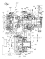
Figure 1 shows a schematic cross-section along a longitudinal/vertical plane of the apparatus according to the present invention; and -
Figure 2 shows an alternative example of embodiment of the device for connecting the apparatus to the combustion engine. - As shown in
Fig. 1 and assuming solely for the sake of convenience of the description and without a limiting meaning a pair of reference axes in the longitudinal direction X-X and transverse direction Y-Y, respectively, as well as a front part corresponding to the part for connecting the auxiliary devices and a rear part opposite to the front part, the hybrid apparatus for transmitting the motive power from amain shaft 2 to a drivenshaft 5 comprises afixed structure 10 having, mounted thereon, abearing 2a which is keyed onto themain shaft 2 which may be rotationally operated by a combustion engine M or by an electric motor which is schematically denoted by 60 with the associated shaft 6a connected in the longitudinal direction to a shaft 6 which is mounted on abearing 410a which is in turn rigidly coupled with thefixed structure 10. - In greater detail the motor M is connected to the
shaft 2 by means of a belt 1 which is endlessly wound around apulley 120 which is integral with theouter ring 121 of afree release mechanism 100 which also comprises afree wheel 122 which is arranged between theouter ring 121 and theshaft 2 so that up to a certain speed of rotation the drivenshaft 2 receives motive power from thepulley 120, while beyond said speed the free release device prevents transmission of the motive power back to the belt 1 as will be understood more clearly below. - The
shaft 2 has, mounted thereon after thefree release device 100, afirst clutch 200 of the electromagnetic type comprising afixed electromagnet 210 mounted between thestructure 10 and abearing 211 which is keyed onto theshaft 2, there being arranged, concentrically with theelectromagnet 210, apulley 220 forming the rotor of the clutch and carrying abelt 201 which is endlessly wound onto a pulley 6b formed on a shaft 6 parallel to the longitudinal direction X-X. - The
clutch 200 also comprises anarmature 230 which is connected via aresilient membrane 231 to a third pulley 3 which is rotationally locked to theshaft 2 and which carries abelt 3a endlessly wound onto apulley 4 mounted onto abearing 4a which is keyed onto the said shaft 6. - The end of the
shaft 2 opposite to that of the free release device has, mounted thereon, an ON/OFF clutch 300 of the electromagnetic type, comprising afixed electromagnet 310, arotor 320 connected to theshaft 2 operated by the apparatus, anarmature 330 connected to adisk 340 via aresilient membrane 330a able to allow displacement in the longitudinal direction of the armature, while preventing relative rotation. - The
armature 330 is recalled against therotor 320 by excitation of theelectromagnet 310. - The
disk 340 can be axially coupled to a drivenshaft 5 to be rotated and forming part of a rotatingdevice 50 which may, for example, be formed by the air-conditioning compressor of a vehicle. - The
armature 430 of anelectromagnetic clutch 400 is connected to thepulley 4 of the secondary shaft 6 via aresilient membrane 430a, said clutch comprising arotor 420 integral with the said shaft 6 and anannular electromagnet 410 which is mounted on abearing 410a keyed onto the secondary shaft 6. - As shown, the shaft 6 is extended in the longitudinal direction beyond the
fixed structure 10 by a section 6a forming the shaft of arotating device 60 which may consist of an electric motor connected to abattery 70. - With such a configuration the operating principle of the hybrid transmission apparatus and the associated rotating devices connected to it is as follows:
- The
shaft 5 of thecompressor 50 is normally at a standstill since theelectromagnetic clutch 300 is kept disengaged so that rotation of theshaft 2 performed by the combustion engine M is not transmitted to the compressor. - If it is required to activate the compressor it is sufficient to excite the
electromagnet 310 of theclutch 300 so as to recall thearmature 330 and transmit the motive power from themain shaft 2 to the drivenshaft 5 and therefore to thecompressor 50 which starts to operate. - Independently of operation of the
compressor 50 it is possible to charge thebatteries 70 by means of theelectric motor 60 which operates in this case as a generator and is rotated by thebelt 3a endlessly wound onto thepulleys 3 and 4 and as an engaging device for theclutch 400 which, exciting theelectromagnet 410, recalls thearmature 430 against therotor 420 which is integral with the shaft 6 and is thus rotated together with the extension 6a of thegenerator 60. - A
control unit 1000 is able to detect when thebatteries 70 are fully charged and deactivate the control circuit of theelectromagnet 410 so as to separate thearmature 430 and reset the shaft 6 to the idle condition. - If powering of the
compressor 50 independently of the combustion engine M is required, it is possible to cause rotation of themain shaft 2 by means of the secondary shaft 6. - In this case the
batteries 70 power theelectric motor 60 which causes rotation of the shaft 6a,6 which, via its pulley 6b and therespective belt 201, causes rotation of therotor 220 mounted on thebearing 221 of theshaft 2. - Recall of the
armature 230 by means of excitation of theelectromagnet 210 of theclutch 200 causes rotation of the pulley 3 which imparts motive power to theshaft 2, said motive power being able to be transmitted to theshaft 5 via theclutch 300 as already described further above. - It is therefore clear how the hybrid transmission apparatus according to the present invention allows operation of the driven
shaft 5 of a rotating device by means of a combustion engine M or, alternately, by means of anelectric motor 60 which is powered bybatteries 70, the apparatus also being able to perform recharging of the batteries by means of the combustion engine independently of operation of the drivenshaft 5. - In order to limit the size of the
electric motor 60 while maintaining the torque necessary for operating the drivenshaft 5 of the rotating device (compressor) connected thereto and to be operated, it is envisaged providing a reduction gear between the pulley 6b of the shaft 6 operated by theelectric motor 60 and thepulley 220 mounted on themain shaft 2, in order to reduce the number of revolutions transmitted by the electric motor, resulting in the greater torque required without altering the dimensions of the electric motor. - It is envisaged, moreover, that the connection between the
main shaft 2 and the combustion engine may be performed by means of anelectromagnetic clutch 1120 instead of via thefree release device 120. - The
clutch 1120 comprises anelectromagnet 1110, arotor 1121 integral with thepulley 1120 actuated by the belt 1 of the combustion engine M, and anarmature 1122 which can be recalled by excitation of the electromagnet so as to connect the rotor to themain shaft 2. - The operating principle of the clutch is conventional per se and therefore not described in detail; in this case also engagement/disengagement of the clutch transmits the motive power to the main shaft or prevents transmission of the motive power back to the belt of the combustion engine.
Claims (23)
- Apparatus for transmitting motive power from a combustion engine (M) or from an electric generator/motor (60) to a driven shaft (5) coupled to a rotating device (50), characterized in that it comprises a main shaft (2), the opposite ends of which are respectively connected to the combustion engine (M) by means of a first engaging/disengaging device (100; 1100) and to the driven shaft (5) by means of a second engaging/disengaging device (300), said shaft (2) having, mounted thereon, a first electromagnetic clutch (200), the rotor (220) of which is able to receive motive power from a secondary shaft (6) which is connected to the motor/generator (60), the main shaft (2) being provided with a pulley (3) carrying a drive belt (3a) which is endlessly wound onto a second pulley (4) mounted idle on said secondary shaft (6) and able to transmit motive power to the generator/motor (60) via an engaging/disengaging device (400).
- Apparatus according to Claim 1, characterized in that said main shaft (2) is mounted on a bearing (2a) rigidly coupled with a fixed structure (10).
- Apparatus according to Claim 1, characterized in that said secondary shaft (6) is parallel to the main shaft (2).
- Apparatus according to Claim 1, characterized in that said secondary shaft (6) is mounted on a bearing (410a) rigidly coupled with the fixed structure (10).
- Apparatus according to Claim 1, characterized in that said first engaging/disengaging device (100) is a free release device.
- Apparatus according to Claim 5, characterized in that said free release device comprises an outer ring (121) carrying a pulley (120) and a free wheel (122) arranged between the outer ring (121) and the main shaft (2).
- Apparatus according to Claim 6, characterized in that the combustion engine (M) is connected to the shaft (2) via a belt (1) endlessly wound onto said pulley (120) of the free release mechanism (100).
- Apparatus according to Claim 1, characterized in that said first coupling is an electromagnetic clutch (1120).
- Apparatus according to Claim 7, characterized in that said electromagnetic clutch (1120) comprises an electromagnet (1110), a rotor (1121) integral with a pulley (1120) actuated by a belt (1) of the combustion engine (M), and an armature (1122) which is able to be axially recalled by excitation of the electromagnet.
- Apparatus according to Claim 1, characterized in that said first electromagnetic clutch (200) is arranged between the first and the second engaging/disengaging devices of the main shaft (2).
- Apparatus according to Claim 1, characterized in that said first electromagnetic clutch (200) comprises a fixed electromagnet (210), a pulley (220) concentric with the electromagnet (210) and forming the rotor of the clutch, and an armature (230) connected via a resilient membrane (231) to a third pulley (3) rotationally locked with the shaft (2).
- Apparatus according to Claim 11, characterized in that said pulley/rotor (220) is connected, via a belt (201), to a pulley (6b) formed on said secondary shaft (6).
- Apparatus according to Claim 8, characterized in that the pulley (6b) of the shaft (6) operated by the electric motor (60) and the pulley (220) mounted on the main shaft (2) form a reduction gear.
- Apparatus according to Claim 1, characterized in that the main shaft (2) has, mounted thereon, a pulley (3) which carries a belt (3a) endlessly wound onto a pulley (4) mounted on a bearing (4a) keyed onto said secondary shaft (6).
- Apparatus according to Claim 14, characterized in that said pulley (3) of the main shaft (2) is arranged after the first electromagnetic clutch (200).
- Apparatus according to Claim 1, characterized in that said second engaging device is an ON/OFF clutch (300).
- Apparatus according to Claim 16, characterized in that said ON/OFF clutch is of the electromagnetic type.
- Apparatus according to Claim 17, characterized in that said clutch (300) of the electromagnetic type comprises a fixed electromagnet (310), a rotor (320) connected to the main shaft (2), and an armature (330) connected to a disk (340) via a resilient membrane (330a).
- Apparatus according to Claim 1, characterized in that said engaging/disengaging device arranged between the secondary shaft (6) and the motor/generator (60) is an electromagnetic clutch (400).
- Apparatus according to Claim 19, characterized in that said electromagnetic clutch (400) comprises a rotor (420) integral with the secondary shaft (6), an annular electromagnetic (410) mounted on a bearing (410a) keyed onto the secondary shaft (6) and an armature (430) connected to the pulley (4) via a resilient membrane (430a).
- Apparatus according to Claim 1, characterized in that said electric motor/generator (60) is connected to rechargeable batteries (70).
- Apparatus according to Claim 21, characterized in that it comprises a control unit (1000) arranged between said batteries (70) and the control circuit of the electromagnet (410) and designed to detect when the batteries (70) are fully charged and emit a signal for disengaging the clutch (400).
- Apparatus according to Claim 1, characterized in that said rotating device (50) is an air-conditioning compressor of a vehicle.
Applications Claiming Priority (1)
| Application Number | Priority Date | Filing Date | Title |
|---|---|---|---|
| IT001893A ITMI20071893A1 (en) | 2007-10-03 | 2007-10-03 | HYBRID EQUIPMENT FOR MOTORCYCLE TRANSMISSION TO A DRIVE SHAFT |
Publications (2)
| Publication Number | Publication Date |
|---|---|
| EP2045113A2 true EP2045113A2 (en) | 2009-04-08 |
| EP2045113A3 EP2045113A3 (en) | 2010-08-11 |
Family
ID=40090514
Family Applications (1)
| Application Number | Title | Priority Date | Filing Date |
|---|---|---|---|
| EP08075796A Withdrawn EP2045113A3 (en) | 2007-10-03 | 2008-10-01 | Hybrid apparatus for transmitting motive power to a driven shaft |
Country Status (3)
| Country | Link |
|---|---|
| US (1) | US20090026035A1 (en) |
| EP (1) | EP2045113A3 (en) |
| IT (1) | ITMI20071893A1 (en) |
Cited By (1)
| Publication number | Priority date | Publication date | Assignee | Title |
|---|---|---|---|---|
| CN111433477A (en) * | 2017-09-30 | 2020-07-17 | 深圳市艾莱茵科技有限公司 | Electromagnetic clutch and gearbox |
Families Citing this family (3)
| Publication number | Priority date | Publication date | Assignee | Title |
|---|---|---|---|---|
| IT1400690B1 (en) * | 2010-04-15 | 2013-06-28 | Baruffaldi Spa | REVERSIBLE ELECTROMAGNETIC DEVICE, DOUBLE ACTION, FOR MOTORCYCLE TRANSMISSION TO / FROM A DUCT / CONDUCTOR ELEMENT |
| KR101665215B1 (en) * | 2011-12-27 | 2016-10-11 | 가츠지 오쿠다 | Wheel-axle generator |
| US11486475B2 (en) * | 2020-08-18 | 2022-11-01 | Illinois Tool Works Inc. | Keyless coupling arrangement for a generator and associated methods |
Family Cites Families (20)
| Publication number | Priority date | Publication date | Assignee | Title |
|---|---|---|---|---|
| US3157260A (en) * | 1961-10-20 | 1964-11-17 | Zahnradfabrik Friedrichshafen | Electromagnetic positive drive clutch |
| US3584715A (en) * | 1970-05-18 | 1971-06-15 | Bendix Corp | Electromagnetic overload clutch |
| US3866729A (en) * | 1973-06-13 | 1975-02-18 | Automatic Research Dev Co | Electromagnetic operated clutches and brakes |
| US4008889A (en) * | 1975-06-16 | 1977-02-22 | Redco, Inc. | Vacuum feed mechanism |
| EP0363367B1 (en) * | 1987-03-21 | 1991-01-16 | ZF FRIEDRICHSHAFEN Aktiengesellschaft | Arrangement of an electromagnet positive clutch |
| DE3808402A1 (en) * | 1988-03-12 | 1989-09-21 | Opel Adam Ag | DIFFERENTIAL GEARBOXES FOR THE DRIVE AXLES OF MOTOR VEHICLES |
| JPH09267647A (en) * | 1996-04-02 | 1997-10-14 | Honda Motor Co Ltd | Power transmission mechanism of hybrid vehicle |
| US5853343A (en) * | 1996-09-05 | 1998-12-29 | Ford Global Technologies, Inc. | Dual mode continually variable transmission |
| US6048288A (en) * | 1997-11-18 | 2000-04-11 | Toyota Jidosha Kabushiki Kaisha | Power train system for a vehicle and method for operating same |
| US6550702B2 (en) * | 2000-02-29 | 2003-04-22 | William R Champlin | Apparatus for removing and chipping wood scraps |
| JP4173345B2 (en) * | 2002-10-03 | 2008-10-29 | 本田技研工業株式会社 | Vehicle drive device |
| ITTO20030878A1 (en) * | 2003-11-05 | 2005-05-06 | Fiat Ricerche | MOTORCYCLE TRANSMISSION SYSTEM BETWEEN THE CRANKSHAFT OF A MOTOR WITH INTERNAL COMBUSTION OF A MOTOR VEHICLE AND A GROUP OF AUXILIARY DEVICES. |
| US7316628B2 (en) * | 2004-01-13 | 2008-01-08 | The Gates Corporation Ip Law Dept. | Two speed transmission and belt drive system |
| ITTO20050288A1 (en) * | 2005-04-29 | 2006-10-30 | Mauro Palitto | START-STOP CONTROL UNIT FOR A MOTOR VEHICLE |
| US7748214B2 (en) * | 2006-03-03 | 2010-07-06 | Nissan Motor Co., Ltd. | Exhaust gas purification system for hybrid vehicle |
| US7611004B2 (en) * | 2006-08-07 | 2009-11-03 | Deere & Company | Control system and method for controlling an operational mode of a vehicle via multiple clutch assemblies |
| US7753147B2 (en) * | 2007-01-31 | 2010-07-13 | Gm Global Technology Operations, Inc. | Vehicle drive system, power management device, and method for managing power |
| JP4311754B2 (en) * | 2007-06-21 | 2009-08-12 | 三菱電機株式会社 | Vehicle drive device |
| US9102225B2 (en) * | 2007-10-31 | 2015-08-11 | GM Global Technology Operations LLC | Air conditioning for belt-alternator-starter hybrid electric vehicle |
| US8808124B2 (en) * | 2008-04-15 | 2014-08-19 | GM Global Technology Operations LLC | Belt alternator starter systems for hybrid vehicles |
-
2007
- 2007-10-03 IT IT001893A patent/ITMI20071893A1/en unknown
-
2008
- 2008-10-01 EP EP08075796A patent/EP2045113A3/en not_active Withdrawn
- 2008-10-03 US US12/244,823 patent/US20090026035A1/en not_active Abandoned
Cited By (2)
| Publication number | Priority date | Publication date | Assignee | Title |
|---|---|---|---|---|
| CN111433477A (en) * | 2017-09-30 | 2020-07-17 | 深圳市艾莱茵科技有限公司 | Electromagnetic clutch and gearbox |
| CN111433477B (en) * | 2017-09-30 | 2022-01-07 | 深圳市艾莱茵科技有限公司 | Electromagnetic clutch and gearbox |
Also Published As
| Publication number | Publication date |
|---|---|
| EP2045113A3 (en) | 2010-08-11 |
| ITMI20071893A1 (en) | 2009-04-04 |
| US20090026035A1 (en) | 2009-01-29 |
Similar Documents
| Publication | Publication Date | Title |
|---|---|---|
| JP3682964B2 (en) | Vehicle drive device | |
| EP2514620B1 (en) | Accessory drive mechanism for hybrid vehicle | |
| US6656083B2 (en) | Hybrid drive system | |
| CN105383278B (en) | Power assembly with engine start and braking mode | |
| EP1529957B1 (en) | "A system for transmitting motion between the shaft of an internal combustion engine of a motor vehicle and a group of auxiliary devices" | |
| EP1314884B1 (en) | Engine system, operating method therefor, and engine starting apparatus | |
| US8479847B2 (en) | Breakaway clutch for controllable speed accessory drive system | |
| US7695400B2 (en) | Speed-limiting accessory drive system and method of controlling speed of a driven accessory | |
| US20110233020A1 (en) | Power transmission device for hybrid vehicle | |
| JP5805784B2 (en) | Drive device for vehicle auxiliary device | |
| WO2009017978A1 (en) | Hybrid powertrain with efficient electric-only mode | |
| WO2014144320A1 (en) | Alternator-starter assembly having gear reduction system | |
| CN110315964B (en) | Vehicle drive device | |
| US9018867B2 (en) | Generator drive system for an internal combustion engine | |
| US10046635B2 (en) | Powertrain for a hybrid type vehicle | |
| EP2045113A2 (en) | Hybrid apparatus for transmitting motive power to a driven shaft | |
| US20090149290A1 (en) | Method for charging a battery of a hybrid vehicle at rest | |
| JP3368669B2 (en) | Motor generator for vehicles | |
| WO2010131942A1 (en) | Transmission system | |
| SE515756C2 (en) | Power units for motor vehicles | |
| CN109703349A (en) | Multi-mode hybrid speed change system | |
| JP4872880B2 (en) | Power output device | |
| EP1084049A1 (en) | Hybrid propulsor with braking energy recovery, particularly for motorcycles | |
| SE529460C2 (en) | Power transmission system for a hybrid powered motor vehicle | |
| JP4399706B2 (en) | Auxiliary equipment for idle stop vehicles |
Legal Events
| Date | Code | Title | Description |
|---|---|---|---|
| PUAI | Public reference made under article 153(3) epc to a published international application that has entered the european phase |
Free format text: ORIGINAL CODE: 0009012 |
|
| AK | Designated contracting states |
Kind code of ref document: A2 Designated state(s): AT BE BG CH CY CZ DE DK EE ES FI FR GB GR HR HU IE IS IT LI LT LU LV MC MT NL NO PL PT RO SE SI SK TR |
|
| AX | Request for extension of the european patent |
Extension state: AL BA MK RS |
|
| PUAL | Search report despatched |
Free format text: ORIGINAL CODE: 0009013 |
|
| AK | Designated contracting states |
Kind code of ref document: A3 Designated state(s): AT BE BG CH CY CZ DE DK EE ES FI FR GB GR HR HU IE IS IT LI LT LU LV MC MT NL NO PL PT RO SE SI SK TR |
|
| AX | Request for extension of the european patent |
Extension state: AL BA MK RS |
|
| AKY | No designation fees paid | ||
| REG | Reference to a national code |
Ref country code: DE Ref legal event code: R108 Effective date: 20110322 Ref country code: DE Ref legal event code: 8566 |
|
| STAA | Information on the status of an ep patent application or granted ep patent |
Free format text: STATUS: THE APPLICATION IS DEEMED TO BE WITHDRAWN |
|
| 18D | Application deemed to be withdrawn |
Effective date: 20110212 |