EP2045035A2 - Inorganic fiber mat, holding sealer, sound absorber, and method for manufacturing inorganic fiber mat - Google Patents
Inorganic fiber mat, holding sealer, sound absorber, and method for manufacturing inorganic fiber mat Download PDFInfo
- Publication number
- EP2045035A2 EP2045035A2 EP08004854A EP08004854A EP2045035A2 EP 2045035 A2 EP2045035 A2 EP 2045035A2 EP 08004854 A EP08004854 A EP 08004854A EP 08004854 A EP08004854 A EP 08004854A EP 2045035 A2 EP2045035 A2 EP 2045035A2
- Authority
- EP
- European Patent Office
- Prior art keywords
- inorganic fiber
- laser
- fiber mat
- aggregated body
- cut
- Prior art date
- Legal status (The legal status is an assumption and is not a legal conclusion. Google has not performed a legal analysis and makes no representation as to the accuracy of the status listed.)
- Withdrawn
Links
Images


Classifications
-
- C—CHEMISTRY; METALLURGY
- C04—CEMENTS; CONCRETE; ARTIFICIAL STONE; CERAMICS; REFRACTORIES
- C04B—LIME, MAGNESIA; SLAG; CEMENTS; COMPOSITIONS THEREOF, e.g. MORTARS, CONCRETE OR LIKE BUILDING MATERIALS; ARTIFICIAL STONE; CERAMICS; REFRACTORIES; TREATMENT OF NATURAL STONE
- C04B41/00—After-treatment of mortars, concrete, artificial stone or ceramics; Treatment of natural stone
- C04B41/009—After-treatment of mortars, concrete, artificial stone or ceramics; Treatment of natural stone characterised by the material treated
-
- F—MECHANICAL ENGINEERING; LIGHTING; HEATING; WEAPONS; BLASTING
- F01—MACHINES OR ENGINES IN GENERAL; ENGINE PLANTS IN GENERAL; STEAM ENGINES
- F01N—GAS-FLOW SILENCERS OR EXHAUST APPARATUS FOR MACHINES OR ENGINES IN GENERAL; GAS-FLOW SILENCERS OR EXHAUST APPARATUS FOR INTERNAL-COMBUSTION ENGINES
- F01N3/00—Exhaust or silencing apparatus having means for purifying, rendering innocuous, or otherwise treating exhaust
- F01N3/08—Exhaust or silencing apparatus having means for purifying, rendering innocuous, or otherwise treating exhaust for rendering innocuous
- F01N3/10—Exhaust or silencing apparatus having means for purifying, rendering innocuous, or otherwise treating exhaust for rendering innocuous by thermal or catalytic conversion of noxious components of exhaust
- F01N3/24—Exhaust or silencing apparatus having means for purifying, rendering innocuous, or otherwise treating exhaust for rendering innocuous by thermal or catalytic conversion of noxious components of exhaust characterised by constructional aspects of converting apparatus
- F01N3/28—Construction of catalytic reactors
-
- B—PERFORMING OPERATIONS; TRANSPORTING
- B23—MACHINE TOOLS; METAL-WORKING NOT OTHERWISE PROVIDED FOR
- B23K—SOLDERING OR UNSOLDERING; WELDING; CLADDING OR PLATING BY SOLDERING OR WELDING; CUTTING BY APPLYING HEAT LOCALLY, e.g. FLAME CUTTING; WORKING BY LASER BEAM
- B23K26/00—Working by laser beam, e.g. welding, cutting or boring
- B23K26/36—Removing material
- B23K26/38—Removing material by boring or cutting
-
- C—CHEMISTRY; METALLURGY
- C04—CEMENTS; CONCRETE; ARTIFICIAL STONE; CERAMICS; REFRACTORIES
- C04B—LIME, MAGNESIA; SLAG; CEMENTS; COMPOSITIONS THEREOF, e.g. MORTARS, CONCRETE OR LIKE BUILDING MATERIALS; ARTIFICIAL STONE; CERAMICS; REFRACTORIES; TREATMENT OF NATURAL STONE
- C04B41/00—After-treatment of mortars, concrete, artificial stone or ceramics; Treatment of natural stone
- C04B41/0072—Heat treatment
-
- F—MECHANICAL ENGINEERING; LIGHTING; HEATING; WEAPONS; BLASTING
- F01—MACHINES OR ENGINES IN GENERAL; ENGINE PLANTS IN GENERAL; STEAM ENGINES
- F01N—GAS-FLOW SILENCERS OR EXHAUST APPARATUS FOR MACHINES OR ENGINES IN GENERAL; GAS-FLOW SILENCERS OR EXHAUST APPARATUS FOR INTERNAL-COMBUSTION ENGINES
- F01N3/00—Exhaust or silencing apparatus having means for purifying, rendering innocuous, or otherwise treating exhaust
- F01N3/08—Exhaust or silencing apparatus having means for purifying, rendering innocuous, or otherwise treating exhaust for rendering innocuous
- F01N3/10—Exhaust or silencing apparatus having means for purifying, rendering innocuous, or otherwise treating exhaust for rendering innocuous by thermal or catalytic conversion of noxious components of exhaust
- F01N3/24—Exhaust or silencing apparatus having means for purifying, rendering innocuous, or otherwise treating exhaust for rendering innocuous by thermal or catalytic conversion of noxious components of exhaust characterised by constructional aspects of converting apparatus
-
- B—PERFORMING OPERATIONS; TRANSPORTING
- B23—MACHINE TOOLS; METAL-WORKING NOT OTHERWISE PROVIDED FOR
- B23K—SOLDERING OR UNSOLDERING; WELDING; CLADDING OR PLATING BY SOLDERING OR WELDING; CUTTING BY APPLYING HEAT LOCALLY, e.g. FLAME CUTTING; WORKING BY LASER BEAM
- B23K2101/00—Articles made by soldering, welding or cutting
- B23K2101/006—Vehicles
-
- B—PERFORMING OPERATIONS; TRANSPORTING
- B23—MACHINE TOOLS; METAL-WORKING NOT OTHERWISE PROVIDED FOR
- B23K—SOLDERING OR UNSOLDERING; WELDING; CLADDING OR PLATING BY SOLDERING OR WELDING; CUTTING BY APPLYING HEAT LOCALLY, e.g. FLAME CUTTING; WORKING BY LASER BEAM
- B23K2101/00—Articles made by soldering, welding or cutting
- B23K2101/04—Tubular or hollow articles
-
- B—PERFORMING OPERATIONS; TRANSPORTING
- B23—MACHINE TOOLS; METAL-WORKING NOT OTHERWISE PROVIDED FOR
- B23K—SOLDERING OR UNSOLDERING; WELDING; CLADDING OR PLATING BY SOLDERING OR WELDING; CUTTING BY APPLYING HEAT LOCALLY, e.g. FLAME CUTTING; WORKING BY LASER BEAM
- B23K2103/00—Materials to be soldered, welded or cut
- B23K2103/16—Composite materials
-
- B—PERFORMING OPERATIONS; TRANSPORTING
- B23—MACHINE TOOLS; METAL-WORKING NOT OTHERWISE PROVIDED FOR
- B23K—SOLDERING OR UNSOLDERING; WELDING; CLADDING OR PLATING BY SOLDERING OR WELDING; CUTTING BY APPLYING HEAT LOCALLY, e.g. FLAME CUTTING; WORKING BY LASER BEAM
- B23K2103/00—Materials to be soldered, welded or cut
- B23K2103/30—Organic materials
- B23K2103/38—Fabrics; Fibrous materials
-
- B—PERFORMING OPERATIONS; TRANSPORTING
- B23—MACHINE TOOLS; METAL-WORKING NOT OTHERWISE PROVIDED FOR
- B23K—SOLDERING OR UNSOLDERING; WELDING; CLADDING OR PLATING BY SOLDERING OR WELDING; CUTTING BY APPLYING HEAT LOCALLY, e.g. FLAME CUTTING; WORKING BY LASER BEAM
- B23K2103/00—Materials to be soldered, welded or cut
- B23K2103/50—Inorganic materials other than metals or composite materials
-
- F—MECHANICAL ENGINEERING; LIGHTING; HEATING; WEAPONS; BLASTING
- F01—MACHINES OR ENGINES IN GENERAL; ENGINE PLANTS IN GENERAL; STEAM ENGINES
- F01N—GAS-FLOW SILENCERS OR EXHAUST APPARATUS FOR MACHINES OR ENGINES IN GENERAL; GAS-FLOW SILENCERS OR EXHAUST APPARATUS FOR INTERNAL-COMBUSTION ENGINES
- F01N3/00—Exhaust or silencing apparatus having means for purifying, rendering innocuous, or otherwise treating exhaust
- F01N3/08—Exhaust or silencing apparatus having means for purifying, rendering innocuous, or otherwise treating exhaust for rendering innocuous
- F01N3/10—Exhaust or silencing apparatus having means for purifying, rendering innocuous, or otherwise treating exhaust for rendering innocuous by thermal or catalytic conversion of noxious components of exhaust
- F01N3/24—Exhaust or silencing apparatus having means for purifying, rendering innocuous, or otherwise treating exhaust for rendering innocuous by thermal or catalytic conversion of noxious components of exhaust characterised by constructional aspects of converting apparatus
- F01N3/28—Construction of catalytic reactors
- F01N3/2839—Arrangements for mounting catalyst support in housing, e.g. with means for compensating thermal expansion or vibration
- F01N3/2853—Arrangements for mounting catalyst support in housing, e.g. with means for compensating thermal expansion or vibration using mats or gaskets between catalyst body and housing
-
- Y—GENERAL TAGGING OF NEW TECHNOLOGICAL DEVELOPMENTS; GENERAL TAGGING OF CROSS-SECTIONAL TECHNOLOGIES SPANNING OVER SEVERAL SECTIONS OF THE IPC; TECHNICAL SUBJECTS COVERED BY FORMER USPC CROSS-REFERENCE ART COLLECTIONS [XRACs] AND DIGESTS
- Y10—TECHNICAL SUBJECTS COVERED BY FORMER USPC
- Y10T—TECHNICAL SUBJECTS COVERED BY FORMER US CLASSIFICATION
- Y10T428/00—Stock material or miscellaneous articles
- Y10T428/29—Coated or structually defined flake, particle, cell, strand, strand portion, rod, filament, macroscopic fiber or mass thereof
- Y10T428/2913—Rod, strand, filament or fiber
- Y10T428/2915—Rod, strand, filament or fiber including textile, cloth or fabric
-
- Y—GENERAL TAGGING OF NEW TECHNOLOGICAL DEVELOPMENTS; GENERAL TAGGING OF CROSS-SECTIONAL TECHNOLOGIES SPANNING OVER SEVERAL SECTIONS OF THE IPC; TECHNICAL SUBJECTS COVERED BY FORMER USPC CROSS-REFERENCE ART COLLECTIONS [XRACs] AND DIGESTS
- Y10—TECHNICAL SUBJECTS COVERED BY FORMER USPC
- Y10T—TECHNICAL SUBJECTS COVERED BY FORMER US CLASSIFICATION
- Y10T428/00—Stock material or miscellaneous articles
- Y10T428/29—Coated or structually defined flake, particle, cell, strand, strand portion, rod, filament, macroscopic fiber or mass thereof
- Y10T428/2913—Rod, strand, filament or fiber
- Y10T428/2929—Bicomponent, conjugate, composite or collateral fibers or filaments [i.e., coextruded sheath-core or side-by-side type]
-
- Y—GENERAL TAGGING OF NEW TECHNOLOGICAL DEVELOPMENTS; GENERAL TAGGING OF CROSS-SECTIONAL TECHNOLOGIES SPANNING OVER SEVERAL SECTIONS OF THE IPC; TECHNICAL SUBJECTS COVERED BY FORMER USPC CROSS-REFERENCE ART COLLECTIONS [XRACs] AND DIGESTS
- Y10—TECHNICAL SUBJECTS COVERED BY FORMER USPC
- Y10T—TECHNICAL SUBJECTS COVERED BY FORMER US CLASSIFICATION
- Y10T442/00—Fabric [woven, knitted, or nonwoven textile or cloth, etc.]
- Y10T442/60—Nonwoven fabric [i.e., nonwoven strand or fiber material]
- Y10T442/659—Including an additional nonwoven fabric
- Y10T442/67—Multiple nonwoven fabric layers composed of the same inorganic strand or fiber material
-
- Y—GENERAL TAGGING OF NEW TECHNOLOGICAL DEVELOPMENTS; GENERAL TAGGING OF CROSS-SECTIONAL TECHNOLOGIES SPANNING OVER SEVERAL SECTIONS OF THE IPC; TECHNICAL SUBJECTS COVERED BY FORMER USPC CROSS-REFERENCE ART COLLECTIONS [XRACs] AND DIGESTS
- Y10—TECHNICAL SUBJECTS COVERED BY FORMER USPC
- Y10T—TECHNICAL SUBJECTS COVERED BY FORMER US CLASSIFICATION
- Y10T442/00—Fabric [woven, knitted, or nonwoven textile or cloth, etc.]
- Y10T442/60—Nonwoven fabric [i.e., nonwoven strand or fiber material]
- Y10T442/69—Autogenously bonded nonwoven fabric
Definitions
- the present invention relates to an inorganic fiber mat, and more specifically to a structure for reducing scattering of fibers in an inorganic fiber mat.
- a catalyst converter has been used as an exhaust gas purifying apparatus that purifies exhaust gases discharged from an internal combustion engine.
- the catalyst converter generally includes a holding sealer interposed between a catalyst supporting carrier (exhaust gas treatment unit) on which a catalyst is supported and a metallic shell (casing) that accommodates the catalyst supporting carrier.
- a catalyst supporting carrier exhaust gas treatment unit
- a metallic shell casing
- an inorganic fiber mat is sometimes employed which is made of ceramic fibers such as alumina-silica-based ones and that is impregnated with an organic binder and molded into a mat shape having a predetermined thickness.
- the holding sealer serves for thermal insulation, prevents leakage of unpurified exhaust gases through between the shell and the catalyst supporting carrier, and also prevents damage caused by contact between the shell and the catalyst supporting carrier.
- inorganic fibers that form the holding sealer are fine fibers. Therefore, in assembling the catalyst converter, fibers may scatter away from a surface of the holding sealer to undesirably worsen working conditions.
- Patent Document 1 discloses that, in an alumina fiber aggregate, scattering of alumina short fibers can be suppressed by controlling an average fiber diameter and a minimum fiber diameter to a specific range.
- Patent Document 2 discloses that the alumina fiber aggregate disclosed in Patent Document 1 is used as the holding sealer to thereby suppress an amount of scattering of inorganic fibers caused in assembling a catalyst converter. In addition, Patent Document 2 discloses scattering of inorganic fibers can be suppressed also by increasing an amount of organic binder contained the holding sealer.
- Patent Document 1 JP-A 2003-105658
- Patent Document 2 JP-A 2006-342774
- Patent Document 1 Even an alumina fiber aggregate having an average fiber diameter and a minimum fiber diameter controlled to a specific range as disclosed in Patent Document 1 cannot sufficiently reduce an amount of scattering of inorganic fibers, and still leaves room for improvement.
- An object of the present invention is to provide an inorganic fiber mat that is able to well reduce scattering of fibers not by increasing an amount of organic binder and is suitable for use as a holding sealer or the like.
- an inorganic fiber mat formed by cutting an inorganic fiber aggregated body, wherein inorganic fibers existing on at least part of a surface of the inorganic fiber aggregated body are heat-treated and fused to one another.
- the fibers are less likely to scatter.
- scattering of fibers away from the inorganic fiber mat can be effectively reduced.
- end portions of fibers exposed on the surface are melted and changed into rounded shapes. Accordingly, a sense of irritation and a feeling of discomfort, which may arise when the surface is touched with a hand, can be reduced.
- scattering of fibers can be reduced well without increasing an amount of organic binder, the inorganic fiber mat can be easily adapted to needs for a less amount of organic binder.
- a crystallization rate of the heat-treated surface is preferably 80% or less.
- an inorganic fiber mat formed by cutting an inorganic fiber aggregated body, wherein a rounded melted portion is formed on at least part of a surface of the inorganic fiber aggregated body, and at least part of fibers exposed on the surface is cross-linked by the melted portion.
- the fibers exposed on the surface can be cross-linked together by the rounded melted portion. Accordingly, scattering of fibers away from the surface can be suppressed well, and in addition a sense of irritation and a feeling of discomfort caused when the surface is touched with a hand can be reduced.
- the inorganic fiber aggregated body is preferably cut by a laser.
- the inorganic fiber mat can be easily manufactured.
- the cut surface from which fibers are likely to scatter away
- the cut surface is thoroughly heat-treated. Accordingly, fibers existing on the whole cut surface can surely be melted, and scattering of fibers can be reduced effectively.
- inorganic fiber aggregated bodies are superimposed on one another and simultaneously cut by the laser.
- the plurality of inorganic fiber aggregated bodies can be cut at one time, and cut surfaces thereof can be heat-treated. This further improves manufacturing efficiency.
- non-contact laser cutting is employed, even when a plurality of inorganic fiber aggregated bodies are superimposed on one another and a thickness becomes larger, they can be cut into an accurate size.
- a laser-irradiation treatment is preferably performed on at least part of a surface of the inorganic fiber aggregated body other than a cut surface of the inorganic fiber aggregated body.
- Examples of the laser used for cutting the inorganic fiber aggregated body and the like include a carbon dioxide gas laser, a YAG laser, an excimer laser, an He-Ne laser, a fiber laser, and a diode laser.
- a holding sealer including the inorganic fiber mat, which is disposed between an exhaust gas treatment unit and a casing of an exhaust gas purifying apparatus.
- an amount of organic binder can be reduced, increase in hardness of the holding sealer can be avoided, resulting in excellent workability in assembling.
- a problem of odors generated when the organic binder burns at an initial use of the exhaust gas purifying apparatus, and the like, can be suppressed.
- a sound absorber of a vehicle muffler including the inorganic fiber mat.
- an amount of organic binder can be reduced, increase in hardness of the sound absorber can be avoided, resulting in excellent workability in assembling.
- a problem of odors generated when the organic binder burns at an initial use of the vehicle muffler, and the like, can be suppressed.
- a method for manufacturing an inorganic fiber mat comprising: cutting an inorganic fiber aggregated body; and heat-treating at least part of a surface of the inorganic fiber aggregated body.
- the fibers are less likely to scatter.
- scattering of fibers away from the inorganic fiber mat can be effectively reduced.
- end portions of fibers exposed on the surface are melted and changed into rounded shapes. Accordingly, a sense of irritation and a feeling of discomfort, which may arise when the surface is touched with a hand, can be reduced.
- scattering of fibers can be reduced well without increasing an amount of organic binder, the inorganic fiber mat can be easily adapted to needs for a less amount of organic binder.
- the inorganic fiber aggregated body is preferably laser-cut so that the cutting and the heat-treating are performed at one time.
- the inorganic fiber mat can be easily manufactured.
- the cut surface from which fibers are likely to scatter away
- the cut surface is thoroughly heat-treated. Accordingly, fibers existing on the whole cut surface can surely be melted, and scattering of fibers can be reduced effectively.
- a plurality of the inorganic fiber aggregated bodies are superimposed on one another and simultaneously cut by the laser.
- inorganic fiber mats can be cut at one time, and cut surfaces thereof can be heat-treated. This further improves manufacturing efficiency.
- non-contact laser cutting is employed, even when a plurality of inorganic fiber aggregated bodies are superimposed on one another and a thickness becomes larger, they can be cut into an accurate size.
- the heat-treating preferably includes performing a laser-irradiation treatment on at least part of a surface of the inorganic fiber aggregated body other than a cut surface of the inorganic fiber aggregated body obtained in the cutting.
- Examples of the laser used in the heat-treating include a carbon dioxide gas laser, a YAG laser, an excimer laser, an He-Ne laser, a fiber laser, and a diode laser.
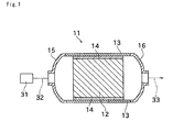
- Fig. 1 is a schematic sectional view of a catalyst converter including a holding sealer according to an embodiment of the present invention.
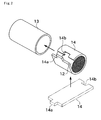
- Fig. 2 is a perspective view for describing assembling of a catalyst supporting carrier to a shell of a catalyst converter.
- Fig. 3 is a perspective view schematically illustrating that the holding sealer is being cut by a carbon dioxide gas laser.
- a catalyst converter (exhaust gas purifying apparatus) 11 of the present embodiment includes a catalyst supporting carrier (exhaust gas treatment unit) 12, a shell (casing) 13 that accommodates the catalyst supporting carrier 12, and a holding sealer 14 that is interposed between the catalyst supporting carrier 12 and the shell 13.
- the catalyst supporting carrier 12 is formed into a round pillar shape, for example, and has a honeycomb structure with many cells formed therein.
- the catalyst supporting carrier 12 is made of ceramics such as silicon carbide, silicon nitride, cordierite, and mullite. Wall surfaces of the cells of the catalyst supporting carrier 12 are coated with a catalyst such as platinum, palladium, and rhodium, so that toxic substances contained in exhaust gases of a vehicle engine (internal combustion engine) 31 are detoxified when the exhaust gases pass through the cells of the catalyst supporting carrier 12.
- the holding sealer 14 has a substantially rectangular shape, and a length (longitudinal length) of the holding sealer 14 is substantially equal to an outer circumference of the catalyst supporting carrier 12.
- a protrusion 14a is formed at one longitudinal end of the holding sealer 14, and a recess 14b is formed at the other longitudinal end of the holding sealer 14.
- a contour shape of the protrusion 14a and a contour shape of the recess 14b correspond to each other, so that the recess 14b and the protrusion 14a can be fitted with each other.
- the holding sealer 14 is made of an inorganic fiber mat obtained by cutting an inorganic fiber aggregated body into a predetermined shape.
- the shell 13 has a cylindrical shape with its both ends opened, and an inside diameter of the shell 13 is slightly larger than an outside diameter of the catalyst supporting carrier 12.
- the shell 13 is made of a metal material.
- the holding sealer 14 is wound around an outer surface of the catalyst supporting carrier 12.
- the protrusion 14a of the holding sealer 14 is fitted to the recess 14b thereof, so that longitudinal end portions of the holding sealer 14 are connected to each other to thereby form the holding sealer 14 into an endless shape.
- the catalyst supporting carrier 12 having the holding sealer 14 wound thereon is press-fitted into the shell 13 by use of elasticity of the holding sealer 14.
- exhaust pipe joints 15 and 16 are connected to the respective openings, formed at both ends of the shell 13, by welding, for example.
- One exhaust pipe joint 15 is connected, through an exhaust pipe 32 schematically illustrated with a broken line, to an exhaust port of the vehicle engine 31.
- the other exhaust pipe joint 16 is connected through an exhaust pipe 33 to a sound-reducing muffler not shown.
- the holding sealer 14 is obtained by cutting an inorganic fiber aggregated body 21 into a predetermined shape using a carbon dioxide gas laser processing machine 41, and irradiating faces (front surface and back surface) of the inorganic fiber aggregated body 21 other than its cut surface with a scanning laser of the carbon dioxide gas laser processing machine 41.
- the inorganic fiber aggregated body 21 include silica fibers, alumina fibers, alumina-silica-based fibers, and the like, which have been molded into a mat shape having a predetermined thickness.
- a possible thickness of the inorganic fiber aggregated body 21 is 5 to 20 mm, for example.
- the inorganic fiber aggregated body 21 may be impregnated with an appropriate binder resin (e.g., an organic binder) for bonding fibers thereof.
- an appropriate binder resin e.g., an organic binder
- the inorganic fiber aggregated body 21 may undergo a known needling process for improving durability and strength thereof.
- the carbon dioxide gas laser processing machine 41 shown in Fig. 3 generates a laser beam by a not-shown laser oscillator, and the laser beam 42 is transmitted to a beam condenser 43 through an optical path formed by a reflecting mirror or the like.
- a condenser lens 44 is disposed in the beam condenser 43.
- the laser beam 42 is converged by means of the condenser lens 44 and applied from a nozzle 45, to melt and cut the inorganic fiber aggregated body 21, which serves as a workpiece.
- a surface of the inorganic fiber aggregated body 21 can be heat-treated without the inorganic fiber aggregated body 21 being cut.
- a plurality of inorganic fiber aggregated bodies 21 that are superimposed on one another are set on the carbon dioxide gas laser processing machine 41, and cut into a shape of the holding sealer 14 shown in Fig. 2 .
- a plurality of semi-finished products that have been cut into a predetermined shape and whose cut surface has been heat-treated can be obtained at one time.
- the inorganic fiber aggregated bodies 21 thus cut and heat-treated are set on the carbon dioxide gas laser processing machine 41 one by one, and a front surface and a back surface of the inorganic fiber aggregated body 21 are scanned with the laser beam 42 in a state where there is a sufficiently more space between the nozzle 45 and the inorganic fiber aggregated body 21 than in cutting.
- faces of the inorganic fiber aggregated body 21 other than the cut surface faces thereof facing in a thickness direction of the inorganic fiber mat
- Surfaces (the cut surface, the front surface, and the back surface) of the inorganic fiber mat thus obtained exhibit a crystallization rate of 80% or less.
- a side face (cut surface), a front surface, and a back surface of the holding sealer 14 which is made of the inorganic fiber mat obtained in the above-described manner, fibers are melt and fused to other fibers so that scattering of fibers can be suppressed. This can improve working conditions in assembling the catalyst converter 11 as shown in Fig. 2 . Moreover, there will be less fiber of the holding sealer 14 that has its end portion sharpened like a needle and exposed on the surface. Therefore, a sense of irritation and a feeling of discomfort, which may arise in an operator upon touching the holding sealer 14 during an assembling operation and the like, can be reduced.
- Fig. 4(a) is a scanning micrograph showing a cut surface of an inorganic fiber aggregated body 21 cut by laser-cutting.
- Fig. 4 (b) is a scanning micrograph showing a cut surface of the inorganic fiber aggregated body 21 cut by a punching blade.
- the inorganic fiber aggregated body 21 When the inorganic fiber aggregated body 21 is cut by a punching blade, it is observed that many of thin fibers forming the mat are cut so that their end portions are exposed on the cut surface, as shown in Fig. 4(b) .
- the micrograph shown in Fig. 4(b) indicates that, in a case where the inorganic fiber aggregated body 21 is cut by a punching blade, fibers shortened by cutting are easily separated from a cut surface.
- the inorganic fiber aggregated body 21 is cut by laser-cutting, it is observed that many melted portions having various sizes, which are formed by melted fibers, appear over the entire region of the cut surface, as shown in Fig. 4(a) .
- a larger melted portion extends over a plurality of fibers and adheres.
- Many larger melted portions have flat, crushed shapes in a direction perpendicular to the cut surface.
- fibers exposed on the cut surface are observed to be fused to one another, to form a cross-linked structure. It is also observed that, on the cut surface, most of end portions of fibers are melted and changed into a rounded, a little swollen shape.
- Samples for the fiber scattering property tests were prepared using an inorganic fiber aggregated body manufactured by Mitsubishi Chemical Functional Products, Inc. (trade name: MAFTEC Blankest)
- MAFTEC Blanket is a mat-molded inorganic fiber aggregated body containing 72% by weight of alumina and 28% by weight of silica. Its average fiber diameter is 5 ⁇ m, its organic component is 0%, a specific gravity of its surface is 1160 g/cm 2 , and its thickness is approximately 7.1 mm.
- samples were prepared by cutting the above-mentioned inorganic fiber aggregated body by the carbon dioxide gas laser processing machine 41 as shown in Fig. 3 .
- the carbon dioxide gas laser processing machine 41 used herein has a rated power output of 1 kW, a wavelength of 10.6 ⁇ m, a minimum condensed beam diameter of 100 ⁇ m, and a maximum processing speed of 30 m/min.
- a power output was set to 100 W
- a wavelength was set to 10.6 ⁇ m
- a condensed beam diameter was set to 100 to 200 ⁇ m.
- a laser output for cutting the inorganic fiber aggregated body 21 was variously changed to thereby prepare four samples (first to fourth samples).
- a laser output for cutting was 50 W for the first sample, 100 W for the second sample, 200 W for the third sample, and 300 W for the fourth sample.
- a processing speed was 500 mm/min, and a distance between the inorganic fiber aggregated body 21 and the nozzle 45 for applying a laser beam was 1 mm.
- a fifth sample was prepared by cutting the inorganic fiber aggregated body 21 by a punching blade
- a sixth sample was prepared by cutting the inorganic fiber aggregated body 21 by a punching blade and then sealing a cut surface thereof with an adhesive tape.
- Each of the first to sixth samples was cut into a square shape of 100 mm x 100 mm.
- the test equipment 51 has a support column 53 installed vertically on a base 52, and a sample support arm 54 rotatably pivoted at an upper end portion of the support column 53.
- a length of the sample support arm 54 is 92 cm.
- a scale plate 55 that indicates a lift angle of the sample support arm 54 is attached to the support column 53.
- a vertical wall member 56 is fixed at a position collidable with the sample support arm 54.
- the sample support arm 54 is brought into a horizontal position (with the lift angle of 90°), and locked by an appropriate locking mechanism. Then, the above-described sample 60 is fixed at a tip end portion (at an portion approximately 82 to 92 cm distant from a center of rotation) of the sample support arm 54, and locking by the locking mechanism is released. Thus, the sample support arm 54 rotates downward due to its own weight. At a time when the sample support arm 54 takes a vertical position as illustrated with broken lines, the sample support arm 54 collides with the vertical wall member 56 fixed to the support column 53. An amount of fibers scattering away from the sample 60 during the rotation and collision of the sample support arm 54 (fiber scattering amount) is calculated based on a change in weight of the sample 60 between before and after this operation.
- fiber scattering amount is calculated based on a change in weight of the sample 60 between before and after this operation.
- any of the first to fourth samples which were laser-cut are greatly improved in a fiber scattering rate, as compared with the fifth sample which was cut by the punching blade.
- the output of 50 W (for the first sample) was the best with respect the fiber scattering rate.
- a mullite content of a cut surface was measured, to calculate a crystallization rate.
- diameters of the respective portions (melted portions) of a cut surface where fibers were melted and formed substantially spherical shapes were also measured, to calculate an average value.
- the crystallization rate was calculated as follows. A portion of the cut surface of the inorganic fiber aggregated body was taken, powdered using a mortar, and underwent an X-ray diffraction analysis. In an X-ray diffractometer used in this diffraction, an X-ray source is a CuK ⁇ ray, and an X-ray output is 40 kV, 20 mA. The target diffraction lines were a diffraction line of mullite (16.4°) and a diffraction line of ⁇ -Al 2 O 3 (45.4°). A scanning angle range was 15.5° to 17° for mullite, and 43° to 49° for O-Al 2 O 3 .
- a scanning speed was 0.2°/min, and sampling was performed every 0.01°.
- a divergence slit was 1.0°
- a light receiving slit was 0.15 mm
- a diffusion slit was 1.0°
- a monochromator slit was 0.6 mm.
- an integrated intensity I A of mullite and an integrated intensity I B of ⁇ -Al 2 O 3 were calculated.
- a range of integration for calculating the integrated intensities was 16.1 to 16.6° for mullite and 43.8° to 48.4° for ⁇ -Al 2 O 3 .
- the coefficient c was 1.60.
- a diameter of the melted portion was measured in the following manner. Part of a laser-cut sample including a laser-cut surface was taken by being cut out with a cutter knife. This part was set on a scanning electron microscope, and a central portion of the laser-cut surface of the sample with respect to its thickness direction was photographed at a magnification of 100 times. For each of the portions where fibers were melted to form substantially spherical shapes as observed in a photograph, an average value between its maximum length and minimum length, which means an average diameter, was obtained and regarded as a diameter of this substantially spherical portion (melted portion). In this way, a diameter of every substantially spherical portion (melted portion) observed in the photograph was obtained, and an average of the diameters was regarded as an average diameter value of the melted portions.
- Fig. 6 also shows crystallization rates and diameters of melted portions obtained in the above-described manner. This result shows that scattering of fibers can be reduced well by performing laser-cutting in such a manner as to obtain a crystallization rate of approximately 80% or less. The result also indicates that, in a case where a crystallization rate is in the range of 30% to 80%, a lower crystallization rate leads to a lower fiber scattering rate.
- faces (front surface and back surface) of the inorganic fiber aggregated body other than its cut surface were heat-treated to thereby preparing four samples (seventh to tenth samples).
- a laser output for cutting and a processing speed for these four samples were identical to those for the first to fourth samples.
- the same inorganic fiber aggregated body as for the first to sixth samples was used, and a cut shape was a square shape of 100 mm x 100 mm which was the same as for the first to sixth samples.
- the seventh to tenth samples were, on their faces (front surfaces and back surfaces) other than cut surfaces, irradiated with a laser of the laser processing machine. That is, a scanning laser was applied with the nozzle being spaced at a predetermined distance from a surface of the cut inorganic fiber aggregated body, so that the front surface and the back surface were entirely heat-treated.
- the inorganic fiber aggregated body (irradiated face) and the nozzle 45 applying the laser beam 42 were at a constant distance of 100 mm.
- a laser output was constant, 100 W, for any of the seventh to tenth samples.
- a processing speed was adjusted in such a manner that a crystallization rate of the irradiated surface becomes approximately equal to the crystallization rate of the cut surface of corresponding one of the first to fourth samples.
- a processing speed was 2000 mm/min for the seventh sample, 1500 mm/min for the eighth sample, 1000 mm/min for the ninth sample, and 500 mm/min for the tenth sample.
- a fiber scattering property test was performed on each of the seventh to tenth samples using a test equipment shown in Fig. 5 .
- a graph of Fig. 7 shows fiber scattering rates obtained by the fiber scattering property tests.
- the graph of Fig. 7 also shows results for the fifth and sixth samples in addition to the seventh to tenth samples.
- a crystallization rate of a laser-irradiated portion was calculated. Further, diameters of portions (melted portions) of the cut surface where fibers were melted to form substantially spherical shapes were also measured.
- Fig. 7 also shows the crystallization rates and diameters of the melted portions. As shown in the measurement results, the crystallization rates of the seventh to tenth samples were substantially equal to the crystallization rates of the corresponding first to fourth samples ( Fig. 6 ), approximately 80% or less. In addition, the diameters of the melted portions of the seventh to tenth samples were substantially equivalent to those of the corresponding first to fourth samples.
- any of the seventh to tenth samples which were laser-cut and in addition laser-irradiated on its front surface and back surface are greatly improved in fiber scattering rates, as compared with the fifth sample which was cut by the punching blade.
- Fig. 8 shows a relationship between the crystallization rate and the fiber scattering rate of: the fifth sample which was cut by the punching blade; the first to fourth samples which were laser-cut; and the seventh to tenth samples which were laser-cut and laser-irradiated.
- the seventh to ninth samples are greatly improved in fiber scattering rates, as compared with the first to third samples which were laser-cut only.
- the tenth sample (having a crystallization rate of around 75%) is slightly deteriorated in fiber scattering rate as compared with the corresponding fourth sample, but nevertheless sufficiently improved in a fiber scattering rate as compared with the fifth sample which was cut by the punching blade.
- fiber scattering rates can be reduced well by performing a laser irradiation in such a manner that an irradiated portion exhibits a crystallization rate of 80% or less and preferably 70% or less.
- the sixth sample as a reference example exhibits the good fiber scattering rate (0.05%) which is equal to the lowest fiber scattering rate of the seventh sample, although the sixth sample was cut by the punching blade.
- a cut surface is sealed with a tape as in the sixth sample, however, an amount of organic component increases only by the tape.
- An increase in organic component of the sixth sample shown in Fig. 7 caused by sealing the cut surface with the tape was calculated to be 4%.
- the first to fourth samples and the seventh to tenth samples can reduce the fiber scattering rate without such an increase in organic component, and therefore can meet needs for a less organic component.
- the inorganic fiber mat used as the holding sealer 14 of the present embodiment is formed by cutting the inorganic fiber aggregated body 21 and heat-treating inorganic fibers existing on the externally-exposed surfaces (the cut surface, the front surface, and the back surface) to fuse the inorganic fibers to one another.
- the crystallization rate of the heat-treated surface is 80% or less.
- the melted portions having rounded shapes are formed on the externally-exposed surface (e.g., the cut surface shown in Fig. 4 (a) ) of the inorganic fiber mat. Fibers exposed on the surface are cross-linked by the melted portion.
- the inorganic fiber mat is manufactured by cutting the inorganic fiber aggregated body 21 with the carbon dioxide gas laser processing machine 41, as shown in Fig. 3 .
- cutting of the inorganic fiber aggregated body 21 and heat-treating of a cut surface of the inorganic fiber aggregated body 21 can be simultaneously performed using a laser.
- the inorganic fiber mat can be easily manufactured.
- cutting is performed by heat-melting with a laser, the cut surface of the inorganic fiber aggregated body 21 is thoroughly heat-treated. Therefore, fibers existing on the whole cut surface can be surely melted, and scattering of fibers can more effectively be reduced.
- a plurality of inorganic fiber aggregated bodies 21 are superimposed on one another and simultaneously cut by a laser.
- inorganic fiber aggregated bodies 21 can be cut at one time, and cut surfaces thereof can be heat-treated. This improves manufacturing efficiency of the holding sealer 14. If a plurality of inorganic fiber aggregated bodies 21 superimposed on one another were cut by a punching blade, portions of the inorganic fiber aggregated bodies 21 brought into contact with the punching blade might easily deform in a crushed manner in a cutting operation, because of a large thickness of the inorganic fiber aggregated bodies 21. This may deteriorate dimensional accuracy of the inorganic fiber mat (holding sealer 14). In the present embodiment, however, since non-contact laser cutting is employed, even when a plurality of inorganic fiber aggregated bodies 21 are superimposed on one another, they can be cut into an accurate size.
- the carbon dioxide gas laser processing machine 41 for cutting the inorganic fiber aggregated body 21.
- a laser processing machine using a YAG laser, an excimer laser, an He-Ne laser, a fiber laser, or a diode laser can be employed for cutting an inorganic fiber aggregated body 21.
- the various laser processing machines mentioned above can also be employed for laser-processing the front surface and the back surface of the inorganic fiber aggregated body 21.
- Fig. 3 shows that three inorganic fiber aggregated bodies 21 superimposed on one another are being cut; and the number of inorganic fiber aggregated bodies 21 to be cut at one time may be one or two, or four or more. However, from the viewpoint of manufacturing efficiency, many inorganic fiber aggregated bodies 21 are preferably cut at one time.
- Cutting the inorganic fiber aggregated body 21 is not limited to by a laser processing machine, and for example, cutting may be performed by the above-described punching blade.
- an inorganic fiber mat exhibiting a small amount of fiber scattering can be obtained by, after cutting, heat-treating a cut surface up to a temperature not less than a melting temperature of the inorganic fiber (e.g., 1800 to 1850°C for the inorganic fiber aggregated body 21 with an alumina-silica composition) using laser irradiation, a burner, or the like, for example. That is, although the cut surface of the inorganic fiber aggregated body on which fibers shortened by cutting exist exhibits a large amount of fiber scattering, the fiber scattering can be prevented effectively by the heating and melting treatment.
- the application of the holding sealer 14 is not limited to holding the catalyst supporting carrier 12 of the catalyst converter 11 within the shell 13.
- the holding sealer 14 may also be used for holding within a shell a DPF (diesel particulate filter) which captures particulate materials produced in a diesel engine.
- DPF diesel particulate filter
- Heat-treating may be performed not on the entirety of the externally-exposed surface of the inorganic fiber aggregated body but on part of the surface. For example, laser irradiation on the faces of the inorganic fiber aggregated body other than the cut surface thereof may be omitted. In such a case as well, scattering of fibers can be prevented effectively by heat-treating a cut surface where separation of fibers is likely to occur.
- the inorganic fiber mat is not limited to as a holding sealer that holds the catalyst supporting carrier or the DPF.
- the inorganic fiber mat may be used as a sound reducer employed in a muffler of a vehicle such as a four-wheeled vehicle, a two-wheeled vehicle, and the like. This can provide good working conditions in assembling the sound reducer to a position between an inner muffler and an outer muffler of a muffler, and in addition reduce a feeling of discomfort and a sense of irritation caused when the mat is touched with a hand.
- a thickness and a cut shape of the inorganic fiber aggregated body 21 may be appropriately changed in accordance with an application, a size, and the like, of a product in which the inorganic fiber aggregated body 21 is to be used.
Landscapes
- Chemical & Material Sciences (AREA)
- Engineering & Computer Science (AREA)
- Ceramic Engineering (AREA)
- Chemical Kinetics & Catalysis (AREA)
- Organic Chemistry (AREA)
- Physics & Mathematics (AREA)
- Mechanical Engineering (AREA)
- Materials Engineering (AREA)
- Structural Engineering (AREA)
- Thermal Sciences (AREA)
- Plasma & Fusion (AREA)
- Optics & Photonics (AREA)
- Health & Medical Sciences (AREA)
- Toxicology (AREA)
- Combustion & Propulsion (AREA)
- General Engineering & Computer Science (AREA)
- Exhaust Gas After Treatment (AREA)
- Nonwoven Fabrics (AREA)
- Treatment Of Fiber Materials (AREA)
- Processes For Solid Components From Exhaust (AREA)
- Thermal Insulation (AREA)
- Laser Beam Processing (AREA)
Abstract
Description
- The present invention relates to an inorganic fiber mat, and more specifically to a structure for reducing scattering of fibers in an inorganic fiber mat.
- Conventionally, a catalyst converter has been used as an exhaust gas purifying apparatus that purifies exhaust gases discharged from an internal combustion engine. The catalyst converter generally includes a holding sealer interposed between a catalyst supporting carrier (exhaust gas treatment unit) on which a catalyst is supported and a metallic shell (casing) that accommodates the catalyst supporting carrier. As the holding sealer, an inorganic fiber mat is sometimes employed which is made of ceramic fibers such as alumina-silica-based ones and that is impregnated with an organic binder and molded into a mat shape having a predetermined thickness.
- In the catalyst converter, the holding sealer serves for thermal insulation, prevents leakage of unpurified exhaust gases through between the shell and the catalyst supporting carrier, and also prevents damage caused by contact between the shell and the catalyst supporting carrier.
- Here, inorganic fibers that form the holding sealer (inorganic fiber mat) are fine fibers. Therefore, in assembling the catalyst converter, fibers may scatter away from a surface of the holding sealer to undesirably worsen working conditions.
- In this respect,
Patent Document 1 discloses that, in an alumina fiber aggregate, scattering of alumina short fibers can be suppressed by controlling an average fiber diameter and a minimum fiber diameter to a specific range. -
Patent Document 2 discloses that the alumina fiber aggregate disclosed inPatent Document 1 is used as the holding sealer to thereby suppress an amount of scattering of inorganic fibers caused in assembling a catalyst converter. In addition,Patent Document 2 discloses scattering of inorganic fibers can be suppressed also by increasing an amount of organic binder contained the holding sealer. - Patent Document 1:
JP-A 2003-105658 - Patent Document 2:
JP-A 2006-342774 - However, even an alumina fiber aggregate having an average fiber diameter and a minimum fiber diameter controlled to a specific range as disclosed in
Patent Document 1 cannot sufficiently reduce an amount of scattering of inorganic fibers, and still leaves room for improvement. - Although increasing an amount of organic binder as disclosed in the
patent document 2 can considerably reduce scattering of inorganic fibers, it increases hardness of a holding sealer, and therefore lowers workability in winding the holding sealer around a catalyst supporting carrier, leading to deterioration of working efficiency. Moreover, a large amount of organic binder contained in the holding sealer may cause a problem of odors generated when the organic binder burns at an initial use of a catalyst converter, and the like. In addition, a holding sealer containing a large amount of organic binder may deteriorate in the repulsion force, as a catalyst converter is used and the organic binder burns and disappears; consequently, a catalyst supporting carrier may fall off. - The present invention has been accomplished in view of the background described above. An object of the present invention is to provide an inorganic fiber mat that is able to well reduce scattering of fibers not by increasing an amount of organic binder and is suitable for use as a holding sealer or the like.
- Problems to be solved by the present invention are as described above. In the following, means for solving the problems and advantageous effects thereof will be described.
- According to a first aspect of the present invention, there is provided an inorganic fiber mat formed by cutting an inorganic fiber aggregated body, wherein inorganic fibers existing on at least part of a surface of the inorganic fiber aggregated body are heat-treated and fused to one another.
- In the first aspect, at least part of the surface of the inorganic fiber mat is heat-treated, following which fibers existing on the surface are melted and fused to other fibers; therefore, the fibers are less likely to scatter. Thus, scattering of fibers away from the inorganic fiber mat can be effectively reduced. In addition, by heating the surface, end portions of fibers exposed on the surface are melted and changed into rounded shapes. Accordingly, a sense of irritation and a feeling of discomfort, which may arise when the surface is touched with a hand, can be reduced. Moreover, since scattering of fibers can be reduced well without increasing an amount of organic binder, the inorganic fiber mat can be easily adapted to needs for a less amount of organic binder.
- In the above-mentioned inorganic fiber mat, a crystallization rate of the heat-treated surface is preferably 80% or less.
- This can more favorably reduce scattering of fibers away from the heat-treated surface.
- According to a second aspect of the present invention, there is provided an inorganic fiber mat formed by cutting an inorganic fiber aggregated body, wherein a rounded melted portion is formed on at least part of a surface of the inorganic fiber aggregated body, and at least part of fibers exposed on the surface is cross-linked by the melted portion.
- In the second aspect, the fibers exposed on the surface can be cross-linked together by the rounded melted portion. Accordingly, scattering of fibers away from the surface can be suppressed well, and in addition a sense of irritation and a feeling of discomfort caused when the surface is touched with a hand can be reduced.
- In the above-mentioned inorganic fiber mat, the inorganic fiber aggregated body is preferably cut by a laser.
- Since this enables cutting of the inorganic fiber aggregated body and heat-treating of the cut surface of the inorganic fiber aggregated body (forming of the melted portion) to be simultaneously performed using the laser, the inorganic fiber mat can be easily manufactured. By performing laser-cutting, the cut surface (from which fibers are likely to scatter away) is thoroughly heat-treated. Accordingly, fibers existing on the whole cut surface can surely be melted, and scattering of fibers can be reduced effectively.
- In the above-mentioned inorganic fiber mat, preferably, a plurality of the inorganic fiber aggregated bodies are superimposed on one another and simultaneously cut by the laser.
- In this case, the plurality of inorganic fiber aggregated bodies can be cut at one time, and cut surfaces thereof can be heat-treated. This further improves manufacturing efficiency. In addition, since non-contact laser cutting is employed, even when a plurality of inorganic fiber aggregated bodies are superimposed on one another and a thickness becomes larger, they can be cut into an accurate size.
- In the above-mentioned inorganic fiber mat, a laser-irradiation treatment is preferably performed on at least part of a surface of the inorganic fiber aggregated body other than a cut surface of the inorganic fiber aggregated body.
- In this case, by heat-treating the surface, scattering of fibers away from the surface of the inorganic fiber aggregated body other than the cut surface can be reduced well. In addition, by heat-treating a face that is likely to be touched with a hand in handling the mat-shaped inorganic fiber aggregated body, a sense of irritation and a feeling of discomfort, which may arise in an operator during an assembling operation and the like, can be greatly reduced.
- Examples of the laser used for cutting the inorganic fiber aggregated body and the like include a carbon dioxide gas laser, a YAG laser, an excimer laser, an He-Ne laser, a fiber laser, and a diode laser.
- According to a third aspect of the present invention, there is provided a holding sealer including the inorganic fiber mat, which is disposed between an exhaust gas treatment unit and a casing of an exhaust gas purifying apparatus.
- This can improve working conditions in assembling the holding sealer to a position between the exhaust gas treatment unit and the casing. In addition, since an amount of organic binder can be reduced, increase in hardness of the holding sealer can be avoided, resulting in excellent workability in assembling. Further, a problem of odors generated when the organic binder burns at an initial use of the exhaust gas purifying apparatus, and the like, can be suppressed.
- According to a fourth aspect of the present invention, there is provided a sound absorber of a vehicle muffler including the inorganic fiber mat.
- This can improve working conditions in assembling the vehicle muffler which is formed by assembling the sound absorber to another member. In addition, since an amount of organic binder can be reduced, increase in hardness of the sound absorber can be avoided, resulting in excellent workability in assembling. Further, a problem of odors generated when the organic binder burns at an initial use of the vehicle muffler, and the like, can be suppressed.
- According to a fifth aspect of the present invention, there is provided a method for manufacturing an inorganic fiber mat, comprising: cutting an inorganic fiber aggregated body; and heat-treating at least part of a surface of the inorganic fiber aggregated body.
- In the fifth aspect, at least part of the surface of the inorganic fiber mat is heat-treated, following which fibers existing on the surface are melted and fused to other fibers; therefore, the fibers are less likely to scatter. Thus, scattering of fibers away from the inorganic fiber mat can be effectively reduced. In addition, by heating the surface, end portions of fibers exposed on the surface are melted and changed into rounded shapes. Accordingly, a sense of irritation and a feeling of discomfort, which may arise when the surface is touched with a hand, can be reduced. Moreover, since scattering of fibers can be reduced well without increasing an amount of organic binder, the inorganic fiber mat can be easily adapted to needs for a less amount of organic binder.
- In the method for manufacturing an inorganic fiber mat, the inorganic fiber aggregated body is preferably laser-cut so that the cutting and the heat-treating are performed at one time.
- In this case, since the cutting and the heat-treating can be simultaneously performed using the laser, the inorganic fiber mat can be easily manufactured. By performing laser-cutting, the cut surface (from which fibers are likely to scatter away) is thoroughly heat-treated. Accordingly, fibers existing on the whole cut surface can surely be melted, and scattering of fibers can be reduced effectively.
- In the method for manufacturing an inorganic fiber mat, preferably, a plurality of the inorganic fiber aggregated bodies are superimposed on one another and simultaneously cut by the laser.
- In this case, many inorganic fiber mats can be cut at one time, and cut surfaces thereof can be heat-treated. This further improves manufacturing efficiency. In addition, since non-contact laser cutting is employed, even when a plurality of inorganic fiber aggregated bodies are superimposed on one another and a thickness becomes larger, they can be cut into an accurate size.
- In the method for manufacturing an inorganic fiber mat, the heat-treating preferably includes performing a laser-irradiation treatment on at least part of a surface of the inorganic fiber aggregated body other than a cut surface of the inorganic fiber aggregated body obtained in the cutting.
- In this case, by heat-treating the surface, scattering of fibers away from the surface o'f the inorganic fiber aggregated body other than the cut surface can be reduced well. In addition, by heat-treating a face that is likely to be touched with a hand in handling the mat-shaped inorganic fiber aggregated body, a sense of irritation and a feeling of discomfort, which may arise in an operator during an assembling operation and the like, can be greatly reduced.
- Examples of the laser used in the heat-treating include a carbon dioxide gas laser, a YAG laser, an excimer laser, an He-Ne laser, a fiber laser, and a diode laser.
- Next, embodiments of the present invention will be described.
Fig. 1 is a schematic sectional view of a catalyst converter including a holding sealer according to an embodiment of the present invention.Fig. 2 is a perspective view for describing assembling of a catalyst supporting carrier to a shell of a catalyst converter.Fig. 3 is a perspective view schematically illustrating that the holding sealer is being cut by a carbon dioxide gas laser. - As shown in
Fig. 1 , a catalyst converter (exhaust gas purifying apparatus) 11 of the present embodiment includes a catalyst supporting carrier (exhaust gas treatment unit) 12, a shell (casing) 13 that accommodates thecatalyst supporting carrier 12, and a holdingsealer 14 that is interposed between thecatalyst supporting carrier 12 and theshell 13. - The
catalyst supporting carrier 12 is formed into a round pillar shape, for example, and has a honeycomb structure with many cells formed therein. Thecatalyst supporting carrier 12 is made of ceramics such as silicon carbide, silicon nitride, cordierite, and mullite. Wall surfaces of the cells of thecatalyst supporting carrier 12 are coated with a catalyst such as platinum, palladium, and rhodium, so that toxic substances contained in exhaust gases of a vehicle engine (internal combustion engine) 31 are detoxified when the exhaust gases pass through the cells of thecatalyst supporting carrier 12. - As illustrated with broken lines in
Fig. 2 , the holdingsealer 14 has a substantially rectangular shape, and a length (longitudinal length) of the holdingsealer 14 is substantially equal to an outer circumference of thecatalyst supporting carrier 12. Aprotrusion 14a is formed at one longitudinal end of the holdingsealer 14, and arecess 14b is formed at the other longitudinal end of the holdingsealer 14. A contour shape of theprotrusion 14a and a contour shape of therecess 14b correspond to each other, so that therecess 14b and theprotrusion 14a can be fitted with each other. The holdingsealer 14 is made of an inorganic fiber mat obtained by cutting an inorganic fiber aggregated body into a predetermined shape. - As shown in
Fig. 2 , theshell 13 has a cylindrical shape with its both ends opened, and an inside diameter of theshell 13 is slightly larger than an outside diameter of thecatalyst supporting carrier 12. In the present embodiment, theshell 13 is made of a metal material. - To assemble the
catalyst converter 11 having the above-described structure, first, the holdingsealer 14 is wound around an outer surface of thecatalyst supporting carrier 12. At this time, theprotrusion 14a of the holdingsealer 14 is fitted to therecess 14b thereof, so that longitudinal end portions of the holdingsealer 14 are connected to each other to thereby form the holdingsealer 14 into an endless shape. Then, thecatalyst supporting carrier 12 having the holdingsealer 14 wound thereon is press-fitted into theshell 13 by use of elasticity of the holdingsealer 14. - As shown in
Fig. 1 , exhaust pipe joints 15 and 16 are connected to the respective openings, formed at both ends of theshell 13, by welding, for example. One exhaust pipe joint 15 is connected, through anexhaust pipe 32 schematically illustrated with a broken line, to an exhaust port of thevehicle engine 31. The other exhaust pipe joint 16 is connected through anexhaust pipe 33 to a sound-reducing muffler not shown. - With this structure, exhaust gases discharged from the
engine 31 are introduced into theshell 13 of thecatalyst converter 11. In theshell 13, thecatalyst supporting carrier 12 is held by resilience of the holdingsealer 14. The exhaust gas is detoxified by passing through thecatalyst supporting carrier 12. - Since a space between the outer surface of the
catalyst supporting carrier 12 and the inner surface of theshell 13 is sealed with the holdingsealer 14, the entire exhaust gases introduced into theshell 13 pass through thecatalyst supporting carrier 12. Even when vibration or shock is applied to theshell 13 while a vehicle is running, for example, the elasticity of the holdingsealer 14 serves to damp it, to thereby prevent damage to thecatalyst supporting carrier 12. - As shown in
Fig. 3 , the holdingsealer 14 is obtained by cutting an inorganic fiber aggregatedbody 21 into a predetermined shape using a carbon dioxide gaslaser processing machine 41, and irradiating faces (front surface and back surface) of the inorganic fiber aggregatedbody 21 other than its cut surface with a scanning laser of the carbon dioxide gaslaser processing machine 41. Examples of the inorganic fiber aggregatedbody 21 include silica fibers, alumina fibers, alumina-silica-based fibers, and the like, which have been molded into a mat shape having a predetermined thickness. A possible thickness of the inorganic fiber aggregatedbody 21 is 5 to 20 mm, for example. - The inorganic fiber aggregated
body 21 may be impregnated with an appropriate binder resin (e.g., an organic binder) for bonding fibers thereof. In addition, the inorganic fiber aggregatedbody 21 may undergo a known needling process for improving durability and strength thereof. - The carbon dioxide gas
laser processing machine 41 shown inFig. 3 generates a laser beam by a not-shown laser oscillator, and thelaser beam 42 is transmitted to abeam condenser 43 through an optical path formed by a reflecting mirror or the like. Acondenser lens 44 is disposed in thebeam condenser 43. Thelaser beam 42 is converged by means of thecondenser lens 44 and applied from anozzle 45, to melt and cut the inorganic fiber aggregatedbody 21, which serves as a workpiece. By applying thelaser beam 42 with thenozzle 45 being spaced at a predetermined distance from the inorganic fiber aggregatedbody 21, a surface of the inorganic fiber aggregatedbody 21 can be heat-treated without the inorganic fiber aggregatedbody 21 being cut. - In the present embodiment, as shown in
Fig. 3 , a plurality of inorganic fiber aggregatedbodies 21 that are superimposed on one another are set on the carbon dioxide gaslaser processing machine 41, and cut into a shape of the holdingsealer 14 shown inFig. 2 . In this way, a plurality of semi-finished products that have been cut into a predetermined shape and whose cut surface has been heat-treated can be obtained at one time. Then, the inorganic fiber aggregatedbodies 21 thus cut and heat-treated are set on the carbon dioxide gaslaser processing machine 41 one by one, and a front surface and a back surface of the inorganic fiber aggregatedbody 21 are scanned with thelaser beam 42 in a state where there is a sufficiently more space between thenozzle 45 and the inorganic fiber aggregatedbody 21 than in cutting. Thereby, faces of the inorganic fiber aggregatedbody 21 other than the cut surface (faces thereof facing in a thickness direction of the inorganic fiber mat) can be heat-treated with a laser. Surfaces (the cut surface, the front surface, and the back surface) of the inorganic fiber mat thus obtained exhibit a crystallization rate of 80% or less. - On a side face (cut surface), a front surface, and a back surface of the holding
sealer 14 which is made of the inorganic fiber mat obtained in the above-described manner, fibers are melt and fused to other fibers so that scattering of fibers can be suppressed. This can improve working conditions in assembling thecatalyst converter 11 as shown inFig. 2 . Moreover, there will be less fiber of the holdingsealer 14 that has its end portion sharpened like a needle and exposed on the surface. Therefore, a sense of irritation and a feeling of discomfort, which may arise in an operator upon touching the holdingsealer 14 during an assembling operation and the like, can be reduced. -
Fig. 4(a) is a scanning micrograph showing a cut surface of an inorganic fiber aggregatedbody 21 cut by laser-cutting.
Fig. 4 (b) is a scanning micrograph showing a cut surface of the inorganic fiber aggregatedbody 21 cut by a punching blade. - When the inorganic fiber aggregated
body 21 is cut by a punching blade, it is observed that many of thin fibers forming the mat are cut so that their end portions are exposed on the cut surface, as shown inFig. 4(b) . The micrograph shown inFig. 4(b) indicates that, in a case where the inorganic fiber aggregatedbody 21 is cut by a punching blade, fibers shortened by cutting are easily separated from a cut surface. - On the other hand, when the inorganic fiber aggregated
body 21 is cut by laser-cutting, it is observed that many melted portions having various sizes, which are formed by melted fibers, appear over the entire region of the cut surface, as shown inFig. 4(a) . A larger melted portion extends over a plurality of fibers and adheres. Many larger melted portions have flat, crushed shapes in a direction perpendicular to the cut surface.
Through such larger melted portions, fibers exposed on the cut surface are observed to be fused to one another, to form a cross-linked structure. It is also observed that, on the cut surface, most of end portions of fibers are melted and changed into a rounded, a little swollen shape. - Next, a description will be given to fiber scattering property tests performed by the present inventor for the purpose of confirming effects of the present invention. Samples for the fiber scattering property tests were prepared using an inorganic fiber aggregated body manufactured by Mitsubishi Chemical Functional Products, Inc. (trade name: MAFTEC Blankest) The MAFTEC Blanket is a mat-molded inorganic fiber aggregated body containing 72% by weight of alumina and 28% by weight of silica. Its average fiber diameter is 5 µm, its organic component is 0%, a specific gravity of its surface is 1160 g/cm2, and its thickness is approximately 7.1 mm.
- First, samples were prepared by cutting the above-mentioned inorganic fiber aggregated body by the carbon dioxide gas
laser processing machine 41 as shown inFig. 3 . The carbon dioxide gaslaser processing machine 41 used herein has a rated power output of 1 kW, a wavelength of 10.6 µm, a minimum condensed beam diameter of 100 µm, and a maximum processing speed of 30 m/min. In this experiment, a power output was set to 100 W, a wavelength was set to 10.6 µm, and a condensed beam diameter was set to 100 to 200 µm. - In this experiment, a laser output for cutting the inorganic fiber aggregated
body 21 was variously changed to thereby prepare four samples (first to fourth samples). To be more specific, a laser output for cutting was 50 W for the first sample, 100 W for the second sample, 200 W for the third sample, and 300 W for the fourth sample. For any of the samples, a processing speed was 500 mm/min, and a distance between the inorganic fiber aggregatedbody 21 and thenozzle 45 for applying a laser beam was 1 mm. - Also, for comparative examples, a fifth sample was prepared by cutting the inorganic fiber aggregated
body 21 by a punching blade, and a sixth sample was prepared by cutting the inorganic fiber aggregatedbody 21 by a punching blade and then sealing a cut surface thereof with an adhesive tape. Each of the first to sixth samples was cut into a square shape of 100 mm x 100 mm. - A fiber scattering property test was performed on each of the first to sixth samples using a test equipment shown in
Fig. 5 . Thetest equipment 51 has asupport column 53 installed vertically on abase 52, and asample support arm 54 rotatably pivoted at an upper end portion of thesupport column 53. A length of thesample support arm 54 is 92 cm. Ascale plate 55 that indicates a lift angle of thesample support arm 54 is attached to thesupport column 53. Avertical wall member 56 is fixed at a position collidable with thesample support arm 54. - With such a structure, as shown in
Fig. 5 , thesample support arm 54 is brought into a horizontal position (with the lift angle of 90°), and locked by an appropriate locking mechanism. Then, the above-describedsample 60 is fixed at a tip end portion (at an portion approximately 82 to 92 cm distant from a center of rotation) of thesample support arm 54, and locking by the locking mechanism is released. Thus, thesample support arm 54 rotates downward due to its own weight. At a time when thesample support arm 54 takes a vertical position as illustrated with broken lines, thesample support arm 54 collides with thevertical wall member 56 fixed to thesupport column 53. An amount of fibers scattering away from thesample 60 during the rotation and collision of the sample support arm 54 (fiber scattering amount) is calculated based on a change in weight of thesample 60 between before and after this operation. - The above-described fiber scattering test was performed on each of the first to sixth samples, with a result as shown in a graph of
Fig. 6 . As shown in this graph, any of the first to fourth samples which were laser-cut are greatly improved in a fiber scattering rate, as compared with the fifth sample which was cut by the punching blade. Among the various outputs of the laser processing machine, the output of 50 W (for the first sample) was the best with respect the fiber scattering rate. - For each of the first to sixth samples, a mullite content of a cut surface was measured, to calculate a crystallization rate. For each of the first to fourth samples obtained by laser-cutting, diameters of the respective portions (melted portions) of a cut surface where fibers were melted and formed substantially spherical shapes were also measured, to calculate an average value.
- The crystallization rate was calculated as follows. A portion of the cut surface of the inorganic fiber aggregated body was taken, powdered using a mortar, and underwent an X-ray diffraction analysis. In an X-ray diffractometer used in this diffraction, an X-ray source is a CuK□ ray, and an X-ray output is 40 kV, 20 mA. The target diffraction lines were a diffraction line of mullite (16.4°) and a diffraction line of □-Al2O3 (45.4°). A scanning angle range was 15.5° to 17° for mullite, and 43° to 49° for O-Al2O3. A scanning speed was 0.2°/min, and sampling was performed every 0.01°. A divergence slit was 1.0°, a light receiving slit was 0.15 mm, a diffusion slit was 1.0°, and a monochromator slit was 0.6 mm.
- Then, based on the result of the above-described X-ray diffraction, an integrated intensity IA of mullite and an integrated intensity IB of □-Al2O3 were calculated. A range of integration for calculating the integrated intensities was 16.1 to 16.6° for mullite and 43.8° to 48.4° for □-Al2O3. Each of the integrated intensities IA and IB was calculated by subtracting a count value of background white X-rays from an actual count value. Then, an integrated intensity ratio Y was obtained in accordance with an equation Y = IA/IB. The integrated intensity ratio Y thus obtained was multiplied by a coefficient c of a calibration curve equation, to thereby calculate a crystallization rate X (X = cY). For the inorganic fiber aggregated body used for these samples, the coefficient c was 1.60.
- A diameter of the melted portion was measured in the following manner. Part of a laser-cut sample including a laser-cut surface was taken by being cut out with a cutter knife. This part was set on a scanning electron microscope, and a central portion of the laser-cut surface of the sample with respect to its thickness direction was photographed at a magnification of 100 times. For each of the portions where fibers were melted to form substantially spherical shapes as observed in a photograph, an average value between its maximum length and minimum length, which means an average diameter, was obtained and regarded as a diameter of this substantially spherical portion (melted portion). In this way, a diameter of every substantially spherical portion (melted portion) observed in the photograph was obtained, and an average of the diameters was regarded as an average diameter value of the melted portions.
-
Fig. 6 also shows crystallization rates and diameters of melted portions obtained in the above-described manner. This result shows that scattering of fibers can be reduced well by performing laser-cutting in such a manner as to obtain a crystallization rate of approximately 80% or less. The result also indicates that, in a case where a crystallization rate is in the range of 30% to 80%, a lower crystallization rate leads to a lower fiber scattering rate. - Next, faces (front surface and back surface) of the inorganic fiber aggregated body other than its cut surface were heat-treated to thereby preparing four samples (seventh to tenth samples). A laser output for cutting and a processing speed for these four samples were identical to those for the first to fourth samples. In addition, for the seventh to tenth samples, the same inorganic fiber aggregated body as for the first to sixth samples was used, and a cut shape was a square shape of 100 mm x 100 mm which was the same as for the first to sixth samples.
- Further, the seventh to tenth samples were, on their faces (front surfaces and back surfaces) other than cut surfaces, irradiated with a laser of the laser processing machine. That is, a scanning laser was applied with the nozzle being spaced at a predetermined distance from a surface of the cut inorganic fiber aggregated body, so that the front surface and the back surface were entirely heat-treated. The inorganic fiber aggregated body (irradiated face) and the
nozzle 45 applying thelaser beam 42 were at a constant distance of 100 mm. - In this laser irradiation, a laser output was constant, 100 W, for any of the seventh to tenth samples. Meanwhile, a processing speed was adjusted in such a manner that a crystallization rate of the irradiated surface becomes approximately equal to the crystallization rate of the cut surface of corresponding one of the first to fourth samples. In the result, a processing speed was 2000 mm/min for the seventh sample, 1500 mm/min for the eighth sample, 1000 mm/min for the ninth sample, and 500 mm/min for the tenth sample.
- A fiber scattering property test was performed on each of the seventh to tenth samples using a test equipment shown in
Fig. 5 . A graph ofFig. 7 shows fiber scattering rates obtained by the fiber scattering property tests. The graph ofFig. 7 also shows results for the fifth and sixth samples in addition to the seventh to tenth samples. - For each of the seventh to tenth samples, as well as for the first to fourth samples, a crystallization rate of a laser-irradiated portion was calculated. Further, diameters of portions (melted portions) of the cut surface where fibers were melted to form substantially spherical shapes were also measured.
-
Fig. 7 also shows the crystallization rates and diameters of the melted portions. As shown in the measurement results, the crystallization rates of the seventh to tenth samples were substantially equal to the crystallization rates of the corresponding first to fourth samples (Fig. 6 ), approximately 80% or less. In addition, the diameters of the melted portions of the seventh to tenth samples were substantially equivalent to those of the corresponding first to fourth samples. - As shown in the graph of
Fig. 7 , any of the seventh to tenth samples which were laser-cut and in addition laser-irradiated on its front surface and back surface are greatly improved in fiber scattering rates, as compared with the fifth sample which was cut by the punching blade.Fig. 8 shows a relationship between the crystallization rate and the fiber scattering rate of: the fifth sample which was cut by the punching blade; the first to fourth samples which were laser-cut; and the seventh to tenth samples which were laser-cut and laser-irradiated. - In the point of the laser irradiation on the faces other than the cut surface, the seventh to ninth samples are greatly improved in fiber scattering rates, as compared with the first to third samples which were laser-cut only. The tenth sample (having a crystallization rate of around 75%) is slightly deteriorated in fiber scattering rate as compared with the corresponding fourth sample, but nevertheless sufficiently improved in a fiber scattering rate as compared with the fifth sample which was cut by the punching blade.
- Considering the above-described results together, it can be found that fiber scattering rates can be reduced well by performing a laser irradiation in such a manner that an irradiated portion exhibits a crystallization rate of 80% or less and preferably 70% or less.
- The sixth sample as a reference example exhibits the good fiber scattering rate (0.05%) which is equal to the lowest fiber scattering rate of the seventh sample, although the sixth sample was cut by the punching blade. In a case where a cut surface is sealed with a tape as in the sixth sample, however, an amount of organic component increases only by the tape. An increase in organic component of the sixth sample shown in
Fig. 7 caused by sealing the cut surface with the tape was calculated to be 4%. On the other hand, the first to fourth samples and the seventh to tenth samples can reduce the fiber scattering rate without such an increase in organic component, and therefore can meet needs for a less organic component. - As thus far described above, the inorganic fiber mat used as the holding
sealer 14 of the present embodiment is formed by cutting the inorganic fiber aggregatedbody 21 and heat-treating inorganic fibers existing on the externally-exposed surfaces (the cut surface, the front surface, and the back surface) to fuse the inorganic fibers to one another. - By heat-treating the surface of the inorganic fiber mat, fibers existing on the surface are melted and fused to neighboring fibers as shown in
Fig. 4(a) , with the result that the fibers do not easily scatter. Accordingly, scattering of fibers away from the inorganic fiber mat can be effectively reduced, to improve working conditions in assembling the holdingsealer 14 to thecatalyst converter 11 as shown inFig. 2 . In addition, by heating the surface, end portions of the fibers are melted and changed into rounded shapes as shown inFig. 4(a) , so that a sense of irritation and a feeling of discomfort, which may arise in an operator upon touching the surface, can be reduced. - Moreover, since scattering of fibers can be reduced well without increasing an amount of organic binder, a less amount of organic binder is needed. Therefore, since hardness of the inorganic fiber mat does not increase, winding the holding
sealer 14 around thecatalyst supporting carrier 12 as shown inFig. 2 can be easily performed, so that workability in assembling thecatalyst converter 11 is improved. In addition, since the amount of organic binder is not increased, there hardly occur: a problem of odors generated when the organic binder burns at an initial use of thecatalyst converter 11; and a problem that the catalyst supporting carrier can no longer be maintained because repulsion force of the holdingsealer 14 deteriorates after the organic binder burns to disappear. - In the inorganic fiber mat, the crystallization rate of the heat-treated surface is 80% or less.
- This can more favorably reduce scattering of fibers.
- Further, the melted portions having rounded shapes are formed on the externally-exposed surface (e.g., the cut surface shown in
Fig. 4 (a) ) of the inorganic fiber mat. Fibers exposed on the surface are cross-linked by the melted portion. - Since this enables fibers exposed to outside to be cross-linked by the melted portions, it is possible to effectively prevent separation of the fibers from the surface, and consequently to favorably suppress scattering of fibers. This also can reduce a sense of irritation and a feeling of discomfort caused upon touching the surface of the inorganic fiber mat with a hand.
- The inorganic fiber mat is manufactured by cutting the inorganic fiber aggregated
body 21 with the carbon dioxide gaslaser processing machine 41, as shown inFig. 3 . - Accordingly, cutting of the inorganic fiber aggregated
body 21 and heat-treating of a cut surface of the inorganic fiber aggregatedbody 21 can be simultaneously performed using a laser. Thus, the inorganic fiber mat can be easily manufactured. In addition, since cutting is performed by heat-melting with a laser, the cut surface of the inorganic fiber aggregatedbody 21 is thoroughly heat-treated. Therefore, fibers existing on the whole cut surface can be surely melted, and scattering of fibers can more effectively be reduced. - As shown in
Fig. 3 , a plurality of inorganic fiber aggregatedbodies 21 are superimposed on one another and simultaneously cut by a laser. - As a result, many inorganic fiber aggregated
bodies 21 can be cut at one time, and cut surfaces thereof can be heat-treated. This improves manufacturing efficiency of the holdingsealer 14. If a plurality of inorganic fiber aggregatedbodies 21 superimposed on one another were cut by a punching blade, portions of the inorganic fiber aggregatedbodies 21 brought into contact with the punching blade might easily deform in a crushed manner in a cutting operation, because of a large thickness of the inorganic fiber aggregatedbodies 21. This may deteriorate dimensional accuracy of the inorganic fiber mat (holding sealer 14). In the present embodiment, however, since non-contact laser cutting is employed, even when a plurality of inorganic fiber aggregatedbodies 21 are superimposed on one another, they can be cut into an accurate size. - The preferred embodiment of the present invention has been described above, and it can be changed as follows, for example.
- It is not always necessary to employ the carbon dioxide gas
laser processing machine 41 for cutting the inorganic fiber aggregatedbody 21. For example, a laser processing machine using a YAG laser, an excimer laser, an He-Ne laser, a fiber laser, or a diode laser can be employed for cutting an inorganic fiber aggregatedbody 21. The various laser processing machines mentioned above can also be employed for laser-processing the front surface and the back surface of the inorganic fiber aggregatedbody 21. -
Fig. 3 shows that three inorganic fiber aggregatedbodies 21 superimposed on one another are being cut; and the number of inorganic fiber aggregatedbodies 21 to be cut at one time may be one or two, or four or more. However, from the viewpoint of manufacturing efficiency, many inorganic fiber aggregatedbodies 21 are preferably cut at one time. - Cutting the inorganic fiber aggregated
body 21 is not limited to by a laser processing machine, and for example, cutting may be performed by the above-described punching blade. In such a case, an inorganic fiber mat exhibiting a small amount of fiber scattering can be obtained by, after cutting, heat-treating a cut surface up to a temperature not less than a melting temperature of the inorganic fiber (e.g., 1800 to 1850°C for the inorganic fiber aggregatedbody 21 with an alumina-silica composition) using laser irradiation, a burner, or the like, for example. That is, although the cut surface of the inorganic fiber aggregated body on which fibers shortened by cutting exist exhibits a large amount of fiber scattering, the fiber scattering can be prevented effectively by the heating and melting treatment. - The application of the holding
sealer 14 is not limited to holding thecatalyst supporting carrier 12 of thecatalyst converter 11 within theshell 13. For example, the holdingsealer 14 may also be used for holding within a shell a DPF (diesel particulate filter) which captures particulate materials produced in a diesel engine. - Heat-treating may be performed not on the entirety of the externally-exposed surface of the inorganic fiber aggregated body but on part of the surface. For example, laser irradiation on the faces of the inorganic fiber aggregated body other than the cut surface thereof may be omitted. In such a case as well, scattering of fibers can be prevented effectively by heat-treating a cut surface where separation of fibers is likely to occur.
- It may be possible to perform laser irradiation on the front and back surfaces of the inorganic fiber aggregated body before laser-cutting the inorganic fiber aggregated body into a shape of the holding sealer.
- The application of the inorganic fiber mat is not limited to as a holding sealer that holds the catalyst supporting carrier or the DPF. For example, the inorganic fiber mat may be used as a sound reducer employed in a muffler of a vehicle such as a four-wheeled vehicle, a two-wheeled vehicle, and the like. This can provide good working conditions in assembling the sound reducer to a position between an inner muffler and an outer muffler of a muffler, and in addition reduce a feeling of discomfort and a sense of irritation caused when the mat is touched with a hand.
- A thickness and a cut shape of the inorganic fiber aggregated
body 21 may be appropriately changed in accordance with an application, a size, and the like, of a product in which the inorganic fiber aggregatedbody 21 is to be used. -
-
Fig. 1 is a schematic sectional view of a catalyst converter including a holding sealer according to an embodiment of the present invention. -
Fig. 2 is a perspective view for describing assembling of a catalyst supporting carrier to a shell of a catalyst converter. -
Fig. 3 is a perspective view schematically illustrating that an inorganic fiber aggregated body is being cut by a carbon dioxide gas laser. -
Fig. 4(a) is a scanning micrograph showing a cut surface of an inorganic fiber aggregated body cut by laser-cutting.Fig. 4(b) is a scanning micrograph showing a cut surface of the inorganic fiber aggregated body cut by a punching blade. -
Fig. 5 is a side view of a test equipment used for fiber scattering property tests. -
Fig. 6 is a graph showing results of fiber scattering property tests performed on samples that were laser-cut. -
Fig. 7 is a graph showing results of fiber scattering property tests performed on samples that were laser-cut and then laser-irradiated on their front surfaces and back surfaces. -
Fig. 8 is a graph showing a relationship between a crystallization rate and a fiber scattering rate of each of the samples used in the fiber scattering property tests. -
- 11
- Catalyst converter (exhaust gas purifying apparatus)
- 12
- Catalyst supporting carrier (exhaust gas treatment unit)
- 13
- Shell (casing)
- 14
- Holding sealer (inorganic fiber mat)
- 21
- Inorganic fiber
- 31
- Engine (internal combustion engine)
- 41
- Carbon dioxide gas laser processing machine (gas laser processing machine)
Claims (14)
- An inorganic fiber mat formed by cutting an inorganic fiber aggregated body,
wherein
inorganic fibers existing on at least part of a surface of the inorganic fiber aggregated body are heat-treated and fused to one another. - The inorganic fiber mat according to claim 1,
wherein
a crystallization rate of said heat-treated surface is 80% or less. - An inorganic fiber mat formed by cutting an inorganic fiber aggregated body,
whereina rounded melted portion is formed on at least part of a surface of the inorganic fiber aggregated body, andat least part of fibers exposed on said surface is cross-linked by said melted portion. - The inorganic fiber mat according to any of claims 1 to 3,
wherein
said inorganic fiber aggregated body is cut by a laser. - The inorganic fiber mat according to claim 4,
wherein
a plurality of said inorganic fiber aggregated bodies are superimposed on one another and simultaneously cut by said laser. - The inorganic fiber mat according to any of claims 1 to 5,
wherein
a laser-irradiation treatment is performed on at least part of a surface of the inorganic fiber aggregated body other than a cut surface of the inorganic fiber aggregated body. - The inorganic fiber mat according to any of claims 4 to 6,
wherein
said laser is a carbon dioxide gas laser, a YAG laser, an excimer laser, an He-Ne laser, a fiber laser, or a diode laser. - A holding sealer including the inorganic fiber mat according to any of claims 1 to 7, which is disposed between an exhaust gas treatment unit and a casing of an exhaust gas purifying apparatus.
- A sound absorber of a vehicle muffler including the inorganic fiber mat according to any of claims 1 to 7.
- A method for manufacturing an inorganic fiber mat, comprising:cutting an inorganic fiber aggregated body; andheat-treating at least part of a surface of the inorganic fiber aggregated body.
- The method for manufacturing an inorganic fiber mat according to claim 10,
wherein
said inorganic fiber aggregated body is laser-cut so that said cutting and said heat-treating are performed at one time. - The method for manufacturing an inorganic fiber mat according to claim 11,
wherein
a plurality of said inorganic fiber aggregated bodies are superimposed on one another and simultaneously cut by said laser. - The method for manufacturing an inorganic fiber mat according to claim 10 or 11,
wherein
said heat-treating includes performing a laser-irradiation treatment on at least part of a surface of the inorganic fiber aggregated body other than a cut surface of the inorganic fiber aggregated body obtained in said cutting. - The method for manufacturing an inorganic fiber mat according to any of claims 10 to 13,
wherein
said laser is a carbon dioxide gas laser, a YAG laser, an excimer laser, an He-Ne laser, a fiber laser, or a diode laser.
Applications Claiming Priority (1)
| Application Number | Priority Date | Filing Date | Title |
|---|---|---|---|
| JP2007248918A JP5046829B2 (en) | 2007-09-26 | 2007-09-26 | Holding sealing material and manufacturing method of holding sealing material |
Publications (2)
| Publication Number | Publication Date |
|---|---|
| EP2045035A2 true EP2045035A2 (en) | 2009-04-08 |
| EP2045035A3 EP2045035A3 (en) | 2013-05-29 |
Family
ID=40020813
Family Applications (1)
| Application Number | Title | Priority Date | Filing Date |
|---|---|---|---|
| EP20080004854 Withdrawn EP2045035A3 (en) | 2007-09-26 | 2008-03-14 | Inorganic fiber mat, holding sealer, sound absorber, and method for manufacturing inorganic fiber mat |
Country Status (5)
| Country | Link |
|---|---|
| US (1) | US7951731B2 (en) |
| EP (1) | EP2045035A3 (en) |
| JP (1) | JP5046829B2 (en) |
| KR (1) | KR100959738B1 (en) |
| CN (1) | CN101397724A (en) |
Families Citing this family (22)
| Publication number | Priority date | Publication date | Assignee | Title |
|---|---|---|---|---|
| JP2002129455A (en) * | 2000-10-17 | 2002-05-09 | Ibiden Co Ltd | Sealing material for supporting catalyst converter, method of producing the same and catalyst converter |
| WO2002103171A1 (en) | 2001-05-25 | 2002-12-27 | Ibiden Co., Ltd. | Alumina-silica-based fiber, ceramic fiber, ceramic fiber complex, retaining seal material, production method thereof, and alumina fiber complex production method |
| WO2006055188A1 (en) | 2004-11-18 | 2006-05-26 | 3M Innovative Properties Company | A pollution control device and inorganic fiber sheet material with a fused edge |
| JP4665618B2 (en) * | 2005-06-10 | 2011-04-06 | イビデン株式会社 | Manufacturing method of holding sealing material |
| JP4802048B2 (en) * | 2006-06-16 | 2011-10-26 | イビデン株式会社 | Holding sealing material, exhaust gas treatment apparatus, and manufacturing method thereof |
| JP2008045521A (en) * | 2006-08-21 | 2008-02-28 | Ibiden Co Ltd | Holding sealing material and exhaust gas treatment device |
| JP2008051004A (en) * | 2006-08-24 | 2008-03-06 | Ibiden Co Ltd | Retention seal material and exhaust gas treatment device |
| EP1953357B1 (en) * | 2007-01-26 | 2009-08-26 | Ibiden Co., Ltd. | Sheet member and manufacturing method thereof, exhaust gas treating apparatus and manufacturing method thereof, and silencing device |
| JP5014113B2 (en) * | 2007-01-26 | 2012-08-29 | イビデン株式会社 | Sheet material, method for manufacturing the same, exhaust gas treatment device, and silencer |
| JP5046829B2 (en) | 2007-09-26 | 2012-10-10 | イビデン株式会社 | Holding sealing material and manufacturing method of holding sealing material |
| JP2009257422A (en) * | 2008-04-15 | 2009-11-05 | Ibiden Co Ltd | Holding sealing material and exhaust emission control device |
| JP5033176B2 (en) * | 2008-07-10 | 2012-09-26 | イビデン株式会社 | Holding sealing material, exhaust gas purification device, and method of manufacturing exhaust gas purification device |
| JP5768354B2 (en) * | 2010-10-18 | 2015-08-26 | 三菱レイヨン株式会社 | Method for producing prepreg having discontinuous fibers |
| JP5971894B2 (en) | 2011-01-31 | 2016-08-17 | スリーエム イノベイティブ プロパティズ カンパニー | Contamination control element holding material, manufacturing method thereof and contamination control apparatus |
| JP5660637B2 (en) * | 2012-02-22 | 2015-01-28 | 東芝エレベータ株式会社 | Synchronous measuring instrument for passenger conveyor and synchronous measuring method thereof |
| JP5912716B2 (en) * | 2012-03-22 | 2016-04-27 | 日本バイリーン株式会社 | INORGANIC FIBER STRUCTURE AND METHOD FOR PRODUCING THE SAME |
| JP6091692B1 (en) * | 2016-09-20 | 2017-03-08 | サン−ゴバン イゾベール | Inorganic fiber laminate, vacuum heat insulating material using the same, and method for producing the same |
| EP3339594B1 (en) | 2016-12-21 | 2019-07-24 | 3M Innovative Properties Company | Mounting mat for pollution control elements |
| CN114207890B (en) * | 2019-07-29 | 2024-05-14 | 东丽株式会社 | Gas diffusion electrode, method for producing same, and membrane electrode assembly |
| EP4012085B1 (en) * | 2019-08-06 | 2023-05-03 | MAFTEC Co., Ltd. | Inorganic fiber formed body, mat for exhaust gas purification device, and exhaust gas purification device |
| US20260084398A1 (en) * | 2022-09-26 | 2026-03-26 | Ibiden Co., Ltd. | Mat material, exhaust gas purification device, and method for manufacturing mat material |
| JP7352759B1 (en) * | 2023-04-03 | 2023-09-28 | イビデン株式会社 | Paper-made mat, wrapped body, and method for producing paper-made mat |
Family Cites Families (25)
| Publication number | Priority date | Publication date | Assignee | Title |
|---|---|---|---|---|
| JPH02289443A (en) * | 1989-04-26 | 1990-11-29 | Matsushita Electric Ind Co Ltd | Method for preventing scattering of glass fiber from cut body of glass fiber mat |
| JPH05293386A (en) * | 1992-01-09 | 1993-11-09 | Nippon Steel Corp | Production of honeycomb for catalyst carrier made of metal |
| JPH07251018A (en) * | 1994-03-16 | 1995-10-03 | Mitsubishi Chem Corp | Oil mist adsorption filter and method of regenerating the same |
| JP3257577B2 (en) * | 1994-08-24 | 2002-02-18 | カルソニックカンセイ株式会社 | Welding method of metal catalyst carrier |
| JPH0985478A (en) * | 1995-09-21 | 1997-03-31 | Calsonic Corp | Method for manufacturing metal carrier for exhaust purification catalyst |
| WO2001071170A1 (en) * | 2000-03-22 | 2001-09-27 | Ibiden Co., Ltd. | Catalyst converter and diesel particulate filter system |
| JP2002013415A (en) * | 2000-04-28 | 2002-01-18 | Three M Innovative Properties Co | Heat insulating material and catalytic converter using it |
| JP4042305B2 (en) * | 2000-06-21 | 2008-02-06 | イビデン株式会社 | Holding seal material for exhaust gas purification catalytic converter |
| JP2002129455A (en) * | 2000-10-17 | 2002-05-09 | Ibiden Co Ltd | Sealing material for supporting catalyst converter, method of producing the same and catalyst converter |
| JP4652553B2 (en) * | 2000-11-10 | 2011-03-16 | イビデン株式会社 | Catalytic converter and manufacturing method thereof |
| JP2002221031A (en) * | 2001-01-26 | 2002-08-09 | Ibiden Co Ltd | Retaining seal material for catalytic converter and method for manufacturing the same, ceramic fiber collecting body |
| WO2002103171A1 (en) * | 2001-05-25 | 2002-12-27 | Ibiden Co., Ltd. | Alumina-silica-based fiber, ceramic fiber, ceramic fiber complex, retaining seal material, production method thereof, and alumina fiber complex production method |
| JP4730495B2 (en) * | 2001-05-25 | 2011-07-20 | イビデン株式会社 | Holding seal material for catalytic converter and method for manufacturing the same, catalytic converter |
| JP4026433B2 (en) | 2001-07-23 | 2007-12-26 | 三菱化学産資株式会社 | Method for producing alumina fiber assembly |
| WO2006055188A1 (en) * | 2004-11-18 | 2006-05-26 | 3M Innovative Properties Company | A pollution control device and inorganic fiber sheet material with a fused edge |
| FR2884353B1 (en) * | 2005-04-06 | 2007-07-13 | Centre Nat Rech Scient | PRODUCTION OF THERMOELECTRIC MATERIALS BY MECANOSYNTHESIS |
| JP4665618B2 (en) * | 2005-06-10 | 2011-04-06 | イビデン株式会社 | Manufacturing method of holding sealing material |
| JP4959206B2 (en) * | 2006-03-02 | 2012-06-20 | イビデン株式会社 | Heat-resistant sheet and exhaust gas purification device |
| JP2007292040A (en) * | 2006-03-31 | 2007-11-08 | Ibiden Co Ltd | Sheet member and exhaust gas processing device and manufacturing method of the same |
| JP4802048B2 (en) * | 2006-06-16 | 2011-10-26 | イビデン株式会社 | Holding sealing material, exhaust gas treatment apparatus, and manufacturing method thereof |
| JP2008045521A (en) * | 2006-08-21 | 2008-02-28 | Ibiden Co Ltd | Holding sealing material and exhaust gas treatment device |
| JP2008051004A (en) * | 2006-08-24 | 2008-03-06 | Ibiden Co Ltd | Retention seal material and exhaust gas treatment device |
| JP5014113B2 (en) * | 2007-01-26 | 2012-08-29 | イビデン株式会社 | Sheet material, method for manufacturing the same, exhaust gas treatment device, and silencer |
| EP1953357B1 (en) * | 2007-01-26 | 2009-08-26 | Ibiden Co., Ltd. | Sheet member and manufacturing method thereof, exhaust gas treating apparatus and manufacturing method thereof, and silencing device |
| JP5046829B2 (en) | 2007-09-26 | 2012-10-10 | イビデン株式会社 | Holding sealing material and manufacturing method of holding sealing material |
-
2007
- 2007-09-26 JP JP2007248918A patent/JP5046829B2/en active Active
-
2008
- 2008-03-14 EP EP20080004854 patent/EP2045035A3/en not_active Withdrawn
- 2008-03-21 KR KR1020080026270A patent/KR100959738B1/en active Active
- 2008-03-26 CN CNA2008100878434A patent/CN101397724A/en active Pending
- 2008-03-27 US US12/056,781 patent/US7951731B2/en active Active
Also Published As
| Publication number | Publication date |
|---|---|
| EP2045035A3 (en) | 2013-05-29 |
| US20090081455A1 (en) | 2009-03-26 |
| KR20090031968A (en) | 2009-03-31 |
| KR100959738B1 (en) | 2010-05-25 |
| CN101397724A (en) | 2009-04-01 |
| JP5046829B2 (en) | 2012-10-10 |
| US7951731B2 (en) | 2011-05-31 |
| JP2009079319A (en) | 2009-04-16 |
Similar Documents
| Publication | Publication Date | Title |
|---|---|---|
| US7951731B2 (en) | Inorganic fiber mat, holding sealer, sound absorber, and method for manufacturing inorganic fiber mat | |
| US8186058B2 (en) | Exhaust system component having insulated double wall | |
| EP1267048B1 (en) | Holding and sealing mat material | |
| US8029591B2 (en) | Inorganic fiber aggregate, method for manufacturing inorganic fiber aggregate, honeycomb structure, method for manufacturing honeycomb structure, and exhaust gas purifier | |
| US6231818B1 (en) | Amorphous non-intumescent inorganic fiber mat for low temperature exhaust gas treatment devices | |
| CN101396639A (en) | Mat member, exhaust gas treatment apparatus, and muffling apparatus | |
| WO2001083956A1 (en) | Thermal insulating material and pollution control device | |
| US8133443B2 (en) | Pollution control device and inorganic fiber sheet material with a fused edge | |
| JP2012237315A (en) | Exhaust emission control device, and method for manufacturing the same | |
| EP2352870B1 (en) | Mounting mat and pollution control device with the same | |
| EP2350367B1 (en) | Mounting mat and pollution control device with the same | |
| KR100315008B1 (en) | Deodorizing apparatus and deodorizing method | |
| EP3339594B1 (en) | Mounting mat for pollution control elements | |
| JP2006299966A (en) | Catalyst converter | |
| JP2020039618A (en) | Cutting tool for inorganic fiber mat, and cutting method for inorganic fiber mat | |
| HK1084716B (en) | A holding and sealing mat material |
Legal Events
| Date | Code | Title | Description |
|---|---|---|---|
| PUAI | Public reference made under article 153(3) epc to a published international application that has entered the european phase |
Free format text: ORIGINAL CODE: 0009012 |
|
| 17P | Request for examination filed |
Effective date: 20080314 |
|
| AK | Designated contracting states |
Kind code of ref document: A2 Designated state(s): AT BE BG CH CY CZ DE DK EE ES FI FR GB GR HR HU IE IS IT LI LT LU LV MC MT NL NO PL PT RO SE SI SK TR |
|
| AX | Request for extension of the european patent |
Extension state: AL BA MK RS |
|
| PUAL | Search report despatched |
Free format text: ORIGINAL CODE: 0009013 |
|
| AK | Designated contracting states |
Kind code of ref document: A3 Designated state(s): AT BE BG CH CY CZ DE DK EE ES FI FR GB GR HR HU IE IS IT LI LT LU LV MC MT NL NO PL PT RO SE SI SK TR |
|
| AX | Request for extension of the european patent |
Extension state: AL BA MK RS |
|
| RIC1 | Information provided on ipc code assigned before grant |
Ipc: F01N 3/28 20060101ALI20130422BHEP Ipc: C04B 41/00 20060101ALI20130422BHEP Ipc: B23K 26/40 20060101AFI20130422BHEP |
|
| AKX | Designation fees paid |
Designated state(s): AT BE BG CH CY CZ DE DK EE ES FI FR GB GR HR HU IE IS IT LI LT LU LV MC MT NL NO PL PT RO SE SI SK TR |
|
| STAA | Information on the status of an ep patent application or granted ep patent |
Free format text: STATUS: THE APPLICATION IS DEEMED TO BE WITHDRAWN |
|
| 18D | Application deemed to be withdrawn |
Effective date: 20131130 |