EP2044807B1 - Method for in-situ measuring of acoustic attenuation and system therefor - Google Patents
Method for in-situ measuring of acoustic attenuation and system therefor Download PDFInfo
- Publication number
- EP2044807B1 EP2044807B1 EP06762574A EP06762574A EP2044807B1 EP 2044807 B1 EP2044807 B1 EP 2044807B1 EP 06762574 A EP06762574 A EP 06762574A EP 06762574 A EP06762574 A EP 06762574A EP 2044807 B1 EP2044807 B1 EP 2044807B1
- Authority
- EP
- European Patent Office
- Prior art keywords
- microphone
- hearing protection
- protection device
- user
- audio signals
- Prior art date
- Legal status (The legal status is an assumption and is not a legal conclusion. Google has not performed a legal analysis and makes no representation as to the accuracy of the status listed.)
- Expired - Lifetime
Links
Images


Classifications
-
- H—ELECTRICITY
- H04—ELECTRIC COMMUNICATION TECHNIQUE
- H04R—LOUDSPEAKERS, MICROPHONES, GRAMOPHONE PICK-UPS OR LIKE ACOUSTIC ELECTROMECHANICAL TRANSDUCERS; ELECTRIC HEARING AIDS; PUBLIC ADDRESS SYSTEMS
- H04R25/00—Electric hearing aids
- H04R25/30—Monitoring or testing of hearing aids, e.g. functioning, settings, battery power
-
- A—HUMAN NECESSITIES
- A61—MEDICAL OR VETERINARY SCIENCE; HYGIENE
- A61F—FILTERS IMPLANTABLE INTO BLOOD VESSELS; PROSTHESES; DEVICES PROVIDING PATENCY TO, OR PREVENTING COLLAPSING OF, TUBULAR STRUCTURES OF THE BODY, e.g. STENTS; ORTHOPAEDIC, NURSING OR CONTRACEPTIVE DEVICES; FOMENTATION; TREATMENT OR PROTECTION OF EYES OR EARS; BANDAGES, DRESSINGS OR ABSORBENT PADS; FIRST-AID KITS
- A61F11/00—Methods or devices for treatment of the ears or hearing sense; Non-electric hearing aids; Methods or devices for enabling ear patients to achieve auditory perception through physiological senses other than hearing sense; Protective devices for the ears, carried on the body or in the hand
- A61F11/06—Protective devices for the ears
- A61F11/14—Protective devices for the ears external, e.g. earcaps or earmuffs
- A61F11/145—Protective devices for the ears external, e.g. earcaps or earmuffs electric, e.g. for active noise reduction
-
- H—ELECTRICITY
- H04—ELECTRIC COMMUNICATION TECHNIQUE
- H04R—LOUDSPEAKERS, MICROPHONES, GRAMOPHONE PICK-UPS OR LIKE ACOUSTIC ELECTROMECHANICAL TRANSDUCERS; ELECTRIC HEARING AIDS; PUBLIC ADDRESS SYSTEMS
- H04R2460/00—Details of hearing devices, i.e. of ear- or headphones covered by H04R1/10 or H04R5/033 but not provided for in any of their subgroups, or of hearing aids covered by H04R25/00 but not provided for in any of its subgroups
- H04R2460/15—Determination of the acoustic seal of ear moulds or ear tips of hearing devices
Definitions
- the present invention relates to a method and a system for measuring in-situ the acoustic attenuation provided by a hearing protection device worn by a user.
- US 6,687,377 B2 relates to a method for measuring the acoustic attenuation provided by a customized earplug, wherein the earplug is provided with a sound bore extending from the outer side of the earplug to the inner end of the earplug, wherein a remote device is inserted into the outer end of the sound bore, which remote device comprises a first microphone oriented towards the sound bore and a second microphone oriented towards ambience, and wherein test sound is provided by an external loudspeaker. Both the loudspeaker and the remote device are connected to a computer unit on which a measurement program is run. The acoustic attenuation provided by the earplug is calculated from the sound level difference between the first microphone and the second microphone.
- US 5,577,511 relates to a method for measuring in-situ the acoustic attenuation provided by an earplug, wherein a probe tube extends through the earplug into the ear canal and wherein the outer end of the probe tube is connected to a first microphone, while a second microphone is provided at the ear for measuring sound pressure levels exterior to the ear canal as a reference microphone.
- the acoustic attenuation provided by the earplug is calculated from the difference of the sound levels measured by the first and the second microphone.
- the test sound for the measurement is the user's voice.
- US 6,567,524 B1 relates to a customized earplug which comprises an inner microphone oriented towards the ear canal, an outer microphone oriented towards ambience and a loudspeaker oriented towards the ear canal.
- the earplug may be used for online control and verification of the acoustic attenuation provided by the earplug by generating a test sound by the loudspeaker and analyzing the signal picked up by the inner microphone.
- DE 101 17 705 A1 relates to a hearing protection headphone which comprises a microphone oriented towards ambience and into which a hearing protection earplug is integrated which comprises a loudspeaker oriented towards the ear canal and a microphone oriented towards the ear canal for picking up sound in the ear canal for active noise reduction purposes.
- the microphone of the headphone is used for selectively providing ambient sound to the ear canal via the loudspeaker of the earplug for communication purposes.
- the invention is beneficial in that, by providing the hearing protection device with a microphone oriented towards the ear canal and by using a separate cup-like measuring device which creates a closed space surrounding the hearing protection device and which comprises a loudspeaker for providing a test sound to the closed space and a microphone for picking up the level of the test sound in the closed space, particularly reliable and reproducible in-situ measurements of the acoustic attenuation provided by the hearing protection device can be obtained, since well-defined test conditions are provided by the arrangement of the hearing protection device and the measuring device.
- the modifications to the hearing protection device required for the in-situ measurement with regard to a standard hearing protection device can be kept low.
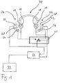
- Fig. 1 is a schematic view of a system for measuring the acoustic attenuation obtained by hearing protection device 10 worn by a user.
- the hearing protection device 10 is a customized earplug 10 comprising a hard shell 12 which may have an elasticity from shore D85 to D65 and may be made of polyamide.
- the earplug 10 is inserted at least in part into the user's ear canal 14 in an attenuation position.
- the shell 12 has an outer surface individually shaped according to the measured shape of the user's outer ear and ear canal.
- the shape of the user's outer ear and ear canal may be determined by direct three-dimensional scanning of the ear canal of the concha or by producing an impression of the ear canal and the concha which subsequently undergoes scanning.
- the digital data obtained by the scanning process is then used to create the hard shell by an additive or incremental layer-by-layer build-up process. Examples of such processes for producing customized earplugs can be found, for example, in US 2003/0133583 A1 or US 6,533,062 B1 .
- the earplug 10 includes a microphone 16 which is oriented towards the user's ear canal 14 and the user's ear drum 19 for capturing sound in the ear canal 14.
- the acoustic connection of the microphone 16 to the ear canal 14 usually will is obtained by providing a corresponding sound passage 18 in the earplug 10, which extends from the microphone 16 to the inner end of the earplug 10.
- the microphone 16 is electrically connected to a means for processing the audio signals captured by the microphone 16 from the sound in the ear canal 14. According to the example shown in Fig. 1 the microphone 16 for this purpose may be connected via an automatic switch 20 and a sound card 22 to a computer 24, for example via a USB interface.
- the system also comprises a cup-like measuring device 26 which is positioned at the user's ear in such a manner that a closed space 28 surrounding the earplug 10 positioned in the ear canal 14 is created by the measuring device 26.
- the measuring device 26 is one cup of a headphone 30.
- the measuring device 26 comprises a loudspeaker 32 which is oriented towards the user's ear for providing test sound to the closed space 28 and a microphone 34 which is oriented towards the user's ear for picking up sound in the closed space 28 in order to capture audio signals from the sound in the closed space 28.
- the microphone 34 is electrically connected via the automatic switch 20 and the sound card 22 to the computer 24, while the loudspeaker 32 is connected via the sound card 22 to the computer 24.
- the system is binaural, i.e. at each ear an earplug 10 and a measuring device 26 are provided.
- the switch 20 serves to switch between an acoustic attenuation measurement for the left ear and the right ear, with the measurement being performed subsequently for the two ears.
- an earplug 10 is inserted into the user's ear canal 14 of his left ear and right ear, respectively. Subsequently, the headphone 30 is positioned at the user's head in such a manner that the closed space 28 is formed within each cup 26 around each earplug 10.
- the microphones 16, the microphones 34 and the loudspeakers 28 are connected to the computer 24 via the sound card 22. Before the actual measurement starts, an audio signal is generated by the computer 24 and the sound card 22 which sets the switch 20, for example, to the right ear position as shown in Fig. 1 .
- a test audio signal is generated by the computer 24 and the sound card 22 and is supplied to the loudspeaker 32 which creates a corresponding test sound in the closed space 28.
- This test sound is directly picked-up by the microphone 34 of the cup 26, and a corresponding audio signal is supplied via the sound card 22 to the computer 24.
- the test sound as attenuated by action of the earplug 10 is picked-up by the microphone 16 of the earplug 10 from the ear canal 14 which is acoustically sealed by the earplug 10, and a corresponding audio signal is supplied via the sound card 22 to the computer 24.
- the audio signals from the microphones 16 and 34 undergo some signal processing, such as recording, Fast Fourier Transformation (FFT) and conversion in octave bands, in the computer 24, and subsequently the acoustic attenuation provided by the earplug 10 can be estimated from the processed audio signals, i.e. from the sound level measured by each of the microphones 16 and 34.
- FFT Fast Fourier Transformation
- an audio signal is generated by the computer 24 and the sound card 22, which acts upon the automatic switch 20 in such a manner that it changes into the position for the left ear measurement. Then the attenuation measurement described above is performed for the left ear.
- the earplug 10 is designed such that the microphone 16 is part of a measurement module 40 which can be detachably connected to the shell 12 for carrying out the attenuation measurement.
- the shell 12 comprises an outer cavity 42 into which the measurement module 40 is to be inserted in a detachable manner.
- the shell 12 is provided with radially movable engagement elements 82 which are radially biased towards the centre of the shell 12 by spring elements 84.
- the engagement elements 82 may be balls.
- the measurement module 40 is provided with a circumferential groove 80 at the outer surface into which the engagement elements 82 may engage.
- the cavity 42 is provided with a sealing lip 34 adapted for engagement with a mating groove 36 at the measurement module 40.
- the shell 12 comprises an acoustic valve 48 at the inner end of the cavity 42, which is formed by a conical valve body 50 which is outwardly biased by a spring 52 in a recess 54 and which is tapered outwardly.
- a conical valve body 50 which is outwardly biased by a spring 52 in a recess 54 and which is tapered outwardly.
- the valve body 50 In the closed position of the valve 48 shown in Fig. 3 the sound passage 18 extending from the cavity 42 to the inner end of the shell 12 is acoustically closed by the valve body 50.
- the valve body 50 is forced inwardly against the biasing force of the spring 52 by an axial extension 44 of the measurement module 40 so that the sound passage 18 is opened for acoustic connection to the microphone 16 of the measurement module.
- the measurement module 40 also may comprises an electronic unit 46 connected to the microphone 16 for performing signal processing of the audio signals provided by the microphone 16, for example, pre-amplification. Finally, the measurement module 40 comprises an electrical connection 56 to the automatic switch 20.
- the measurement module 40 may be removed again from the earplug 10 and may be replaced by a functional module (not shown) which is connected to the shell 12 in a detachable manner similar to the measurement module 40.
- a functional module may include an acoustic filter and/or a wireless communication unit for the actual use of the earplug 10 by the user.
- the mechanism for connecting the measurement module 40 to the earplug 10 in a detachable manner may be any appropriate quickly detachable connection, such as a clipping connection, a screwing connection or a bayonet coupling. Examples of such connections are given in EP 1 674 059 A1 .
- the microphone of the hearing protection device and the microphone of the measuring device are calibrated relative to each other prior to the in-situ attenuation measurement.
- the microphone of the hearing protection device and the microphone of the measuring device are calibrated relative to each other prior to the in-situ attenuation measurement.
- a measurement device 26 of the type shown in Fig. 1 and an earplug 10 of the type shown Fig. 3 such calibration can be effected by the procedure shown in Figs. 4 and 5 .
- the measurement modules 40 with the microphone 16 for the left ear earplug 10 and the right ear earplug 10 are mounted in a mating receptacle 60A and 60B, respectively, of a plate-like holder 62, preferably in such a manner that the microphones 16 are facing opposite sides.
- Each measurement module 40 is connected via the electrical connection 56 in the manner of Fig. 1 via the switch 20 to the sound card 22 and thus to the computer 24.
- the holder 62 with the measurement modules 40 mounted on it is placed between the cups 26 of the measurement headphone 30.
- the cups 26 are manually pressed together so that the holder 62 is sandwiched in-between in a manner that each cup 26 creates a closed space around the respective measurement module 40, i.e. the respective microphone 16.
- an audio signal is generated by the computer 24 and the sound card 22 which sets the switch 20, for example, to the right ear position. Then a test audio signal is generated by the computer 24 and the sound card 22 and is supplied to the loudspeaker 32 which creates a corresponding test sound in the closed space 28. This test sound is directly picked-up by the microphone 34 of the right ear cup 26, and a corresponding audio signal is supplied via the sound card 22 to the computer 24. Simultaneously the test sound is also directly picked-up by the microphone 16 of the measurement module 40 mounted in the receptacle 60A, and a corresponding audio signal is supplied via the sound card 22 to the computer 24.
- the audio signals from the microphones 16 and 34 undergo some signal processing in the computer 24, and subsequently one calibration factor or a set of calibration factors applicable for the microphone 34 of the right ear cup 26 relative to the microphone 16 of the right ear measurement module 40 is determined from the processed audio signals, i.e. from the audio signal level provided by each of the microphones 16 and 34.
- This calibration factor or set of calibration factors is then used as correction for the audio signal levels obtained in the above described right ear attenuation measurement.
- the measurement modules 40 are marked in order to be easily distinguished, for example by a colour code.
- an audio signal is generated by the computer 24 and the sound card 22, which acts upon the automatic switch 20 in such a manner that it changes into the position for the left ear measurement.
- the calibration measurement described above is performed for the left ear cup 26 and the microphone 16 of the measurement module 40 mounted in the receptacle 60B in order to obtain the calibration factor or set of calibration factors for the microphone 34 of the left ear cup 26 and the microphone 16 of the left ear measurement module 40.
Landscapes
- Health & Medical Sciences (AREA)
- General Health & Medical Sciences (AREA)
- Otolaryngology (AREA)
- Life Sciences & Earth Sciences (AREA)
- Physics & Mathematics (AREA)
- Engineering & Computer Science (AREA)
- Acoustics & Sound (AREA)
- Psychology (AREA)
- Animal Behavior & Ethology (AREA)
- Biophysics (AREA)
- Neurosurgery (AREA)
- Biomedical Technology (AREA)
- Heart & Thoracic Surgery (AREA)
- Vascular Medicine (AREA)
- Signal Processing (AREA)
- Public Health (AREA)
- Veterinary Medicine (AREA)
- Measurement Of The Respiration, Hearing Ability, Form, And Blood Characteristics Of Living Organisms (AREA)
- Headphones And Earphones (AREA)
- Measurement Of Mechanical Vibrations Or Ultrasonic Waves (AREA)
- Measurement Of Resistance Or Impedance (AREA)
- Investigating Or Analyzing Materials By The Use Of Ultrasonic Waves (AREA)
- Length Measuring Devices Characterised By Use Of Acoustic Means (AREA)
Abstract
Description
- The present invention relates to a method and a system for measuring in-situ the acoustic attenuation provided by a hearing protection device worn by a user.
-
US 6,687,377 B2 relates to a method for measuring the acoustic attenuation provided by a customized earplug, wherein the earplug is provided with a sound bore extending from the outer side of the earplug to the inner end of the earplug, wherein a remote device is inserted into the outer end of the sound bore, which remote device comprises a first microphone oriented towards the sound bore and a second microphone oriented towards ambience, and wherein test sound is provided by an external loudspeaker. Both the loudspeaker and the remote device are connected to a computer unit on which a measurement program is run. The acoustic attenuation provided by the earplug is calculated from the sound level difference between the first microphone and the second microphone. -
US 5,577,511 relates to a method for measuring in-situ the acoustic attenuation provided by an earplug, wherein a probe tube extends through the earplug into the ear canal and wherein the outer end of the probe tube is connected to a first microphone, while a second microphone is provided at the ear for measuring sound pressure levels exterior to the ear canal as a reference microphone. The acoustic attenuation provided by the earplug is calculated from the difference of the sound levels measured by the first and the second microphone. The test sound for the measurement is the user's voice. -
US 6,567,524 B1 relates to a customized earplug which comprises an inner microphone oriented towards the ear canal, an outer microphone oriented towards ambience and a loudspeaker oriented towards the ear canal. The earplug may be used for online control and verification of the acoustic attenuation provided by the earplug by generating a test sound by the loudspeaker and analyzing the signal picked up by the inner microphone. -
DE 101 17 705 A1 relates to a hearing protection headphone which comprises a microphone oriented towards ambience and into which a hearing protection earplug is integrated which comprises a loudspeaker oriented towards the ear canal and a microphone oriented towards the ear canal for picking up sound in the ear canal for active noise reduction purposes. The microphone of the headphone is used for selectively providing ambient sound to the ear canal via the loudspeaker of the earplug for communication purposes. - It is an object of the invention to provide for a reliable and reproducible method for measuring in-situ the acoustic attenuation provided by a hearing protection device. It is a further object to provide for a corresponding system.
- These objects are achieved by a method as defined in claim 1 and a system as defined in claim 11, respectively.
- The invention is beneficial in that, by providing the hearing protection device with a microphone oriented towards the ear canal and by using a separate cup-like measuring device which creates a closed space surrounding the hearing protection device and which comprises a loudspeaker for providing a test sound to the closed space and a microphone for picking up the level of the test sound in the closed space, particularly reliable and reproducible in-situ measurements of the acoustic attenuation provided by the hearing protection device can be obtained, since well-defined test conditions are provided by the arrangement of the hearing protection device and the measuring device. In addition, by utilizing this concept, the modifications to the hearing protection device required for the in-situ measurement with regard to a standard hearing protection device can be kept low.
- Preferred embodiments of the invention are described in the dependent claims.
- In the following, examples of the invention will be illustrated by reference to the attached drawings, wherein:
- Fig. 1
- shows schematically an example of an in-situ acoustic attenuation measurement system according to the invention;
- Fig. 2
-
Fig. 2 is a more detailed schematic view of one ear of the user during an in-situ acoustic attenuation measurement; - Fig. 3
- is a schematic side view, partially in cross-section, of a hearing protection earplug to be used in the invention;
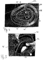
- Fig. 4
- is a top view of a holder used for calibrating the microphones used in an in-situ acoustic attenuation measurement system according to the invention; and
- Fig. 5
- is a view of a headphone and the holder of
Fig. 4 during a calibration measurement according to the invention. -
Fig. 1 is a schematic view of a system for measuring the acoustic attenuation obtained byhearing protection device 10 worn by a user. Preferably, thehearing protection device 10 is a customizedearplug 10 comprising ahard shell 12 which may have an elasticity from shore D85 to D65 and may be made of polyamide. Theearplug 10 is inserted at least in part into the user'sear canal 14 in an attenuation position. In order to achieve optimized fit of theshell 12 within the user's out ear and ear canal, theshell 12 has an outer surface individually shaped according to the measured shape of the user's outer ear and ear canal. The shape of the user's outer ear and ear canal may be determined by direct three-dimensional scanning of the ear canal of the concha or by producing an impression of the ear canal and the concha which subsequently undergoes scanning. The digital data obtained by the scanning process is then used to create the hard shell by an additive or incremental layer-by-layer build-up process. Examples of such processes for producing customized earplugs can be found, for example, inUS 2003/0133583 A1 orUS 6,533,062 B1 . - The
earplug 10 includes amicrophone 16 which is oriented towards the user'sear canal 14 and the user's ear drum 19 for capturing sound in theear canal 14. The acoustic connection of themicrophone 16 to theear canal 14 usually will is obtained by providing acorresponding sound passage 18 in theearplug 10, which extends from themicrophone 16 to the inner end of theearplug 10. - The
microphone 16 is electrically connected to a means for processing the audio signals captured by themicrophone 16 from the sound in theear canal 14. According to the example shown inFig. 1 themicrophone 16 for this purpose may be connected via anautomatic switch 20 and asound card 22 to acomputer 24, for example via a USB interface. - The system also comprises a cup-
like measuring device 26 which is positioned at the user's ear in such a manner that a closedspace 28 surrounding theearplug 10 positioned in theear canal 14 is created by themeasuring device 26. Preferably, as shown inFigs. 1 and2 , themeasuring device 26 is one cup of aheadphone 30. Themeasuring device 26 comprises aloudspeaker 32 which is oriented towards the user's ear for providing test sound to the closedspace 28 and amicrophone 34 which is oriented towards the user's ear for picking up sound in the closedspace 28 in order to capture audio signals from the sound in the closedspace 28. Themicrophone 34 is electrically connected via theautomatic switch 20 and thesound card 22 to thecomputer 24, while theloudspeaker 32 is connected via thesound card 22 to thecomputer 24. - According to
Fig. 1 , the system is binaural, i.e. at each ear anearplug 10 and ameasuring device 26 are provided. Theswitch 20 serves to switch between an acoustic attenuation measurement for the left ear and the right ear, with the measurement being performed subsequently for the two ears. - For carrying-out an in-situ acoustic attenuation measurement first an
earplug 10 is inserted into the user'sear canal 14 of his left ear and right ear, respectively. Subsequently, theheadphone 30 is positioned at the user's head in such a manner that the closedspace 28 is formed within eachcup 26 around eachearplug 10. Themicrophones 16, themicrophones 34 and theloudspeakers 28 are connected to thecomputer 24 via thesound card 22. Before the actual measurement starts, an audio signal is generated by thecomputer 24 and thesound card 22 which sets theswitch 20, for example, to the right ear position as shown inFig. 1 . Then a test audio signal is generated by thecomputer 24 and thesound card 22 and is supplied to theloudspeaker 32 which creates a corresponding test sound in the closedspace 28. This test sound is directly picked-up by themicrophone 34 of thecup 26, and a corresponding audio signal is supplied via thesound card 22 to thecomputer 24. Simultaneously the test sound as attenuated by action of theearplug 10 is picked-up by themicrophone 16 of theearplug 10 from theear canal 14 which is acoustically sealed by theearplug 10, and a corresponding audio signal is supplied via thesound card 22 to thecomputer 24. The audio signals from themicrophones computer 24, and subsequently the acoustic attenuation provided by theearplug 10 can be estimated from the processed audio signals, i.e. from the sound level measured by each of themicrophones - Subsequently an audio signal is generated by the
computer 24 and thesound card 22, which acts upon theautomatic switch 20 in such a manner that it changes into the position for the left ear measurement. Then the attenuation measurement described above is performed for the left ear. - According to a preferred embodiment the
earplug 10 is designed such that themicrophone 16 is part of ameasurement module 40 which can be detachably connected to theshell 12 for carrying out the attenuation measurement. According toFig. 3 theshell 12 comprises an outer cavity 42 into which themeasurement module 40 is to be inserted in a detachable manner. To this end, theshell 12 is provided with radiallymovable engagement elements 82 which are radially biased towards the centre of theshell 12 byspring elements 84. Theengagement elements 82 may be balls. Themeasurement module 40 is provided with acircumferential groove 80 at the outer surface into which theengagement elements 82 may engage. Further, the cavity 42 is provided with asealing lip 34 adapted for engagement with amating groove 36 at themeasurement module 40. - In addition, the
shell 12 comprises an acoustic valve 48 at the inner end of the cavity 42, which is formed by aconical valve body 50 which is outwardly biased by aspring 52 in arecess 54 and which is tapered outwardly. In the closed position of the valve 48 shown inFig. 3 thesound passage 18 extending from the cavity 42 to the inner end of theshell 12 is acoustically closed by thevalve body 50. However, when themeasurement module 40 is inserted into the cavity 42, thevalve body 50 is forced inwardly against the biasing force of thespring 52 by anaxial extension 44 of themeasurement module 40 so that thesound passage 18 is opened for acoustic connection to themicrophone 16 of the measurement module. - The
measurement module 40 also may comprises anelectronic unit 46 connected to themicrophone 16 for performing signal processing of the audio signals provided by themicrophone 16, for example, pre-amplification. Finally, themeasurement module 40 comprises anelectrical connection 56 to theautomatic switch 20. - When the acoustic attenuation measurement has been terminated, the
measurement module 40 may be removed again from theearplug 10 and may be replaced by a functional module (not shown) which is connected to theshell 12 in a detachable manner similar to themeasurement module 40. Such functional module may include an acoustic filter and/or a wireless communication unit for the actual use of theearplug 10 by the user. - The mechanism for connecting the
measurement module 40 to theearplug 10 in a detachable manner may be any appropriate quickly detachable connection, such as a clipping connection, a screwing connection or a bayonet coupling. Examples of such connections are given inEP 1 674 059 A1 . - Preferably, the microphone of the hearing protection device and the microphone of the measuring device are calibrated relative to each other prior to the in-situ attenuation measurement. For example, for a
measurement device 26 of the type shown inFig. 1 and anearplug 10 of the type shownFig. 3 such calibration can be effected by the procedure shown inFigs. 4 and 5 . - In a first step, the
measurement modules 40 with themicrophone 16 for theleft ear earplug 10 and theright ear earplug 10 are mounted in a mating receptacle 60A and 60B, respectively, of a plate-like holder 62, preferably in such a manner that themicrophones 16 are facing opposite sides. Eachmeasurement module 40 is connected via theelectrical connection 56 in the manner ofFig. 1 via theswitch 20 to thesound card 22 and thus to thecomputer 24. - In a second step, the
holder 62 with themeasurement modules 40 mounted on it is placed between thecups 26 of themeasurement headphone 30. Thecups 26 are manually pressed together so that theholder 62 is sandwiched in-between in a manner that eachcup 26 creates a closed space around therespective measurement module 40, i.e. therespective microphone 16. - Before the actual calibration measurement starts, an audio signal is generated by the
computer 24 and thesound card 22 which sets theswitch 20, for example, to the right ear position. Then a test audio signal is generated by thecomputer 24 and thesound card 22 and is supplied to theloudspeaker 32 which creates a corresponding test sound in the closedspace 28. This test sound is directly picked-up by themicrophone 34 of theright ear cup 26, and a corresponding audio signal is supplied via thesound card 22 to thecomputer 24. Simultaneously the test sound is also directly picked-up by themicrophone 16 of themeasurement module 40 mounted in the receptacle 60A, and a corresponding audio signal is supplied via thesound card 22 to thecomputer 24. The audio signals from themicrophones computer 24, and subsequently one calibration factor or a set of calibration factors applicable for themicrophone 34 of theright ear cup 26 relative to themicrophone 16 of the rightear measurement module 40 is determined from the processed audio signals, i.e. from the audio signal level provided by each of themicrophones measurement modules 40 is used in the right ear attenuation measurement, themeasurement modules 40 are marked in order to be easily distinguished, for example by a colour code. - Subsequently an audio signal is generated by the
computer 24 and thesound card 22, which acts upon theautomatic switch 20 in such a manner that it changes into the position for the left ear measurement. Then the calibration measurement described above is performed for theleft ear cup 26 and themicrophone 16 of themeasurement module 40 mounted in the receptacle 60B in order to obtain the calibration factor or set of calibration factors for themicrophone 34 of theleft ear cup 26 and themicrophone 16 of the leftear measurement module 40.
Claims (15)
- A method for measuring the acoustic attenuation obtained by a hearing protection device (10) worn by a user, comprising:positioning the hearing protection device (10) at the user's ear in an attenuation position, said hearing protection device (10) comprising a microphone (16) oriented towards the user's ear canal (14) for capturing sound in the user's ear canal (14);positioning a cup-like measuring device (26) at the user's ear in such a manner that a closed space (28) surrounding the hearing protection device positioned in the attenuation position is created by the measuring device (26), said measuring device (26) comprising a loudspeaker (32) oriented towards to the user's ear for providing sound to said closed space (28) and a microphone (34) oriented towards the user's ear for capturing audio signals from sound in said closed space (28);providing a test signal via the loudspeaker (32), capturing audio signals representative of the level of the test signal in the closed space (28) by the microphone (34) of the measuring device (26) and capturing audio signals representative of the level of the test signal in the user's ear canal (14) by the microphone (16) of the hearing protection device (10);processing the audio signals captured by the microphone (34) of the measuring device (26) and the audio signals captured by the microphone (16) of the hearing protection device (10) and estimating the attenuation provided by the hearing protection device (10) from the processed audio signals.
- The method of claim 1, wherein the processing of the audio signals captured by the microphone (34) of the measuring device (26) and of the audio signals captured by the microphone (16) of the hearing protection device (10) includes Fast Fourier Transformation and conversion in octave bands.
- The method of one of claims 1 and 2, wherein the hearing protection device (10) and the measuring device (26) are connected via an interface to an external device (22, 24) which generates said test signal and processes the audio signals captured by the microphone (34) of the measuring device (26) and the audio signals captured by the microphone of the hearing protection device (10) and estimates the attenuation provided by the hearing protection device (10).
- The method of one of the preceding claims, wherein the hearing protection device is an earplug (10) which is inserted at least in part into the user's ear canal (14), and wherein the earplug (10) comprises a sound passage (18) extending from the microphone (16) to that end of the earplug (10) facing the user's ear drum (19).
- The method of claim 4, wherein the microphone (16) of the earplug (10) is part of a measurement module (40) which is connected to the earplug (10) in a detachable manner prior to the acoustic attenuation measurement and wherein the measurement module (40) is removed from the earplug (10) after the acoustic attenuation measurement.
- The method of claim 5, wherein after the acoustic attenuation measurement the measurement module (40) is replaced by a functional module which is connected to the earplug (10) in a detachable manner.
- The method of claim 6, wherein the functional module includes an acoustic filter and/or a wireless communication unit.
- The method of one of the preceding claims, wherein the method is subsequently applied to both ears of the user.
- The method of one of the preceding claims, wherein prior to measuring the acoustic attenuation the microphone (16) of the hearing protection device (10) and the microphone (34) of the measuring device (26) are calibrated relative to each other by:mounting the microphone (16) of the hearing protection device (10) at a holder (62);positioning the measuring device (26) at the holder (62) in such a manner that a closed space (28) surrounding the microphone (16) of the hearing protection device (10) mounted at the holder (62) is created by the measuring device (26);providing a test signal via the loudspeaker (32), capturing audio signals representative of the level of the test signal in the closed space (28) by the microphone (34) of the measuring device (26) and capturing audio signals representative of the level of the test signal in the closed space by the microphone (16) of the hearing protection device (10); andcomparing the audio signals captured by the microphone (16) of the hearing protection device (10) and the audio signal captured by the microphone (34) of the measuring device (36).
- The method of claim 9, wherein the microphone (16) of the hearing protection device (10) is mounted at the holder (62) separate from the hearing protection device (10) for the calibration measurement and is detachably mounted at the hearing protection device (10) after the calibration measurement has been terminated, wherein the holder (62) has a plate-like shape and wherein the cup-like part of the measuring device is a cup (26) of a headphone (30), which is pressed against the holder (62) for creating said enclosed space (28), and wherein the holder (62) is placed between the two cups (26) of the headphone (30) which are pressed together.
- A system for measuring the acoustic attenuation obtained by a hearing protection device (10) worn by a user, comprising:a hearing protection device (10) capably of being positioned at the user's ear in an attenuation position and comprising a microphone (16) oriented towards the user's ear canal (14), when said hearing protection device is positioned in alternation position, for capturing audio signals from sound in the user's ear canal (14);a cup-like measuring device (26) capable of being positioned at the user's ear in such a manner that a closed space (28) surrounding the hearing protection device (10) positioned in the attenuation position is created by the measuring device (26), said measuring device comprising (26) a loudspeaker (32) oriented towards the user's ear for providing sound to said closed space, (28) and a microphone (34) oriented towards the user's ear for capturing audio signals from sound in said closed space (28);means for providing a test signal via the loudspeaker (32) to said closed space (28); andmeans (22, 24, 46) adapted for processing the audio signals captured by the microphone (34) of the measuring device (26) and the audio signals captured by the microphones (16) of the hearing protection device (10) and adapted for estimating the attenuation provided by the hearing protection device (10) from the processed audio signals.
- The system of claim 11, wherein the hearing protection device (10) and the measuring device (26) comprise an interface (56) for being connected to an external device (22, 24) adapted for generating said test signal and for processing the audio signals captured by the microphone (34) of the measuring device (26) and the audio signals captured by the microphone (16) of the hearing protection device (10) and estimating the attenuation provided by the hearing protection device (10).
- The system of one of the claims 11, and 12, wherein the hearing protection device is an earplug (10) comprising a shell (12) to be inserted into the user's ear canal (14), and wherein the shell (12) comprises a sound passage (18) extending from the microphone (16) to that end of the earplug (10) which is to face the user's ear drum (19).
- The system of claim 13, wherein the microphone (16) of the earplug (10) is part of a measurement module (40) which is detachably connected to the shell (12), and wherein the shell (12) comprises valve means (48, 50, 52) which are moveable, upon connecting the measurement module (40) to the shell (12), from a closed position in which the valve means (48, 50, 52) acoustically closes the sound passage (18) into an open position in which the valve means (48, 50, 52) acoustically opens the sound passage (18), the valve means (48, 50, 52) being biased towards the closed position in order to acoustically close the sound passage (18) when the measurement module (40) is removed from the shell (12), and wherein the microphone (16) is acoustically connected to the sound passage (18) when said measurement module (40) is connected to the shell (12).
- The system of one of claims 11 to 14, wherein the cup-like part of the measuring device is a cup (26) of a headphone (30).
Applications Claiming Priority (1)
| Application Number | Priority Date | Filing Date | Title |
|---|---|---|---|
| PCT/EP2006/006882 WO2008006393A2 (en) | 2006-07-13 | 2006-07-13 | Method for in-situ measuring of acoustic attenuation and system therefor |
Publications (2)
| Publication Number | Publication Date |
|---|---|
| EP2044807A2 EP2044807A2 (en) | 2009-04-08 |
| EP2044807B1 true EP2044807B1 (en) | 2009-09-02 |
Family
ID=38873380
Family Applications (1)
| Application Number | Title | Priority Date | Filing Date |
|---|---|---|---|
| EP06762574A Expired - Lifetime EP2044807B1 (en) | 2006-07-13 | 2006-07-13 | Method for in-situ measuring of acoustic attenuation and system therefor |
Country Status (5)
| Country | Link |
|---|---|
| EP (1) | EP2044807B1 (en) |
| AT (1) | ATE442011T1 (en) |
| DE (1) | DE602006008993D1 (en) |
| DK (1) | DK2044807T3 (en) |
| WO (1) | WO2008006393A2 (en) |
Cited By (1)
| Publication number | Priority date | Publication date | Assignee | Title |
|---|---|---|---|---|
| EP4075830A1 (en) | 2021-04-15 | 2022-10-19 | Sonova AG | System and method for estimating an acoustic attenuation of a hearing protection device |
Families Citing this family (2)
| Publication number | Priority date | Publication date | Assignee | Title |
|---|---|---|---|---|
| FR2937858B1 (en) * | 2009-03-18 | 2011-01-14 | Frederic Louis Christian Devinant | DEVICE AND METHOD FOR PROTECTING AN INDIVIDUAL AGAINST NOISE |
| BR112017005664B1 (en) | 2014-09-19 | 2023-04-04 | 3M Innovative Properties Company | CIRCO-AURICULAR AUDITORY EVALUATION DEVICE AND METHOD FOR EVALUATING THE PERFORMANCE OF A CIRCO-AURICULAR DEVICE |
Family Cites Families (5)
| Publication number | Priority date | Publication date | Assignee | Title |
|---|---|---|---|---|
| US3968334A (en) * | 1974-10-10 | 1976-07-06 | Miguel Padilla | Audiometric method and apparatus for testing the effectiveness of hearing protective devices |
| US4060701A (en) * | 1975-09-15 | 1977-11-29 | Hearing Evaluation & Acoustic Research, Inc. | Method for testing acoustical attenuation of hearing protectors |
| GB2261950A (en) * | 1991-11-28 | 1993-06-02 | Inst Of Occupational Medicine | Assessment of personal hearing protection |
| DE10112305B4 (en) * | 2001-03-14 | 2004-01-08 | Siemens Ag | Hearing protection and method for operating a noise-emitting device |
| ES2832803T3 (en) * | 2003-12-05 | 2021-06-11 | 3M Innovative Properties Co | Method and apparatus for the objective evaluation of the acoustic performance of an in-ear device |
-
2006
- 2006-07-13 EP EP06762574A patent/EP2044807B1/en not_active Expired - Lifetime
- 2006-07-13 DE DE602006008993T patent/DE602006008993D1/en not_active Expired - Lifetime
- 2006-07-13 DK DK06762574T patent/DK2044807T3/en active
- 2006-07-13 WO PCT/EP2006/006882 patent/WO2008006393A2/en not_active Ceased
- 2006-07-13 AT AT06762574T patent/ATE442011T1/en not_active IP Right Cessation
Cited By (1)
| Publication number | Priority date | Publication date | Assignee | Title |
|---|---|---|---|---|
| EP4075830A1 (en) | 2021-04-15 | 2022-10-19 | Sonova AG | System and method for estimating an acoustic attenuation of a hearing protection device |
Also Published As
| Publication number | Publication date |
|---|---|
| EP2044807A2 (en) | 2009-04-08 |
| DE602006008993D1 (en) | 2009-10-15 |
| DK2044807T3 (en) | 2009-11-16 |
| WO2008006393A2 (en) | 2008-01-17 |
| ATE442011T1 (en) | 2009-09-15 |
| WO2008006393A3 (en) | 2008-03-13 |
Similar Documents
| Publication | Publication Date | Title |
|---|---|---|
| US7574917B2 (en) | Method for in-situ measuring of acoustic attenuation and system therefor | |
| EP1708544B1 (en) | System and method for measuring vent effects in a hearing aid | |
| US8712081B2 (en) | Real ear measurement system using thin tube | |
| US9107015B2 (en) | System for automatic fitting using real ear measurement | |
| JP6317025B2 (en) | Measuring apparatus and measuring method | |
| US20040028250A1 (en) | Method of automatically fitting hearing aid | |
| EP2744224A1 (en) | Configurable hearing instrument | |
| US20060188105A1 (en) | In-ear system and method for testing hearing protection | |
| US10582291B2 (en) | Wireless hearing device | |
| US20090238387A1 (en) | Method for actively reducing occlusion comprising plausibility check and corresponding hearing apparatus | |
| EP1631117B1 (en) | Method for obtaining real ear measurements using a hearing aid | |
| US20140037099A1 (en) | Hearing aid with means for estimating the ear plug fitting | |
| US8130992B2 (en) | Hearing aid with anti-feedback | |
| JP2020120372A (en) | Earpiece for hearing device | |
| US20220070596A1 (en) | Device to optically verify custom hearing aid fit and method of use | |
| CN101166374A (en) | Method and device for determining an effective vent of hearing aid | |
| EP2044807A2 (en) | Method for in-situ measuring of acoustic attenuation and system therefor | |
| EP2091267A1 (en) | Receiver module for a hearing device, hearing device and hearing device earpiece | |
| JP4138780B2 (en) | Eustachian tube function test probe | |
| CN1226144A (en) | Ear canal prosthesis for auditory evaluation | |
| US11943586B2 (en) | Method for operating a hearing aid, and hearing aid | |
| EP3739905A1 (en) | Earpiece for the ear canal with off-axis electronic package and receiver | |
| EP4294052A1 (en) | Blank of a housing shell for an earpiece comprising a window in a wall, housing shell, earpiece, and method of its production | |
| CA2497710A1 (en) | In-ear system and method for testing hearing protection |
Legal Events
| Date | Code | Title | Description |
|---|---|---|---|
| PUAI | Public reference made under article 153(3) epc to a published international application that has entered the european phase |
Free format text: ORIGINAL CODE: 0009012 |
|
| 17P | Request for examination filed |
Effective date: 20090204 |
|
| AK | Designated contracting states |
Kind code of ref document: A2 Designated state(s): AT BE BG CH CY CZ DE DK EE ES FI FR GB GR HU IE IS IT LI LT LU LV MC NL PL PT RO SE SI SK TR |
|
| AX | Request for extension of the european patent |
Extension state: AL BA HR MK RS |
|
| GRAP | Despatch of communication of intention to grant a patent |
Free format text: ORIGINAL CODE: EPIDOSNIGR1 |
|
| GRAS | Grant fee paid |
Free format text: ORIGINAL CODE: EPIDOSNIGR3 |
|
| GRAA | (expected) grant |
Free format text: ORIGINAL CODE: 0009210 |
|
| AK | Designated contracting states |
Kind code of ref document: B1 Designated state(s): AT BE BG CH CY CZ DE DK EE ES FI FR GB GR HU IE IS IT LI LT LU LV MC NL PL PT RO SE SI SK TR |
|
| REG | Reference to a national code |
Ref country code: CH Ref legal event code: EP Ref country code: CH Ref legal event code: NV Representative=s name: TROESCH SCHEIDEGGER WERNER AG |
|
| REG | Reference to a national code |
Ref country code: IE Ref legal event code: FG4D |
|
| REF | Corresponds to: |
Ref document number: 602006008993 Country of ref document: DE Date of ref document: 20091015 Kind code of ref document: P |
|
| REG | Reference to a national code |
Ref country code: DK Ref legal event code: T3 |
|
| PG25 | Lapsed in a contracting state [announced via postgrant information from national office to epo] |
Ref country code: LT Free format text: LAPSE BECAUSE OF FAILURE TO SUBMIT A TRANSLATION OF THE DESCRIPTION OR TO PAY THE FEE WITHIN THE PRESCRIBED TIME-LIMIT Effective date: 20090902 Ref country code: SE Free format text: LAPSE BECAUSE OF FAILURE TO SUBMIT A TRANSLATION OF THE DESCRIPTION OR TO PAY THE FEE WITHIN THE PRESCRIBED TIME-LIMIT Effective date: 20090902 Ref country code: FI Free format text: LAPSE BECAUSE OF FAILURE TO SUBMIT A TRANSLATION OF THE DESCRIPTION OR TO PAY THE FEE WITHIN THE PRESCRIBED TIME-LIMIT Effective date: 20090902 |
|
| NLV1 | Nl: lapsed or annulled due to failure to fulfill the requirements of art. 29p and 29m of the patents act | ||
| LTIE | Lt: invalidation of european patent or patent extension |
Effective date: 20090902 |
|
| PG25 | Lapsed in a contracting state [announced via postgrant information from national office to epo] |
Ref country code: NL Free format text: LAPSE BECAUSE OF FAILURE TO SUBMIT A TRANSLATION OF THE DESCRIPTION OR TO PAY THE FEE WITHIN THE PRESCRIBED TIME-LIMIT Effective date: 20090902 Ref country code: SI Free format text: LAPSE BECAUSE OF FAILURE TO SUBMIT A TRANSLATION OF THE DESCRIPTION OR TO PAY THE FEE WITHIN THE PRESCRIBED TIME-LIMIT Effective date: 20090902 Ref country code: PL Free format text: LAPSE BECAUSE OF FAILURE TO SUBMIT A TRANSLATION OF THE DESCRIPTION OR TO PAY THE FEE WITHIN THE PRESCRIBED TIME-LIMIT Effective date: 20090902 Ref country code: LV Free format text: LAPSE BECAUSE OF FAILURE TO SUBMIT A TRANSLATION OF THE DESCRIPTION OR TO PAY THE FEE WITHIN THE PRESCRIBED TIME-LIMIT Effective date: 20090902 |
|
| PG25 | Lapsed in a contracting state [announced via postgrant information from national office to epo] |
Ref country code: CY Free format text: LAPSE BECAUSE OF FAILURE TO SUBMIT A TRANSLATION OF THE DESCRIPTION OR TO PAY THE FEE WITHIN THE PRESCRIBED TIME-LIMIT Effective date: 20090902 |
|
| PG25 | Lapsed in a contracting state [announced via postgrant information from national office to epo] |
Ref country code: RO Free format text: LAPSE BECAUSE OF FAILURE TO SUBMIT A TRANSLATION OF THE DESCRIPTION OR TO PAY THE FEE WITHIN THE PRESCRIBED TIME-LIMIT Effective date: 20090902 Ref country code: PT Free format text: LAPSE BECAUSE OF FAILURE TO SUBMIT A TRANSLATION OF THE DESCRIPTION OR TO PAY THE FEE WITHIN THE PRESCRIBED TIME-LIMIT Effective date: 20100104 Ref country code: IS Free format text: LAPSE BECAUSE OF FAILURE TO SUBMIT A TRANSLATION OF THE DESCRIPTION OR TO PAY THE FEE WITHIN THE PRESCRIBED TIME-LIMIT Effective date: 20100102 Ref country code: ES Free format text: LAPSE BECAUSE OF FAILURE TO SUBMIT A TRANSLATION OF THE DESCRIPTION OR TO PAY THE FEE WITHIN THE PRESCRIBED TIME-LIMIT Effective date: 20091213 Ref country code: CZ Free format text: LAPSE BECAUSE OF FAILURE TO SUBMIT A TRANSLATION OF THE DESCRIPTION OR TO PAY THE FEE WITHIN THE PRESCRIBED TIME-LIMIT Effective date: 20090902 Ref country code: EE Free format text: LAPSE BECAUSE OF FAILURE TO SUBMIT A TRANSLATION OF THE DESCRIPTION OR TO PAY THE FEE WITHIN THE PRESCRIBED TIME-LIMIT Effective date: 20090902 |
|
| PG25 | Lapsed in a contracting state [announced via postgrant information from national office to epo] |
Ref country code: SK Free format text: LAPSE BECAUSE OF FAILURE TO SUBMIT A TRANSLATION OF THE DESCRIPTION OR TO PAY THE FEE WITHIN THE PRESCRIBED TIME-LIMIT Effective date: 20090902 |
|
| PG25 | Lapsed in a contracting state [announced via postgrant information from national office to epo] |
Ref country code: AT Free format text: LAPSE BECAUSE OF FAILURE TO SUBMIT A TRANSLATION OF THE DESCRIPTION OR TO PAY THE FEE WITHIN THE PRESCRIBED TIME-LIMIT Effective date: 20090902 Ref country code: BE Free format text: LAPSE BECAUSE OF FAILURE TO SUBMIT A TRANSLATION OF THE DESCRIPTION OR TO PAY THE FEE WITHIN THE PRESCRIBED TIME-LIMIT Effective date: 20090902 |
|
| PLBE | No opposition filed within time limit |
Free format text: ORIGINAL CODE: 0009261 |
|
| STAA | Information on the status of an ep patent application or granted ep patent |
Free format text: STATUS: NO OPPOSITION FILED WITHIN TIME LIMIT |
|
| 26N | No opposition filed |
Effective date: 20100603 |
|
| PG25 | Lapsed in a contracting state [announced via postgrant information from national office to epo] |
Ref country code: GR Free format text: LAPSE BECAUSE OF FAILURE TO SUBMIT A TRANSLATION OF THE DESCRIPTION OR TO PAY THE FEE WITHIN THE PRESCRIBED TIME-LIMIT Effective date: 20091203 |
|
| PG25 | Lapsed in a contracting state [announced via postgrant information from national office to epo] |
Ref country code: MC Free format text: LAPSE BECAUSE OF NON-PAYMENT OF DUE FEES Effective date: 20100731 |
|
| PG25 | Lapsed in a contracting state [announced via postgrant information from national office to epo] |
Ref country code: IT Free format text: LAPSE BECAUSE OF FAILURE TO SUBMIT A TRANSLATION OF THE DESCRIPTION OR TO PAY THE FEE WITHIN THE PRESCRIBED TIME-LIMIT Effective date: 20090902 |
|
| PG25 | Lapsed in a contracting state [announced via postgrant information from national office to epo] |
Ref country code: IE Free format text: LAPSE BECAUSE OF NON-PAYMENT OF DUE FEES Effective date: 20100713 |
|
| PG25 | Lapsed in a contracting state [announced via postgrant information from national office to epo] |
Ref country code: HU Free format text: LAPSE BECAUSE OF FAILURE TO SUBMIT A TRANSLATION OF THE DESCRIPTION OR TO PAY THE FEE WITHIN THE PRESCRIBED TIME-LIMIT Effective date: 20100303 Ref country code: BG Free format text: LAPSE BECAUSE OF FAILURE TO SUBMIT A TRANSLATION OF THE DESCRIPTION OR TO PAY THE FEE WITHIN THE PRESCRIBED TIME-LIMIT Effective date: 20090902 Ref country code: LU Free format text: LAPSE BECAUSE OF NON-PAYMENT OF DUE FEES Effective date: 20100713 |
|
| PG25 | Lapsed in a contracting state [announced via postgrant information from national office to epo] |
Ref country code: TR Free format text: LAPSE BECAUSE OF FAILURE TO SUBMIT A TRANSLATION OF THE DESCRIPTION OR TO PAY THE FEE WITHIN THE PRESCRIBED TIME-LIMIT Effective date: 20090902 |
|
| REG | Reference to a national code |
Ref country code: FR Ref legal event code: PLFP Year of fee payment: 11 |
|
| REG | Reference to a national code |
Ref country code: FR Ref legal event code: PLFP Year of fee payment: 12 |
|
| REG | Reference to a national code |
Ref country code: FR Ref legal event code: PLFP Year of fee payment: 13 |
|
| REG | Reference to a national code |
Ref country code: DE Ref legal event code: R084 Ref document number: 602006008993 Country of ref document: DE |
|
| PGFP | Annual fee paid to national office [announced via postgrant information from national office to epo] |
Ref country code: DK Payment date: 20210728 Year of fee payment: 16 Ref country code: CH Payment date: 20210804 Year of fee payment: 16 |
|
| REG | Reference to a national code |
Ref country code: DK Ref legal event code: EBP Effective date: 20220731 |
|
| REG | Reference to a national code |
Ref country code: CH Ref legal event code: PL |
|
| PG25 | Lapsed in a contracting state [announced via postgrant information from national office to epo] |
Ref country code: LI Free format text: LAPSE BECAUSE OF NON-PAYMENT OF DUE FEES Effective date: 20220731 Ref country code: CH Free format text: LAPSE BECAUSE OF NON-PAYMENT OF DUE FEES Effective date: 20220731 |
|
| PG25 | Lapsed in a contracting state [announced via postgrant information from national office to epo] |
Ref country code: DK Free format text: LAPSE BECAUSE OF NON-PAYMENT OF DUE FEES Effective date: 20220731 |
|
| PGFP | Annual fee paid to national office [announced via postgrant information from national office to epo] |
Ref country code: DE Payment date: 20250729 Year of fee payment: 20 |
|
| PGFP | Annual fee paid to national office [announced via postgrant information from national office to epo] |
Ref country code: GB Payment date: 20250728 Year of fee payment: 20 |
|
| PGFP | Annual fee paid to national office [announced via postgrant information from national office to epo] |
Ref country code: FR Payment date: 20250725 Year of fee payment: 20 |
|
| REG | Reference to a national code |
Ref country code: DE Ref legal event code: R071 Ref document number: 602006008993 Country of ref document: DE |
|
| REG | Reference to a national code |
Ref country code: GB Ref legal event code: PE20 Expiry date: 20260712 |