EP2043419A1 - Poste d'intervention sur cartes électroniques à ergonomie améliorée - Google Patents
Poste d'intervention sur cartes électroniques à ergonomie améliorée Download PDFInfo
- Publication number
- EP2043419A1 EP2043419A1 EP08164420A EP08164420A EP2043419A1 EP 2043419 A1 EP2043419 A1 EP 2043419A1 EP 08164420 A EP08164420 A EP 08164420A EP 08164420 A EP08164420 A EP 08164420A EP 2043419 A1 EP2043419 A1 EP 2043419A1
- Authority
- EP
- European Patent Office
- Prior art keywords
- module
- intervention device
- electronic board
- heating module
- card
- Prior art date
- Legal status (The legal status is an assumption and is not a legal conclusion. Google has not performed a legal analysis and makes no representation as to the accuracy of the status listed.)
- Granted
Links
Images


Classifications
-
- H—ELECTRICITY
- H05—ELECTRIC TECHNIQUES NOT OTHERWISE PROVIDED FOR
- H05K—PRINTED CIRCUITS; CASINGS OR CONSTRUCTIONAL DETAILS OF ELECTRIC APPARATUS; MANUFACTURE OF ASSEMBLAGES OF ELECTRICAL COMPONENTS
- H05K3/00—Apparatus or processes for manufacturing printed circuits
- H05K3/30—Assembling printed circuits with electric components, e.g. with resistors
- H05K3/32—Assembling printed circuits with electric components, e.g. with resistors electrically connecting electric components or wires to printed circuits
- H05K3/34—Assembling printed circuits with electric components, e.g. with resistors electrically connecting electric components or wires to printed circuits by soldering
- H05K3/3494—Heating processes for reflow soldering
-
- H—ELECTRICITY
- H05—ELECTRIC TECHNIQUES NOT OTHERWISE PROVIDED FOR
- H05K—PRINTED CIRCUITS; CASINGS OR CONSTRUCTIONAL DETAILS OF ELECTRIC APPARATUS; MANUFACTURE OF ASSEMBLAGES OF ELECTRICAL COMPONENTS
- H05K2203/00—Indexing scheme relating to apparatus or processes for manufacturing printed circuits covered by H05K3/00
- H05K2203/08—Treatments involving gases
- H05K2203/082—Suction, e.g. for holding solder balls or components
-
- H—ELECTRICITY
- H05—ELECTRIC TECHNIQUES NOT OTHERWISE PROVIDED FOR
- H05K—PRINTED CIRCUITS; CASINGS OR CONSTRUCTIONAL DETAILS OF ELECTRIC APPARATUS; MANUFACTURE OF ASSEMBLAGES OF ELECTRICAL COMPONENTS
- H05K2203/00—Indexing scheme relating to apparatus or processes for manufacturing printed circuits covered by H05K3/00
- H05K2203/15—Position of the PCB during processing
- H05K2203/1581—Treating the backside of the PCB, e.g. for heating during soldering or providing a liquid coating on the backside
-
- H—ELECTRICITY
- H05—ELECTRIC TECHNIQUES NOT OTHERWISE PROVIDED FOR
- H05K—PRINTED CIRCUITS; CASINGS OR CONSTRUCTIONAL DETAILS OF ELECTRIC APPARATUS; MANUFACTURE OF ASSEMBLAGES OF ELECTRICAL COMPONENTS
- H05K3/00—Apparatus or processes for manufacturing printed circuits
- H05K3/22—Secondary treatment of printed circuits
- H05K3/225—Correcting or repairing of printed circuits
Definitions
- the present invention applies to workstations for operators having to work on components implanted on electronic boards. Often, these interventions must take place in an environment where the temperature of the components is maintained at a high level, of the order of 100 ° C, during the duration of the intervention. Indeed, temperature variations during the intervention where welding is normally necessary induce stress in the components which may degrade their performance and reliability. This results in both risks and high discomfort for the operators practicing these interventions.
- the discomfort is also due to the fact that the operations are generally performed under binocular control and that the heating device generally used to maintain the temperature of the components will be inserted between the worktop and the plane of the binocular, which means raises the operator's eye placement point on the binocular of more than 10 cm, requiring a standing position or even prohibiting this type of post to operators too small.
- the applicant therefore set out to solve this problem by designing a new intervention device on an electronic card comprising a work plan, a heating module of said card, a visualization optics and a smoke extraction module characterized in that the support and heating module has an upper face which can assume a substantially coplanar position of the working plane serving as a support for said card.
- the heating module of the electronic card intervention device of the invention uses infrared radiation.
- the electronic card intervention device of the invention further comprises a heat evacuation module produced by the convection heating module and suction by the lower face of the work plane towards separate servitudes of the room of the intervention device.
- the heat dissipation module of the electronic card intervention device of the invention comprises baffles distribution of the hot air sucked.
- the heat dissipation module of the electronic card intervention device of the invention which includes baffles distribution of the hot air sucked is able to be put in depression.
- the fume extraction module of the electronic card intervention device of the invention is not easily separable from the viewing optics.
- the work plan of the electronic card intervention device of the invention has an "L" shape, the heating module being positioned substantially at the "L" angle.
- the electronic card intervention device of the invention further comprises a control module to limit the use to authorized persons.
- the integration of the heating module in the worktop allows the evacuation of heat to the outside of the workspace and thus to preserve the operator. It also allows the removal of the elevation and therefore the work in a sitting position.
- This device also has the advantage of allowing easy replacement of the support module. It is therefore more versatile than the devices of the prior art.
- an electronic circuit intervention device normally comprises a support and heating module 110 which is placed on a work plane 130 and comprises an upper surface on which the card on which the operator intervene.
- the thickness of this module 110 is generally of the order of 12 cm. It includes a heating plate whose temperature can reach 330 ° C.
- the workstation also comprises a binocular device 140 whose glasses are raised from the height of the module 110. The heat generated by the hotplate is disengaged in the work space.
- the device is generally associated with an air sleeve which achieves suction welding fumes but it reduces the ambient heat that very limited or even zero.
- the device according to the invention comprises a support and heating module of which only the upper face 220 is apparent and is substantially coplanar with the work plane 230. It can be seen in the figure that the binocular 240 may be in a substantially lower position than the binocular 150 of the figure 1 .
- the heating module itself is located below the worktop. As illustrated on the figure 3 , which is a view from below of the worktop 210, this heating module can be advantageously packaged in a tank 310 of stainless steel or other heat-dissipating material. Suction hoses of flexible material are connected to the tank and drive the sucked air to the easements located in the immediate vicinity of the work plan. The heat dissipation in the upper part of the worktop is greatly reduced.
- the temperature rise in the vicinity of the binocular is commonly 20 to 25 ° C, an ambient temperature can easily reach 45 to 50 ° C. In the device according to the invention, the temperature rise residual is only 2 ° C.
- This tank 310 also has the advantage of preserving the operator accidental leakage of solvent fluid possibly ignited. Under the surface of the worktop 210 there will be provided heat suction nozzles. The surface of the working plane in the vicinity of this support surface will advantageously be covered with a thermally insulating material of the PET type. In addition, it will advantageously be provided inside the tank 310 with internal baffles which reduce the noise according to the principle of the automobile exhaust pipe. Advantageously, the suction of the hot air will be favored by a depression of the tray.
- the support module can be replaced by a full interface allowing the work without use of the heating system.
- the station can be used for interventions on cards that require the use of a binocular but do not require heating.
- the surface 220 is replaced by a different surface.
- the suction module on the upper part of the working space of the prior art 150 is advantageously replaced in one embodiment of the invention by a module 450 comprising one or more nozzles for collecting flue gases, said fumes being also conveyed to the service area by flexible suction hoses.
- the station comprises means for operating by mechanical or electronic key, accessible only to authorized operators. It must also provide an emergency stop means, such as a button to press.
Landscapes
- Engineering & Computer Science (AREA)
- Manufacturing & Machinery (AREA)
- Microelectronics & Electronic Packaging (AREA)
- Cooling Or The Like Of Electrical Apparatus (AREA)
- Thermotherapy And Cooling Therapy Devices (AREA)
Abstract
Description
- La présente invention s'applique aux postes de travail pour des opérateurs ayant à intervenir sur des composants implantés sur des cartes électroniques. Souvent, ces interventions doivent se dérouler dans un environnement où la température des composants est maintenue à un niveau élevé, de l'ordre de 100°C, pendant la durée de l'intervention. En effet, les variations de température en cours d'intervention où un soudage est normalement nécessaire induisent un stress dans les composants qui risque de dégrader leurs performances et fiabilité. Il en résulte à la fois des risques et un inconfort élevé pour les opérateurs pratiquant ces interventions. L'inconfort est aussi lié au fait que les interventions se déroulent généralement sous contrôle par binoculaire et que le dispositif de chauffage généralement utilisé pour maintenir la température des composants va s'intercaler entre le plan de travail et le plan de la binoculaire, ce qui élève le point de pose des yeux de l'opérateurs sur la binoculaire de plus de 10 cm, nécessitant une position debout ou, même interdisant ce type de poste à des opérateurs de taille trop petite.
- Le demandeur s'est donc attaché à résoudre ce problème en concevant un nouveau dispositif d'intervention sur carte électronique comprenant un plan de travail, un module de de chauffage de ladite carte, une optique de visualisation et un module d'aspiration des fumées caractérisé en ce que le module de support et de chauffage a une face supérieure qui peut prendre une position sensiblement coplanaire du plan de travail servant de support à la dite carte.
- Avantageusement, le module de chauffage du dispositif d'intervention sur carte électronique de l'invention utilise un rayonnement infrarouge.
- Avantageusement, le dispositif d'intervention sur carte électronique de l'invention comprend en outre un module d'évacuation de la chaleur produite par le module de chauffage par convection et aspiration par la face inférieure du plan de travail vers des servitudes séparées du local du dispositif d'intervention.
- Avantageusement, le module d'évacuation de la chaleur du dispositif d'intervention sur carte électronique de l'invention comprend des chicanes de répartition de l'air chaud aspiré.
- Avantageusement, le module d'évacuation de la chaleur du dispositif d'intervention sur carte électronique de l'invention qui comprend des chicanes de répartition de l'air chaud aspiré est apte à être mis en dépression.
- Avantageusement, le module d'aspiration des fumées du dispositif d'intervention sur carte électronique de l'invention n'est pas facilement séparable de l'optique de visualisation.
- Avantageusement, le module d'aspiration des fumées du dispositif d'intervention sur carte électronique de l'invention qui n'est pas facilement séparable de l'optique de visualisation comprend des buses mécaniquement liées à l'optique de visualisation et proches de l'objectif de ladite optique.
- Avantageusement, le plan de travail du dispositif d'intervention sur carte électronique de l'invention a une forme en « L », le module de chauffage étant positionné sensiblement à l'angle du « L ».
- Avantageusement, le dispositif d'intervention sur carte électronique de l'invention comprend en outre un module de contrôle pour limiter l'utilisation aux personnes autorisées.
- L'intégration du module de chauffage dans le plan de travail permet de réaliser l'évacuation de la chaleur vers l'extérieur de l'espace de travail et donc d'en préserver l'opérateur. Elle permet également la suppression de l'élévation et donc le travail en position assise.
- Ce dispositif présente en outre l'avantage d'autoriser un remplacement facile du module de support. Il est donc plus versatile que les dispositifs de l'art antérieur.
- L'invention sera mieux comprise et ses différentes caractéristiques et avantages ressortiront de la description qui suit de plusieurs exemples de réalisation et de ses figures annexées dont :
- La
figure 1 représente un dispositif de l'art antérieur; - La
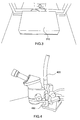
figure 2 représente un dispositif selon l'invention; - La
figure 3 représente un module de support et de chauffage à caissons de répartition de chaleur (vue de dessous le plan de travail); - La
figure 4 représente le module d'aspiration de fumées dans un mode de réalisation du dispositif selon l'invention ; - La
figure 5 représente l'agencement du plan et de l'espace de travail dans un mode de réalisation du dispositif selon l'invention. - Comme illustré sur la
figure 1 , un dispositif d'intervention sur cartes électroniques selon l'art antérieur comprend normalement un module de support et de chauffage 110 qui est posé sur un plan de travail 130 et comporte une surface supérieure sur laquelle est posée la carte sur laquelle l'opérateur doit intervenir. L'épaisseur de ce module 110 est généralement de l'ordre de 12 cm. Il comprend une plaque de chauffage dont la température peut atteindre 330°C. Le poste de travail comprend par ailleurs un dispositif binoculaire 140 dont les lunettes sont surélevées de la hauteur du module 110. La chaleur dégagée par la plaque chauffante est dégagée dans l'espace de travail. On adjoint généralement au dispositif une manche à air qui réalise une aspiration des fumées de soudure mais celle-ci ne réduit la chaleur ambiante que de manière très limitée voir nulle. - Comme on le voit sur la
figure 2 , le dispositif selon l'invention comporte un module de support et de chauffage dont seule la face supérieure 220 est apparente et est sensiblement coplanaire du plan de travail 230. On voit sur la figure que la binoculaire 240 peut être en position sensiblement plus basse que la binoculaire 150 de lafigure 1 . - Le module de chauffage lui-même se situe en dessous du plan de travail. Comme illustré sur la
figure 3 , qui est une vue par le dessous du plan de travail 210, ce module de chauffage peut être avantageusement conditionné dans un bac 310 en acier inoxydable ou dans un autre matériau dissipant la chaleur. Des tuyaux d'aspiration en matière souple sont connectés au bac et conduisent l'air aspiré vers les servitudes situées dans le voisinage immédiat du plan de travail. La dissipation de chaleur dans la partie supérieure du plan de travail est donc grandement réduite. Dans les dispositifs de l'art antérieur, l'élévation de température au voisinage du binoculaire est couramment de 20 à 25°C, soit une température ambiante pouvant facilement atteindre 45 à 50°C. Dans le dispositif selon l'invention, l'élévation de température résiduelle n'est que de 2°C. Ce bac 310 présente en outre l'avantage de préserver l'opérateur des fuites accidentelles de fluide solvant éventuellement enflammé. On prévoira sous la surface du plan de travail 210 des buses d'aspiration de la chaleur. La surface du plan de travail au voisinage de cette surface de support sera avantageusement recouverte d'un matériau thermiquement isolant du type PET. On prévoira en outre avantageusement à l'intérieur du bac 310 des chicanes internes qui réduisent les bruits selon le principe du pot d'échappement automobile. Avantageusement, l'aspiration de l'air chaud sera favorisés par une mise en dépression du bac. - On notera que, dans une variante, le module support peut être remplacé par un interface plein permettant le travail sans utilisation du système de chauffage. Ainsi, le poste peut être utilisé pour des interventions sur cartes qui requièrent l'utilisation d'une binoculaire mais qui ne nécessitent pas le chauffage. Pour cette utilisation, on remplace la surface 220 par une surface différente. Dans ce cas, on prévoira avantageusement un dispositif de sécurité par coupure d'alimentation électrique du chauffage infrarouge lorsque le poste est dans cette configuration sans chauffage (surface supérieure 210 retirée).
- Comme on le voit sur la
figure 4 , le module d'aspiration sur la partie supérieure de l'espace de travail de l'art antérieur 150 est avantageusement remplacé dans un mode de réalisation de l'invention par un module 450 comprenant une ou plusieurs buses de captage des fumées de flux, lesdites fumées étant acheminées également vers l'espace de servitude par des tuyaux souples d'aspiration. - Comme illustré sur la
figure 5 , on prévoira avantageusement un plan de travail en L, la zone de travail de l'opérateur 510 étant située sensiblement dans la partie intérieure de l'angle du L. Les servitudes, tel l'aspirateur, seront préférentiellement situées dans des zones 550 et 560 (inaccessible). Les modules d'extraction de la chaleur et des fumées doivent être connectées vers des recycleurs périphériques situés dans des locaux techniques En fonction de la qualité de l'ergonomie recherchée, on pourra pré-affecter des zones du plan de travail à certaines utilisations, par exemple une zone 520 à du stockage récurrent (fer à souder notamment), une zone 530 au stockage des consommables (soudure, solvants, etc...), une zone 540 à du stockage aléatoire (gaine, fils...). Bien entendu, ces configurations ne sont citées qu'à titre d'exemple de réalisation. Les postes de par leur conception sont naturellement adaptés aux gauchers et aux droitiers. - Le poste comporte un moyen de mise en fonctionnement par clé mécanique ou électronique, accessible uniquement aux opérateurs habilités. Il faut prévoir également un moyen d'arrêt d'urgence, tel qu'un bouton à presser.
- Les exemples de réalisation ci-dessus ne sont bien entendu pas limitatifs et d'autres configurations sont possibles sans sortir du champ de la présente invention.
Claims (9)
- Dispositif d'intervention sur carte électronique comprenant un plan de travail (230), un module de chauffage de ladite carte, ayant une face supérieure (210) sensiblement coplanaire du plan de travail (230) servant de support à la dite carte, caractérisé en ce qu'il comprend en outre un module (310) d'évacuation de la chaleur produite par le module de chauffage par convection et aspiration par la face inférieure du plan de travail (230) vers des servitudes séparées du local du dispositif d'intervention.
- Dispositif d'intervention sur carte électronique selon la revendication 1 caractérisé en ce que module de chauffage utilise un rayonnement infrarouge.
- Dispositif d'intervention sur carte électronique selon la revendication 1 caractérisé en ce que le module d'évacuation de la chaleur (310) comprend des chicanes de répartition de l'air chaud aspiré.
- Dispositif d'intervention sur carte électronique selon la revendication 3 caractérisé en ce que le module d'évacuation de la chaleur (310) est apte à être mis en dépression.
- Dispositif d'intervention sur carte électronique selon la revendication 1 caractérisé en ce qu'il comprend en outre une optique de visualisation (240) et un module d'aspiration des fumées (450).
- Dispositif d'intervention sur carte électronique selon la revendication 5 caractérisé en ce que le module d'aspiration des fumées (450) n'est pas facilement séparable de l'optique de visualisation.
- Dispositif d'intervention sur carte électronique selon la revendication 6 caractérisé en ce que le module d'aspiration des fumées (450) comprend des buses mécaniquement liées à l'optique de visualisation au niveau de l'objectif de ladite optique.
- Dispositif d'intervention sur carte électronique selon la revendication 1 caractérisé en ce que le plan de travail a une forme en « L », le module de chauffage étant positionné sensiblement à l'angle du « L ».
- Dispositif d'intervention sur carte électronique selon la revendication 1 caractérisé en ce qu'il comprend en outre un module de contrôle pour limiter l'utilisation aux personnes autorisées.
Applications Claiming Priority (1)
| Application Number | Priority Date | Filing Date | Title |
|---|---|---|---|
| FR0706843A FR2921789B1 (fr) | 2007-09-28 | 2007-09-28 | Poste d'intervention sur cartes electroniques a ergonomie amelioree |
Publications (2)
| Publication Number | Publication Date |
|---|---|
| EP2043419A1 true EP2043419A1 (fr) | 2009-04-01 |
| EP2043419B1 EP2043419B1 (fr) | 2012-06-20 |
Family
ID=39322799
Family Applications (1)
| Application Number | Title | Priority Date | Filing Date |
|---|---|---|---|
| EP20080164420 Not-in-force EP2043419B1 (fr) | 2007-09-28 | 2008-09-16 | Poste d'intervention sur cartes électroniques à ergonomie améliorée |
Country Status (2)
| Country | Link |
|---|---|
| EP (1) | EP2043419B1 (fr) |
| FR (1) | FR2921789B1 (fr) |
Cited By (1)
| Publication number | Priority date | Publication date | Assignee | Title |
|---|---|---|---|---|
| CN111230393A (zh) * | 2019-07-09 | 2020-06-05 | 杭州顺达伯耐特电梯有限公司 | 导轨支架焊接工装 |
Citations (5)
| Publication number | Priority date | Publication date | Assignee | Title |
|---|---|---|---|---|
| DE2751856A1 (de) * | 1977-11-21 | 1979-05-23 | Fritz Hans Ulrich Dipl Ing | Bestueckungsanordnung |
| GB2063135A (en) * | 1979-11-05 | 1981-06-03 | Blacklock J W | Soldering and desoldering apparatus |
| FR2613174A1 (fr) * | 1987-01-07 | 1988-09-30 | Kontakt Systeme Inter Ag | Plate-forme de travail destinee aux operations consistant a monter en surface des composants sur des plaquettes ou cartes de circuits imprimes |
| US4817851A (en) * | 1986-02-13 | 1989-04-04 | Digital Equipment Corporation | Surface mount technology repair station and method for repair of surface mount technology circuit boards |
| GB2259039A (en) * | 1991-09-02 | 1993-03-03 | Pdr Microelectronics Limited | Directed infra-red rework station |
-
2007
- 2007-09-28 FR FR0706843A patent/FR2921789B1/fr not_active Expired - Fee Related
-
2008
- 2008-09-16 EP EP20080164420 patent/EP2043419B1/fr not_active Not-in-force
Patent Citations (5)
| Publication number | Priority date | Publication date | Assignee | Title |
|---|---|---|---|---|
| DE2751856A1 (de) * | 1977-11-21 | 1979-05-23 | Fritz Hans Ulrich Dipl Ing | Bestueckungsanordnung |
| GB2063135A (en) * | 1979-11-05 | 1981-06-03 | Blacklock J W | Soldering and desoldering apparatus |
| US4817851A (en) * | 1986-02-13 | 1989-04-04 | Digital Equipment Corporation | Surface mount technology repair station and method for repair of surface mount technology circuit boards |
| FR2613174A1 (fr) * | 1987-01-07 | 1988-09-30 | Kontakt Systeme Inter Ag | Plate-forme de travail destinee aux operations consistant a monter en surface des composants sur des plaquettes ou cartes de circuits imprimes |
| GB2259039A (en) * | 1991-09-02 | 1993-03-03 | Pdr Microelectronics Limited | Directed infra-red rework station |
Cited By (2)
| Publication number | Priority date | Publication date | Assignee | Title |
|---|---|---|---|---|
| CN111230393A (zh) * | 2019-07-09 | 2020-06-05 | 杭州顺达伯耐特电梯有限公司 | 导轨支架焊接工装 |
| CN111230393B (zh) * | 2019-07-09 | 2021-08-17 | 杭州顺达伯耐特电梯有限公司 | 导轨支架焊接工装 |
Also Published As
| Publication number | Publication date |
|---|---|
| FR2921789A1 (fr) | 2009-04-03 |
| FR2921789B1 (fr) | 2011-04-01 |
| EP2043419B1 (fr) | 2012-06-20 |
Similar Documents
| Publication | Publication Date | Title |
|---|---|---|
| US12098849B2 (en) | Smokeless grill | |
| EP2234468B1 (fr) | Module électrique | |
| US9410695B2 (en) | Aroma-diffusing heating device | |
| US9500358B2 (en) | Aroma diffusing heating device using an aroma capsule | |
| EP2355643B1 (fr) | Dispositif auxiliaire d'evacuation par conduction de la chaleur produite par une carte elctronique | |
| US20100218959A1 (en) | Method and device for suppression of fire by local flooding with ultra-fine water mist | |
| EP2043419B1 (fr) | Poste d'intervention sur cartes électroniques à ergonomie améliorée | |
| KR102462339B1 (ko) | 내충격성이 강화된 초박막 유리 및 그 제조 방법 | |
| EP3367770A1 (fr) | Module de puissance avec système de refroidissement des cartes électroniques | |
| EP2104139A1 (fr) | Dispositif de préchauffage d'un composant refroidi par conduction et/ou par convection | |
| FR3065787A3 (fr) | Hote d'aspiration pour laboratoire | |
| FR2730040A1 (fr) | Dispositif destine a l'aspiration des fumees de cuisson et a servir de couvercle a la table de cuisson | |
| WO2013175125A2 (fr) | Dispositif de sechage d'au moins un verre optique | |
| FR3000177A1 (fr) | Table de cuisson comprenant un ventilateur et un guide d'air | |
| FR3000178A1 (fr) | Table de cuisson comprenant un moyen de detection de temperature | |
| EP1193452B2 (fr) | Boîtier de commande électronique pour appareils de cuisson | |
| FR3102236A1 (fr) | Dispositif de protection anti-vandalisme pour appareil d’extraction des gaz et des fumées | |
| EP3987986B1 (fr) | Dispositif de cuisson | |
| JPS6115965B2 (fr) | ||
| EP1219902A1 (fr) | Appareil de cuisson | |
| JP5154599B2 (ja) | ガス溶断の集煙装置 | |
| CN102327048A (zh) | 可取出的煨煮区 | |
| FR2609157A1 (fr) | Perfectionnements a des tubes radiants a gaz | |
| FR2913098A1 (fr) | Table de cuisson et procede de surveillance anti-debordement d'un liquide associe | |
| EP4684705A1 (fr) | Appareil de cuisson electrique a air chaud comprenant un recipient de cuisson equipe de parois transparentes |
Legal Events
| Date | Code | Title | Description |
|---|---|---|---|
| PUAI | Public reference made under article 153(3) epc to a published international application that has entered the european phase |
Free format text: ORIGINAL CODE: 0009012 |
|
| AK | Designated contracting states |
Kind code of ref document: A1 Designated state(s): AT BE BG CH CY CZ DE DK EE ES FI FR GB GR HR HU IE IS IT LI LT LU LV MC MT NL NO PL PT RO SE SI SK TR |
|
| AX | Request for extension of the european patent |
Extension state: AL BA MK RS |
|
| 17P | Request for examination filed |
Effective date: 20090925 |
|
| AKX | Designation fees paid |
Designated state(s): AT BE BG CH CY CZ DE DK EE ES FI FR GB GR HR HU IE IS IT LI LT LU LV MC MT NL NO PL PT RO SE SI SK TR |
|
| REG | Reference to a national code |
Ref country code: DE Ref legal event code: R079 Ref document number: 602008016404 Country of ref document: DE Free format text: PREVIOUS MAIN CLASS: H05K0013000000 Ipc: H05K0003340000 |
|
| RIC1 | Information provided on ipc code assigned before grant |
Ipc: H05K 3/34 20060101AFI20111024BHEP |
|
| GRAP | Despatch of communication of intention to grant a patent |
Free format text: ORIGINAL CODE: EPIDOSNIGR1 |
|
| GRAS | Grant fee paid |
Free format text: ORIGINAL CODE: EPIDOSNIGR3 |
|
| GRAA | (expected) grant |
Free format text: ORIGINAL CODE: 0009210 |
|
| AK | Designated contracting states |
Kind code of ref document: B1 Designated state(s): AT BE BG CH CY CZ DE DK EE ES FI FR GB GR HR HU IE IS IT LI LT LU LV MC MT NL NO PL PT RO SE SI SK TR |
|
| REG | Reference to a national code |
Ref country code: GB Ref legal event code: FG4D Free format text: NOT ENGLISH |
|
| REG | Reference to a national code |
Ref country code: CH Ref legal event code: EP |
|
| REG | Reference to a national code |
Ref country code: AT Ref legal event code: REF Ref document number: 563626 Country of ref document: AT Kind code of ref document: T Effective date: 20120715 |
|
| REG | Reference to a national code |
Ref country code: IE Ref legal event code: FG4D Free format text: LANGUAGE OF EP DOCUMENT: FRENCH |
|
| REG | Reference to a national code |
Ref country code: DE Ref legal event code: R096 Ref document number: 602008016404 Country of ref document: DE Effective date: 20120816 |
|
| PG25 | Lapsed in a contracting state [announced via postgrant information from national office to epo] |
Ref country code: FI Free format text: LAPSE BECAUSE OF FAILURE TO SUBMIT A TRANSLATION OF THE DESCRIPTION OR TO PAY THE FEE WITHIN THE PRESCRIBED TIME-LIMIT Effective date: 20120620 Ref country code: NO Free format text: LAPSE BECAUSE OF FAILURE TO SUBMIT A TRANSLATION OF THE DESCRIPTION OR TO PAY THE FEE WITHIN THE PRESCRIBED TIME-LIMIT Effective date: 20120920 Ref country code: SE Free format text: LAPSE BECAUSE OF FAILURE TO SUBMIT A TRANSLATION OF THE DESCRIPTION OR TO PAY THE FEE WITHIN THE PRESCRIBED TIME-LIMIT Effective date: 20120620 Ref country code: LT Free format text: LAPSE BECAUSE OF FAILURE TO SUBMIT A TRANSLATION OF THE DESCRIPTION OR TO PAY THE FEE WITHIN THE PRESCRIBED TIME-LIMIT Effective date: 20120620 |
|
| REG | Reference to a national code |
Ref country code: NL Ref legal event code: VDEP Effective date: 20120620 |
|
| REG | Reference to a national code |
Ref country code: AT Ref legal event code: MK05 Ref document number: 563626 Country of ref document: AT Kind code of ref document: T Effective date: 20120620 |
|
| REG | Reference to a national code |
Ref country code: LT Ref legal event code: MG4D Effective date: 20120620 |
|
| PG25 | Lapsed in a contracting state [announced via postgrant information from national office to epo] |
Ref country code: SI Free format text: LAPSE BECAUSE OF FAILURE TO SUBMIT A TRANSLATION OF THE DESCRIPTION OR TO PAY THE FEE WITHIN THE PRESCRIBED TIME-LIMIT Effective date: 20120620 Ref country code: LV Free format text: LAPSE BECAUSE OF FAILURE TO SUBMIT A TRANSLATION OF THE DESCRIPTION OR TO PAY THE FEE WITHIN THE PRESCRIBED TIME-LIMIT Effective date: 20120620 Ref country code: HR Free format text: LAPSE BECAUSE OF FAILURE TO SUBMIT A TRANSLATION OF THE DESCRIPTION OR TO PAY THE FEE WITHIN THE PRESCRIBED TIME-LIMIT Effective date: 20120620 Ref country code: GR Free format text: LAPSE BECAUSE OF FAILURE TO SUBMIT A TRANSLATION OF THE DESCRIPTION OR TO PAY THE FEE WITHIN THE PRESCRIBED TIME-LIMIT Effective date: 20120921 |
|
| PG25 | Lapsed in a contracting state [announced via postgrant information from national office to epo] |
Ref country code: EE Free format text: LAPSE BECAUSE OF FAILURE TO SUBMIT A TRANSLATION OF THE DESCRIPTION OR TO PAY THE FEE WITHIN THE PRESCRIBED TIME-LIMIT Effective date: 20120620 Ref country code: RO Free format text: LAPSE BECAUSE OF FAILURE TO SUBMIT A TRANSLATION OF THE DESCRIPTION OR TO PAY THE FEE WITHIN THE PRESCRIBED TIME-LIMIT Effective date: 20120620 Ref country code: CZ Free format text: LAPSE BECAUSE OF FAILURE TO SUBMIT A TRANSLATION OF THE DESCRIPTION OR TO PAY THE FEE WITHIN THE PRESCRIBED TIME-LIMIT Effective date: 20120620 Ref country code: SK Free format text: LAPSE BECAUSE OF FAILURE TO SUBMIT A TRANSLATION OF THE DESCRIPTION OR TO PAY THE FEE WITHIN THE PRESCRIBED TIME-LIMIT Effective date: 20120620 Ref country code: AT Free format text: LAPSE BECAUSE OF FAILURE TO SUBMIT A TRANSLATION OF THE DESCRIPTION OR TO PAY THE FEE WITHIN THE PRESCRIBED TIME-LIMIT Effective date: 20120620 Ref country code: IS Free format text: LAPSE BECAUSE OF FAILURE TO SUBMIT A TRANSLATION OF THE DESCRIPTION OR TO PAY THE FEE WITHIN THE PRESCRIBED TIME-LIMIT Effective date: 20121020 Ref country code: CY Free format text: LAPSE BECAUSE OF FAILURE TO SUBMIT A TRANSLATION OF THE DESCRIPTION OR TO PAY THE FEE WITHIN THE PRESCRIBED TIME-LIMIT Effective date: 20120620 |
|
| PG25 | Lapsed in a contracting state [announced via postgrant information from national office to epo] |
Ref country code: IT Free format text: LAPSE BECAUSE OF FAILURE TO SUBMIT A TRANSLATION OF THE DESCRIPTION OR TO PAY THE FEE WITHIN THE PRESCRIBED TIME-LIMIT Effective date: 20120620 Ref country code: PL Free format text: LAPSE BECAUSE OF FAILURE TO SUBMIT A TRANSLATION OF THE DESCRIPTION OR TO PAY THE FEE WITHIN THE PRESCRIBED TIME-LIMIT Effective date: 20120620 Ref country code: PT Free format text: LAPSE BECAUSE OF FAILURE TO SUBMIT A TRANSLATION OF THE DESCRIPTION OR TO PAY THE FEE WITHIN THE PRESCRIBED TIME-LIMIT Effective date: 20121022 |
|
| PG25 | Lapsed in a contracting state [announced via postgrant information from national office to epo] |
Ref country code: NL Free format text: LAPSE BECAUSE OF FAILURE TO SUBMIT A TRANSLATION OF THE DESCRIPTION OR TO PAY THE FEE WITHIN THE PRESCRIBED TIME-LIMIT Effective date: 20120620 |
|
| BERE | Be: lapsed |
Owner name: THALES Effective date: 20120930 |
|
| PLBE | No opposition filed within time limit |
Free format text: ORIGINAL CODE: 0009261 |
|
| STAA | Information on the status of an ep patent application or granted ep patent |
Free format text: STATUS: NO OPPOSITION FILED WITHIN TIME LIMIT |
|
| PG25 | Lapsed in a contracting state [announced via postgrant information from national office to epo] |
Ref country code: MC Free format text: LAPSE BECAUSE OF NON-PAYMENT OF DUE FEES Effective date: 20120930 Ref country code: DK Free format text: LAPSE BECAUSE OF FAILURE TO SUBMIT A TRANSLATION OF THE DESCRIPTION OR TO PAY THE FEE WITHIN THE PRESCRIBED TIME-LIMIT Effective date: 20120620 Ref country code: ES Free format text: LAPSE BECAUSE OF FAILURE TO SUBMIT A TRANSLATION OF THE DESCRIPTION OR TO PAY THE FEE WITHIN THE PRESCRIBED TIME-LIMIT Effective date: 20121001 |
|
| REG | Reference to a national code |
Ref country code: CH Ref legal event code: PL |
|
| 26N | No opposition filed |
Effective date: 20130321 |
|
| REG | Reference to a national code |
Ref country code: IE Ref legal event code: MM4A |
|
| REG | Reference to a national code |
Ref country code: DE Ref legal event code: R097 Ref document number: 602008016404 Country of ref document: DE Effective date: 20130321 |
|
| PG25 | Lapsed in a contracting state [announced via postgrant information from national office to epo] |
Ref country code: BG Free format text: LAPSE BECAUSE OF FAILURE TO SUBMIT A TRANSLATION OF THE DESCRIPTION OR TO PAY THE FEE WITHIN THE PRESCRIBED TIME-LIMIT Effective date: 20120920 Ref country code: IE Free format text: LAPSE BECAUSE OF NON-PAYMENT OF DUE FEES Effective date: 20120916 Ref country code: LI Free format text: LAPSE BECAUSE OF NON-PAYMENT OF DUE FEES Effective date: 20120930 Ref country code: CH Free format text: LAPSE BECAUSE OF NON-PAYMENT OF DUE FEES Effective date: 20120930 Ref country code: BE Free format text: LAPSE BECAUSE OF NON-PAYMENT OF DUE FEES Effective date: 20120930 |
|
| PG25 | Lapsed in a contracting state [announced via postgrant information from national office to epo] |
Ref country code: MT Free format text: LAPSE BECAUSE OF FAILURE TO SUBMIT A TRANSLATION OF THE DESCRIPTION OR TO PAY THE FEE WITHIN THE PRESCRIBED TIME-LIMIT Effective date: 20120620 |
|
| PG25 | Lapsed in a contracting state [announced via postgrant information from national office to epo] |
Ref country code: TR Free format text: LAPSE BECAUSE OF FAILURE TO SUBMIT A TRANSLATION OF THE DESCRIPTION OR TO PAY THE FEE WITHIN THE PRESCRIBED TIME-LIMIT Effective date: 20120620 |
|
| PG25 | Lapsed in a contracting state [announced via postgrant information from national office to epo] |
Ref country code: LU Free format text: LAPSE BECAUSE OF NON-PAYMENT OF DUE FEES Effective date: 20120916 |
|
| PG25 | Lapsed in a contracting state [announced via postgrant information from national office to epo] |
Ref country code: HU Free format text: LAPSE BECAUSE OF FAILURE TO SUBMIT A TRANSLATION OF THE DESCRIPTION OR TO PAY THE FEE WITHIN THE PRESCRIBED TIME-LIMIT Effective date: 20080916 |
|
| REG | Reference to a national code |
Ref country code: FR Ref legal event code: PLFP Year of fee payment: 9 |
|
| REG | Reference to a national code |
Ref country code: FR Ref legal event code: PLFP Year of fee payment: 10 |
|
| REG | Reference to a national code |
Ref country code: FR Ref legal event code: PLFP Year of fee payment: 11 |
|
| PGFP | Annual fee paid to national office [announced via postgrant information from national office to epo] |
Ref country code: GB Payment date: 20220818 Year of fee payment: 15 Ref country code: DE Payment date: 20220816 Year of fee payment: 15 |
|
| P01 | Opt-out of the competence of the unified patent court (upc) registered |
Effective date: 20230427 |
|
| PGFP | Annual fee paid to national office [announced via postgrant information from national office to epo] |
Ref country code: FR Payment date: 20230821 Year of fee payment: 16 |
|
| REG | Reference to a national code |
Ref country code: DE Ref legal event code: R119 Ref document number: 602008016404 Country of ref document: DE |
|
| GBPC | Gb: european patent ceased through non-payment of renewal fee |
Effective date: 20230916 |
|
| PG25 | Lapsed in a contracting state [announced via postgrant information from national office to epo] |
Ref country code: GB Free format text: LAPSE BECAUSE OF NON-PAYMENT OF DUE FEES Effective date: 20230916 |
|
| PG25 | Lapsed in a contracting state [announced via postgrant information from national office to epo] |
Ref country code: GB Free format text: LAPSE BECAUSE OF NON-PAYMENT OF DUE FEES Effective date: 20230916 Ref country code: DE Free format text: LAPSE BECAUSE OF NON-PAYMENT OF DUE FEES Effective date: 20240403 |
|
| PG25 | Lapsed in a contracting state [announced via postgrant information from national office to epo] |
Ref country code: FR Free format text: LAPSE BECAUSE OF NON-PAYMENT OF DUE FEES Effective date: 20240930 |