EP2042881A1 - Stripline antenna and antenna assembly for a magnetic resonance device - Google Patents
Stripline antenna and antenna assembly for a magnetic resonance device Download PDFInfo
- Publication number
- EP2042881A1 EP2042881A1 EP07019151A EP07019151A EP2042881A1 EP 2042881 A1 EP2042881 A1 EP 2042881A1 EP 07019151 A EP07019151 A EP 07019151A EP 07019151 A EP07019151 A EP 07019151A EP 2042881 A1 EP2042881 A1 EP 2042881A1
- Authority
- EP
- European Patent Office
- Prior art keywords
- antenna
- conductor
- conductor loop
- magnetic resonance
- arrangement
- Prior art date
- Legal status (The legal status is an assumption and is not a legal conclusion. Google has not performed a legal analysis and makes no representation as to the accuracy of the status listed.)
- Granted
Links
Images


Classifications
-
- G—PHYSICS
- G01—MEASURING; TESTING
- G01R—MEASURING ELECTRIC VARIABLES; MEASURING MAGNETIC VARIABLES
- G01R33/00—Arrangements or instruments for measuring magnetic variables
- G01R33/20—Arrangements or instruments for measuring magnetic variables involving magnetic resonance
- G01R33/28—Details of apparatus provided for in groups G01R33/44 - G01R33/64
- G01R33/32—Excitation or detection systems, e.g. using radio frequency signals
- G01R33/34—Constructional details, e.g. resonators, specially adapted to MR
- G01R33/345—Constructional details, e.g. resonators, specially adapted to MR of waveguide type
-
- G—PHYSICS
- G01—MEASURING; TESTING
- G01R—MEASURING ELECTRIC VARIABLES; MEASURING MAGNETIC VARIABLES
- G01R33/00—Arrangements or instruments for measuring magnetic variables
- G01R33/20—Arrangements or instruments for measuring magnetic variables involving magnetic resonance
- G01R33/28—Details of apparatus provided for in groups G01R33/44 - G01R33/64
- G01R33/32—Excitation or detection systems, e.g. using radio frequency signals
- G01R33/34—Constructional details, e.g. resonators, specially adapted to MR
- G01R33/341—Constructional details, e.g. resonators, specially adapted to MR comprising surface coils
- G01R33/3415—Constructional details, e.g. resonators, specially adapted to MR comprising surface coils comprising arrays of sub-coils, i.e. phased-array coils with flexible receiver channels
-
- G—PHYSICS
- G01—MEASURING; TESTING
- G01R—MEASURING ELECTRIC VARIABLES; MEASURING MAGNETIC VARIABLES
- G01R33/00—Arrangements or instruments for measuring magnetic variables
- G01R33/20—Arrangements or instruments for measuring magnetic variables involving magnetic resonance
- G01R33/28—Details of apparatus provided for in groups G01R33/44 - G01R33/64
- G01R33/32—Excitation or detection systems, e.g. using radio frequency signals
- G01R33/34—Constructional details, e.g. resonators, specially adapted to MR
- G01R33/345—Constructional details, e.g. resonators, specially adapted to MR of waveguide type
- G01R33/3453—Transverse electromagnetic [TEM] coils
-
- G—PHYSICS
- G01—MEASURING; TESTING
- G01R—MEASURING ELECTRIC VARIABLES; MEASURING MAGNETIC VARIABLES
- G01R33/00—Arrangements or instruments for measuring magnetic variables
- G01R33/20—Arrangements or instruments for measuring magnetic variables involving magnetic resonance
- G01R33/44—Arrangements or instruments for measuring magnetic variables involving magnetic resonance using nuclear magnetic resonance [NMR]
- G01R33/48—NMR imaging systems
- G01R33/54—Signal processing systems, e.g. using pulse sequences ; Generation or control of pulse sequences; Operator console
- G01R33/56—Image enhancement or correction, e.g. subtraction or averaging techniques, e.g. improvement of signal-to-noise ratio and resolution
- G01R33/565—Correction of image distortions, e.g. due to magnetic field inhomogeneities
- G01R33/5659—Correction of image distortions, e.g. due to magnetic field inhomogeneities caused by a distortion of the RF magnetic field, e.g. spatial inhomogeneities of the RF magnetic field
-
- G—PHYSICS
- G01—MEASURING; TESTING
- G01R—MEASURING ELECTRIC VARIABLES; MEASURING MAGNETIC VARIABLES
- G01R33/00—Arrangements or instruments for measuring magnetic variables
- G01R33/20—Arrangements or instruments for measuring magnetic variables involving magnetic resonance
- G01R33/28—Details of apparatus provided for in groups G01R33/44 - G01R33/64
- G01R33/32—Excitation or detection systems, e.g. using radio frequency signals
- G01R33/36—Electrical details, e.g. matching or coupling of the coil to the receiver
- G01R33/3628—Tuning/matching of the transmit/receive coil
- G01R33/3635—Multi-frequency operation
Definitions
- the invention relates to an antenna for a magnetic resonance device (MR device), in particular to an antenna having the features of the preamble of claim 1.
- the invention further relates to an antenna arrangement for an MR device and to a method for operating the MR device.
- the main application of the invention is in magnetic resonance imaging (MRI, MRI) and in magnetic resonance spectroscopy.
- Nuclear magnetic resonance has become established as an important imaging and analysis method, especially in medicine. This exploits the fact that magnetic core moments in the static magnetic field can be deflected when irradiation of electromagnetic energy of a defined frequency. The frequency is determined by the strength of the static magnetic field and the gyromagnetic constant of the investigated atomic nuclei.
- the nuclear moments coherently precessing as a result of the excitation generate a magnetic induction signal which can be registered with suitable coils and used to reconstruct an image.
- the same coils can be used both for exciting, thus transmitting a high-frequency (RF) signal, as well as for receiving.
- volume coils RF energy is injected into the volume to be examined and small surface coils are used for reception.
- SNR signal-to-noise ratio
- FOV field of view
- antenna arrays composed of a plurality of individual coils (hereinafter referred to as antennas) have been used to increase the SNR in coil-near regions (see, for example, Roemer PB, Edelstein, WA.) Nuclear magnetic resonance (NMR) imaging with multiple surface coils , US 4,825,162 1 ; Roemer PB, Gemstone WA, Hayes CE, Souza SP, Mueller OM. The NMR phased array. Magn. Reson. Med. 1990; 16 (2): 192-225 ; Lian J, Roemer PB. MRI RF coil. US 5,804,969 ).
- the first arrays consisted of several antennas, most of which were arranged flat and partly overlapped.
- arrays were optimized for different applications. They differed in particular according to the geometric arrangement of the antennas.
- arrays are known in which the sub-coils are along a line (see, for example, US Pat. Bankson JA, Griswold MA, Wright SM, Sodickson DK. SMASH imaging with an eight-element multiplexed RF coil array.
- the antenna elements should be aligned so that the missing raw data lines can be reconstructed.
- the subantennas should be arranged such that hyperfoldings can be computationally retrospectively reversed. With linear arrays you get a maximum spatial information in one direction while gridded array elements (which may also be arranged on curved surfaces) provide spatial information from multiple directions. It has also been found that simultaneous undersampling in several directions leads to a lower geometry factor g.
- the sensitivity of the subantenna is a complex function of the position and goes into the reconstruction algorithm.
- the phase of the signal received in an array element is also an important information source for spatial coding.
- antennas in the form of the digit "8" in combination with simple circular coils can be regarded as independent antennas in the sense of parallel imaging (see, for example, US Pat. B. Hajnal JV, Larkman DJ, Herlihy DJ. An array that exploits phase for SENSE imaging. Proc. 8th Annual Meeting of the International Magnetic Resonance Society, Medicine, Denver, CO, 2000; 171 ).
- the coil-based arrays described above have the general disadvantage of a high cost in realizing the arrays with relatively many sub-antennas. Their structure is very expensive, especially at high coil packing density. Also the coil adjustment is often very difficult. Especially at higher MR frequencies, where the antenna dimensions are on the order of the wavelength, it becomes impossible to tune antennas based on coils. Because of the elaborate manufacturing (including balancing) and the limited packing density, there is an interest in alternative solutions.
- Stripline antennas can be realized, which are decoupled intrinsically with suitable geometric dimensioning ( Lee RF, Westgate CR, Weiss RG, Newman DC, Bottomley PA. Planar strip array (PSA) for MRI. Magn. Reson. Med. 2001; 45 (4): 673-683 ).
- Stripline antennas can also be used for local transmission in order to achieve a reduction of the specific absorption rate (SAR) or else a homogenization of the excitation, in particular also at higher field strengths.
- SAR specific absorption rate
- planar stripline arrays the sensitivity profile perpendicular to the strip conductors is nearly sinusoidal ( Lee RF, Westgate CR, Weiss RG, Bottomley PA. Planar Strip Array antenna for parallel spatial encoded MRI. Proc. 8th Annual Meeting of the International Magnetic Resonance Society in Medicine; Denver, 2000; 558 ), which creates ideal conditions for parallel imaging. On the basis of these considerations, an array has already been implemented with 64 sub-antennas of approximately 100 cm 2 ( McDougall MP, Wright SM, Brown DG. A 64 channel RF coil array for parallel imaging at 4.7 Tesla. Proc.
- stripline antennas have the disadvantages of a lower penetration depth and one compared to coils weak sensitivity variation in the direction of the strip conductor, which in particular prevents or at least greatly complicates accelerated image acquisition in the direction of the strip conductors.
- resonators constructed from strip conductors can be optimized to some extent, for example by increasing the thickness of the dielectric.
- LPSA Lumped-element planar strip array
- the first group includes changes in the dielectric constant of the dielectric for the construction of the strip conductors and changes in the geometry of the antenna arrangement
- the second group mainly includes measures for the sequential change of terminations by means of fast switching diodes.
- the object of the invention is to provide an improved antenna with which the disadvantages of the conventional antennas are avoided.
- the invention is in particular the object of providing a variable antenna for an MR device, which allows an improved structuring of the antenna sensitivity and / or a high package density.
- the object of the invention is furthermore to provide an improved antenna arrangement (antenna array) with which the disadvantages of the conventional antenna arrangements are avoided.
- the object of the invention is also to provide an improved method for operating the antennas or antenna arrangements. The method should be suitable in particular for controlling the antenna or antenna arrangements and for increasing the spatial and / or temporal resolving power of MR methods.
- the object of the invention is achieved by the general technical teaching to provide an antenna for an MR device, which is set up for excitation and / or detection of magnetic resonance in an object to be examined and at least one stripline resonator with at least one stripline and at least one conductor loop arrangement having at least one conductor loop, which comprises at least one capacitor is interrupted.
- the at least one conductor loop arrangement is arranged in the immediate vicinity of the stripline resonator, so that the sensitivity of the antenna is formed by superposed sensitivity profiles of the at least one stripline resonator and the at least one conductor loop arrangement.
- the conductor loop arrangement the sensitivity of the antenna can be influenced or controlled, so that the conductor loop arrangement can also be referred to as a control device or conductor loop resonator.
- variable antenna distinguishes itself from conventional waveguide (stripline) based antennas in particular by a high coil density and significant variation of the sensitivity profile in all three spatial directions and control possibilities within wide limits.
- optimal conditions for the parallel imaging perpendicular to the strip conductors by means of the conductor loop arrangement extended to all three spatial directions.
- the spatial and / or temporal resolution in the MR experiment can be improved.
- Other advantages of the antenna are that it is easy and inexpensive to produce.
- the conductor loop arrangement according to the invention particularly in the direction of the stripline of the stripline resonator, allows locally effective interferences in the sensitivity profile of the antenna, ranging from the extinction in limited ranges to a significant increase.
- the sensitivity profile of the antenna in this direction differs noticeably from the state without a conductor loop arrangement, and an excitation according to different sensitivity profiles in combination with a plurality of RF transmitters or suitably processed transmit signals can take place in parallel in the examination subject. This achieves additional degrees of freedom for the selective spatial excitation of 3-dimensional objects.
- an optimal antenna arrangement is achieved, in particular with regard to the 3D acceleration.
- the object of the invention is achieved by the general technical teaching to provide an antenna arrangement comprising a plurality of antennas according to the invention.
- the antenna arrangement is a group of antennas combined into a field (array). It is used to generate and receive alternating magnetic fields in the near field for use in MR imaging and MR spectroscopy. It is particularly suitable for local excitation of limited areas or homogenization of excitation, especially at higher frequencies.
- When receiving MR signals it is characterized by an increase in the SNR in coil-near areas and / or an accelerated image acquisition.
- Another important advantage of the antenna arrangement according to the invention is the simple realization. With a juxtaposition of several antennas according to the invention, a three-dimensional array can be created, which may be geometrically connected to a predetermined shape of the object to be examined, z. B. can be adapted to a body region to be examined (eg., The head or a joint) and allows high flexibility with respect to the use.
- a body region to be examined e.g., The head or a joint
- the stated object of the invention is achieved by the general technical teaching to provide an MR apparatus which comprises at least one antenna according to the invention and / or at least one antenna arrangement according to the invention.
- the object of the invention is achieved by the general technical teaching to provide a method for MR imaging or MR spectroscopy on an object to be examined, in which an excitation and / or detection of a magnetic resonance in the object with at least an antenna according to the invention and / or at least one antenna arrangement according to the invention is provided.
- the method is characterized in particular by an improved control of the at least one antenna.
- the method makes it possible to influence the transmission and reception sensitivities of the antenna (s) and thus their optimization during the examination.
- the stripline resonator of the antenna according to the invention is constructed by means of low-loss waveguides, which are arranged on a dielectric or self-supporting and resonantly tuned with respect to one or more Larmor frequencies.
- the function of the stripline resonator is based on the well-known from the theory of conduct state that form standing waves on waveguides, if you do not complete a waveguide with an ohmic resistance whose size corresponds to the characteristic impedance.
- Properties of waveguide-based resonators are well known in the art. Details can z. B. off EP 1 624 314 A1 which are hereby incorporated by reference in particular with regard to the geometry, dimensioning, optimization and control of waveguides is introduced into the present description based stripline resonators.
- At least one further, preferably layer-shaped conductor is arranged approximately perpendicular to the stripline already present inside and / or outside the dielectric of the stripline resonator.
- the layered conductor forms a closed loop which is interrupted at least at one point with at least one capacitor.
- the loop can also be tuned to one or more Larmor frequencies.
- the conductor loop arrangement affects the antenna sensitivity.
- the inventors have found that the additionally mounted inside and / or outside of the stripline resonator conductor loop arrangement is decoupled with suitable dimensioning largely from the stripline resonator or possibly additionally decoupled by capacitive or inductive decoupling networks.
- the fields generated by the stripline resonator and the conductor loop arrangement are superimposed structurally or destructively in the object to be examined, depending on the phase position and amplitude of the connected transmitters.
- RF shimming or parallel transmission techniques.
- the conductor loop arrangement has at least one conductor loop whose conductor is preferably interrupted by the at least one capacitor.
- the conductor is preferably formed in layers. Layered conductors may have advantages in terms of shaping the field profile, reducing capacitive coupling, and manufacturing the antenna. Alternatively, however, in particular depending on the specific application of the invention, conductors having other cross-sectional shapes, for. B. wire conductor with a circular cross-section, may be provided.
- the field generated by the conductor loop arrangement is oriented orthogonally relative to the field generated by the stripline resonator, there are advantages in terms of the decoupling between conductor loop arrangement and stripline resonator. It may also be advantageous to operate in a mutually orthogonal stripline resonators in combination with their conductor loop arrangements in quadrature. This leads to a reduction of the required transmission power and to an improved SNR during reception. These advantages are based, in particular, on the recognition that, with coils operated in quadrature, the required transmission power is halved, and that the SNR increases by a factor of 1.4 in the case of reception.
- Another advantage of the invention is the variability in the selection of the shape of the conductor loop of the conductor loop arrangement. If the conductor loop according to a Variant of the invention forms a single ring or a single polygon, the structure of the antenna is advantageously simplified. According to a modified variant, the at least one conductor loop with several rings or polygons can be provided according to the invention, the z. B. are arranged in the direction of the strip conductor of the stripline resonator and can be interrupted by a tuning network. The conductor loops comprise conductor sections that form a geometric loop shape.
- the loop shape may in particular have a so-called ladder shape, in which lateral conductor sections form straight or curved spars and middle conductor sections straight or curved sprouts. It may also be advantageous to capacitively couple connectors between conductor sections or to interrupt a tuning network.
- the conductor loop arrangement may alternatively consist of several conductor shapes with at least three rungs, wherein the adjacent spars can be designed with a predetermined distance, overlapping or by a common spar.
- the loop shape may in particular have a so-called chain shape, in which conductor sections are arranged in a rhombus shape.
- a double loop or “numeral 8 coil” is generally a conductor loop whose conductor is a topological one, especially in the form of rings or polygons Form with two holes.
- a line following the course of the "figure 8 coil” can be mapped to the shape of the figure "8".
- the "number 8 coil” can z. B. have a box shape with two square loops.
- a conductor loop arrangement can be provided with a plurality of conductor loops, which form independent, separately controllable resonant structures, so that the term conductor loop arrangement can also be used to denote an array of individual resonators.
- the stripline resonator it is possible in particular for the stripline resonator to have a plurality of separate conductor loop arrangements inside and / or outside the dielectric of the stripline resonator z. B. in the form of other conductor loops or as a ladder shape structure or alternately (eg., Simple loop and ladder shape structure), with distance or partially overlapping add and so an array of single resonators z. B. create in the longitudinal direction of the stripline resonator. If at least one of the conductor loops comprises one conductor form and at least one further conductor loop comprises a simple loop (in particular a ring or polygon), advantages for the variability of the setting of the antenna sensitivity may arise in the concrete application case.
- the array of single resonators does not necessarily have to extend along a straight line in space, but may also extend along a curved line or a polygon.
- Such variable antennas for an MR device in the form of a linear array can also be arranged side by side perpendicular to the direction of the one-dimensional array described above, thus obtaining a two-dimensional array. Since the extension in this direction does not necessarily have to run along a straight line, so can also be a three-dimensional Create an array with very high packing density.
- the geometric shape of such a three-dimensional array can also be adapted to the shape of the organs (areas) to be examined, which leads to optimal conditions, both for the irradiation of the HF and in the reception case.
- the antenna can have a plurality of conductor loop arrangements, possibly with the mentioned variations, which are arranged one above the other.
- the conductor loop assemblies form a stack within or adjacent to the stripline resonator.
- further degrees of freedom result for adjusting the antenna sensitivity.
- the antenna has a tuning device with which the antenna can be tuned to at least one Larmor frequency.
- the antenna can be easily connected to various MR examination tasks, eg. B. be adapted to the measurement of a specific or different atomic nuclei.
- the tuner which may for example be arranged to tune different parts (individual resonators) of the antenna to different Larmor frequencies or to tune predetermined parts of the antenna to several Larmor frequencies.
- the tuner may include a network of reactances (capacitances and / or inductors) connected to the antenna. Particularly preferred is the at least one capacitor of the conductor loop of the conductor loop arrangement as part of the tuning device.
- a switching device via which the antenna is connected to the tuner, and with which the sensitivity of the antenna is variable.
- PIN diodes positive intrinsic negative diodes
- this also allows remote control of the switching device.
- a suitably dimensioned inductance is connected in parallel with a voltage-resistant capacitor (for example, the tuning capacitor) in the resonant circuit by means of a DC control voltage with a PIN diode.
- the switchable inductance is dimensioned so that it forms a parallel resonant circuit at the desired frequency with the selected capacitor.
- a stripline resonator and / or a conductor loop arrangement is to be detuned, then by means of a DC control voltage with a PIN diode, a suitably dimensioned capacitance (or also a varactor diode) is connected in parallel or possibly in series with the tuning capacitor in the resonant circuit.
- the switchable capacitance is dimensioned so that it tunes the resonant circuit to the desired new frequency.
- Targeted detuning can be useful as an intermediate to optimize sensitivity profiles in certain applications (RF shimming, local excitation, local reception).
- the antenna according to the invention can be designed exclusively as a transmitting antenna.
- the at least one capacitor in the conductor loop and the remaining structure for the voltages occurring in the transmission in the kV range is designed.
- the capacity is z. B. at least 0.1 pF, preferably at least 0.5 pF.
- the conductor loop arrangement as well as the stripline resonator can be connected to the transmitter via the at least one tuning capacitor or a tuning network and a matching arrangement in the transmission case.
- the antenna according to the invention can be designed exclusively as a receiving antenna.
- the at least one capacitor in the conductor loop are designed for the voltages occurring in the reception in the mV range, wherein the capacitance z. B.
- the conductor loop arrangement as well as the stripline resonator can be connected to a preamplifier via the at least one capacitor (tuning or tuned capacitor) or a tuning network and a "matching" arrangement in the case of reception.
- the antenna according to the invention is designed as a transmitting-receiving antenna.
- each stripline resonator and each conductor loop arrangement can be coupled via a switch either with a receiver or a transmitter of the MR device.
- the switch is due to its function also referred to as T / R switch (transmitter / receiver).
- the method according to the invention is thus characterized in that the antenna is used as a transmitting antenna, receiving antenna or as a transmitting-receiving antenna or in alternating operation or for a transmitting-side or receiving-side parallel imaging technique or a combination of both methods.
- the antennas of the antenna arrangement according to the invention can be arranged on a curved surface.
- all desired magnetic field directions and / or amplitudes in the object to be examined can thus be generated (transmitted) or detected (received) in the MR device.
- the antennas may be arranged on a curved surface in such a way that an examination space is formed which is set up to receive the object to be examined.
- the curved surface includes a cavity in which the object can be placed in the MR device.
- the at least one antenna can be arranged in the MR device in such a way that the antenna sensitivity in the radial direction is maximal relative to the static magnetic field of the MR device, which may result in advantages for a high sensitivity of the MR examination.
- the antenna may be twisted (eg along a helix) with respect to the direction of the static magnetic field.
- Embodiments of the invention are described below by way of example with reference to antennas whose conductor loop arrangement comprises at least one rectangular conductor loop with a conductor or conductor sections in the form of a layered band and / or a rod, for. B. round bar includes.
- the implementation of the invention is not limited to the illustrated examples, but can be realized in a corresponding manner with conductor loop arrangements which have differently shaped conductor loops and / or conductors with a different cross section.
- the conductor of the conductor loop arrangement can have an angle deviating from 90 ° relative to the stripline resonator.
- the capacitance values given below represent example values which, in practical application, can be adapted to the conditions, in particular as a function of the loading of the bobbins with tissue.
- the person skilled in the art can use the example values as starting values in order to arrive at values for a specific application according to known simulation calculations and a fine-tuning.
- the invention described herein with reference to MR imaging can also be applied analogously in the EPR technique.
- FIG. 1 illustrates a first example of the variable antenna 100 (FIG. Figure 1C ), whose components stripline resonator 10 and conductor loop assembly 20 for clarity in the Figures 1A and 1B are shown individually.
- the stripline resonator 10 of the antenna 100 has a first conductor strip 11 and a second conductor strip 12 (conductor foil 12) which are separated by a dielectric 13 ( Figure 1A ).
- the stripline resonator 10 is constructed in a conventional manner. Guidelines for the design of the stripline resonator 10 can be found, for. B. in the publications Bahl IJ, Trivedl DK. A designer's guide to micostrip line. Microwaves, May 1977; 174-179 ; Schnieder F, Heinrich W. Model of thin-film microstrip line for circuit design. IEEE Trans. Microwave Theory Techniques 2001; 49: 104-110 ; Itoh T. Overview of quasi-planar transmission lines. IEEE Trans. Microwave Theory Techniques 1989; 37: 275-280 ,
- the terminals A / B are provided at which via a tuning device 30, the coupling and tuning of the stripline resonator 10 takes place.
- the electrical coupling of the stripline resonator 10 may be capacitive (at the maximum voltage) or inductively at the current maximum. With a parallel capacitor (Tune capacitor), the stripline resonator can be tuned to the desired Lamor frequency.
- the coupling to the transmitter / receiver takes place via one or more series capacitors (match capacitors).
- the resonance frequency is selected according to the Larmor frequency of the investigated atomic nuclei, which is, for example, 127.7 MHz for hydrogen nuclei (protons) and 51.8 MHz for phosphor cores in a static magnetic field of 3.0 T.
- the stripline resonator 10 is responsive to the Larmor frequency for protons at other field strengths or to the Larmor frequency for other cores having one of Zero different nuclear spin or for multiple Larmor frequencies can be tuned and that the tuning capacitor (s) need not necessarily be attached to the open end of the stripline / must, but also at other locations (eg as a bridge in the dielectric) attached can / can. It should also be noted that in order to meet the resonance condition, additionally appropriately dimensioned discrete reactances can be applied at different locations on the stripline.
- the terminals C / D are provided at which the strip conductors are terminated.
- an open termination is shown, although other terminations may be advantageous (short circuit, capacitive, inductive, ohmic resistance, see also FIG. 16 ).
- a predetermined field profile of the stripline resonator 10 is formed.
- the width of the strip conductor 11 is z. B. 1.5 cm.
- the dimensions of the dielectric 13 are z. B. 7 cm (width), 1.5 cm (thickness) and 30 cm (length). The given dimensions are only an example and can be varied within wide limits depending on the conditions of use.
- the underside of the dielectric is coated with about 5 cm wide conductor foil 12, the z. B. comprises self-adhesive copper foil. It was z. B. copper foil with a thickness approximately equal to twice Skindicke used (12 microns thick) to keep the formation of eddy currents low.
- the antenna according to the invention can also be realized with differently dimensioned strip conductors and with a different number of strip conductors leaves. It should also be noted that it is also possible to provide air (or vacuum) as the dielectric for the strip conductors. In this case, the conductive layers are carried out self-supporting or stabilized on the opposite side in each case by means of a dielectric. Besides PP as a dielectric, other dielectrics such as polytetrafluoroethylene (PTFE) or PTFE with inclusions of ceramic powder and other low-loss substrates are also suitable. Instead of adhering the conductor foil, other methods of applying metallization are applicable.
- PTFE polytetrafluoroethylene
- the strip conductor 11 may be further modified as follows.
- the strip conductor may be terminated at the two ends, while a feed point along the length of the conductor strip 11, z. B. is provided at its half length.
- the termination setting can be used in combination with geometric considerations for field optimization. If z. B. at both ends of the stripline resonator 10 as termination a short circuit is assumed, this enforces a maximum current and thus a field maximum at the two ends of the strip conductor 11. In open termination would be the maximum current in the central region of the strip conductor 11.
- the strip conductor 11 consist of several separate, juxtaposed partial strips, as is known from the prior art.
- the variable antenna 100 includes, in addition to the stripline resonator 10 (FIG. Figure 1A ) in the FIG. 1B shown conductor loop assembly 20.
- the conductor loop assembly 20 has a conductor loop 21, in which a plurality of capacitors 23 may be connected.
- the capacitors 23 are for homogenizing the field generated by the conductor loop assembly 20 and for reducing the Interaction of the conductor loop assembly 20 to earth or to other arrangements (via the electric field) provided.
- the capacitors 23 are positioned substantially equidistantly so that the conductor loop is divided into conductor pieces of the same length connected across the capacitors.
- the conductor loop 21 of the conductor loop assembly 20 is in the simplest case z. B. from a conductor loop, which is formed by a Cu layer, with a length of 28 cm, a width of 7 cm, a strip width of the conductor of 5 mm and a thickness of the Cu layer of 12 microns.
- the width of the conductor loop 21 in this embodiment corresponds approximately to the width of the dielectric of the stripline resonator 10.
- the capacitors 23 include solid state capacitors, such as. B. ceramic chip capacitors with non-magnetic contact surfaces which are electrically connected to the adjacent conductor pieces of the conductor loop 21.
- the conductor loop arrangement 20 is partially embedded in the dielectric 13 of the stripline resonator 10.
- a groove in the dielectric is attached to the relevant locations, where the conductor is guided. In the simplest case, this can be done mechanically with a milling cutter. Further examples of methods for manufacturing the antenna are below, in particular with reference to FIGS FIGS. 9 to 11 specified.
- the complete variable antenna 100 is in Figure 1C shown.
- it has two terminals 26, one for the stripline resonator and another for the conductor loop arrangement, at which high-frequency electrical power of different phase position and amplitude can be fed.
- the connections 26 are the simplest Case via an adaptation arrangement, possibly via power splitter and phase shifter connected both to the terminal A / B of the stripline resonator 10 and to the conductor loop 21 of the conductor loop arrangement 20.
- this can be done directly (in the case of a purely receiving antenna) or via a T / R switch (in the case of a transceiver antenna, see FIG. 10 ) the received signal are tapped.
- C T tuning capacitor
- one or more parallel capacitors from stripline 11 to stripline 12 are suitably used. These capacitors can be arranged at the end at the terminal A / B and / or in the dielectric 13.
- s series capacitor
- C M matching capacitor
- the single stripline resonator 10 generates a magnetic field known from conventional stripline resonators (see e.g. FIG. 16A , or FIG. 3 in EP 1 624 314 A1 ). With a parallel arrangement of a plurality of stripline resonators (see, for example, FIG. FIG. 2 In the case of a possible coupling between the resonators, altered sensitivities may occur since the stripline resonators oscillate in different oscillation modes can (see in particular FIG. 3 in EP 1 624 314 A1 ). Depending on the specific antenna arrangement, in the case of the control of the antenna 100, a so-modified coil sensitivity image (field image) can be assumed.
- the conductor loop arrangement 20 With the conductor loop arrangement 20 whose resonant properties are determined by the dimension of the conductor loop 21, the capacitors 23 and the parallel and series capacitors 24, 25, an additional field is generated, which is vectorially superimposed on the main field of the stripline resonator 10, so that the sensitivity of the complete antenna is formed.
- the changed overall field and the resulting antenna sensitivity depend on the amplitudes and phases at the terminals 26 of the resonators 10, 20, the geometric position of both resonators relative to each other and on the location of the associated resonance frequencies.
- the formation of the changed total field is exemplary in FIG. 6 for a modified embodiment of the invention shown.
- a switchable partial damping or detuning of the individual resonators can continue to change z.
- FIG. 2 By way of example, an embodiment of an antenna arrangement 200 according to the invention is illustrated schematically.
- the antenna arrangement 200 comprises four antennas 100, which according to FIG. 1 are each constructed with a stripline resonator 10 and a conductor loop assembly 20.
- the antennas 100 are mounted on a common carrier 210 made of a dielectric material, e.g. As plastic, attached.
- the antenna arrangement 200 may comprise fewer (at least two) antennas 100 or more (eg, according to the currently practically available number of receive channels up to 128 antennas) or beyond, in particular up to 1024 antennas 100.
- the antennas 100 need not be arranged side by side as shown in a direction perpendicular to the longitudinal direction of the strip conductors. Alternatively, the antennas may be offset and / or arranged at different distances.
- the antenna assembly 200 (as well as each individual antenna 100) may conform to the shape of the object, e.g. B. to anatomical shapes of a body part examined, adapted. In this case, the carrier 210 of the antennas is curved. An example with a three-dimensional antenna arrangement is shown in FIG FIG. 17 illustrated.
- FIG. 3 is a preferred embodiment of an inventive MR device 300, which comprises at least one antenna or antenna arrangement according to the invention, illustrated in a schematic sectional view.
- the MR device 300 is constructed substantially like a conventional MR device except for the antenna or antenna array. It comprises a main coil 310, which is set up to generate the static magnetic field B 0 in the z direction, the transmitting / receiving coil 320, which is formed by at least one inventive antenna 100 or antenna arrangement, a gradient coil 330, which is provided for spatial coding of the signals , a sample carrier 340 adapted to receive the object 1 to be examined (eg, a human body or parts thereof), and a control unit 350, the components thereof, in particular for the control, power supply, data acquisition, and operation of the MR device 300 are provided.
- a main coil 310 which is set up to generate the static magnetic field B 0 in the z direction
- the transmitting / receiving coil 320 which is formed by at least one inventive antenna 100 or antenna arrangement
- the control unit 350 comprises in particular a high-frequency receiver 60 and a radio frequency transmitter 70, a power supply 80 and a control computer 90, which is connected to other peripheral devices, for. B. a data storage, a viewing device and an operating unit is connected.
- a changeover switch 51 is provided for switching the transmitting / receiving coil 320 (antenna 100) between the transmitting and receiving operation.
- the switch 51 can also be provided several times, for example for the antenna 100 and the conductor loop arrangement 20 or for antenna arrangements 200.
- the antenna 100 is arranged in the MR apparatus 300 such that the longitudinal direction of the strip conductors 11 of the stripline resonator (eg. Figure 1C ) in the z-direction, ie parallel to the static magnetic field B 0 .
- the strip conductor 11 is aligned parallel to the z-direction.
- the antenna 100 may be tilted. This inevitably reduces the coil sensitivity in the xy plane. However, this may be useful for anatomical considerations or from the point of view of parallel imaging.
- z. B Antennas with the stripline resonators 10 tilted to B 0 field, z. B. on a cylinder jacket, arranged and then images are recorded eg in the xz plane, so in the z direction a plurality of stripline resonators 10 are used, which can be useful for the acceleration of image acquisition.
- FIG. 2 illustrates the structure of a further embodiment of the antenna 100 according to the invention, which comprises the stripline resonator 10 and the conductor loop assembly 20 includes.
- the stripline resonator 10 is constructed as described above with reference to FIG Figure 1A has been described.
- the conductor loop assembly 20, which is in FIG. 4A is shown individually, has the form of a so-called. "Number 8 coil", which can also be described as a ladder shape with three rungs and two spars.
- the present invention laterally mounted conductor loop assembly 20 (FIG. FIG. 4A ) with three the dielectric of the stripline resonator penetrating conductor sections is capacitively bridged for feeding and tuning in the middle conductor section and resembles in its geometric shape the numeral "8".
- this generated from two rectangles (technically very easy to implement) shape it may also be beneficial in certain applications, if you build the conductor loop arrangement of two ellipses or polygons. It is not absolutely necessary that the two parts of the conductor loop assembly 20 are identical in size in this embodiment. By varying the geometry of the two parts, one can bring about the desired adaptation of the transmission / reception profile.
- a plurality of capacitors 23 are introduced into the conductor loop arrangement 20 proposed according to the invention. It is not absolutely necessary that capacitors are mounted at all positions shown.
- a field profile unsymmetrical or deformed by transit time effects may be desirable for parallel imaging, for RF shimming, or for parallel transmission techniques. It can be advantageous to increase the flexibility of an externally switchable arrangement via PIN diodes.
- the complete variable antenna is in this embodiment in FIG. 4B shown. It should be noted at this point that the field profile by the with respect to FIGS. 1 or 2 may be modified. It can be particularly advantageous if a plurality of conductor loop arrangements with possibly reduced dimensions in the longitudinal direction of the conductor strip resonator are arranged in this direction with spacing or overlapping. If necessary, the in FIG. 1 shown conductor loop assembly 20 alternately with the in FIG. 4 arranged conductor loop arrangement can be arranged. As a result, better RF homogeneity in the case of transmission and higher acceleration factors in parallel imaging can possibly be achieved.
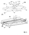
- FIG. 5 shows a variant of the invention, in which the antenna 100 includes two conductor loop assemblies 20.1, 20.2.
- Each of the conductor loop assemblies 20.1, 20.2 has the shape of in FIG. 1 shown embodiment.
- the conductor loop assemblies 20.1, 20.2 are arranged side by side with a mutual distance d.
- the distance d is, for example, in the range of 1 mm to several cm, z. B. 1 cm or a maximum of ten times the length of the single loop.
- additional decoupling capacitors and / or decoupling networks can be arranged.
- Each of the conductor loop arrangements 20.1, 20.2 is connected to the separate terminals 26.1 and 26.2 via its own network of parallel and serial capacitors 24.1, 25.1 and 24.2, 25.2.
- a comparison with the embodiment according to FIG. 4 increased flexibility in setting the antenna sensitivity achieved.
- Each of the conductor loop assemblies 20.1, 20.2 can be controlled independently of the other conductor loop arrangement.
- FIG. 6 is shown by way of example, as in the present invention, the field profile of the stripline resonator ( FIG. 6A ) and the field profile of the conductor loop arrangement ( FIG. 6B ), here an arrangement according to FIG. 4 or 5 to a superimposed field profile of the antenna 100 (FIG. FIG. 6C ) are added.
- the superimposed field profile in FIG. 6C illustrates the z-directional structured antenna sensitivity when e.g. B. on one of the conductor loops arrangements, an additional transmission amplitude is set.
- the field profile can be further modified by the measures mentioned in the other exemplary embodiments. It can be advantageous that even further conductor loop arrangements with reduced dimensions are arranged in the direction of the longitudinal extent of the stripline resonator.
- the antenna 100 shown embodiments is also the stripline resonator 10 according to Figure 1A intended.
- the conductor loop arrangement 20 is subdivided in the direction of the longitudinal extent of the stripline resonator 10 by a further conductor 27.
- the middle conductor section 27 in FIG Fig. 7 is interrupted by a network with the parallel and series capacitors 24, 25 and the terminals 26.
- Substitute way ( Fig. 8 ) the conductor 27 by a further capacitor 23.1, the like the capacitors 23 z. B. according to FIG. 1 is formed, be interrupted. With suitable dimensioning of the decoupling capacitor 23.1, two decoupled partial resonators are formed.
- the sub-resonators can via the terminals 26 or other separate feed points are used independently to control the antenna 100.
- the embodiments according to the FIGS. 7B and 8B are similar to a rotated "number 8 coil". As a result of the rotation, the field generated between the two partial resonators of the conductor loop arrangement 20 is advantageously also NMR-active.
- the embodiments according to the FIGS. 7B and 8B In particular, these can be used to partially or nearly cancel out the field of the stripline resonator 10, to reverse it, or to subject it to a gain with a predetermined amplification factor.
- the conductor loop assembly is constructed in this embodiment of ellipses or polygons. It is also not necessarily required that the two parts of the conductor loop arrangement have identical dimensions. Also, by varying the geometry of the two parts, the desired adaptation of the transmission / reception profile of the antenna can be provided.
- capacitors 23 are also incorporated in the conductor loop arrangement 20 proposed according to the invention in this embodiment. It is not absolutely necessary that capacitors are mounted at all positions shown. In some cases, unbalanced or deformed field profile due to runtime effects may well be desirable for parallel imaging, for RF shimming or for parallel transmission techniques.
- capacitor 23.1 can also be used for decoupling between the two parts of the conductor loop assembly 20.
- a phase shift of 180 ° between the two feed points (terminals 26.1, 26.2) of the two parts of the conductor loop arrangement is in FIG. 7 realized variant provided.
- the complete variable antenna 100 is the FIGS. 7B or 8B.
- the change of the sensitivity profile in these embodiments takes place mainly in a plane perpendicular to the longitudinal extent of the stripline resonator (eg xy plane). If the stripline resonator 10 and the conductor loop arrangement 20 are driven together, the field profile of the antenna 100 can be deformed in the desired manner.
- the transmission phases and amplitudes do not necessarily have to be the same.
- FIG. 9 1 shows a variant of the invention, in which the antenna 100 as a conductor loop arrangement 20 contains a simple conductor loop 21, which, with respect to the insulating dielectric 13, is mounted partially laterally on the surface of the dielectric 13 and partially penetrating the dielectric 13 (FIG. Figure 9A ).
- the stripline resonator 10 is shorted on one side.
- FIG. 9B shows an example of a generated with the antenna 100 field profile.
- the dielectric 13 (insulating body) consists for easy realization of three PP plates (thickness 5 mm, width 70 mm, length 300 mm). He is here drawn for simplicity's sake as a piece.
- the middle plate is divided into a 270 mm long piece and two 15 mm long pieces. On the side surfaces of the 270 mm long, middle piece is about Glued 12 microns thick copper foil with a width of 5 mm (equivalent to the thickness of the plate).
- This conductor is interrupted at the points shown in a width of about 5 mm and bridged with capacitors.
- a capacitance value of 20.9 pF was found for use of the stripline arrangement at 123.1 MHz (Lamor frequency for 1H at 2.9 T).
- This value is realized for example by non-magnetic chip capacitors with a capacity of 22 pF and at one or possibly at several points as a parallel connection of a non-magnetic chip capacitor (15 pF) with a non-magnetic variable capacitor (rotary capacitor, pipe trimmer or the like) with a variable capacity range from 0.5 pF to 10 pF.
- the set value for the variable tuning capacitor 24 is z. B. 27.4 pF.
- this information for the capacitors is only a guide and that other combinations lead to resonance at 123.1 MHz and that larger resonances can push the resonant frequency to lower frequencies and smaller capacitances to higher frequencies.
- this arrangement is adapted in the simplest case with a non-magnetic variable series capacitor 25 with a set value of 39.9 pF to 50 ohms. Again, this is a guideline influenced by loading effects, and so on. This arrangement is again brought to a total length of 300 mm at the two ends by the previously sawed 15 mm long PP end pieces.
- a short circuit for termination is provided, which is also made of 50 mm wide and 12 micron thick, self-adhesive copper foil. Between the conductor loop arrangement 20 and the stripline resonator 10, a decoupling of approximately 50 dB is achieved.
- variable antenna 100 with shrink tubing z. B. of polyolefin (colorless) wrapped.
- FIG. 9B shows, by way of example, the B1 field generated by the antenna 100 when the conductor loop arrangement 20 with a relative amplitude 3 W and a relative phase of -90 ° and the strip conductor resonator 10 with a relative amplitude of 1 W and a relative phase of 0 ° are controlled.
- FIG. 10 1 shows a further variant of the invention, in which the antenna 100 as conductor loop arrangement 20 contains a plurality of conductor loops 21.1, 21.2, 21.3, which are formed by parallel, rod-shaped conductors 27.1 in the insulating dielectric 13 ( Figure 10A ).
- the stripline resonator 10 is shorted on one side.
- FIG. 10B shows an example of a generated with the antenna 100 field profile.
- controllable antenna 100 In the manufacture of the controllable antenna 100 is also assumed by 3 sheets of PP (5 mm thick, 7 cm wide and 30 cm long). Two slots (about 1 mm wide) are milled into one of the three plates symmetrically to the center at a distance of 4.75 cm (or 14.25 cm) to about the middle of the plate. These slots serve to accommodate the four wires interrupted in the middle to form the rod-shaped conductors.
- the wires (Cu, Cu silver plated or similar materials with high conductivity for the HF) have a diameter of about 1 mm.
- the two outer conductor bars 27.1, 27.4 are capacitively bridged in the middle with 48.3 pF, while for the two middle conductor bars 27.2, 27.3, a value of 47.2 pF is optimal for a decoupling between the partial loops 21.1, 21.2, 21.3 of the conductor loop. Arrangement 20 has proved.
- the high frequency power for this complex conductor loop arrangement 20 is provided via one or more laterally arranged at an interruption of the conductor loop tuning capacitors 24, z. B. 24.6 pF fed.
- the high-frequency power can be applied at three locations in order to influence the behavior of the conductor loop arrangement 20.
- z. B. 5 to 25 pF used which has a value of z. B. 9.9 pF are set.
- the breaks on the opposite side of the conductor loop are capacitively bridged at 24.7 pF.
- the capacitance values given here can be set by variable capacitors or by a combination of a variable capacitor and a fixed capacitor.
- z. B. trim capacitors (2 to 50 pF) can be used.
- guide values that can be varied as needed.
- this insulator manufactured as a stack of stripline resonator 10 is glued from about 12 microns thick self-adhesive Cu film.
- the upper conductor 11 is 15 mm wide and 30 cm long, while the short circuit termination at the end of the dielectric 13 and the lower conductor 12 are made of 5 cm wide and 12 ⁇ m thick self-adhesive Cu film.
- a tuning capacitor 24, about 3 pF is arranged at the short-circuited opposite open end.
- the stripline resonator is connected to a matching capacitor 25, about 3 pF.
- the individual conductor loops 21.1, 21.2, 21.3 of the conductor loop arrangement 20 are decoupled from one another with approximately 20 dB, while the decoupling to the stripline resonator is approximately 40 dB.
- FIG. 10B shows by way of example the B1 field generated by the antenna 100 when all the conductor loops 21.1, 21.2, 21.3 of the conductor loop arrangement 20 are driven in opposite phase.
- FIG. 11 shows a further variant of the invention, in which the antenna 100 as a conductor loop arrangement 20 four rhombus-shaped conductor loops 21.1, 21.2, 21.3, 21.4 contains.
- the controllable antenna 100 ( Figure 11A ) also three PP plates (5 mm thick, 7 cm wide and 30 cm long) are used. In one of the three plates, squares with an edge length of approx. 5cm are milled out symmetrically to the middle. These breakthroughs are at their inner cut surfaces pasted with conductive foil to form the conductor loops.
- the breaks at the right corner of the right quadrilateral and at the left corner of the left quadrilateral are bridged with capacitors 23.1, while the locations where the conductor loops in the middle of the plate adjoin each other are bridged with capacitances 23.2 of 350 pF.
- the two outer conductor loops 21.1, 21.4 are tuned with 26.5 pF and adjusted with 4.2 pF. Opposite the tuning capacitor is still a capacitor with a value of 75.3 pF.
- the two middle conductor loops 21.2, 21.3 are matched with 22 pF and adjusted with 3.5 pF.
- Opposite the tuning capacitor is a capacitor of 73 pF.
- the stripline resonator 10 is tuned to 2.9 pF and adjusted to 3.2 pF. It should be noted that the capacitance values given here can be set by variable capacitors or by a combination of a variable capacitor and a fixed capacitor. The examples given are guidelines that can be modified if necessary.
- the remainder of the apertures are refilled with PP of 5 mm thickness to minimize or avoid disturbance of the field in the dielectric 13.
- another PP plate is placed on top and bottom (30 cm long, 7 cm wide and 5 mm thick).
- this stacked dielectric 13 (insulator) of the stripline resonator 10 is glued from about 12 microns thick, self-adhesive Cu film.
- the upper conductor 11 is 15 mm wide and 30 cm long, while the short-circuit termination conductor and the lower conductor 12 are made of 5 cm wide and 12 ⁇ m thick self-adhesive Cu film.
- a tuning capacitor (about 3 pF) is placed.
- the stripline resonator 10 is connected to a matching capacitor (about 3 pF).
- the individual conductor loops of the conductor loop arrangement 20 are decoupled with one another by about 20 dB, while the decoupling to the stripline resonator is about 40 dB.
- FIG. 11B shows by way of example the B1 field generated by the antenna 100 when all the conductor loops 21.1, 21.2, 21.3, 21.4 of the conductor loop arrangement 20 are driven with different amplitudes and phases.
- FIGS. 12 to 14 schematically illustrate further embodiments of the antenna 100 according to the invention, in which the conductor loop arrangement 20 comprises a plurality of conductor loops 21, 22 (and 28).
- the conductor loops 21, 22, 28 form a stacked structure in the dielectric 13 of the stripline resonator 10.
- the shape of the individual conductor loops may be selected depending on the requirements of the chosen invention. It can z. B. simple loops (corresponding FIGS. 1B, 9 ) or "digit 8 orders" (according to FIG. 4A, 10 ) or combinations thereof.
- the formation of the multi-loop conductor loop assembly may be extended in multiple directions (eg, with multiple parallel conductor portions).
- FIG. 12 According to the Figures 12 and 14 are, for example, two conductor loops 21, 22 arranged one above the other. Also for this variant of the invention is a simple stripline resonator 10 according to Figure 1A used.
- the present invention laterally projecting conductor loop assembly 20 consists of two conductor loops 21, 22.
- the stripline resonator 10 and the two superimposed conductor loops 21, 22 decoupled In exactly symmetrical structure of the arrangement of FIG. 12 are the stripline resonator 10 and the two superimposed conductor loops 21, 22 decoupled, so that the phases and amplitudes at the three feed points of the stripline resonator 10 and the conductor loops 21, 22 can be advantageously selected independently of each other. This results in favorable conditions for parallel imaging, for RF shimming or for parallel transmission techniques.
- the field profile can be modified by constructing multiple conductor loop arrangements modeled after FIG. 12 with reduced in the longitudinal direction of the conductor strip resonator dimensions are arranged in this direction with distance or overlapped.
- the conductor loops can be arranged alternately stacked with and without spacing in the longitudinal direction of the stripline resonator 10. This achieves better RF shimming in the case of transmission and higher acceleration factors in parallel imaging.
- FIG. 12 stacking principle shown can, if necessary z. B. according to FIG. 13 be extended.
- measures may be taken for decoupling between overlying conductor loop assemblies according to the prior art.
- three conductor loops 21, 22, 28 can be arranged one above the other.
- z. B. five or more stacked conductor loops form a stack. As shown, the conductor loops can be aligned in the stack relative to one another or offset relative to each other.
- FIG. 15 shows an example of an embodiment of a switching device 40, which is used to connect the antenna 100 to the receiver 60 or the transmitter 70 of the MR device (see figure 3 ) is provided.
- the switching device 40 is provided for use with the stripline resonator 10 and the conductor loop assembly (s) 20, respectively.
- the switching device 40 has a group of PIN diodes 41 which are connected via a separating capacitor 42.1 and a coaxial line to one of the connections (26, see, for example, US Pat. FIG. 1B ) of the antenna 100 are connected.
- the switching device 40 furthermore has a changeover switch 51 with which a positive switching voltage Us (eg +5 V) can optionally be switched to one of the PIN diodes 41.
- a positive switching voltage Us eg +5 V
- a negative bias also called zero
- T / R switch for the different operating states
- the antenna 100 is connected to the preamplifier of the receiver 60.
- the respective PIN diodes in the current path are open.
- other elements such as the further separation capacitor 42.2 other elements such. B.
- a phase shifter can be provided.
- a reverse voltage eg, +5 V
- the transmitter is connected to the antenna (classic transmission case).
- switch positions S2 to S5 use is made of the coupling between an antenna 10 connected to the RF transmitter with conductor loop arrangement 20 to other antennas 10 with conductor loop arrangement 20, or within an antenna 10 to the conductor loop arrangement 20 and influences its strength. As a result, the amplitude of the generated magnetic field is influenced so that the desired total field, z. B. according to predetermined specifications, can be formed.
- a varactor diode 43 is switched on, with the appropriate dimensioning of the tuning state of the antenna 100 and the conductor loop arrangement 20 can be remotely controlled.
- the variable capacitor also causes a change in the tuning state without remote control in the switch position S3.
- an inductance is connected in parallel to the tuning capacitor.
- the inductance together with the capacitor 24 (see FIG. 16 ) of the stripline resonator 10 or a corresponding capacitor of a conductor loop arrangement form a parallel resonant circuit, so that the stripline resonator 10 or a conductor loop arrangement opens.
- the parallel capacitor of the stripline resonator 10 or a corresponding capacitor of the conductor loop arrangement is short-circuited in terms of HF.
- the preamplifier of the receiver 60 is disconnected from the switching device 40, since the preamplifier is short-circuited at the input via another PIN diode 44 and the ⁇ / 4 cable at the other end is high-impedance.
- the change-over switch 51 can be designed in a manner known per se as an electronic switch, so that the entire switching device 40 can be remotely controlled.
- FIG. 16 schematically different variants of the control and termination of the stripline resonator 10th illustrated with the first and second conductor strips 11, 12.
- Figure 16B shows different termination variants, which at the connections C / D (see also Figure 1A ) can be provided.
- the termination options include in particular a capacitive termination, an inductive termination, a short circuit, an open termination, a termination with a resistance that is not equal to the characteristic impedance of the stripline resonator 10, and a termination with a resonant circuit (tank circuit) in series with a series capacitor ,
- FIG. 16C illustrates two possibilities for feeding the RF voltage via the tuner 30 to the terminals A / B (corresponding to the terminals 26, see FIG. 1 ).
- FIG. 16C is provided an impedance matching with a so-called ⁇ -circle (Collins filter) while Figure 16D the network of parallel and series capacitors 24, 25 for tuning and matching the stripline resonator 10 shows.
- a two-dimensional array 200 is shown which may be constructed from antennas 100 according to the invention, in particular according to at least one of the embodiments described above. It should be expressly pointed out that it may be beneficial for certain investigations to use variable antennas 100 of different embodiments alternately or in a predetermined order.
- the antennas 100 are aligned in the direction of a cylinder axis (z-direction), the z. B. coincides with the direction of the static magnetic field B 0 of the MR device.
- the antennas 100 or else only the stripline resonators on a cylinder jacket or differently shaped anatomically adapted shaped body to be at a certain angle to the direction of the static Magnetic field (eg along a helix) are arranged. In this case, an additional structuring of the transmission / reception profile in the direction of the static magnetic field is achieved.
- variable antennas described according to the invention can also be operated in quadrature.
Abstract
Description
Die Erfindung betrifft eine Antenne für ein Magnetresonanzgerät (MR-Gerät), insbesondere eine Antenne mit den Merkmalen des Oberbegriffs von Anspruch 1. Die Erfindung betrifft des Weiteren eine Antennenanordnung für ein MR-Gerät und ein Verfahren zum Betrieb des MR-Gerätes. Die Hauptanwendung der Erfindung besteht in der Magnetresonanz-Bildgebung (MR-Bildgebung, magnetic resonance imaging, MRI) und in der Magnetresonanz-Spektroskopie.The invention relates to an antenna for a magnetic resonance device (MR device), in particular to an antenna having the features of the preamble of claim 1. The invention further relates to an antenna arrangement for an MR device and to a method for operating the MR device. The main application of the invention is in magnetic resonance imaging (MRI, MRI) and in magnetic resonance spectroscopy.
Die magnetische Kernresonanz hat sich als ein wichtiges Bildgebungs- und Analyseverfahren, insbesondere in der Medizin, etabliert. Hierbei wird ausgenutzt, dass magnetische Kernmomente im statischen Magnetfeld bei Einstrahlung elektromagnetischer Energie einer definierten Frequenz ausgelenkt werden können. Die Frequenz bestimmt sich aus der Stärke des statischen Magnetfeldes und der gyromagnetischen Konstante der untersuchten Atomkerne. Die infolge der Anregung kohärent präzedierenden Kernmomente erzeugen ein magnetisches Induktionssignal, das mit geeigneten Spulen registriert und zur Rekonstruktion eines Bildes genutzt werden kann. Grundsätzlich können dieselben Spulen sowohl zum Anregen, also Senden eines Hochfrequenz-(HF-)Signals, als auch zum Empfang genutzt werden. Da das Signal von Spulen im Nahfeld um so stärker und inhomogener wird, je näher man dem Leiter der HF-Spule kommt, hat man zuerst oft mit so genannten Volumenspulen relativ homogen HF-Energie in das zu untersuchende Volumen eingestrahlt und kleine Oberflächenspulen zum Empfang benutzt. Im Vergleich zum Empfang mit Volumenspulen kann man dabei das Signal-zu-Rausch-Verhältnis (signal-to-noise ratio, SNR) beträchtlich steigern. Allerdings engt man auch das Gesichtsfeld (field of view, FOV) stark ein.Nuclear magnetic resonance has become established as an important imaging and analysis method, especially in medicine. This exploits the fact that magnetic core moments in the static magnetic field can be deflected when irradiation of electromagnetic energy of a defined frequency. The frequency is determined by the strength of the static magnetic field and the gyromagnetic constant of the investigated atomic nuclei. The nuclear moments coherently precessing as a result of the excitation generate a magnetic induction signal which can be registered with suitable coils and used to reconstruct an image. In principle, the same coils can be used both for exciting, thus transmitting a high-frequency (RF) signal, as well as for receiving. Since the signal from coils in the near field becomes stronger and more inhomogeneous the closer one gets to the conductor of the RF coil, one often first has relatively homogeneous with so-called volume coils RF energy is injected into the volume to be examined and small surface coils are used for reception. Compared to receiving with volume coils, the signal-to-noise ratio (SNR) can be increased considerably. However, one also narrows the field of view (FOV) strongly.
Seit etwa 1990 werden zur Erhöhung des SNR in spulennahen Bereichen Antennenarrays verwendet, die aus mehreren einzelnen Spulen (im Weiteren Antennen genannt) zusammengesetzt sind (siehe z. B. Roemer PB, Edelstein WA. Nuclear magnetic resonance (NMR) imaging with multiple surface coils.
In der Folgezeit wurden Arrays für unterschiedliche Anwendungen optimiert. Sie unterschieden sich insbesondere nach der geometrischen Anordnung der Antennen. So sind Arrays bekannt, bei denen die Teilspulen längs einer Linie (siehe z. B.
Beim "klassischen" Arraydesign werden ausschließlich Magnetfeld-Gradienten für die Kodierung der Ortsinformation genutzt, und die Verbesserung des SNR im FOV steht im Vordergrund. Nach den ersten Arbeiten zur Parallelbildgebung (siehe z. B.
Unter dem Gesichtspunkt der parallelen Bildrekonstruktion im k-Raum (z. B. SMASH- oder GRAPPA-Verfahren) sollten die Antennenelemente so ausgerichtet sein, dass die fehlenden Rohdatenzeilen rekonstruiert werden können. Vom Standpunkt der parallelen Bildrekonstruktion im Ortsraum (z. B. SENSE-Verfahren) sollten die Teilantennen so angeordnet sein, dass Überfaltungen rechnerisch nachträglich rückgängig gemacht werden können. Mit linearen Arrays erhält man eine maximale räumliche Information in einer Richtung, während gitterartig angeordnete Arrayelemente (die auch auf gekrümmten Flächen angeordnet sein können) räumliche Informationen aus mehreren Richtungen liefern. Es wurde weiterhin gefunden, dass simultanes "undersampling" in mehren Richtungen zu einem geringeren Geometriefaktor g führt.From the viewpoint of parallel image reconstruction in k- space (eg, SMASH or GRAPPA method), the antenna elements should be aligned so that the missing raw data lines can be reconstructed. From the standpoint of parallel image reconstruction in spatial space (eg SENSE method), the subantennas should be arranged such that hyperfoldings can be computationally retrospectively reversed. With linear arrays you get a maximum spatial information in one direction while gridded array elements (which may also be arranged on curved surfaces) provide spatial information from multiple directions. It has also been found that simultaneous undersampling in several directions leads to a lower geometry factor g.
Die Empfindlichkeit der Teilantennen ist eine komplexe Funktion der Position und geht in den Rekonstruktionsalgorithmus ein. Somit stellt neben der Amplitude auch die Phase des in einem Arrayelement empfangenen Signals eine wichtige Informationsquelle zur Ortskodierung dar. So kann man beispielsweise Antennen in Form der Ziffer "8" in Kombination mit einfachen Kreisspulen als unabhängige Antennen im Sinn der Parallelbildgebung betrachten (siehe z. B.
Insbesondere bei gitterartigen Arrays wurden bei einer Anordnung mit einem Abstand ("gap") zwischen den Antennen im Vergleich zu einer Anordnung mit Überlappung verbesserte g-Faktoren gefunden. In
Bei den herkömmlichen Arrayantennen spielt die Kopplung zwischen den einzelnen Teilantennen eine große Rolle, da sie zur Verschlechterung des Abstimmverhaltens, zur Verschlechterung des SNR und zu Rekonstruktionsfehlern führen kann. Neben den bereits genannten Verfahren der Überlappung der Spulen und der Vorverstärkerentkopplung nutzt man aufwendige kapazitive bzw. induktive Entkoppelnetzwerke (siehe z. B.
Die oben beschriebenen Arrays auf der Basis von Spulen haben den generellen Nachteil eines hohen Aufwands bei der Realisierung der Arrays mit relativ vielen Teilantennen. Ihr Aufbau ist insbesondere bei hoher Spulenpackungsdichte sehr aufwendig. Auch der Spulenabgleich ist oft sehr schwierig. Speziell bei höheren MR-Frequenzen, bei denen die Antennendimensionen in der Größenordnung der Wellenlänge liegen, wird es unmöglich, Antennen auf der Basis von Spulen abzustimmen. Wegen der aufwendigen Herstellung (einschließlich Abgleich) und der begrenzten Packungsdichte besteht ein Interesse an alternativen Lösungen.The coil-based arrays described above have the general disadvantage of a high cost in realizing the arrays with relatively many sub-antennas. Their structure is very expensive, especially at high coil packing density. Also the coil adjustment is often very difficult. Especially at higher MR frequencies, where the antenna dimensions are on the order of the wavelength, it becomes impossible to tune antennas based on coils. Because of the elaborate manufacturing (including balancing) and the limited packing density, there is an interest in alternative solutions.
Eine erhebliche Vereinfachung beim Aufbau eines Arrays bieten Antennen auf der Basis der Streifenleiter-Technik (siehe z. B.
Bei planaren Streifenleiter-Arrays ist das Empfindlichkeitsprofil senkrecht zu den Streifenleitern nahezu sinusförmig (
Streifenleiter-Antennen haben jedoch im Vergleich zu Spulen die Nachteile einer geringeren Eindringtiefe und einer schwach ausgeprägten Empfindlichkeitsvariation in Richtung der Streifenleiter, was insbesondere eine beschleunigte Bilderfassung in Richtung der Streifenleiter verhindert oder zumindest sehr erschwert.However, stripline antennas have the disadvantages of a lower penetration depth and one compared to coils weak sensitivity variation in the direction of the strip conductor, which in particular prevents or at least greatly complicates accelerated image acquisition in the direction of the strip conductors.
Hinsichtlich der Eindringtiefe lassen sich zwar aus Streifenleitern aufgebaute Resonatoren in gewissem Maße optimieren, indem man beispielsweise die Dicke des Dielektrikums erhöht. Allerdings sind diesen Bemühungen Grenzen gesetzt, da man dann bei höheren Substratdicken diese Anordnungen nicht mehr im Quasi-TEM-Modus betreiben kann (
Aus der Literatur sind Möglichkeiten zur Beeinflussung des Feldprofils von Streifenleiter-Resonatoren bekannt. Diese dort offenbarten Steuermöglichkeiten sind jedoch "statischer" Natur, d.h. sie können nicht einfach während des Experiments modifiziert werden. Zur ersten Gruppe gehören Veränderungen der Dielektrizitätskonstante des Dielektrikums für den Aufbau der Streifenleiter und Änderungen der Geometrie der Antennenanordnung, während die zweite Gruppe hauptsächlich Maßnahmen zur sequentiellen Änderung von Terminierungen mittels schneller Schaltdioden beinhaltet. Damit gelingt es zwar über die Verschiebung der sinusförmigen Intensitätsverteilung in Richtung der Steifenleiter in Kombination mit geometrischen Maßnahmen, das Intensitätsprofil hinsichtlich geometrischer Gegebenheiten zu optimieren. Hinsichtlich der Anforderungen an das Empfindlichkeitsprofil in Richtung der Streifenleiter zur beschleunigten Bildaufnahme erreicht man mit diesen Maßnahmen keine optimalen Werte.From the literature possibilities for influencing the field profile of stripline resonators are known. However, these control possibilities disclosed therein are "static" in nature, ie they can not be easily modified during the experiment. The first group includes changes in the dielectric constant of the dielectric for the construction of the strip conductors and changes in the geometry of the antenna arrangement, while the second group mainly includes measures for the sequential change of terminations by means of fast switching diodes. Thus, it is possible to optimize the intensity profile with respect to geometrical conditions via the shift of the sinusoidal intensity distribution in the direction of the stiffener in combination with geometric measures. With regard to the requirements for the sensitivity profile in the direction of the strip conductors for accelerated image recording, these measures do not achieve optimum values.
Die Aufgabe der Erfindung ist es, eine verbesserte Antenne bereitzustellen, mit der die Nachteile der herkömmlichen Antennen vermieden werden. Der Erfindung liegt insbesondere die Aufgabe zugrunde, eine veränderbare Antenne für ein MR-Gerät bereitzustellen, die eine verbesserte Strukturierung der Antennenempfindlichkeit und/oder eine hohe Spulenpackungsdichte ermöglicht. Die Aufgabe der Erfindung ist es des Weiteren, eine verbesserte Antennenanordnung (Antennenarray) bereitzustellen, mit der die Nachteile der herkömmlichen Antennenanordnungen vermieden werden. Die Aufgabe der Erfindung ist es auch, ein verbessertes Verfahren zum Betrieb der Antennen oder Antennenanordnungen bereitzustellen. Das Verfahren soll insbesondere zur Steuerung der Antennen oder Antennenanordnungen und zu einer Erhöhung des räumlichen und/oder zeitlichen Auflösungsvermögens von MR-Verfahren geeignet sein.The object of the invention is to provide an improved antenna with which the disadvantages of the conventional antennas are avoided. The invention is in particular the object of providing a variable antenna for an MR device, which allows an improved structuring of the antenna sensitivity and / or a high package density. The object of the invention is furthermore to provide an improved antenna arrangement (antenna array) with which the disadvantages of the conventional antenna arrangements are avoided. The object of the invention is also to provide an improved method for operating the antennas or antenna arrangements. The method should be suitable in particular for controlling the antenna or antenna arrangements and for increasing the spatial and / or temporal resolving power of MR methods.
Diese Aufgaben werden mit einer Antenne, einer Antennenanordnung, einem MR-Gerät und Verfahren mit den Merkmalen der unabhängigen Ansprüche gelöst. Vorteilhafte Ausführungsformen und Anwendungen der Erfindung ergeben sich aus den abhängigen Ansprüchen.These objects are achieved with an antenna, an antenna arrangement, an MR device and methods having the features of the independent claims. Advantageous embodiments and applications of the invention will become apparent from the dependent claims.
Gemäß einem ersten Gesichtspunkt wird die genannte Aufgabe der Erfindung durch die allgemeine technische Lehre gelöst, eine Antenne für ein MR-Gerät bereitzustellen, die für eine Anregung und/oder Erfassung einer Magnetresonanz in einem zu untersuchenden Objekt eingerichtet ist und mindestens einen Streifenleiter-Resonator mit mindestens einem Streifenleiter und mindestens einer Leiterschleifen-Anordnung mit mindestens einer Leiterschleife umfasst, die mit mindestens einem Kondensator unterbrochen ist. Die mindestens eine Leiterschleifen-Anordnung ist in unmittelbarer Umgebung des Streifenleiter-Resonators angeordnet, so dass die Empfindlichkeit der Antenne durch überlagerte Empfindlichkeitsprofile des mindestens einen Streifenleiter-Resonators und der mindestens einen Leiterschleifen-Anordnung gebildet wird. Mit der Leiterschleifen-Anordnung kann die Empfindlichkeit der Antenne beeinflusst oder gesteuert werden, so dass die Leiterschleifen-Anordnung auch als Steuervorrichtung oder Leiterschleifen-Resonator bezeichnet werden kann.According to a first aspect, the object of the invention is achieved by the general technical teaching to provide an antenna for an MR device, which is set up for excitation and / or detection of magnetic resonance in an object to be examined and at least one stripline resonator with at least one stripline and at least one conductor loop arrangement having at least one conductor loop, which comprises at least one capacitor is interrupted. The at least one conductor loop arrangement is arranged in the immediate vicinity of the stripline resonator, so that the sensitivity of the antenna is formed by superposed sensitivity profiles of the at least one stripline resonator and the at least one conductor loop arrangement. With the conductor loop arrangement, the sensitivity of the antenna can be influenced or controlled, so that the conductor loop arrangement can also be referred to as a control device or conductor loop resonator.
Ein wichtiger Vorteil der erfindungsgemäßen veränderbaren Antenne besteht darin, dass sie sich gegenüber herkömmlichen Antennen auf Wellenleiter-(Streifenleiter-)Basis insbesondere durch eine hohe Spulendichte und signifikante Variation des Empfindlichkeitsprofils in allen drei Raumrichtungen und Steuermöglichkeiten in weiten Grenzen auszeichnet. Vorteilhafterweise werden mit der Antenne die optimalen Voraussetzungen für die Parallelbildgebung senkrecht zu den Streifenleitern mittels der Leiterschleifen-Anordnung auf alle drei Raumrichtungen ausgedehnt. Die räumliche und/oder zeitliche Auflösung im MR-Experiment kann verbessert werden. Es ergeben sich zusätzlich Verbesserungen für HF-Shimming oder für parallele Sendetechniken. Weitere Vorteile der Antenne bestehen darin, dass sie einfach und kostengünstig herstellbar ist.An important advantage of the variable antenna according to the invention is that it distinguishes itself from conventional waveguide (stripline) based antennas in particular by a high coil density and significant variation of the sensitivity profile in all three spatial directions and control possibilities within wide limits. Advantageously, with the antenna, the optimal conditions for the parallel imaging perpendicular to the strip conductors by means of the conductor loop arrangement extended to all three spatial directions. The spatial and / or temporal resolution in the MR experiment can be improved. There are also improvements for RF shimming or for parallel transmission techniques. Other advantages of the antenna are that it is easy and inexpensive to produce.
Im Unterschied zu den beschränkten Steuermöglichkeiten herkömmlicher Antennen erlaubt die erfindungsgemäße Leiterschleifen-Anordnung insbesondere in Richtung der Streifenleiter des Streifenleiter-Resonators lokal wirkungsvolle Eingriffe in das Empfindlichkeitsprofil der Antenne, die von der Auslöschung in begrenzten Bereichen bis hin zu einer signifikanten Erhöhung reichen. Damit weicht das Empfindlichkeitsprofil der Antenne in dieser Richtung merklich vom Zustand ohne Leiterschleifen-Anordnung ab, und eine Anregung gemäß verschiedenen Empfindlichkeitsprofilen in Kombination mit mehreren HF-Sendern bzw. geeignet aufbereiteter Sendesignalen kann parallel im Untersuchungsobjekt erfolgen. Damit werden zusätzliche Freiheitsgrade zur selektiven räumlichen Anregung von 3-dimensionalen Objekten erreicht. Somit wird mit der erfindungsgemäß vorgeschlagenen Antenne insbesondere hinsichtlich der 3D-Beschleunigung eine optimale Antennenanordnung erreicht.In contrast to the limited control options of conventional antennas, the conductor loop arrangement according to the invention, particularly in the direction of the stripline of the stripline resonator, allows locally effective interferences in the sensitivity profile of the antenna, ranging from the extinction in limited ranges to a significant increase. Thus, the sensitivity profile of the antenna in this direction differs noticeably from the state without a conductor loop arrangement, and an excitation according to different sensitivity profiles in combination with a plurality of RF transmitters or suitably processed transmit signals can take place in parallel in the examination subject. This achieves additional degrees of freedom for the selective spatial excitation of 3-dimensional objects. Thus, with the antenna proposed according to the invention, an optimal antenna arrangement is achieved, in particular with regard to the 3D acceleration.
Gemäß einem zweiten Gesichtspunkt wird die genannte Aufgabe der Erfindung durch die allgemeine technische Lehre gelöst, eine Antennenanordnung bereitzustellen, die eine Vielzahl von erfindungsgemäßen Antennen umfasst. Die Antennenanordnung ist eine zu einem Feld (Array) zusammengefasste Gruppe von Antennen. Sie wird zur Erzeugung und zum Empfang von magnetischen Wechselfeldern im Nahfeld für den Einsatz zur MR-Bildgebung und MR-Spektroskopie benutzt. Sie eignet sich besonders beim Senden zur lokalen Anregung von begrenzten Gebieten oder zur Homogenisierung der Anregung insbesondere bei höheren Frequenzen. Beim Empfang von MR-Signalen zeichnet sie sich durch eine Erhöhung des SNR in spulennahen Bereichen und/oder eine beschleunigten Bildaufnahme aus.According to a second aspect, the object of the invention is achieved by the general technical teaching to provide an antenna arrangement comprising a plurality of antennas according to the invention. The antenna arrangement is a group of antennas combined into a field (array). It is used to generate and receive alternating magnetic fields in the near field for use in MR imaging and MR spectroscopy. It is particularly suitable for local excitation of limited areas or homogenization of excitation, especially at higher frequencies. When receiving MR signals, it is characterized by an increase in the SNR in coil-near areas and / or an accelerated image acquisition.
Ein weiterer wichtiger Vorteil der erfindungsgemäßen Antennenanordnung besteht in der einfachen Realisierung. Mit einer Aneinanderreihung von mehreren erfindungsgemäßen Antennen kann ein dreidimensionales Array geschaffen werden, das ggf. geometrisch an eine vorbestimmte Form des zu untersuchenden Objekts, z. B. an eine zu untersuchende Körperregion (z. B. den Kopf oder ein Gelenk) angepasst werden kann und eine hohe Flexibilität bezüglich des Einsatzes ermöglicht.Another important advantage of the antenna arrangement according to the invention is the simple realization. With a juxtaposition of several antennas according to the invention, a three-dimensional array can be created, which may be geometrically connected to a predetermined shape of the object to be examined, z. B. can be adapted to a body region to be examined (eg., The head or a joint) and allows high flexibility with respect to the use.
Gemäß einem dritten Gesichtspunkt wird die genannte Aufgabe der Erfindung durch die allgemeine technische Lehre gelöst, ein MR-Gerät bereitzustellen, das mindestens eine erfindungsgemäße Antenne und/oder mindestens eine erfindungsgemäße Antennenanordnung umfasst.According to a third aspect, the stated object of the invention is achieved by the general technical teaching to provide an MR apparatus which comprises at least one antenna according to the invention and / or at least one antenna arrangement according to the invention.
Gemäß einem vierten Gesichtspunkt wird die genannte Aufgabe der Erfindung durch die allgemeine technische Lehre gelöst, ein Verfahren zur MR-Bildgebung oder MR-Spektroskopie an einem zu untersuchenden Objekt bereitzustellen, bei dem eine Anregung und/oder eine Erfassung einer Magnetresonanz in dem Objekt mit mindestens einer erfindungsgemäßen Antenne und/oder mindestens einer erfindungsgemäßen Antennenanordnung vorgesehen ist. Das Verfahren zeichnet sich insbesondere durch eine verbesserte Steuerung der mindestens einen Antenne aus. Das Verfahren ermöglicht insbesondere eine Beeinflussung der Sende- und Empfangsempfindlichkeiten der Antenne(n) und somit deren Optimierung während der Untersuchung.According to a fourth aspect, the object of the invention is achieved by the general technical teaching to provide a method for MR imaging or MR spectroscopy on an object to be examined, in which an excitation and / or detection of a magnetic resonance in the object with at least an antenna according to the invention and / or at least one antenna arrangement according to the invention is provided. The method is characterized in particular by an improved control of the at least one antenna. In particular, the method makes it possible to influence the transmission and reception sensitivities of the antenna (s) and thus their optimization during the examination.
Der Streifenleiter-Resonator der erfindungsgemäßen Antenne wird mittels verlustarmer Wellenleiter aufgebaut, die auf einem Dielektrikum oder selbsttragend angeordnet und bezüglich einer oder mehrerer Larmor-Frequenzen resonant abgestimmt sind. Die Funktion des Streifenleiter-Resonators baut auf dem aus der Leitungstheorie bekannten Sachverhalt auf, dass sich auf Wellenleitern stehende Wellen ausbilden, wenn man einen Wellenleiter nicht mit einem ohmschen Widerstand abschließt, dessen Größe dem Wellenwiderstand entspricht. Eigenschaften von auf Wellenleitern basierenden Resonatoren sind an sich aus dem Stand der Technik bekannt. Einzelheiten können z. B. aus
Zur Veränderung der Antennenempfindlichkeit, insbesondere zur Variation des Feldprofils wird erfindungsgemäß mindestens ein weiterer, vorzugsweise schichtförmiger Leiter etwa senkrecht zu dem bereits vorhandenen Streifenleiter innerhalb und/oder außerhalb des Dielektrikums des Streifenleiter-Resonators angeordnet. Der schichtförmige Leiter bildet eine geschlossene Schleife, die an mindestens einer Stelle mit mindestens einem Kondensator unterbrochen ist. Mit dem mindestens einen Kondensator, ggf. durch Verwendung weiterer Reaktanzen, kann die Schleife ebenfalls auf eine oder mehrere Larmor-Frequenzen abgestimmt werden. Diese zusätzlich angebrachte leitfähige Struktur, die resonant abgestimmt ist, ggf. auch verstimmt, geöffnet oder kurzgeschlossen werden kann, wird hier als "Leiterschleifen-Anordnung" bezeichnet. Mit der Leiterschleifen-Anordnung wird die Antennenempfindlichkeit beeinflusst.For changing the antenna sensitivity, in particular for varying the field profile, at least one further, preferably layer-shaped conductor is arranged approximately perpendicular to the stripline already present inside and / or outside the dielectric of the stripline resonator. The layered conductor forms a closed loop which is interrupted at least at one point with at least one capacitor. With the at least one capacitor, if necessary by using further reactances, the loop can also be tuned to one or more Larmor frequencies. This additionally attached conductive structure, which is resonantly tuned, may also be detuned, opened or short-circuited, is referred to herein as a "looped conductor arrangement". The conductor loop arrangement affects the antenna sensitivity.
Die Erfinder haben festgestellt, dass die zusätzlich innerhalb und/oder außerhalb vom Streifenleiter-Resonator angebrachte Leiterschleifen-Anordnung bei geeigneter Dimensionierung weitgehend vom Streifenleiter-Resonator entkoppelt ist oder ggf. zusätzlich durch kapazitive bzw. induktive Entkoppelnetzwerke entkoppelt werden kann. So ist es möglich, sowohl den Streifenleiter-Resonator als auch die Leiterschleifen-Anordnung unabhängig voneinander anzusteuern. Die vom Streifenleiter-Resonator und von der Leiterschleifen-Anordnung erzeugten Felder überlagern sich im zu untersuchenden Objekt je nach Phasenlage und Amplitude der angeschlossenen Sender konstruktiv bzw. destruktiv. Somit kann man das resultierende Feldprofil in weiten Grenzen verändern und den Erfordernissen der Untersuchung anpassen (z. B. so genanntes "HF-Shimming" oder parallele Sendetechniken). Gleiches gilt für den Empfangsfall: auch hier hat man die Möglichkeit, die Signale einzeln zu nutzen oder mittels Phasenschiebern in unterschiedlicher Weise zu kombinieren und für Verfahren zur Parallelbildgebung zu nutzen.The inventors have found that the additionally mounted inside and / or outside of the stripline resonator conductor loop arrangement is decoupled with suitable dimensioning largely from the stripline resonator or possibly additionally decoupled by capacitive or inductive decoupling networks. Thus, it is possible to drive both the stripline resonator and the conductor loop arrangement independently of each other. The fields generated by the stripline resonator and the conductor loop arrangement are superimposed structurally or destructively in the object to be examined, depending on the phase position and amplitude of the connected transmitters. Thus, one can change the resulting field profile within wide limits and adapt it to the requirements of the investigation (eg so-called "RF shimming" or parallel transmission techniques). same for for the reception case: here, too, one has the possibility to use the signals individually or to combine them by means of phase shifters in different ways and to use them for methods for parallel imaging.
Die Leiterschleifen-Anordnung weist mindestens eine Leiterschleife auf, deren Leiter vorzugsweise durch den mindestens einen Kondensator unterbrochen ist. Der Leiter ist vorzugsweise schichtförmig gebildet. Schichtförmige Leiter können Vorteile in Bezug auf die Formung des Feldprofils, die Verringerung der kapazitiven Kopplung und die Herstellung der Antenne haben. Alternativ können jedoch, insbesondere in Abhängigkeit von der konkreten Anwendung der Erfindung, Leiter mit anderen Querschnittsformen, z. B. Drahtleiter mit einem kreisförmigen Querschnitt, vorgesehen sein.The conductor loop arrangement has at least one conductor loop whose conductor is preferably interrupted by the at least one capacitor. The conductor is preferably formed in layers. Layered conductors may have advantages in terms of shaping the field profile, reducing capacitive coupling, and manufacturing the antenna. Alternatively, however, in particular depending on the specific application of the invention, conductors having other cross-sectional shapes, for. B. wire conductor with a circular cross-section, may be provided.
Wenn gemäß einer bevorzugten Variante der Erfindung das von der Leiterschleifen-Anordnung erzeugte Feld relativ zu dem vom Streifenleiter-Resonator erzeugten Feld orthogonal ausgerichtet ist, ergeben sich Vorteile hinsichtlich der Entkopplung zwischen Leiterschleifen-Anordnung und Streifenleiterresonator. Es kann weiterhin vorteilhaft sein, orthogonal zueinander stehende Streifenleiter-Resonatoren in Kombination mit ihren Leiterschleifen-Anordnungen in Quadratur zu betreiben. Dies führt zu einer Verminderung der erforderlichen Sendeleistung und zu einem verbesserten SNR beim Empfang. Diese Vorteile basieren insbesondere auf der Erkenntnis, dass es bei in Quadratur betriebenen Spulen zu einer Halbierung der erforderlichen Sendeleistung kommt, und dass sich im Empfangsfall das SNR um den Faktor 1,4 erhöht.If according to a preferred variant of the invention, the field generated by the conductor loop arrangement is oriented orthogonally relative to the field generated by the stripline resonator, there are advantages in terms of the decoupling between conductor loop arrangement and stripline resonator. It may also be advantageous to operate in a mutually orthogonal stripline resonators in combination with their conductor loop arrangements in quadrature. This leads to a reduction of the required transmission power and to an improved SNR during reception. These advantages are based, in particular, on the recognition that, with coils operated in quadrature, the required transmission power is halved, and that the SNR increases by a factor of 1.4 in the case of reception.
Ein weiterer Vorteil der Erfindung besteht in der Variabilität bei der Auswahl der Gestalt der Leiterschleife der Leiterschleifen-Anordnung. Wenn die Leiterschleife gemäß einer Variante der Erfindung einen einzigen Ring oder ein einziges Vieleck bildet, wird der Aufbau der Antenne vorteilhafterweise vereinfacht. Gemäß einer abgewandelten Variante kann erfindungsgemäß die mindestens eine Leiterschleife mit mehreren Ringen oder Vielecken vorgesehen sein, die z. B. in Richtung des Steifenleiters des Streifenleiter-Resonators angeordnet sind und von einem Abstimmnetzwerk unterbrochen sein können. Die Leiterschleifen umfassen Leiterabschnitte, die eine geometrische Schleifenform bilden.Another advantage of the invention is the variability in the selection of the shape of the conductor loop of the conductor loop arrangement. If the conductor loop according to a Variant of the invention forms a single ring or a single polygon, the structure of the antenna is advantageously simplified. According to a modified variant, the at least one conductor loop with several rings or polygons can be provided according to the invention, the z. B. are arranged in the direction of the strip conductor of the stripline resonator and can be interrupted by a tuning network. The conductor loops comprise conductor sections that form a geometric loop shape.
Die Schleifenform kann insbesondere eine so genannte Leiterform aufweisen, bei der seitliche Leiterabschnitte gerade oder gekrümmte Holme und mittlere Leiterabschnitte gerade oder gekrümmte Sprossen bilden. Es kann auch vorteilhaft sein, Verbindungsstücke zwischen Leiterabschnitten kapazitiv oder mit einem Abstimmnetzwerk zu unterbrechen. Die Leiterschleifen-Anordnung kann alternativ aus mehreren Leiterformen mit mindestens drei Sprossen bestehen, wobei die angrenzenden Holme mit einem vorbestimmten Abstand, überlappend oder durch einen gemeinsamen Holm ausgeführt sein können.The loop shape may in particular have a so-called ladder shape, in which lateral conductor sections form straight or curved spars and middle conductor sections straight or curved sprouts. It may also be advantageous to capacitively couple connectors between conductor sections or to interrupt a tuning network. The conductor loop arrangement may alternatively consist of several conductor shapes with at least three rungs, wherein the adjacent spars can be designed with a predetermined distance, overlapping or by a common spar.
Ausdrücklich in die Erfindung einbezogen sind weitere von der klassischen Leiterform abweichende Gestaltungsmöglichkeiten mit von der Rechteckform oder Kreisform abweichenden Formen. Die Schleifenform kann insbesondere eine so genannte Kettenform aufweisen, bei der Leiterabschnitte rhombusförmig angeordnet sind.Explicitly included in the invention are other design options deviating from the classical ladder shape with shapes deviating from the rectangular or circular shape. The loop shape may in particular have a so-called chain shape, in which conductor sections are arranged in a rhombus shape.
Es können z. B. mehrere einfache Schleifen oder Doppelschleifen (so genannte "Ziffer-8-Spulen") oder deren gemischte Anordnungen in Längs- oder Querrichtung des Streifenleiter-Resonators vorgesehen sein. Eine Doppelschleife oder "Ziffer-8-Spule" ist allgemein eine Leiterschleife, deren Leiter insbesondere in Form von Ringen oder Vielecken eine topologische Form mit zwei Löchern bilden. Eine Linie, die dem Verlauf der "Ziffer-8-Spule" folgt, lässt sich auf die Form der Ziffer "8" abbilden. Die "Ziffer-8-Spule" kann z. B. eine Kastenform mit zwei viereckigen Schleifen aufweisen.It can z. B. several simple loops or double loops (so-called "number 8 coils") or their mixed arrangements in the longitudinal or transverse direction of the stripline resonator may be provided. A double loop or "numeral 8 coil" is generally a conductor loop whose conductor is a topological one, especially in the form of rings or polygons Form with two holes. A line following the course of the "figure 8 coil" can be mapped to the shape of the figure "8". The "number 8 coil" can z. B. have a box shape with two square loops.
Somit kann eine Leiterschleifen-Anordnung mit mehreren Leiterschleifen bereitgestellt werden, die eigenständige, separat ansteuerbare resonante Strukturen bilden, so dass mit dem Begriff Leiterschleifen-Anordnung auch ein Array von Einzelresonatoren bezeichnet werden kann. Man kann erfindungsgemäß dem Streifenleiter-Resonator insbesondere mehrere separate Leiterschleifen-Anordnungen innerhalb und/oder außerhalb des Dielektrikums des Streifenleiter-Resonators z. B. in Form von weiteren Leiterschleifen oder als Leiterform-Struktur oder alternierend (z. B. einfache Schleife und Leiterform-Struktur), mit Abstand oder teilweise überlappend hinzufügen und so ein Array von Einzelresonatoren z. B. in Längsrichtung des Streifenleiter-Resonators schaffen. Wenn mindestens eine der Leiterschleifen eine Leiterform und mindestens eine weitere Leiterschleife eine einfache Schleife (insbesondere Ring oder Vieleck) umfasst, können sich im konkreten Anwendungsfall Vorteile für die Variabilität der Einstellung der Antennenempfindlichkeit ergeben.Thus, a conductor loop arrangement can be provided with a plurality of conductor loops, which form independent, separately controllable resonant structures, so that the term conductor loop arrangement can also be used to denote an array of individual resonators. According to the invention, it is possible in particular for the stripline resonator to have a plurality of separate conductor loop arrangements inside and / or outside the dielectric of the stripline resonator z. B. in the form of other conductor loops or as a ladder shape structure or alternately (eg., Simple loop and ladder shape structure), with distance or partially overlapping add and so an array of single resonators z. B. create in the longitudinal direction of the stripline resonator. If at least one of the conductor loops comprises one conductor form and at least one further conductor loop comprises a simple loop (in particular a ring or polygon), advantages for the variability of the setting of the antenna sensitivity may arise in the concrete application case.
Das Array von Einzelresonatoren muss sich nicht notwendigerweise längs einer Geraden im Raum erstrecken, sondern kann sich auch längs einer gekrümmten Linie oder eines Polygonzuges erstrecken. Derartige veränderbare Antennen für ein MR-Gerät in Form eines linearen Arrays kann man auch senkrecht zu der Richtung des oben beschriebenen eindimensionalen Arrays mehrfach nebeneinander anordnen und erhält auf diese Weise ein zweidimensionales Array. Da auch die Erweiterung in dieser Richtung nicht notwendigerweise längs einer geraden Linie verlaufen muss, kann man so auch ein dreidimensionales Array mit sehr hoher Packungsdichte schaffen. Die geometrische Form eines derartigen dreidimensionalen Arrays kann auch an die Form der zu untersuchenden Organe (Gebiete) angepasst werden, was zu optimalen Voraussetzungen, sowohl für das Einstrahlen der HF als auch im Empfangsfall führt.The array of single resonators does not necessarily have to extend along a straight line in space, but may also extend along a curved line or a polygon. Such variable antennas for an MR device in the form of a linear array can also be arranged side by side perpendicular to the direction of the one-dimensional array described above, thus obtaining a two-dimensional array. Since the extension in this direction does not necessarily have to run along a straight line, so can also be a three-dimensional Create an array with very high packing density. The geometric shape of such a three-dimensional array can also be adapted to the shape of the organs (areas) to be examined, which leads to optimal conditions, both for the irradiation of the HF and in the reception case.
Gemäß einer weiteren Modifizierung der Erfindung kann die Antenne mehrere Leiterschleifen-Anordnungen, ggf. mit den genannten Variationen, aufweisen, die übereinander angeordnet sind. Die Leiterschleifen-Anordnungen bilden innerhalb oder an den Streifenleiter-Resonator angrenzend einen Stapel. Vorteilhafterweise ergeben sich in diesem Fall weitere Freiheitsgrade zur Einstellung der Antennenempfindlichkeit.According to a further modification of the invention, the antenna can have a plurality of conductor loop arrangements, possibly with the mentioned variations, which are arranged one above the other. The conductor loop assemblies form a stack within or adjacent to the stripline resonator. Advantageously, in this case further degrees of freedom result for adjusting the antenna sensitivity.
Gemäß einer bevorzugten Ausführungsform der Erfindung weist die Antenne eine Abstimmeinrichtung auf, mit der die Antenne auf mindestens eine Larmor-Frequenz abstimmbar ist. Vorteilhafterweise kann damit die Antenne einfach an verschiedene MR-Untersuchungsaufgaben, z. B. auf die Messung eines speziellen oder verschiedener Atomkerne angepasst werden. Es besteht eine hohe Variabilität bei der Gestaltung der Abstimmeinrichtung, die zum Beispiel zur Abstimmung verschiedener Teile (Einzelresonatoren) der Antenne auf unterschiedliche Larmor-Frequenzen oder zur Abstimmung vorbestimmter Teile der Antenne auf mehrere Larmor-Frequenzen eingerichtet sein kann.According to a preferred embodiment of the invention, the antenna has a tuning device with which the antenna can be tuned to at least one Larmor frequency. Advantageously, so that the antenna can be easily connected to various MR examination tasks, eg. B. be adapted to the measurement of a specific or different atomic nuclei. There is a high variability in the design of the tuner, which may for example be arranged to tune different parts (individual resonators) of the antenna to different Larmor frequencies or to tune predetermined parts of the antenna to several Larmor frequencies.
Die Abstimmeinrichtung kann ein Netzwerk von Reaktanzen (Kapazitäten und/oder Induktivitäten) umfassen, das mit der Antenne verbunden ist. Besonders bevorzugt ist der mindestens eine Kondensator der Leiterschleife der Leiterschleifen-Anordnung als Teil der Abstimmeinrichtung.The tuner may include a network of reactances (capacitances and / or inductors) connected to the antenna. Particularly preferred is the at least one capacitor of the conductor loop of the conductor loop arrangement as part of the tuning device.
Die Flexibilität der Anpassung an verschiedene Messbedingungen kann vorteilhafterweise erhöht werden, wenn die Antenne gemäß einer weiteren vorteilhaften Ausführungsform der Erfindung eine Schalteinrichtung aufweist, über welche die Antenne mit der Abstimmeinrichtung verbunden ist, und mit der die Empfindlichkeit der Antenne veränderlich ist. So kann es in Abhängigkeit von der konkreten Anwendung bzw. der konkreten Lage des interessierenden Gebietes im Objekt erforderlich sein, Streifenleiter-Resonatoren und/oder Leiterschleifen-Anordnungen teilweise oder ganz zu öffnen, zu verstimmen oder ggf. kurzzuschließen. Hierzu werden besonders bevorzugt PIN-Dioden ("positive intrinsic negative diodes") ggf. in Kombination mit Varactor-Dioden und/oder weiteren Reaktanzen verwendet. Vorteilhafterweise wird damit auch eine Fernbedienung der Schalteinrichtung ermöglicht.The flexibility of adaptation to different measurement conditions can advantageously be increased if the antenna According to a further advantageous embodiment of the invention, a switching device, via which the antenna is connected to the tuner, and with which the sensitivity of the antenna is variable. Thus, depending on the specific application or the specific location of the area of interest in the object, it may be necessary to partially or completely open, detune or possibly short-circuit stripline resonators and / or conductor loop arrangements. For this purpose, PIN diodes ("positive intrinsic negative diodes"), if appropriate in combination with varactor diodes and / or further reactances, are particularly preferably used. Advantageously, this also allows remote control of the switching device.
Soll ein Streifenleiter-Resonator und/oder eine Leiterschleifen-Anordnung geöffnet werden, so schaltet man mittels einer Steuergleichspannung mit einer PIN-Diode eine geeignet dimensionierte Induktivität parallel zu einem spannungsfesten Kondensator (beispielsweise dem Abstimmkondensator) im Resonanzkreis. Die schaltbare Induktivität ist dabei so bemessen, dass sie mit dem ausgewählten Kondensator einen Parallelresonanzkreis bei der gewünschten Frequenz bildet.If a stripline resonator and / or a conductor loop arrangement are to be opened, a suitably dimensioned inductance is connected in parallel with a voltage-resistant capacitor (for example, the tuning capacitor) in the resonant circuit by means of a DC control voltage with a PIN diode. The switchable inductance is dimensioned so that it forms a parallel resonant circuit at the desired frequency with the selected capacitor.
Soll ein Streifenleiter-Resonator und/oder eine Leiterschleifen-Anordnung verstimmt werden, so schaltet man mittels einer Steuergleichspannung mit einer PIN-Diode eine geeignet dimensionierte Kapazität (oder auch eine Varactordiode) parallel oder ggf. in Serie zum Abstimmkondensator im Resonanzkreis. Die schaltbare Kapazität ist dabei so bemessen, dass sie den Resonanzkreis auf die gewünschte neue Frequenz abstimmt. Das gezielte Verstimmen kann als Zwischenstufe zur Optimierung von Empfindlichkeitsprofilen bei bestimmten Anwendungen nützlich sein (HF-Shimming, lokale Anregung, lokaler Empfang).If a stripline resonator and / or a conductor loop arrangement is to be detuned, then by means of a DC control voltage with a PIN diode, a suitably dimensioned capacitance (or also a varactor diode) is connected in parallel or possibly in series with the tuning capacitor in the resonant circuit. The switchable capacitance is dimensioned so that it tunes the resonant circuit to the desired new frequency. Targeted detuning can be useful as an intermediate to optimize sensitivity profiles in certain applications (RF shimming, local excitation, local reception).
Soll hingegen ein Streifenleiter-Resonator und/oder eine Leiterschleifen-Anordnung kurzgeschlossen werden, so ist dies am einfachsten zu erreichen, indem mittels einer Steuergleichspannung leitfähig geschaltete PIN-Dioden über den Kondensatoren des Streifenleiter-Resonators und/oder der Leiterschleifen-Anordnung angeordnet und kurzgeschlossen werden.If, on the other hand, a stripline resonator and / or a conductor loop arrangement are to be short-circuited, this is most easily achieved by arranging and short-circuiting PIN diodes which are conductively connected by means of a DC control voltage across the capacitors of the stripline resonator and / or the conductor loop arrangement become.
Vorteilhafterweise kann die erfindungsgemäße Antenne ausschließlich als Sendeantenne ausgebildet sein. In diesem Fall ist der mindestens eine Kondensator in der Leiterschleife und der übrige Aufbau für die beim Senden auftretenden Spannungen im kV-Bereich ausgelegt. Die Kapazität beträgt z. B. mindestens 0,1 pF, vorzugsweise mindestens 0,5 pF. Die Leiterschleifen-Anordnung kann ebenso, wie der Streifenleiter-Resonator über den mindestens einen Abstimm-Kondensator bzw. ein Abstimmnetzwerk und eine Anpassanordnung im Sendefall mit dem Sender verbunden werden. Alternativ kann die erfindungsgemäße Antenne ausschließlich als Empfangsantenne ausgebildet sein. In diesem Fall sind der mindestens eine Kondensator in der Leiterschleife für die beim Empfang auftretenden Spannungen im mV-Bereich ausgelegt, wobei die Kapazität z. B. 0,1 pF, vorzugsweise mindestens 0,5 pF beträgt, und die Antenne an einen Vorverstärker angeschlossen ist. Die Leiterschleifen-Anordnung kann ebenso wie der Streifenleiter-Resonator über den mindestens einen Kondensator (Abstimm- oder Tune-Kondensator) bzw. ein Abstimm-Netzwerk und eine Anordnung zum "matching" im Empfangsfall mit einem Vorverstärker verbunden werden.Advantageously, the antenna according to the invention can be designed exclusively as a transmitting antenna. In this case, the at least one capacitor in the conductor loop and the remaining structure for the voltages occurring in the transmission in the kV range is designed. The capacity is z. B. at least 0.1 pF, preferably at least 0.5 pF. The conductor loop arrangement as well as the stripline resonator can be connected to the transmitter via the at least one tuning capacitor or a tuning network and a matching arrangement in the transmission case. Alternatively, the antenna according to the invention can be designed exclusively as a receiving antenna. In this case, the at least one capacitor in the conductor loop are designed for the voltages occurring in the reception in the mV range, wherein the capacitance z. B. 0.1 pF, preferably at least 0.5 pF, and the antenna is connected to a preamplifier. The conductor loop arrangement as well as the stripline resonator can be connected to a preamplifier via the at least one capacitor (tuning or tuned capacitor) or a tuning network and a "matching" arrangement in the case of reception.
Bevorzugt ist die erfindungsgemäße Antenne jedoch als Sende-Empfangs-Antenne ausgebildet. Für diesen Fall sind jeder Streifenleiter-Resonator und jede Leiterschleifen-Anordnung über einen Umschalter entweder mit einem Empfänger oder einem Sender des MR-Gerätes koppelbar. Der Umschalter wird wegen seiner Funktion auch als T/R-Umschalter (Transmitter/Receiver) bezeichnet.Preferably, however, the antenna according to the invention is designed as a transmitting-receiving antenna. For this case, each stripline resonator and each conductor loop arrangement can be coupled via a switch either with a receiver or a transmitter of the MR device. The switch is due to its function also referred to as T / R switch (transmitter / receiver).
Das erfindungsgemäße Verfahren zeichnet sich somit dadurch aus, dass die Antenne als Sende-Antenne, Empfangs-Antenne oder als Sende-Empfangs-Antenne oder im alternierenden Betrieb oder für eine sendeseitige oder empfangsseitige Parallelbildgebungs-Technik oder eine Kombination aus beiden Verfahren verwendet wird.The method according to the invention is thus characterized in that the antenna is used as a transmitting antenna, receiving antenna or as a transmitting-receiving antenna or in alternating operation or for a transmitting-side or receiving-side parallel imaging technique or a combination of both methods.
Ein weiterer wichtiger Vorteil der Erfindung besteht in der hohen Flexibilität bei der Anpassung an verschiedene Untersuchungsaufgaben. So können die Antennen der erfindungsgemäßen Antennenanordnung auf einer gekrümmten Fläche angeordnet werden. In Verbindung mit der Einstellbarkeit der Antennenempfindlichkeit können somit im MR-Gerät alle gewünschten Magnetfeld-Richtungen und/oder Amplituden im zu untersuchenden Objekt erzeugt (senden) oder detektiert (empfangen) werden. Die Antennen können insbesondere auf einer derart gekrümmten Fläche angeordnet sein, dass ein Untersuchungsraum gebildet wird, der zur Aufnahme des zu untersuchenden Objekts eingerichtet ist. Die gekrümmte Fläche schließt einen Hohlraum ein, in dem das Objekt im MR-Gerät angeordnet werden kann.Another important advantage of the invention is the high flexibility in adapting to different examination tasks. Thus, the antennas of the antenna arrangement according to the invention can be arranged on a curved surface. In conjunction with the adjustability of the antenna sensitivity, all desired magnetic field directions and / or amplitudes in the object to be examined can thus be generated (transmitted) or detected (received) in the MR device. In particular, the antennas may be arranged on a curved surface in such a way that an examination space is formed which is set up to receive the object to be examined. The curved surface includes a cavity in which the object can be placed in the MR device.
Des Weiteren kann die mindestens eine Antenne im MR-Gerät so angeordnet sein, dass die Antennenempfindlichkeit in radialer Richtung relativ zum statischen Magnetfeld des MR-Geräts maximal ist, wobei sich Vorteile für eine hohe Empfindlichkeit der MR-Untersuchung ergeben können. Alternativ kann die Antenne gegenüber der Richtung des statischen Magnetfeldes verdreht (z. B. längs einer Helix) angeordnet sein.Furthermore, the at least one antenna can be arranged in the MR device in such a way that the antenna sensitivity in the radial direction is maximal relative to the static magnetic field of the MR device, which may result in advantages for a high sensitivity of the MR examination. Alternatively, the antenna may be twisted (eg along a helix) with respect to the direction of the static magnetic field.
Durch die Verkippung der Antenne relativ zum statischen Magnetfeld kann man einen Kompromiss zwischen einer verbesserten Beschleunigung in z-Richtung und einer hohen Empfindlichkeit in x-y-Richtung einstellen.By tilting the antenna relative to the static magnetic field one can make a compromise between an improved Set acceleration in z-direction and high sensitivity in xy-direction.
Weitere Einzelheiten und Vorteile der Erfindung werden im Folgenden unter Bezugnahme auf die beigefügten Zeichnungen beschrieben. Es zeigen:
- Figur 1:
- eine erste Ausführungsform einer erfindungsgemäßen Antenne;
- Figur 2:
- eine erste Ausführungsform einer erfindungsgemäßen Antennenanordnung;
- Figur 3:
- eine schematische Illustration einer bevorzugten Ausführungsform eines erfindungsgemäßen MR-Geräts mit Antennenanordnung;
- Figuren 4 und 5:
- weitere Ausführungsformen der erfindungsgemäßen Antenne;
- Figur 6:
- eine beispielhafte Illustration der Antennenempfindlichkeit einer erfindungsgemäßen Antenne;
- Figuren 7
- bis 14: weitere Ausführungsformen der erfindungsgemäßen Antenne;
- Figuren 15 und 16:
- schematische Illustrationen von Schaltungen zur Steuerung oder Abstimmung der erfindungsgemäßen Antenne; und
- Figur 17:
- eine weitere Ausführungsform der erfindungsgemäßen Antennenanordnung.
- FIG. 1:
- a first embodiment of an antenna according to the invention;
- FIG. 2:
- a first embodiment of an antenna arrangement according to the invention;
- FIG. 3:
- a schematic illustration of a preferred embodiment of an MR device according to the invention with antenna arrangement;
- FIGS. 4 and 5:
- further embodiments of the antenna according to the invention;
- FIG. 6:
- an exemplary illustration of the antenna sensitivity of an antenna according to the invention;
- FIGS. 7
- to 14: further embodiments of the antenna according to the invention;
- FIGS. 15 and 16:
- schematic illustrations of circuits for controlling or tuning the antenna according to the invention; and
- FIG. 17:
- a further embodiment of the antenna arrangement according to the invention.
Ausführungsformen der Erfindung werden im Folgenden unter beispielhaftem Bezug auf Antennen beschrieben, deren Leiterschleifen-Anordnung mindestens eine rechteckige Leiterschleife mit einem Leiter oder Leiterabschnitten in Form eines schichtförmigen Bandes und/oder eines Stabes, z. B. Rundstabes umfasst. Die Umsetzung der Erfindung ist nicht auf die dargestellten Beispiele beschränkt, sondern in entsprechender Weise mit Leiterschleifen-Anordnungen realisierbar, die anders geformte Leiterschleifen und/oder Leiter mit einem anderen Querschnitt aufweisen. Des Weiteren kann abweichend von der Illustration der Leiter der Leiterschleifen-Anordnung einen von 90° abweichenden Winkel relativ zum Streifenleiter-Resonator aufweisen. Des Weiteren ist anzumerken, dass die unten angegebenen Kapazitätswerte Beispielwerte darstellen, die bei der praktischen Anwendung insbesondere in Abhängigkeit von der Beladung der Spulen mit Gewebe den Gegebenheiten angepasst werden können. Der Fachmann kann die Beispielwerte als Startwerte verwenden, um nach an sich bekannten Simulationsrechnungen und einer Feinabstimmung zu Werten für eine konkrete Anwendung zu gelangen. Für Simulationsrechnungen kann z. B. die Software HFSS (frequency structure simulator, Hersteller: Ansoft, Version 11) in Kombination mit der Software "Designer" (Hersteller: Ansoft, Version 3.5) verwendet werden. Schließlich kann die hier unter Bezug auf die MR-Bildgebung beschriebene Erfindung analog auch in der EPR-Technik angewendet werden.Embodiments of the invention are described below by way of example with reference to antennas whose conductor loop arrangement comprises at least one rectangular conductor loop with a conductor or conductor sections in the form of a layered band and / or a rod, for. B. round bar includes. The implementation of the invention is not limited to the illustrated examples, but can be realized in a corresponding manner with conductor loop arrangements which have differently shaped conductor loops and / or conductors with a different cross section. Furthermore, by way of derogation from the illustration, the conductor of the conductor loop arrangement can have an angle deviating from 90 ° relative to the stripline resonator. It should also be noted that the capacitance values given below represent example values which, in practical application, can be adapted to the conditions, in particular as a function of the loading of the bobbins with tissue. The person skilled in the art can use the example values as starting values in order to arrive at values for a specific application according to known simulation calculations and a fine-tuning. For simulation calculations z. B. the software HFSS (frequency structure simulator, manufacturer: Ansoft, version 11) in combination with the software "Designer" (manufacturer: Ansoft, version 3.5) are used. Finally, the invention described herein with reference to MR imaging can also be applied analogously in the EPR technique.
Der Streifenleiter-Resonator 10 der Antenne 100 weist einen ersten Leiterstreifen 11 und einen zweiten Leiterstreifen 12 (Leiterfolie 12) auf, die durch ein Dielektrikum 13 getrennt sind (
An einem ersten, nicht kurzgeschlossenen Ende vom Streifenleiter-Resonator 10 sind die Anschlüsse A/B vorgesehen, an denen über eine Abstimmeinrichtung 30 die Ankopplung und Abstimmung des Streifenleiter-Resonators 10 erfolgt.At a first, not short-circuited end of the
Die elektrische Ankoppelung des Streifenleiter-Resonators 10 kann kapazitiv (am Spannungsmaximum) oder induktiv am Strommaximum erfolgen. Mit einem Parallel-Kondensator (Tune-Kondensator) kann der Streifenleiter-Resonator auf die gewünschte Lamor-Frequenz abgestimmt werden. Die Ankopplung an den Sender/Empfänger erfolgt über einen oder mehrere Serien-Kondensatoren (Match-Kondensatoren). Die Resonanzfrequenz wird entsprechend der Larmor-Frequenz der untersuchten Atomkerne gewählt, die bspw. für Wasserstoffkerne (Protonen) 127,7 MHz und für Phosphorkerne 51,8 MHz in einem statischen Magnetfeld von 3,0 T beträgt.The electrical coupling of the
Es sei hier angemerkt, dass der Streifenleiter-Resonator 10 auf die Larmor-Frequenz für Protonen bei anderen Feldstärken oder auf die Larmor-Frequenz für andere Kerne mit einem von Null verschiedenen Kernspin oder für mehrere Larmor-Frequenzen abgestimmt werden kann und dass der/die Abstimmkondensator(en) nicht notwendigerweise am offenen Ende der Streifenleitung angebracht werden muss/müssen, sondern auch an anderen Stellen (z. B. als Brücke im Dielektrikum) angebracht sein kann/können. Es soll weiterhin angemerkt werden, dass zur Erfüllung der Resonanzbedingung auch zusätzlich noch entsprechend dimensionierte diskrete Reaktanzen an verschiedenen Stellen des Streifenleiters angebracht werden können.It should be noted here that the
An einem zweiten Ende vom Streifenleiter-Resonator 10 sind die Anschlüsse C/D vorgesehen, an denen die Streifenleiter terminiert sind. Im vorliegenden Fall ist eine offene Terminierung gezeigt, wobei auch andere Terminierungen vorteilhaft sein können (Kurzschluss, kapazitiv, induktiv, ohmscher Widerstand, siehe auch
Die Breite des Streifenleiters 11 beträgt z. B. 1,5 cm. Die Maße des Dielektrikums 13 (im Anwendungsbeipiel Polypropylen, PP) betragen z. B. 7 cm (Breite), 1,5 cm (Dicke) und 30 cm (Länge). Die vorgegebenen Maße stellen lediglich ein Beispiel dar und können in Abhängigkeit von den Anwendungsbedingungen in weiten Grenzen variiert werden. Die Unterseite des Dielektrikums ist mit etwa 5 cm breiter Leiterfolie 12 beschichtet, die z. B. selbstklebende Kupferfolie umfasst. Es wurde z. B. Kupferfolie mit einer Dicke etwa gleich der doppelten Skindicke verwendet (12 µm dick), um die Ausbildung von Wirbelströmen gering zu halten.The width of the
Es sei angemerkt, dass sich die erfindungsgemäße Antenne auch mit davon abweichend dimensionierten Streifenleitern sowie mit einer unterschiedlichen Anzahl von Streifenleitern realisieren lässt. Weiterhin sei angemerkt, dass als Dielektrikum für die Streifenleiter auch Luft (bzw. Vakuum) vorgesehen sein kann. Für diesen Fall werden die leitenden Schichten selbsttragend ausgeführt werden oder auf der Gegenseite jeweils mittels eines Dielektrikums stabilisiert. Neben PP als Dielektrikum kommen u. a. auch andere Dielekrika, wie Polytretrafluorethylen (PTFE) oder PTFE mit Einlagerungen von Keramikpulver und andere verlustarme Substrate in Frage. Anstelle des Aufklebens der Leiterfolie sind andere Verfahren zur Aufbringung von Metallisierungen anwendbar.It should be noted that the antenna according to the invention can also be realized with differently dimensioned strip conductors and with a different number of strip conductors leaves. It should also be noted that it is also possible to provide air (or vacuum) as the dielectric for the strip conductors. In this case, the conductive layers are carried out self-supporting or stabilized on the opposite side in each case by means of a dielectric. Besides PP as a dielectric, other dielectrics such as polytetrafluoroethylene (PTFE) or PTFE with inclusions of ceramic powder and other low-loss substrates are also suitable. Instead of adhering the conductor foil, other methods of applying metallization are applicable.
Der Streifenleiter 11 kann des Weiteren wie folgt modifiziert werden. Der Streifenleiter kann an den beiden Enden terminiert sein, während ein Speisepunkt entlang der Länge des Leiterstreifens 11, z. B. an dessen halber Länge vorgesehen ist. Hier kann die Einstellung der Terminierung in Kombination mit geometrischen Überlegungen zur Feldoptimierung genutzt werden. Wenn z. B. an beiden Enden des Streifenleiter-Resonators 10 als Terminierung ein Kurzschluss angenommen wird, erzwingt dies ein Strommaximum und damit auch ein Feldmaximum an den beiden Enden des Streifenleiters 11. Bei offener Terminierung läge das Strommaximum im mittleren Bereich des Streifenleiters 11. Des Weiteren kann der Streifenleiter 11 aus mehreren separaten, nebeneinander angeordneten Teilstreifen bestehen, wie dies aus dem Stand der Technik bekannt ist.The
Erfindungsgemäß enthält die veränderbaren Antenne 100 zusätzlich zum Streifenleiter-Resonator 10 (
Die Leiterschleife 21 der Leiterschleifen-Anordnung 20 besteht im einfachsten Fall z. B. aus einer Leiterschleife, die durch eine Cu-Schicht gebildet wird, mit einer Länge von 28 cm, einer Breite von 7 cm, einer Streifenbreite der Leiter von 5 mm und einer Dicke der Cu-Schicht von 12 µm. Die Breite der Leiterschleife 21 entspricht in diesem Ausführungsbeispiel etwa der Breite des Dielektrikums des Streifenleiter-Resonators 10. Die Kondensatoren 23 umfassen Festkörperkondensatoren, wie z. B. Keramik-Chipkondensatoren mit nichtmagnetischen Kontaktflächen, die mit den angrenzenden Leiterstücken der Leiterschleife 21 elektrisch verbunden sind.The
Zur Herstellung der kompletten Antenne 100 wird die Leiterschleifen-Anordnung 20 teilweise in das Dielektrikum 13 des Streifenleiter-Resonators 10 eingebettet. Zweckmäßigerweise wird an den betreffenden Stellen eine Nut im Dielektrikum angebracht, wo der Leiter geführt wird. Dies kann im einfachsten Fall mechanisch mit einem Fräser geschehen. Weitere Beispiele von Verfahren zur Herstellung der Antenne sind unten, insbesondere unter Bezug auf die
Die komplette veränderbare Antenne 100 ist in
Als Abstimmkondensator (CT) für den Streifenleiter-Resonator werden zweckmäßigerweise ein oder mehrere Parallelkondensatoren vom Streifenleiter 11 zum Streifenleiter 12 verwendet. Diese Kondensatoren können am Ende am Anschluss A/B und/oder im Dielektrikum 13 angeordnet sein. Im Fall der Leiterschleifen-Anordnung nutzt man einen oder mehrere Kondensatoren in der Leiterschleife, die man in ihrem Wert gemäß der Thomsonschen Gleichung so wählt, dass sie zusammen mit den dazugehörigen Teilinduktivitäten der Leiterschleife bei der gewünschten Lamor-Frequenz eine Resonanz bilden. Um den Streifenleiter-Resonator und die Leiterschleifen-Anordnung anzusteuern, nutzt man je einen von außen zugänglichen Abstimmkondensator und verbindet diesen mit einem (oder vorzugsweise mehreren) Serien-Kondensator(en) 25 (Anpassungs-Kondensator, CM), die zur Einkopplung der hochfrequenten Spannung und zur Anpassung der Resonatoren verwendet werden.As a tuning capacitor (C T ) for the stripline resonator, one or more parallel capacitors from
Der einzelne Streifenleiter-Resonator 10 erzeugt ein Magnetfeld, wie es von herkömmlichen Streifenleiter-Resonatoren bekannt ist (siehe z. B.
Mit der Leiterschleifen-Anordnung 20, deren Resonanzeigenschaften durch die Dimension der Leiterschleife 21, die Kondensatoren 23 und die Parallel- und Serien-Kondensatoren 24, 25 bestimmt werden, wird ein Zusatzfeld erzeugt, das sich dem Hauptfeld des Streifenleiter-Resonators 10 vektoriell überlagert, so dass die Empfindlichkeit der vollständigen Antenne gebildet wird. Das veränderte Gesamtfeld und die daraus resultierende Antennenempfindlichkeit hängen von den Amplituden und Phasen an den Anschlüssen 26 der Resonatoren 10, 20, der geometrischen Lage beider Resonatoren relativ zueinander und von der Lage der zugehörigen Resonanzfrequenzen ab. Die Bildung des veränderten Gesamtfeldes ist beispielhaft in
Es sei an dieser Stelle angemerkt, dass man das Feldprofil alternativ oder zusätzlich durch weitere Maßnahmen, wie z. B. eine schaltbare teilweise Bedämpfung oder Verstimmung der einzelnen Resonatoren weiter verändern kann, um z. B. einen verbesserte räumliche HF-Homogenität beim Senden einzustellen.It should be noted at this point that the field profile alternatively or additionally by further measures such. B. a switchable partial damping or detuning of the individual resonators can continue to change z. B. to set an improved spatial RF homogeneity in transmission.
In
Es wird betont, dass das in
In
Die erfindungsgemäße Antenne 100 ist im MR-Gerät 300 so angeordnet, dass die Längsrichtung der Streifenleiter 11 des Streifenleiter-Resonators (z. B.
Erfindungsgemäß kann der Gradient des B 1-Feldes während der Experimente verändert und somit den experimentellen Wünschen angepasst werden, was z. B. mit schnellen Schaltdioden erfolgen kann.According to the gradient of the B 1 field can be changed during the experiments and thus adapted to the experimental desires, which z. B. can be done with fast switching diodes.
In
Die erfindungsgemäß seitlich angebrachte Leiterschleifen-Anordnung 20 (
Zur Homogenisierung der Phase und zur Abstimmung auf die gewünschte Resonanzfrequenz sind mehrere Kondensatoren 23 in die erfindungsgemäß vorgeschlagene Leiterschleifen-Anordnung 20 eingebracht. Dabei ist es nicht zwingend erforderlich, dass an allen gezeigten Positionen Kondensatoren angebracht sind. Bei bestimmten Anwendungen der Erfindung kann ein durch Laufzeiteffekte unsymmetrisches oder deformiertes Feldprofil wünschenswert für die Parallelbildgebung, für HF-Shimming oder für parallele Sendetechniken sein. Dabei kann zur Erhöhung der Flexibilität eine von außen schaltbare Anordnung über PIN-Dioden vorteilhaft sein.For homogenizing the phase and for tuning to the desired resonance frequency, a plurality of
Die komplette veränderbare Antenne ist in dieser Ausführungsform in
Jede der Leiterschleifen-Anordnungen 20.1, 20.2 ist über ein eigenes Netzwerk von Parallel- und Seriell-Kondensatoren 24.1, 25.1 und 24.2, 25.2 mit den getrennten Anschlüssen 26.1 und 26.2 verbunden. Vorteilhafterweise wird damit eine im Vergleich zur Ausführungsform gemäß
In
Es sei angemerkt, dass das Feldprofil durch die in den anderen Ausführungsbeispielen genannten Maßnahmen weiter modifizieren werden kann. Es kann vorteilhaft sein, dass noch weitere Leiterschleifen-Anordnungen mit reduzierten Abmessungen in Richtung der Längsausdehnung des Streifenleiter-Resonators angeordnet werden.It should be noted that the field profile can be further modified by the measures mentioned in the other exemplary embodiments. It can be advantageous that even further conductor loop arrangements with reduced dimensions are arranged in the direction of the longitudinal extent of the stripline resonator.
Bei den in den
Die Ausführungsformen gemäß den
Neben der in den
Zur Homogenisierung und Abstimmung sind auch bei dieser Ausführungsform eine Reihe von Kondensatoren 23 in der erfindungsgemäß vorgeschlagenen Leiterschleifen-Anordnung 20 eingebracht. Dabei ist es nicht zwingend erforderlich, dass an allen gezeigten Positionen Kondensatoren angebracht werden. In manchen Fällen kann ein durch Laufzeiteffekte unsymmetrisches oder deformiertes Feldprofil durchaus wünschenswert für die Parallelbildgebung, für HF-Shimming oder für parallele Sendetechniken sein.For homogenization and tuning, a number of
Der gemäß
Die komplette veränderbare Antenne 100 ist den
Das Dielektrikum 13 (Isolierkörper) besteht zur einfachen Realisierung aus drei PP-Platten (Dicke 5 mm; Breite 70 mm; Länge 300 mm). Er ist hier der Einfachheit halber als ein Stück gezeichnet. Die mittlere Platte ist in ein 270 mm langes Stück und zwei 15 mm lange Stücke unterteilt. Auf die Seitenflächen des 270 mm langen, mittleren Stückes wird etwa 12 µm dicke Kupferfolie mit einer Breite von 5 mm (entspricht der Dicke der Platte) geklebt. Dieser Leiter wird an den gezeigten Stellen in einer Breite von etwa 5 mm unterbrochen und mit Kondensatoren überbrückt. Bei einem konkreten Ausführungsbeispiel wurde als Kapazität ein Wert von 20,9 pF zur Nutzung der Streifenleiter-Anordnung bei 123,1 MHz (Lamor-Frequenz für 1H bei 2,9 T) gefunden. Diesen Wert realisiert man beispielsweise durch antimagnetische Chip-Kondensatoren mit einer Kapazität von 22 pF und an einer oder ggf. auch an mehreren Stellen als Parallelschaltung eines antimagnetischen Chip-Kondensators (15 pF) mit einen antimagnetischem variablen Kondensator (Drehkondensator, Rohrtrimmer oder ähnliches) mit einem variablen Kapazitätsbereich von 0.5 pF bis 10 pF. Der Einstellwert für den variablen Abstimm-Kondensator 24 beträgt z. B. 27,4 pF. Der Fachmann weiß, dass es sich bei diesen Angaben für die Kondensatoren um Richtwerte handelt und auch andere Kombinationen zur Resonanz bei 123,1 MHz führen und dass man durch größere Kapazitäten die Resonanzfrequenz zu tieferen und durch kleinere Kapazitäten zu höheren Frequenzen schieben kann.The dielectric 13 (insulating body) consists for easy realization of three PP plates (thickness 5 mm,
Mit der obigen Dimensionierung wird diese Anordnung im einfachsten Fall mit einem antimagnetischen variablen Serienkondensator 25 mit einem Einstellwert von 39,9 pF auf 50 Ohm angepasst. Auch hierbei handelt es sich um einen Richtwert, der durch Beladungseffekte usw. beeinflusst wird. Diese Anordnung wird an den beiden Stirnseiten wieder durch die vorher abgesägten 15 mm langen PP-Endstücke auf eine Gesamtlänge von 300 mm gebracht.With the above dimensioning, this arrangement is adapted in the simplest case with a non-magnetic
Auf diese Anordnung werden unten und oben die beiden anderen PP-Platten aufgelegt, so dass das in
Zur elektrischen Isolation wird die nach diesem Verfahren hergestellte veränderbare Antenne 100 mit Schrumpfschlauch, z. B. aus Polyolefin (farblos) umhüllt.For electrical insulation produced by this method
Bei der Fertigung der steuerbaren Antenne 100 wird ebenfalls von 3 Platten aus PP ausgegangen (5 mm dick, 7 cm breit und 30 cm lang). In eine der drei Platten werden symmetrisch zur Mitte in einem Abstand von 4,75 cm (bzw. 14,25 cm) je zwei Schlitze (etwa 1 mm breit) bis etwa zur Mitte der Platte gefräst. Diese Schlitze dienen zur Aufnahme der vier in der Mitte unterbrochenen Drähte zur Bildung der stabförmigen Leiter. Die Drähte (Cu, Cu versilbert oder ähnliche Materialien mit hoher Leitfähigkeit für die HF) haben einen Durchmesser von etwa 1 mm. Die beiden äußeren Leiterstäbe 27.1, 27.4 sind in der Mitte mit 48,3 pF kapazitiv überbrückt, während sich für die beiden mittleren Leiterstäbe 27.2, 27.3 ein Wert von 47.2 pF als optimal für eine Entkopplung zwischen den Teilschleifen 21.1, 21.2, 21.3 der Leiterschleifen-Anordnung 20 erwiesen hat.In the manufacture of the
Die Hochfrequenzleistung für diese komplexe Leiterschleifen-Anordnung 20 wird über einen oder mehrere seitlich an einer Unterbrechung der Leiterschleife angeordnete Abstimmkondensatoren 24, z. B. 24,6 pF eingespeist. Im dargestellten Beispiel kann die Hochfrequenzleistung an drei Stellen angelegt werden, um das Verhalten der Leiterschleifen-Anordnung 20 zu beeinflussen. Zum Anpassen an das Kabel werden variable Kondensatoren 25, z. B. 5 bis 25 pF verwendet, die auf einem Wert von z. B. 9.9 pF eingestellt sind. Die Unterbrechungen auf der gegenüberliegenden Seite der Leiterschleife werden mit 24,7 pF kapazitiv überbrückt.The high frequency power for this complex
Es wird angemerkt, dass die hier angegebenen Kapazitätswerte durch variable Kondensatoren, bzw. durch eine Kombination aus einem variablen Kondensator und einem Festkondensator eingestellt werden können. Hierzu können z. B. Trimm-Kondensatoren (2 bis 50 pF) verwendet werden. Bei den angegebenen Beispielen handelt es sich um Richtwerte, die bei Bedarf variiert werden können.It is noted that the capacitance values given here can be set by variable capacitors or by a combination of a variable capacitor and a fixed capacitor. For this purpose, z. B. trim capacitors (2 to 50 pF) can be used. In the examples given These are guide values that can be varied as needed.
Auf die so präparierte mittlere Platte werden oben und unten je eine weitere PP-Platte aufgelegt (30 cm lang, 7 cm breit und 5 mm dick). Auf die Außenflächen dieses als Stapel gefertigten Isolierkörpers wird der Streifenleiter-Resonator 10 aus etwa 12 µm dicker selbstklebender Cu-Folie aufgeklebt. Der obere Leiter 11 ist 15 mm breit und 30 cm lang, während die Kurzschluss Terminierung am Ende des Dielektrikums 13 und der untere Leiter 12 aus 5 cm breiter und 12 µm dicker selbstklebender Cu-Folie gefertigt werden. An dem zum Kurzschluss gegenüberliegenden offenen Ende ist ein Abstimm-Kondensator 24, ca. 3 pF angeordnet. Im einfachsten Fall wird der Streifenleiter-Resonator mit einem Anpassungs-Kondensator 25, etwa 3 pF angeschlossen.On the thus prepared middle plate, another PP plate is placed on top and bottom (30 cm long, 7 cm wide and 5 mm thick). On the outer surfaces of this insulator manufactured as a stack of
Die einzelnen Leiterschleifen 21.1, 21.2, 21.3 der Leiterschleifen-Anordnung 20 sind untereinander mit etwa 20 dB entkoppelt, während die Entkopplung zum Streifenleiter-Resonator etwa 40 dB ist.The individual conductor loops 21.1, 21.2, 21.3 of the
Nachdem die Cu-Streifen und Kapazitäten angebracht sind, wird der Rest der Durchbrüche wieder mit PP der Dicke von 5 mm aufgefüllt, um eine Störung des Feldes im Dielektrikum 13 gering zu halten, bzw. zu vermeiden. Auf diese so präparierte mittlere Platte werden oben und unten je eine weitere PP-Platte aufgelegt (30 cm lang, 7 cm breit und 5 mm dick). Auf die Außenflächen dieses als Stapel gefertigten Dielektrikums 13 (Isolierkörper) wird der Streifenleiter-Resonator 10 aus etwa 12 µm dicker, selbstklebender Cu-Folie aufgeklebt. Der obere Leiter 11 ist 15 mm breit und 30 cm lang, während der Kurzschluss-Terminierungs-Leiter und der untere Leiter 12 aus 5 cm breiter und 12 µm dicker, selbstklebender Cu-Folie gefertigt sind. An dem zum Kurzschluss gegenüberliegenden offenen Ende ist ein Abstimm-Kondensator (ca. 3 pF) angeordnet.After the Cu strips and capacitors are attached, the remainder of the apertures are refilled with PP of 5 mm thickness to minimize or avoid disturbance of the field in the dielectric 13. On top of this prepared middle plate, another PP plate is placed on top and bottom (30 cm long, 7 cm wide and 5 mm thick). On the outer surfaces of this stacked dielectric 13 (insulator) of the
Im einfachsten Fall wird der Streifenleiter-Resonator 10 mit einem Anpassungs-Kondensator (etwa 3 pF) angeschlossen. Die einzelnen Leiterschleifen der Leiterschleifen-Anordnung 20 sind untereinander mit etwa 20 dB entkoppelt, während die Entkopplung zum Streifenleiter-Resonator etwa 40 dB ist.In the simplest case, the
Die
Angemerkt sei, dass die Bildung der Leiterschleifen-Anordnung mit mehreren Leiterschleifen in mehreren Richtungen erweitert werden kann (z. B. mit mehreren parallelen Leiterabschnitten).It should be noted that the formation of the multi-loop conductor loop assembly may be extended in multiple directions (eg, with multiple parallel conductor portions).
Gemäß den
Es sei an dieser Stelle angemerkt, dass das Feldprofil modifiziert werden kann, indem mehrere Leiterschleifen-Anordnungen nach dem Vorbild von
Das in
Bei +5 V fließt ein ausreichend hoher Strom durch die entsprechende Diode, und sie ist niederohmig. Sie schaltet das entsprechende Bauelement an. Der Einfachheit halber wird bei dieser Darstellung der hochohmige Zustand schon bei 0 Volt angenommen. Hier ist in der Praxis allerdings die Diode nur unzuverlässig gesperrt. Deshalb legt man für den sicheren Sperrzustand -30 V an.At +5 V, a sufficiently high current flows through the corresponding diode and is low impedance. It switches on the corresponding component. For the sake of simplicity, the high-impedance state is already assumed at 0 volts in this illustration. Here in practice, however, the diode is only unreliably locked. Therefore, for the safe blocking state, you set -30V.
Wenn am Umschalter 51 (Schalter für die unterschiedlichen Betriebszustände, T/R-Umschalter) für die PIN-Dioden-Vorspannung eine negative Vorspannung (vereinfachend auch Null) angelegt ist und der Schalter auf den Positionen S1-S5 steht, so ist die Antenne 100 mit dem Vorverstärker des Empfängers 60 verbunden. In diesem Fall sind die jeweiligen sich im Strompfad befindenden PIN-Dioden geöffnet. Im Empfangsweg können zusätzlich zu dem weiteren Trennkondensator 42.2 noch weitere Elemente, wie z. B. ein Phasenschieber vorgesehen sein. Wird hingegen eine umgekehrte Spannung (z. B. +5 V) als Vorspannung am Umschalter 51 angelegt, so wird eine der Voreinstellungen S1 bis S5 des Umschalters 51 wirksam. In der Schalterstellung S1 wird der Sender mit der Antenne verbunden (klassischer Sendefall).If a negative bias (also called zero) is applied to the changeover switch 51 (switch for the different operating states, T / R switch) for the PIN diode bias and the switch is in the positions S1-S5, then the
In den Schalterstellungen S2 bis S5 nutzt man die Kopplung zwischen einer mit dem HF-Sender verbundenen Antenne 10 mit Leiterschleifen-Anordnung 20 zu anderen Antennen 10 mit Leiterschleifen-Anordnung 20, oder innerhalb einer Antenne 10 zur Leiterschleifen-Anordnung 20 und beeinflusst deren Stärke. Dadurch wird die Amplitude des erzeugten Magnetfeldes so beeinflusst, dass das gewünschte Gesamtfeld, z. B. entsprechend vorbestimmter Vorgaben, gebildet werden kann. In der Schalterstellung S2 ist eine Varactor-Diode 43 eingeschaltet, mit der bei geeigneter Dimensionierung der Abstimmzustand der Antenne 100 bzw. der Leiterschleifen-Anordnung 20 ferngesteuert werden kann. Der variable Kondensator bewirkt in der Schalterstellung S3 ebenfalls eine Veränderung des Abstimmzustandes ohne Fernsteuerung. In Schalterstellung S4 wird eine Induktivität parallel zum Abstimmkondensator geschaltet. Damit kann die Induktivität zusammen mit dem Kondensator 24 (siehe
In
Die
In
Es ist auch möglich, einzelne Segmente der erfindungsgemäßen veränderbaren Antenne mittels bekannter Techniken auf unterschiedliche Larmor-Frequenzen abzustimmen und ggf. den Abstimmzustand mittels schneller Schaltdioden schaltbar zu gestalten. Es ist aber auch denkbar für die Abstimmung der Resonatoren, Netzwerke einzusetzen, die beispielsweise aus einem Parallelschwingkreis (Tank) und einem in Reihe geschalteten Kondensator bestehen und die gleichzeitige Abstimmung auf mehrere Larmor-Frequenzen ermöglichen. Gegebenenfalls können die erfindungsgemäß beschriebenen veränderbaren Antennen auch in Quadratur betrieben werden. Erfindungsgemäß ist auch die Anordnung einer oder mehrerer veränderbarer Antennen in anatomisch angepasster Form, z. B. domähnlich für Untersuchungen des Kopfes oder auf dem Mantel eines Zylinders zur Untersuchung der Extremitäten oder in Form von zwei mehr oder weniger ebenen Flächen zur Untersuchung im Körperstammbereich.It is also possible to tune individual segments of the variable antenna according to the invention by means of known techniques to different Larmor frequencies and possibly to make the tuning state switchable by means of fast switching diodes. However, it is also conceivable for the tuning of the resonators to use networks, which consist for example of a parallel resonant circuit (tank) and a capacitor connected in series and allow simultaneous tuning to several Larmor frequencies. Optionally, the variable antennas described according to the invention can also be operated in quadrature. According to the invention, the arrangement of one or more variable antennas in anatomically adapted form, for. B. dome-like for examinations of the head or on the jacket of a cylinder for examination of the extremities or in the form of two more or less flat surfaces for examination in the body trunk area.
Die in der vorstehenden Beschreibung, den Zeichnungen und den Ansprüchen offenbarten Merkmale der Erfindung können einzeln oder auch in Kombination für die Verwirklichung der Erfindung in ihren verschiedenen Ausgestaltungen von Bedeutung sein.The features of the invention disclosed in the above description, the drawings and the claims may be of importance individually or in combination for the realization of the invention in its various embodiments.
Claims (27)
gekennzeichnet durch
marked by
Priority Applications (5)
| Application Number | Priority Date | Filing Date | Title |
|---|---|---|---|
| AT07019151T ATE505736T1 (en) | 2007-09-28 | 2007-09-28 | STRIP GUIDE ANTENNA AND ANTENNA ARRANGEMENT FOR A MAGNETIC RESONANCE DEVICE |
| EP07019151A EP2042881B1 (en) | 2007-09-28 | 2007-09-28 | Stripline antenna and antenna assembly for a magnetic resonance device |
| DE502007006948T DE502007006948D1 (en) | 2007-09-28 | 2007-09-28 | Stripline antenna and antenna arrangement for a magnetic resonance apparatus |
| PCT/EP2008/007899 WO2009043491A1 (en) | 2007-09-28 | 2008-09-19 | Stripline antenna and antenna array for a magnetic resonance device |
| US12/678,638 US8581588B2 (en) | 2007-09-28 | 2008-09-19 | Stripline antenna and antenna array for a magnetic resonance device |
Applications Claiming Priority (1)
| Application Number | Priority Date | Filing Date | Title |
|---|---|---|---|
| EP07019151A EP2042881B1 (en) | 2007-09-28 | 2007-09-28 | Stripline antenna and antenna assembly for a magnetic resonance device |
Publications (2)
| Publication Number | Publication Date |
|---|---|
| EP2042881A1 true EP2042881A1 (en) | 2009-04-01 |
| EP2042881B1 EP2042881B1 (en) | 2011-04-13 |
Family
ID=39095879
Family Applications (1)
| Application Number | Title | Priority Date | Filing Date |
|---|---|---|---|
| EP07019151A Not-in-force EP2042881B1 (en) | 2007-09-28 | 2007-09-28 | Stripline antenna and antenna assembly for a magnetic resonance device |
Country Status (5)
| Country | Link |
|---|---|
| US (1) | US8581588B2 (en) |
| EP (1) | EP2042881B1 (en) |
| AT (1) | ATE505736T1 (en) |
| DE (1) | DE502007006948D1 (en) |
| WO (1) | WO2009043491A1 (en) |
Cited By (4)
| Publication number | Priority date | Publication date | Assignee | Title |
|---|---|---|---|---|
| WO2014133391A1 (en) * | 2013-03-01 | 2014-09-04 | Umc Utrecht Holding B.V. | Dipole antenna for a magnetic resonance imaging system |
| CN108027410A (en) * | 2015-09-25 | 2018-05-11 | 皇家飞利浦有限公司 | Radio-frequency antenna component for the treatment of guide of magnetic resonant image |
| DE102022001592A1 (en) | 2022-05-06 | 2023-11-09 | Giesecke+Devrient Currency Technology Gmbh | Sensor element, testing device and method for testing a data carrier with spin resonance feature |
| DE102022001593A1 (en) | 2022-05-06 | 2023-11-09 | Giesecke+Devrient Currency Technology Gmbh | Sensor element, testing device and method for testing a data carrier with spin resonance feature |
Families Citing this family (33)
| Publication number | Priority date | Publication date | Assignee | Title |
|---|---|---|---|---|
| CN101622549B (en) * | 2007-02-26 | 2013-07-31 | 皇家飞利浦电子股份有限公司 | Sinusoidally resonant radio frequency volume coils for high field magnetic resonance applications |
| CN102113174B (en) * | 2008-07-18 | 2013-09-18 | 株式会社Emw | Antenna using complex structure having vertical period structure adopting dielectric and magnetic substances |
| AU2010230843B2 (en) * | 2009-03-31 | 2015-04-30 | The University Of Queensland | Coil arrangement |
| JP2013505764A (en) * | 2009-09-28 | 2013-02-21 | コーニンクレッカ フィリップス エレクトロニクス エヌ ヴィ | MR imaging system with freely accessible inspection volume |
| DE102009046492B4 (en) * | 2009-11-06 | 2012-12-06 | Albert-Ludwigs-Universität Freiburg | Modular multi-channel coil array for MRI |
| DE102010040680B4 (en) * | 2010-09-14 | 2013-10-10 | Siemens Aktiengesellschaft | Transmitting coil arrangement for a magnetic resonance device and magnetic resonance device |
| DE102010041984B4 (en) * | 2010-10-05 | 2014-02-27 | Siemens Aktiengesellschaft | Magnetic resonance antenna, and a magnetic resonance apparatus with a magnetic resonance antenna |
| US8866481B2 (en) * | 2011-11-07 | 2014-10-21 | Imris Inc. | Stacked coil for magnetic resonance imaging |
| WO2013099762A1 (en) | 2011-12-28 | 2013-07-04 | シスメックス株式会社 | Molecule capable of binding to adrenocorticotropic hormone, and use thereof |
| CN105393131B (en) * | 2013-07-18 | 2019-11-19 | 皇家飞利浦有限公司 | The radio-frequency coil unit based on stack-design for MRI |
| CN203745630U (en) * | 2014-01-29 | 2014-07-30 | 西门子(深圳)磁共振有限公司 | Decoupling device, radio frequency coil and magnetic resonance imaging device |
| DE102014206070A1 (en) * | 2014-03-31 | 2015-10-01 | Siemens Aktiengesellschaft | Transmitting antenna device and magnetic resonance tomography system |
| US9952297B2 (en) * | 2014-05-08 | 2018-04-24 | Auburn University | Parallel plate transmission line for broadband nuclear magnetic resonance imaging |
| CN107797084B (en) * | 2016-09-06 | 2020-03-06 | 西门子(深圳)磁共振有限公司 | Magnetic resonance signal receiving apparatus, receiving coil channel selector, and magnetic resonance imaging system |
| US10976388B2 (en) | 2017-03-24 | 2021-04-13 | Quality Electrodynamics, Llc | Minimizing intravascular magnetic resonance imaging (MRI) guidewire heating with single layer MRI transmit/receive radio frequency coil |
| US11156682B2 (en) | 2017-03-24 | 2021-10-26 | Quality Electrodynamics, Llc | Single layer magnetic resonance imaging transmit/receive radio frequency coil for different anatomies |
| US10649048B2 (en) * | 2017-04-28 | 2020-05-12 | Quality Electrodynamics, Llc | Single layer magnetic resonance imaging (MRI) transmit/receive (TX/RX) radio frequency (RF) coil with integrated shimming |
| US11193992B2 (en) | 2017-05-05 | 2021-12-07 | Quality Electrodynamics, Llc | Single layer magnetic resonance imaging (MRI) transmit/receive (Tx/Rx) radio frequency (RF) coil with induced current failsafe protection |
| EP3622580B1 (en) * | 2017-05-10 | 2022-04-06 | Signify Holding B.V. | An antenna structure, for different range communication modes |
| US10838028B2 (en) | 2017-06-19 | 2020-11-17 | Quality Electrodynamics, Llc | Decoupling magnetic resonance imaging (MRI) radio frequency (RF) coil elements with high acceleration factor in parallel transmit (pTx) or receive (Rx) coils using fewer channels |
| EP3428673A1 (en) | 2017-07-13 | 2019-01-16 | Koninklijke Philips N.V. | Passive rf shim resonator for field homogenization of an rf antenna device for tx mode and rx mode |
| RU183997U1 (en) * | 2017-12-13 | 2018-10-11 | федеральное государственное автономное образовательное учреждение высшего образования "Санкт-Петербургский национальный исследовательский университет информационных технологий, механики и оптики" (Университет ИТМО) | MAGNETIC RESONANT TOMOGRAPH RADIO FREQUENCY COIL |
| DE102018201476A1 (en) * | 2018-01-31 | 2019-08-01 | Siemens Healthcare Gmbh | Local coil for magnetic resonance tomograph |
| JP7267816B2 (en) * | 2018-04-13 | 2023-05-02 | キヤノンメディカルシステムズ株式会社 | MAGNETIC RESONANCE IMAGING DEVICE, RF COIL, AND MAGNETIC RESONANCE IMAGING METHOD |
| US11333731B2 (en) * | 2018-04-13 | 2022-05-17 | Canon Medical Systems Corporation | Magnetic resonance imaging apparatus, RF coil, and magnetic resonance imaging method |
| US11204402B2 (en) * | 2019-03-12 | 2021-12-21 | Quality Electrodynamics, Llc | Minimizing coupling in multi-row cylindrical-shaped magnetic resonance imaging (MRI) radio frequency (RF) coil |
| US11204401B2 (en) * | 2019-03-12 | 2021-12-21 | Quality Electrodynamics, Llc | Cylindrical-like single layer technology (SLT) magnetic resonance imaging (MRI) array coil with at least one row as a birdcage coil in transmit mode |
| EP3779494B1 (en) | 2019-08-14 | 2024-04-10 | Max-Planck-Gesellschaft zur Förderung der Wissenschaften e.V. | Magnetic resonance imaging employing rf receive coils with temporal sensitivity profile modulation |
| US11428763B2 (en) * | 2020-02-28 | 2022-08-30 | Government Of The United States Of America, As Represented By The Secretary Of Commerce | Planar inverse anapole microresonator and performing inductive-detection electron paramagnetic resonance spectroscopy |
| FR3120129B1 (en) | 2021-02-23 | 2024-01-19 | Univ Aix Marseille | Magnetic field correction device in MRI |
| CN113224495B (en) * | 2021-05-06 | 2022-11-22 | 南通大学 | Switchable resonator structure and dielectric waveguide filter having the same |
| CN113253174B (en) * | 2021-05-13 | 2023-06-16 | 上海联影医疗科技股份有限公司 | Receiving antenna assembly and magnetic resonance device |
| US20240036127A1 (en) * | 2022-08-01 | 2024-02-01 | Zepp Europe Holding B.V. | Quadrature RF Transmit Coil At A Vertical Main Field MRI System |
Citations (6)
| Publication number | Priority date | Publication date | Assignee | Title |
|---|---|---|---|---|
| US20050024054A1 (en) * | 2003-07-26 | 2005-02-03 | Herbert Rinneberg | Apparatus for the production of radio frequency B1 fields for NMR using current sheet antennas |
| US20050162168A1 (en) * | 2004-01-28 | 2005-07-28 | Worcester Polytechnic Institute | Multi-modal RF coil for magnetic resonance imaging |
| WO2005076029A1 (en) * | 2004-02-10 | 2005-08-18 | RAPID Biomedizinische Geräte RAPID Biomedical GmbH | Coil array for magnetic resonance imaging with reduced coupling between adjacent coils |
| WO2005111645A2 (en) | 2004-05-07 | 2005-11-24 | Regents Of The University Of Minnesota | Multi-current elements for magnetic resonance radio frequency coils |
| WO2006113545A2 (en) * | 2005-04-15 | 2006-10-26 | Cornell Research Foundation, Inc. | High-pass two-dimensional ladder network resonator |
| US20070080768A1 (en) * | 2005-10-12 | 2007-04-12 | New York University | Arrangements, systems and methods for facilitating and collecting information associated with fluxes of magnetic fields provided at various angles from one another |
Family Cites Families (20)
| Publication number | Priority date | Publication date | Assignee | Title |
|---|---|---|---|---|
| US4620155A (en) * | 1984-08-16 | 1986-10-28 | General Electric Company | Nuclear magnetic resonance imaging antenna subsystem having a plurality of non-orthogonal surface coils |
| US4825162A (en) * | 1987-12-07 | 1989-04-25 | General Electric Company | Nuclear magnetic resonance (NMR) imaging with multiple surface coils |
| US5804969A (en) * | 1995-07-28 | 1998-09-08 | Advanced Mammography Systems, Inc. | MRI RF coil |
| US6023166A (en) * | 1997-11-19 | 2000-02-08 | Fonar Corporation | MRI antenna |
| JP2003500133A (en) * | 1999-05-21 | 2003-01-07 | ザ ゼネラル ホスピタル コーポレーション | RF coil for imaging system |
| JP2004511278A (en) * | 2000-10-09 | 2004-04-15 | リージェンツ オブ ザ ユニバーシティ オブ ミネソタ | Method and apparatus for magnetic resonance imaging and spectroscopy using microstrip transmission line coils |
| US6771070B2 (en) * | 2001-03-30 | 2004-08-03 | Johns Hopkins University | Apparatus for magnetic resonance imaging having a planar strip array antenna including systems and methods related thereto |
| DE10116802C1 (en) * | 2001-04-04 | 2002-10-02 | Siemens Ag | RF antenna for an open MR system |
| US6771071B1 (en) * | 2001-11-06 | 2004-08-03 | The Texas A&M University System | Magnetic resonance imaging using a reduced number of echo acquisitions |
| AU2002353183A1 (en) * | 2001-12-31 | 2003-07-24 | The Johns Hopkins University School Of Medicine | Mri tunable antenna and system |
| US6788059B2 (en) * | 2002-05-17 | 2004-09-07 | General Electric Company | RF detector array for magnetic resonance imaging |
| DE10244173B4 (en) * | 2002-09-23 | 2005-11-03 | Siemens Ag | Antenna arrangement for a magnetic resonance apparatus, magnetic resonance antenna system, magnetic resonance apparatus and method for coupling two antenna groups |
| US20050109010A1 (en) * | 2003-11-25 | 2005-05-26 | General Electric Company | Pulse detonation power system and plant with fuel preconditioning |
| EP1624314A1 (en) | 2004-08-05 | 2006-02-08 | Max-Planck-Gesellschaft zur Förderung der Wissenschaften e.V. | Helmet-shaped TEM antenna for magnetic resonance measurements |
| US7427861B2 (en) * | 2005-04-11 | 2008-09-23 | Insight Neuroimaging Systems, Llc | Dual-tuned microstrip resonator volume coil |
| US7420371B2 (en) * | 2006-01-04 | 2008-09-02 | Enh Research Institute | Slab-selective RF coil for MR system |
| US8154469B2 (en) * | 2007-06-22 | 2012-04-10 | The Boeing Company | Radio frequency (RF) transition design for a phased array antenna system utilizing a beam forming network |
| DE202007015620U1 (en) | 2007-11-09 | 2008-02-07 | Imst Gmbh | Resonator segments for generating a homogeneous B1 field in ultrahigh-field magnetic resonance tomography |
| DE102008017135B4 (en) * | 2008-04-03 | 2011-06-09 | Johann Wolfgang Goethe-Universität | Double-resonance structure, spectrometer and method for testing samples by DNP and / or ENDOR |
| US7994788B2 (en) * | 2009-04-03 | 2011-08-09 | General Electric Company | Short hybrid microstrip magnetic resonance coils |
-
2007
- 2007-09-28 AT AT07019151T patent/ATE505736T1/en active
- 2007-09-28 DE DE502007006948T patent/DE502007006948D1/en active Active
- 2007-09-28 EP EP07019151A patent/EP2042881B1/en not_active Not-in-force
-
2008
- 2008-09-19 WO PCT/EP2008/007899 patent/WO2009043491A1/en active Application Filing
- 2008-09-19 US US12/678,638 patent/US8581588B2/en not_active Expired - Fee Related
Patent Citations (6)
| Publication number | Priority date | Publication date | Assignee | Title |
|---|---|---|---|---|
| US20050024054A1 (en) * | 2003-07-26 | 2005-02-03 | Herbert Rinneberg | Apparatus for the production of radio frequency B1 fields for NMR using current sheet antennas |
| US20050162168A1 (en) * | 2004-01-28 | 2005-07-28 | Worcester Polytechnic Institute | Multi-modal RF coil for magnetic resonance imaging |
| WO2005076029A1 (en) * | 2004-02-10 | 2005-08-18 | RAPID Biomedizinische Geräte RAPID Biomedical GmbH | Coil array for magnetic resonance imaging with reduced coupling between adjacent coils |
| WO2005111645A2 (en) | 2004-05-07 | 2005-11-24 | Regents Of The University Of Minnesota | Multi-current elements for magnetic resonance radio frequency coils |
| WO2006113545A2 (en) * | 2005-04-15 | 2006-10-26 | Cornell Research Foundation, Inc. | High-pass two-dimensional ladder network resonator |
| US20070080768A1 (en) * | 2005-10-12 | 2007-04-12 | New York University | Arrangements, systems and methods for facilitating and collecting information associated with fluxes of magnetic fields provided at various angles from one another |
Non-Patent Citations (2)
| Title |
|---|
| JONES A ET AL: "Quadrature strip-line surface coil for ultra-high field imaging (7T)", PROCEEDINGS OF THE INTERNATIONAL SOCIETY FOR MAGNETIC RESONANCE IN MEDICINE, JOINT ANNUAL MEETING ISMRM-ESMRMB, 19-25 MAY 2007, BERLIN, GERMANY, 19 May 2007 (2007-05-19), pages 1065, XP002470651 * |
| VAUGHAN JT ET AL: "Detunable transverse electromagnetic (TEM) volume coil for high-field NMR", MAGNETIC RESONANCE IN MEDICINE, vol. 47, 2002, pages 990 - 1000, XP002470652 * |
Cited By (4)
| Publication number | Priority date | Publication date | Assignee | Title |
|---|---|---|---|---|
| WO2014133391A1 (en) * | 2013-03-01 | 2014-09-04 | Umc Utrecht Holding B.V. | Dipole antenna for a magnetic resonance imaging system |
| CN108027410A (en) * | 2015-09-25 | 2018-05-11 | 皇家飞利浦有限公司 | Radio-frequency antenna component for the treatment of guide of magnetic resonant image |
| DE102022001592A1 (en) | 2022-05-06 | 2023-11-09 | Giesecke+Devrient Currency Technology Gmbh | Sensor element, testing device and method for testing a data carrier with spin resonance feature |
| DE102022001593A1 (en) | 2022-05-06 | 2023-11-09 | Giesecke+Devrient Currency Technology Gmbh | Sensor element, testing device and method for testing a data carrier with spin resonance feature |
Also Published As
| Publication number | Publication date |
|---|---|
| US8581588B2 (en) | 2013-11-12 |
| EP2042881B1 (en) | 2011-04-13 |
| WO2009043491A1 (en) | 2009-04-09 |
| US20100213941A1 (en) | 2010-08-26 |
| DE502007006948D1 (en) | 2011-05-26 |
| ATE505736T1 (en) | 2011-04-15 |
Similar Documents
| Publication | Publication Date | Title |
|---|---|---|
| EP2042881B1 (en) | Stripline antenna and antenna assembly for a magnetic resonance device | |
| EP2735056B1 (en) | Antenna and antenna arrangement for magnetic resonance applications | |
| DE4232884C2 (en) | Antenna arrangement for a nuclear magnetic resonance device | |
| DE69926034T2 (en) | RF coils for magnetic resonance imaging | |
| DE4038106C2 (en) | Surface resonator for an MRI scanner | |
| DE3538952A1 (en) | HIGH-FREQUENCY COIL ARRANGEMENT FOR NUCLEAR SPIN RESON | |
| EP3535594B1 (en) | Magnetic resonance scanner and local coil matrix for operation at low magnetic field strengths | |
| DE102005056602A1 (en) | Resonator for magnetic resonance applications | |
| EP0262495B1 (en) | Apparatus for producing spectra or images of an object under examination by nuclear spin resonance | |
| DE3820169A1 (en) | HIGH-FREQUENCY SQUARE COIL ARRANGEMENT FOR A NUCLEAR RESON EXAMINATION DEVICE | |
| DE10226511A1 (en) | MR arrangement with high-frequency coil arrays | |
| DE102010042633B4 (en) | Antenna circuit for an MRI system | |
| DE102010041202B4 (en) | Magnetic resonance apparatus, reflector array and high-frequency shielding system for a magnetic resonance apparatus | |
| DE102018201476A1 (en) | Local coil for magnetic resonance tomograph | |
| EP0401917B1 (en) | High-frequency quadrature coil system | |
| DE4218635C2 (en) | Radio-frequency receiving antenna of a device for magnetic resonance imaging with at least one capacitor | |
| DE10334170B3 (en) | Arrangement for generating high-frequency B1 fields in NMR with surface current antennas | |
| DE4417581C2 (en) | Mixer arrangement for spectrum analysis | |
| EP4118444A1 (en) | Double-resonant coil, array of double-resonant coils, and use thereof | |
| EP3134745B1 (en) | Device and method for electrically linking electronic assemblies by means of screened balanced line | |
| DE102017214180B4 (en) | Continuously digitally adjustable phase actuator | |
| DE102010027297A1 (en) | Antenna arrangement for magnetic resonance applications for e.g. receiving magnetic resonance signals, has antennal elements connected with each other by interconnections that are controlled at high impedance in transmission mode | |
| DE4314338C2 (en) | High-frequency system of a magnetic resonance imaging system with shielding means for an E-field limitation | |
| DE102007053483A1 (en) | Resonator segments, for ultra high frequency magnetic resonance tomography, are in a micro-strip structure at the scanning zone | |
| DE102016221161A1 (en) | HF resonator arrangement |
Legal Events
| Date | Code | Title | Description |
|---|---|---|---|
| PUAI | Public reference made under article 153(3) epc to a published international application that has entered the european phase |
Free format text: ORIGINAL CODE: 0009012 |
|
| AK | Designated contracting states |
Kind code of ref document: A1 Designated state(s): AT BE BG CH CY CZ DE DK EE ES FI FR GB GR HU IE IS IT LI LT LU LV MC MT NL PL PT RO SE SI SK TR |
|
| AX | Request for extension of the european patent |
Extension state: AL BA HR MK RS |
|
| 17P | Request for examination filed |
Effective date: 20090415 |
|
| 17Q | First examination report despatched |
Effective date: 20090514 |
|
| AKX | Designation fees paid |
Designated state(s): AT BE BG CH CY CZ DE DK EE ES FI FR GB GR HU IE IS IT LI LT LU LV MC MT NL PL PT RO SE SI SK TR |
|
| GRAP | Despatch of communication of intention to grant a patent |
Free format text: ORIGINAL CODE: EPIDOSNIGR1 |
|
| GRAS | Grant fee paid |
Free format text: ORIGINAL CODE: EPIDOSNIGR3 |
|
| GRAA | (expected) grant |
Free format text: ORIGINAL CODE: 0009210 |
|
| AK | Designated contracting states |
Kind code of ref document: B1 Designated state(s): AT BE BG CH CY CZ DE DK EE ES FI FR GB GR HU IE IS IT LI LT LU LV MC MT NL PL PT RO SE SI SK TR |
|
| REG | Reference to a national code |
Ref country code: GB Ref legal event code: FG4D Free format text: NOT ENGLISH |
|
| REG | Reference to a national code |
Ref country code: CH Ref legal event code: EP |
|
| REG | Reference to a national code |
Ref country code: IE Ref legal event code: FG4D Free format text: LANGUAGE OF EP DOCUMENT: GERMAN |
|
| REF | Corresponds to: |
Ref document number: 502007006948 Country of ref document: DE Date of ref document: 20110526 Kind code of ref document: P |
|
| REG | Reference to a national code |
Ref country code: DE Ref legal event code: R096 Ref document number: 502007006948 Country of ref document: DE Effective date: 20110526 |
|
| REG | Reference to a national code |
Ref country code: NL Ref legal event code: T3 |
|
| LTIE | Lt: invalidation of european patent or patent extension |
Effective date: 20110413 |
|
| PG25 | Lapsed in a contracting state [announced via postgrant information from national office to epo] |
Ref country code: PT Free format text: LAPSE BECAUSE OF FAILURE TO SUBMIT A TRANSLATION OF THE DESCRIPTION OR TO PAY THE FEE WITHIN THE PRESCRIBED TIME-LIMIT Effective date: 20110816 Ref country code: SE Free format text: LAPSE BECAUSE OF FAILURE TO SUBMIT A TRANSLATION OF THE DESCRIPTION OR TO PAY THE FEE WITHIN THE PRESCRIBED TIME-LIMIT Effective date: 20110413 Ref country code: LT Free format text: LAPSE BECAUSE OF FAILURE TO SUBMIT A TRANSLATION OF THE DESCRIPTION OR TO PAY THE FEE WITHIN THE PRESCRIBED TIME-LIMIT Effective date: 20110413 |
|
| REG | Reference to a national code |
Ref country code: IE Ref legal event code: FD4D |
|
| PG25 | Lapsed in a contracting state [announced via postgrant information from national office to epo] |
Ref country code: FI Free format text: LAPSE BECAUSE OF FAILURE TO SUBMIT A TRANSLATION OF THE DESCRIPTION OR TO PAY THE FEE WITHIN THE PRESCRIBED TIME-LIMIT Effective date: 20110413 Ref country code: IS Free format text: LAPSE BECAUSE OF FAILURE TO SUBMIT A TRANSLATION OF THE DESCRIPTION OR TO PAY THE FEE WITHIN THE PRESCRIBED TIME-LIMIT Effective date: 20110813 Ref country code: SI Free format text: LAPSE BECAUSE OF FAILURE TO SUBMIT A TRANSLATION OF THE DESCRIPTION OR TO PAY THE FEE WITHIN THE PRESCRIBED TIME-LIMIT Effective date: 20110413 Ref country code: ES Free format text: LAPSE BECAUSE OF FAILURE TO SUBMIT A TRANSLATION OF THE DESCRIPTION OR TO PAY THE FEE WITHIN THE PRESCRIBED TIME-LIMIT Effective date: 20110724 Ref country code: GR Free format text: LAPSE BECAUSE OF FAILURE TO SUBMIT A TRANSLATION OF THE DESCRIPTION OR TO PAY THE FEE WITHIN THE PRESCRIBED TIME-LIMIT Effective date: 20110714 Ref country code: CY Free format text: LAPSE BECAUSE OF FAILURE TO SUBMIT A TRANSLATION OF THE DESCRIPTION OR TO PAY THE FEE WITHIN THE PRESCRIBED TIME-LIMIT Effective date: 20110413 Ref country code: LV Free format text: LAPSE BECAUSE OF FAILURE TO SUBMIT A TRANSLATION OF THE DESCRIPTION OR TO PAY THE FEE WITHIN THE PRESCRIBED TIME-LIMIT Effective date: 20110413 |
|
| PG25 | Lapsed in a contracting state [announced via postgrant information from national office to epo] |
Ref country code: IE Free format text: LAPSE BECAUSE OF FAILURE TO SUBMIT A TRANSLATION OF THE DESCRIPTION OR TO PAY THE FEE WITHIN THE PRESCRIBED TIME-LIMIT Effective date: 20110413 Ref country code: EE Free format text: LAPSE BECAUSE OF FAILURE TO SUBMIT A TRANSLATION OF THE DESCRIPTION OR TO PAY THE FEE WITHIN THE PRESCRIBED TIME-LIMIT Effective date: 20110413 Ref country code: CZ Free format text: LAPSE BECAUSE OF FAILURE TO SUBMIT A TRANSLATION OF THE DESCRIPTION OR TO PAY THE FEE WITHIN THE PRESCRIBED TIME-LIMIT Effective date: 20110413 |
|
| PLBE | No opposition filed within time limit |
Free format text: ORIGINAL CODE: 0009261 |
|
| STAA | Information on the status of an ep patent application or granted ep patent |
Free format text: STATUS: NO OPPOSITION FILED WITHIN TIME LIMIT |
|
| PG25 | Lapsed in a contracting state [announced via postgrant information from national office to epo] |
Ref country code: RO Free format text: LAPSE BECAUSE OF FAILURE TO SUBMIT A TRANSLATION OF THE DESCRIPTION OR TO PAY THE FEE WITHIN THE PRESCRIBED TIME-LIMIT Effective date: 20110413 Ref country code: PL Free format text: LAPSE BECAUSE OF FAILURE TO SUBMIT A TRANSLATION OF THE DESCRIPTION OR TO PAY THE FEE WITHIN THE PRESCRIBED TIME-LIMIT Effective date: 20110413 Ref country code: SK Free format text: LAPSE BECAUSE OF FAILURE TO SUBMIT A TRANSLATION OF THE DESCRIPTION OR TO PAY THE FEE WITHIN THE PRESCRIBED TIME-LIMIT Effective date: 20110413 Ref country code: DK Free format text: LAPSE BECAUSE OF FAILURE TO SUBMIT A TRANSLATION OF THE DESCRIPTION OR TO PAY THE FEE WITHIN THE PRESCRIBED TIME-LIMIT Effective date: 20110413 |
|
| 26N | No opposition filed |
Effective date: 20120116 |
|
| BERE | Be: lapsed |
Owner name: MAX-PLANCK-GESELLSCHAFT ZUR FORDERUNG DER WISSENS Effective date: 20110930 |
|
| PG25 | Lapsed in a contracting state [announced via postgrant information from national office to epo] |
Ref country code: MC Free format text: LAPSE BECAUSE OF NON-PAYMENT OF DUE FEES Effective date: 20110930 |
|
| REG | Reference to a national code |
Ref country code: CH Ref legal event code: PL |
|
| REG | Reference to a national code |
Ref country code: DE Ref legal event code: R097 Ref document number: 502007006948 Country of ref document: DE Effective date: 20120116 |
|
| PG25 | Lapsed in a contracting state [announced via postgrant information from national office to epo] |
Ref country code: IT Free format text: LAPSE BECAUSE OF FAILURE TO SUBMIT A TRANSLATION OF THE DESCRIPTION OR TO PAY THE FEE WITHIN THE PRESCRIBED TIME-LIMIT Effective date: 20110413 |
|
| PG25 | Lapsed in a contracting state [announced via postgrant information from national office to epo] |
Ref country code: BE Free format text: LAPSE BECAUSE OF NON-PAYMENT OF DUE FEES Effective date: 20110930 |
|
| PG25 | Lapsed in a contracting state [announced via postgrant information from national office to epo] |
Ref country code: CH Free format text: LAPSE BECAUSE OF NON-PAYMENT OF DUE FEES Effective date: 20110930 Ref country code: LI Free format text: LAPSE BECAUSE OF NON-PAYMENT OF DUE FEES Effective date: 20110930 |
|
| PG25 | Lapsed in a contracting state [announced via postgrant information from national office to epo] |
Ref country code: MT Free format text: LAPSE BECAUSE OF FAILURE TO SUBMIT A TRANSLATION OF THE DESCRIPTION OR TO PAY THE FEE WITHIN THE PRESCRIBED TIME-LIMIT Effective date: 20110413 |
|
| PG25 | Lapsed in a contracting state [announced via postgrant information from national office to epo] |
Ref country code: LU Free format text: LAPSE BECAUSE OF NON-PAYMENT OF DUE FEES Effective date: 20110928 |
|
| PG25 | Lapsed in a contracting state [announced via postgrant information from national office to epo] |
Ref country code: BG Free format text: LAPSE BECAUSE OF FAILURE TO SUBMIT A TRANSLATION OF THE DESCRIPTION OR TO PAY THE FEE WITHIN THE PRESCRIBED TIME-LIMIT Effective date: 20110713 |
|
| PG25 | Lapsed in a contracting state [announced via postgrant information from national office to epo] |
Ref country code: TR Free format text: LAPSE BECAUSE OF FAILURE TO SUBMIT A TRANSLATION OF THE DESCRIPTION OR TO PAY THE FEE WITHIN THE PRESCRIBED TIME-LIMIT Effective date: 20110413 |
|
| PG25 | Lapsed in a contracting state [announced via postgrant information from national office to epo] |
Ref country code: HU Free format text: LAPSE BECAUSE OF FAILURE TO SUBMIT A TRANSLATION OF THE DESCRIPTION OR TO PAY THE FEE WITHIN THE PRESCRIBED TIME-LIMIT Effective date: 20110413 |
|
| REG | Reference to a national code |
Ref country code: AT Ref legal event code: MM01 Ref document number: 505736 Country of ref document: AT Kind code of ref document: T Effective date: 20120928 |
|
| PG25 | Lapsed in a contracting state [announced via postgrant information from national office to epo] |
Ref country code: AT Free format text: LAPSE BECAUSE OF NON-PAYMENT OF DUE FEES Effective date: 20120928 |
|
| REG | Reference to a national code |
Ref country code: FR Ref legal event code: PLFP Year of fee payment: 9 |
|
| PGFP | Annual fee paid to national office [announced via postgrant information from national office to epo] |
Ref country code: GB Payment date: 20150922 Year of fee payment: 9 |
|
| PGFP | Annual fee paid to national office [announced via postgrant information from national office to epo] |
Ref country code: FR Payment date: 20150923 Year of fee payment: 9 |
|
| PGFP | Annual fee paid to national office [announced via postgrant information from national office to epo] |
Ref country code: DE Payment date: 20151106 Year of fee payment: 9 |
|
| PGFP | Annual fee paid to national office [announced via postgrant information from national office to epo] |
Ref country code: NL Payment date: 20150923 Year of fee payment: 9 |
|
| REG | Reference to a national code |
Ref country code: DE Ref legal event code: R119 Ref document number: 502007006948 Country of ref document: DE |
|
| REG | Reference to a national code |
Ref country code: NL Ref legal event code: MM Effective date: 20161001 |
|
| GBPC | Gb: european patent ceased through non-payment of renewal fee |
Effective date: 20160928 |
|
| PG25 | Lapsed in a contracting state [announced via postgrant information from national office to epo] |
Ref country code: NL Free format text: LAPSE BECAUSE OF NON-PAYMENT OF DUE FEES Effective date: 20161001 |
|
| REG | Reference to a national code |
Ref country code: FR Ref legal event code: ST Effective date: 20170531 |
|
| PG25 | Lapsed in a contracting state [announced via postgrant information from national office to epo] |
Ref country code: DE Free format text: LAPSE BECAUSE OF NON-PAYMENT OF DUE FEES Effective date: 20170401 Ref country code: GB Free format text: LAPSE BECAUSE OF NON-PAYMENT OF DUE FEES Effective date: 20160928 Ref country code: FR Free format text: LAPSE BECAUSE OF NON-PAYMENT OF DUE FEES Effective date: 20160930 |