EP2042742A1 - Fluid machine - Google Patents
Fluid machine Download PDFInfo
- Publication number
- EP2042742A1 EP2042742A1 EP07790975A EP07790975A EP2042742A1 EP 2042742 A1 EP2042742 A1 EP 2042742A1 EP 07790975 A EP07790975 A EP 07790975A EP 07790975 A EP07790975 A EP 07790975A EP 2042742 A1 EP2042742 A1 EP 2042742A1
- Authority
- EP
- European Patent Office
- Prior art keywords
- shaft
- housing member
- driven
- accommodation portion
- drive
- Prior art date
- Legal status (The legal status is an assumption and is not a legal conclusion. Google has not performed a legal analysis and makes no representation as to the accuracy of the status listed.)
- Granted
Links
Images



Classifications
-
- F—MECHANICAL ENGINEERING; LIGHTING; HEATING; WEAPONS; BLASTING
- F04—POSITIVE - DISPLACEMENT MACHINES FOR LIQUIDS; PUMPS FOR LIQUIDS OR ELASTIC FLUIDS
- F04C—ROTARY-PISTON, OR OSCILLATING-PISTON, POSITIVE-DISPLACEMENT MACHINES FOR LIQUIDS; ROTARY-PISTON, OR OSCILLATING-PISTON, POSITIVE-DISPLACEMENT PUMPS
- F04C18/00—Rotary-piston pumps specially adapted for elastic fluids
- F04C18/08—Rotary-piston pumps specially adapted for elastic fluids of intermeshing-engagement type, i.e. with engagement of co-operating members similar to that of toothed gearing
- F04C18/12—Rotary-piston pumps specially adapted for elastic fluids of intermeshing-engagement type, i.e. with engagement of co-operating members similar to that of toothed gearing of other than internal-axis type
- F04C18/126—Rotary-piston pumps specially adapted for elastic fluids of intermeshing-engagement type, i.e. with engagement of co-operating members similar to that of toothed gearing of other than internal-axis type with radially from the rotor body extending elements, not necessarily co-operating with corresponding recesses in the other rotor, e.g. lobes, Roots type
-
- F—MECHANICAL ENGINEERING; LIGHTING; HEATING; WEAPONS; BLASTING
- F04—POSITIVE - DISPLACEMENT MACHINES FOR LIQUIDS; PUMPS FOR LIQUIDS OR ELASTIC FLUIDS
- F04C—ROTARY-PISTON, OR OSCILLATING-PISTON, POSITIVE-DISPLACEMENT MACHINES FOR LIQUIDS; ROTARY-PISTON, OR OSCILLATING-PISTON, POSITIVE-DISPLACEMENT PUMPS
- F04C29/00—Component parts, details or accessories of pumps or pumping installations, not provided for in groups F04C18/00 - F04C28/00
-
- F—MECHANICAL ENGINEERING; LIGHTING; HEATING; WEAPONS; BLASTING
- F01—MACHINES OR ENGINES IN GENERAL; ENGINE PLANTS IN GENERAL; STEAM ENGINES
- F01C—ROTARY-PISTON OR OSCILLATING-PISTON MACHINES OR ENGINES
- F01C1/00—Rotary-piston machines or engines
- F01C1/08—Rotary-piston machines or engines of intermeshing engagement type, i.e. with engagement of co- operating members similar to that of toothed gearing
- F01C1/082—Details specially related to intermeshing engagement type machines or engines
- F01C1/086—Carter
-
- F—MECHANICAL ENGINEERING; LIGHTING; HEATING; WEAPONS; BLASTING
- F01—MACHINES OR ENGINES IN GENERAL; ENGINE PLANTS IN GENERAL; STEAM ENGINES
- F01C—ROTARY-PISTON OR OSCILLATING-PISTON MACHINES OR ENGINES
- F01C1/00—Rotary-piston machines or engines
- F01C1/08—Rotary-piston machines or engines of intermeshing engagement type, i.e. with engagement of co- operating members similar to that of toothed gearing
- F01C1/12—Rotary-piston machines or engines of intermeshing engagement type, i.e. with engagement of co- operating members similar to that of toothed gearing of other than internal-axis type
- F01C1/126—Rotary-piston machines or engines of intermeshing engagement type, i.e. with engagement of co- operating members similar to that of toothed gearing of other than internal-axis type with elements extending radially from the rotor body not necessarily cooperating with corresponding recesses in the other rotor, e.g. lobes, Roots type
-
- F—MECHANICAL ENGINEERING; LIGHTING; HEATING; WEAPONS; BLASTING
- F01—MACHINES OR ENGINES IN GENERAL; ENGINE PLANTS IN GENERAL; STEAM ENGINES
- F01C—ROTARY-PISTON OR OSCILLATING-PISTON MACHINES OR ENGINES
- F01C11/00—Combinations of two or more machines or engines, each being of rotary-piston or oscillating-piston type
- F01C11/002—Combinations of two or more machines or engines, each being of rotary-piston or oscillating-piston type of similar working principle
-
- F—MECHANICAL ENGINEERING; LIGHTING; HEATING; WEAPONS; BLASTING
- F01—MACHINES OR ENGINES IN GENERAL; ENGINE PLANTS IN GENERAL; STEAM ENGINES
- F01C—ROTARY-PISTON OR OSCILLATING-PISTON MACHINES OR ENGINES
- F01C19/00—Sealing arrangements in rotary-piston machines or engines
- F01C19/12—Sealing arrangements in rotary-piston machines or engines for other than working fluid
- F01C19/125—Shaft sealings specially adapted for rotary or oscillating-piston machines or engines
-
- F—MECHANICAL ENGINEERING; LIGHTING; HEATING; WEAPONS; BLASTING
- F01—MACHINES OR ENGINES IN GENERAL; ENGINE PLANTS IN GENERAL; STEAM ENGINES
- F01C—ROTARY-PISTON OR OSCILLATING-PISTON MACHINES OR ENGINES
- F01C21/00—Component parts, details or accessories not provided for in groups F01C1/00 - F01C20/00
- F01C21/02—Arrangements of bearings
-
- F—MECHANICAL ENGINEERING; LIGHTING; HEATING; WEAPONS; BLASTING
- F01—MACHINES OR ENGINES IN GENERAL; ENGINE PLANTS IN GENERAL; STEAM ENGINES
- F01C—ROTARY-PISTON OR OSCILLATING-PISTON MACHINES OR ENGINES
- F01C21/00—Component parts, details or accessories not provided for in groups F01C1/00 - F01C20/00
- F01C21/10—Outer members for co-operation with rotary pistons; Casings
-
- F—MECHANICAL ENGINEERING; LIGHTING; HEATING; WEAPONS; BLASTING
- F04—POSITIVE - DISPLACEMENT MACHINES FOR LIQUIDS; PUMPS FOR LIQUIDS OR ELASTIC FLUIDS
- F04C—ROTARY-PISTON, OR OSCILLATING-PISTON, POSITIVE-DISPLACEMENT MACHINES FOR LIQUIDS; ROTARY-PISTON, OR OSCILLATING-PISTON, POSITIVE-DISPLACEMENT PUMPS
- F04C18/00—Rotary-piston pumps specially adapted for elastic fluids
- F04C18/08—Rotary-piston pumps specially adapted for elastic fluids of intermeshing-engagement type, i.e. with engagement of co-operating members similar to that of toothed gearing
- F04C18/082—Details specially related to intermeshing engagement type pumps
- F04C18/086—Carter
-
- F—MECHANICAL ENGINEERING; LIGHTING; HEATING; WEAPONS; BLASTING
- F04—POSITIVE - DISPLACEMENT MACHINES FOR LIQUIDS; PUMPS FOR LIQUIDS OR ELASTIC FLUIDS
- F04C—ROTARY-PISTON, OR OSCILLATING-PISTON, POSITIVE-DISPLACEMENT MACHINES FOR LIQUIDS; ROTARY-PISTON, OR OSCILLATING-PISTON, POSITIVE-DISPLACEMENT PUMPS
- F04C18/00—Rotary-piston pumps specially adapted for elastic fluids
- F04C18/08—Rotary-piston pumps specially adapted for elastic fluids of intermeshing-engagement type, i.e. with engagement of co-operating members similar to that of toothed gearing
- F04C18/12—Rotary-piston pumps specially adapted for elastic fluids of intermeshing-engagement type, i.e. with engagement of co-operating members similar to that of toothed gearing of other than internal-axis type
- F04C18/14—Rotary-piston pumps specially adapted for elastic fluids of intermeshing-engagement type, i.e. with engagement of co-operating members similar to that of toothed gearing of other than internal-axis type with toothed rotary pistons
- F04C18/18—Rotary-piston pumps specially adapted for elastic fluids of intermeshing-engagement type, i.e. with engagement of co-operating members similar to that of toothed gearing of other than internal-axis type with toothed rotary pistons with similar tooth forms
-
- F—MECHANICAL ENGINEERING; LIGHTING; HEATING; WEAPONS; BLASTING
- F04—POSITIVE - DISPLACEMENT MACHINES FOR LIQUIDS; PUMPS FOR LIQUIDS OR ELASTIC FLUIDS
- F04C—ROTARY-PISTON, OR OSCILLATING-PISTON, POSITIVE-DISPLACEMENT MACHINES FOR LIQUIDS; ROTARY-PISTON, OR OSCILLATING-PISTON, POSITIVE-DISPLACEMENT PUMPS
- F04C23/00—Combinations of two or more pumps, each being of rotary-piston or oscillating-piston type, specially adapted for elastic fluids; Pumping installations specially adapted for elastic fluids; Multi-stage pumps specially adapted for elastic fluids
- F04C23/001—Combinations of two or more pumps, each being of rotary-piston or oscillating-piston type, specially adapted for elastic fluids; Pumping installations specially adapted for elastic fluids; Multi-stage pumps specially adapted for elastic fluids of similar working principle
-
- F—MECHANICAL ENGINEERING; LIGHTING; HEATING; WEAPONS; BLASTING
- F04—POSITIVE - DISPLACEMENT MACHINES FOR LIQUIDS; PUMPS FOR LIQUIDS OR ELASTIC FLUIDS
- F04C—ROTARY-PISTON, OR OSCILLATING-PISTON, POSITIVE-DISPLACEMENT MACHINES FOR LIQUIDS; ROTARY-PISTON, OR OSCILLATING-PISTON, POSITIVE-DISPLACEMENT PUMPS
- F04C2230/00—Manufacture
- F04C2230/60—Assembly methods
-
- F—MECHANICAL ENGINEERING; LIGHTING; HEATING; WEAPONS; BLASTING
- F04—POSITIVE - DISPLACEMENT MACHINES FOR LIQUIDS; PUMPS FOR LIQUIDS OR ELASTIC FLUIDS
- F04C—ROTARY-PISTON, OR OSCILLATING-PISTON, POSITIVE-DISPLACEMENT MACHINES FOR LIQUIDS; ROTARY-PISTON, OR OSCILLATING-PISTON, POSITIVE-DISPLACEMENT PUMPS
- F04C2240/00—Components
- F04C2240/30—Casings or housings
-
- F—MECHANICAL ENGINEERING; LIGHTING; HEATING; WEAPONS; BLASTING
- F04—POSITIVE - DISPLACEMENT MACHINES FOR LIQUIDS; PUMPS FOR LIQUIDS OR ELASTIC FLUIDS
- F04C—ROTARY-PISTON, OR OSCILLATING-PISTON, POSITIVE-DISPLACEMENT MACHINES FOR LIQUIDS; ROTARY-PISTON, OR OSCILLATING-PISTON, POSITIVE-DISPLACEMENT PUMPS
- F04C2240/00—Components
- F04C2240/50—Bearings
- F04C2240/56—Bearing bushings or details thereof
Definitions
- the present invention relates to a fluid machine that rotates a rotor according to rotation of a rotary shaft to transport fluid.
- Patent Documents 1 and 2 Recently, there has been a demand for easy-to-assemble fluid machines, and fluid machines in which a rotary shaft is efficiently assembled with a casing have been proposed (see Patent Documents 1 and 2).
- the fluid machine disclosed in Patent Document 1 has a casing that is divided into two parts, or an upper casing member and a lower casing member.
- a rotary shaft is inserted through a ring (block body) with a bearing and a shaft sealing device.
- a protrusion protruding from the ring is fitted to a recess portion of the lower casing. Then, the upper casing member is assembled to the lower casing member to assemble the fluid machine.
- the fluid machine disclosed in Patent Document 2 is a multistage vacuum pump.
- the vacuum pump has a casing including an upper casing member and a lower casing member, and a plurality of pump operation chambers are defined in the casing.
- a drive shaft and a driven shaft are each supported to the lower casing member with a bearing and a shaft sealing device.
- the drive shaft has a drive gear and a plurality of drive rotors
- the driven shaft has a driven gear and a plurality of driven rotors.
- the upper casing member is assembled to the lower casing member to assemble the fluid machine. Before the upper casing member is assembled to the lower casing member, a clearance between each rotor and an inner surface of a pump operation chamber is adjusted. An engagement position of the drive gear and the driven gear that are timing gears is adjusted to adjust the phase difference between the drive rotor and the driven rotor.
- An objective of the present invention is to provide a fluid machine that suppresses a bearing from being separated from a housing during the assembly operation of the fluid machine.
- a fluid machine having a rotary shaft, a housing that supports the rotary shaft with a bearing, and a rotor that is provided on the rotary shaft.
- the housing has the bearing.
- the rotor is rotated by rotation of the rotary shaft.
- the fluid machine transports fluid according to the rotation of the rotor.
- the housing has a two-piece structure having a lower housing member and an upper housing member that is joined to the lower housing member.
- the lower housing member has a lower bearing support portion that is open upward.
- the upper housing member has an upper bearing support portion that makes a pair with the lower bearing support portion.
- the upper bearing support portion is open downward.
- the lower bearing support portion and the upper bearing support portion support the bearing.
- An uppermost portion of the lower bearing support portion is positioned above a center of the bearing.
- An opening width of the lower bearing support portion is smaller than the diameter of the bearing.
- the lower housing member may have a joint surface that contacts the upper housing member.
- the entire joint surface is preferably positioned on a same plane.
- One of the joint surfaces of the lower housing member is a continuous surface that contacts the upper housing member.
- the housing is easily manufactured. Since the whole area of the joint surface is positioned on a single plane, the upper housing member and the lower housing member are flush with each other at a joint portion. This improves the sealing property of the joint portion.
- the lower housing member has a lower shaft accommodation portion that accommodates the rotary shaft and a joint surface that contacts the upper housing member. It is preferable that the height of a portion of the joint surface that corresponds to at least the lower shaft accommodation portion is set to be the same as an axis of the rotary shaft.
- the opening width of the lower shaft accommodation portion needs to be greater than the diameter of the rotary shaft such that the rotary shaft is attached to the lower housing member from above smoothly. Therefore, a space exists between the lower shaft accommodation portion and the rotary shaft.
- the height of the portion of the joint surface that corresponds to the lower shaft accommodation portion is set to be the same as the axis of the rotary shaft, the space between the lower shaft accommodation portion and the rotary shaft becomes smaller. This easily suppresses fluid that is transported by the rotor from passing through the space between a peripheral surface of the rotary shaft and the lower shaft accommodation portion and leaking therefrom.
- the lower housing member has a lower shaft accommodation portion that accommodates the rotary shaft.
- a shaft insertion portion is defined in the lower shaft accommodation portion.
- the shaft insertion portion preferably has an opening width that is greater than the diameter of a portion of the rotary shaft that is accommodated in the lower shaft accommodation portion.
- the rotary shaft can be inserted to the shaft insertion portion from above. Therefore, the rotary shaft can be inserted to the lower shaft accommodation portion from above.
- the housing has a seal accommodation portion.
- the seal accommodation portion accommodates a cylindrical sealing member that seals a space between an inner peripheral surface of the housing and a peripheral surface of the rotary shaft.
- the seal accommodation portion has a lower seal accommodation portion that is formed in the lower housing member and an upper seal accommodation portion that is formed in the upper housing member.
- the lower seal accommodation portion opens upward.
- the upper seal accommodation portion makes a pair with the lower seal accommodation portion.
- the upper seal accommodation portion opens downward.
- a shaft insertion portion into which the rotary shaft is inserted is formed in the lower seal accommodation portion.
- the shaft insertion portion has an opening width that is greater than the diameter of a portion of the rotary shaft that is accommodated in the seal accommodation portion.
- the rotary shaft can be inserted to the shaft insertion portion from above. Therefore, the rotary shaft can be inserted to the lower seal accommodation portion from above.
- the sealing member seals a space between the peripheral surface of the rotary shaft and the inner peripheral surface of the seal accommodation portion. This suppresses the fluid from leaking from the space.
- the rotary shaft is one of a drive shaft and a driven shaft that are aligned so as to be parallel to each other in the housing.
- a drive gear provided on the drive shaft is meshed with a driven gear that is provided on the driven shaft. Rotation of the drive shaft is transmitted from the drive gear to the driven gear such that the driven shaft is rotated synchronously with the drive shaft. Accordingly, a drive rotor that is provided on the drive shaft and a driven rotor that is provided on the driven shaft are engaged to each other so as to be rotatable.
- the bearing when the drive gear is engaged with the driven gear in a state where the drive rotor is engaged with the driven rotor, the bearing may be separated from the lower housing member.
- the lower bearing support portion suppresses the bearing from being separated. Accordingly, the drive gear is easily engaged with the driven gear.
- FIG. 1 A first embodiment which applies a fluid machine of the present invention into a Roots pump will be explained with reference to Figs. 1 to 5 .
- the upper side in Fig. 1 is referred to as the upper side of a Roots pump 1, and the lower side in Fig. 1 is referred to as the lower side of the Roots pump 1.
- the left side in Fig. 1 is referred to as the front side of the Roots pump 1, and the right side in Fig. 1 is referred to as the rear side of the Roots pump 1.
- a housing 2 of the Roots pump 1 has a lower housing member 10 and an upper housing member 20 that is joined to the lower housing member 10.
- the housing 2 has a two-piece structure.
- an upper surface of the lower housing member 10 forms a flat lower joint surface 10a that contacts the upper housing member 20.
- One of the joint surfaces of the lower housing member is a continuous surface that contacts the upper housing member 20.
- the entire lower joint surface 10a is positioned on a same plane. That is, the height of any portions of the lower joint surface 10a is on a same plane with respect to the lower surface of the lower housing member 10, that is, a lowermost portion of the lower housing member 10.
- a lower surface of the upper housing member 20 forms a flat upper joint surface 20a that contacts the lower housing member 10.
- the entire upper joint surface 20a is positioned on a same plane.
- the joint portion of the upper joint surface 20a and the lower joint surface 10a forms a joint portion 50 of the housing 2.
- the two-piece structure is a structure where the upper housing member 20 is joined to the lower housing member 10 in a state where the lower joint surface 10a of the lower housing member 10 fully contacts the upper joint surface 20a of the upper housing member 20 without having any steps.
- front bearings 30, 31 are arranged at a front end of the housing 2 so as to be aligned with each other.
- Rear bearings 32, 33 are arranged at a rear end of the housing 2 so as to be aligned with each other.
- a drive shaft 3, which is a first rotary shaft, is inserted through the front bearing 30 and the rear bearing 32, each of which is a radial bearing.
- a driven shaft 4 which is a second rotary shaft, is inserted through the front bearing 31 and the rear bearing 33 each of which is a radial bearing.
- the front bearing 30 and the rear bearing 32 support the drive shaft 3 rotatably with respect to the housing 2.
- the front bearing 31 and the rear bearing 33 support the driven shaft 4 rotatably with respect to the housing 2.
- the drive shaft 3 and the driven shaft 4 are arranged in the housing 2 so as to be parallel to each other.
- a first axis (center) P3 of the drive shaft 3 is parallel to a second axis (center) P4 of the driven shaft 4.
- the position of each movable wheel of the front bearing 30, 31 is determined by a positioning plate 39 with respect to the axes P3, P4.
- the positioning plate 39 is fixed by a positioning bolt 38 at each front end of the drive shaft 3 and the driven shaft 4.
- the diameter of the drive shaft 3 changes in steps. That is, the drive shaft 3 has a rear drive portion 3a, which is a small diameter drive portion having a small diameter D2, and a front drive portion 3b, which is a large diameter drive portion having a large diameter D3 (D2 ⁇ D3). The boundary between the rear drive portion 3a and the front drive portion 3b is positioned at the rear portion of the housing 2.
- the diameter of the driven shaft 4 changes in steps. That is, the driven shaft 4 has a rear driven portion 4a, which is a driven small diameter portion having a small diameter D2, and a front driven portion 4b, which is a driven large diameter having a large diameter D3 (D2 ⁇ D3). The boundary between the rear driven portion 4a and the front driven portion 4b is positioned at the rear portion of the housing 2.
- Fig. 5 shows a cross-sectional plan view of the Roots pump 1 taken along a plane that is vertical to the first axis P3 and the second axis P4.
- Fig. 5 shows an imaginary plane H including the first axis P3 and the second axis P4.
- a portion that is above the imaginary plane H is referred to as an upper portion of the Roots pump 1
- a potion that is below the imaginary plane H is referred to as a lower portion of the Roots pump 1.
- a direction from one of the drive shaft 3 and the driven shaft 4 to the other is referred to as a width direction of the Roots pump 1. That is, the width direction of the Roots pump 1 is a direction parallel to the imaginary plane H and is a left-right direction in Fig. 3 .
- the width direction of the Roots pump 1 is a direction along which the drive shaft 3 and the driven shaft 4 are aligned.
- a plurality of lower wall pieces 11 are formed on the lower housing member 10 so as to extend toward the upper housing member 20.
- the six lower wall pieces 11 are aligned along the axes P3, P4.
- Each of the lower wall pieces 11 has two lower shaft accommodation portions 11a, which are aligned along the width direction of the Roots pump 1.
- Each of the lower shaft accommodation portions 11a has a recess portion that accommodates the drive shaft 3 or the driven shaft 4.
- each lower shaft accommodation portion 11a has two straight portions 111a and a semicircular portion 111b.
- the semicircular portion 111b is a portion of the lower shaft accommodation portion 11a that is below the axes P3, P4.
- the semicircular portion 111b has a semicircular shape that is formed along a peripheral surface of the drive shaft 3 or the driven shaft 4.
- the semicircular portion 111b accommodates a portion of the drive shaft 3 or the driven shaft 4 that is below the axes P3, P4.
- the two straight portions 111a are portions of the lower shaft accommodation portion 11a that are above the axes P3, P4 and is formed in straight so as to extend up-down direction.
- Each of the straight portions 111a extends vertically with respect to the lower joint surface 10a continuously from the semicircular portion 111b.
- the two straight portions 111a face each other with respect to the width direction of the Roots pump 1.
- the two straight portions 111a define a shaft insertion portion 111c therebetween.
- the drive shaft 3 or the driven shaft 4 can be inserted to the shaft insertion portion 111c from above.
- the width between the two straight portions 111a, or an accommodation opening width T3 of the lower shaft accommodation portion 11a is set to be greater than the large diameter D3 of the front drive portion 3b and the front driven portion 4b.
- the accommodation opening width T3 is set to be greater than the diameter (D3) of a portion of the drive shaft 3 and the driven shaft 4 that is accommodated in the lower shaft accommodation portion 11a.
- two rear lower seal accommodation portions 12 are recessed at the rear portion of the lower housing member 10.
- the two rear lower seal accommodation portions 12 are arranged so as to be aligned along the width direction of the Roots pump 1.
- Each of the rear lower seal accommodation portions 12 accommodates a first sealing member 34.
- the rear lower seal accommodation portion 12 is formed in an arc shown from a front side.
- Two rear lower support portions 13 are recessed at a rear side of the rear lower seal accommodation portion 12 in the rear portion of the lower housing member 10.
- the two rear lower support portions 13 are arranged so as to be aligned along the width direction of the Roots pump 1.
- Each of the rear lower support portions 13 corresponds to a rear lower bearing support portion that supports the corresponding one of the rear bearings 32, 33.
- the rear lower support portion 13 is formed in an arc having a larger diameter than the rear lower seal accommodation portion 12 as seen from a front side.
- Each of the rear lower support portions 13 accommodates a second sealing member 35.
- Each second sealing member 35 is located between the corresponding first sealing member 34 and the corresponding one of the rear bearings 32, 33.
- first sealing member 34 and the second sealing member 35 are each one of or a combination of two or more of an oil seal, a mechanical seal, and an oil slinger.
- the steps formed between the front drive portion 3b and the rear drive portion 3a are located between the first sealing member 34 and the second sealing member 35.
- the steps formed between the front driven portion 4b and the rear driven portion 4a are located between the first sealing member 34 and the second sealing member 35.
- the front drive portion 3b and the front driven portion 4b correspond to (face) the first sealing member 34 and the lower shaft accommodation portion 11a.
- the rear drive portion 3a and the rear driven portion 4a each correspond to (face) one of the second sealing members 35 and the corresponding one of the rear bearings 32, 33.
- opening edges (opening end portions) 13a which are the uppermost portions of each rear lower support portion 13, are positioned above the centers P1 of the rear bearings 32, 33.
- the distance between each facing pair of the opening edges 13a corresponds to the opening width of the rear lower support portion 13, or a rear opening width T1, with respect to the width direction of the Roots pump 1.
- the rear opening width T1 is set to be smaller than the diameter D1 of the rear bearings 32, 33.
- the rear opening width T1 is set to be greater than the small diameter D2 of the rear drive portion 3a and the rear driven portion 4a (D2 ⁇ T1 ⁇ D1). In other words, the rear opening width T1 is set to be greater than the diameter (D2) of portions of the drive shaft 3 and the driven shaft 4 that are supported by the rear bearings 32, 33.
- Each rear lower support portions 13 is formed in an arc having an angle greater than 180 degrees. That is, the portion of each rear lower support portion 13 that is above the centers P1 extends along an outer peripheral surface of the corresponding one of the bearings 32, 33. In other words, the portion of each rear lower support portion 13 that is above the centers P1 protrudes toward the corresponding one of the rear bearings 32, 33.
- the inner peripheral surface of each rear lower support portion 13 extends to the lower joint surface 10a that is positioned above the imaginary plane H.
- each front lower support portion 17 is recessed at the front end of the lower housing member 10.
- the two front lower support portions 17 are arranged so as to be aligned with respect to the width direction of the Roots pump 1.
- Each of the front lower support portions 17 corresponds to a front lower bearing support portion that supports the corresponding one of the front bearings 30, 31.
- Each front lower support portion 17 is formed in an arc as seen from a front side.
- the opening width of each front lower support portion 17, or a front support opening width, with respect to the width direction of the Roots pump 1 is set in the same way as the rear opening width T1.
- the front support opening width is formed to be smaller than the diameter of the front bearings 30, 31 and set to be greater than the diameter of a portion of the drive shaft 3 and the driven shaft 4 that is supported by the front bearings 30, 31.
- Each front lower support portion 17 is also formed in an arc having an angle greater than 180 degrees. An upper end of each front lower support portion 17 extends to the lower joint surface 10a that is positioned above the imaginary plane H.
- the upper housing member 20 has a plurality of upper wall pieces 21 that contact the lower wall pieces 11.
- Each of the upper wall pieces 21 has two upper shaft accommodation portions 21a each of which corresponds to the lower shaft accommodation portion 11a.
- each upper shaft accommodation portion 21a is formed in an arc having an angle smaller than 180 degrees as seen from the front side.
- Each upper shaft accommodation portion 21a covers a peripheral surface of a portion of the drive shaft 3 or the driven shaft 4 that protrudes upward from the lower joint surface 10a.
- the upper accommodation opening width T4, or an opening width of each upper shaft accommodation portion 21a is set to be smaller than the diameter (D3) of a portion of the drive shaft 3 and the driven shaft 4 that is accommodated in the lower shaft accommodation portion 11a.
- the portions of the upper housing member 20 that accommodate the drive shaft 3 or the driven shaft 4 other than the upper shaft accommodation portions 21a are also formed in an arc like the upper shaft accommodation portions 21a.
- the rear portion of the upper housing member 20 has two rear upper seal accommodation portions 22 corresponding to the two rear lower seal accommodation portions 12, respectively.
- the upper housing member 20 has two rear upper support portions 23 that are located at a rear side of the rear upper seal accommodation portion 22.
- Each rear upper support portion 23 corresponds to one of the lower support portions 13.
- an opening width T2 of each rear upper support portion 23 is same as the rear opening width T1.
- the front portion of the upper housing member 20 has two front upper support portions 25 each of which corresponds to one of the front lower support portions 17. An opening width of each front upper support portion 25 is same as an opening width of each front lower support portion 17.
- the lower wall pieces 11 and the upper wall pieces 21 form end walls 60.
- the lower shaft accommodation portions 11a and the upper shaft accommodation portions 21a form shaft accommodation portions 83 that accommodate the drive shaft 3 or the driven shaft 4.
- Spaces formed between the adjacent end walls 60 along the axes P3, P4 form pump chambers 70 to 74.
- the volume of each of the pump chambers 70 to 74 becomes smaller from the pump chamber 70, which is located at the front side, toward the pump chamber 74, which is located at the rear side.
- the pump chamber 70 communicates with a suction port 24, which is formed at the upper front side of the upper housing member 20.
- the adjacent pump chambers 70 to 74 communicate with each other through a communication passage 75 that is formed in the lower wall piece 11.
- the pump chamber 74 communicates with a discharge port 14, which is formed at the lower rear side of the lower housing member 10.
- the discharge port 14 is connected to a discharge mechanism 16 through a connection muffler 15 and the discharge mechanism 16 is connected to an exhaust gas treatment apparatus 29.
- the joint portion 50 of the lower housing member 10 and the upper housing member 20 is located above the centers P1 of the rear bearings 32, 33. That is, the height of the joint portion 50 is set to be uniform in the entire joint portion 50. Specifically, the height of the joint portion 50 is located at a center between the centers P1 of the rear bearings 32, 33 and top portions Q1 of the rear bearings 32, 33.
- each rear lower seal accommodation portion 12 and the corresponding upper seal accommodation portion 22 form a rear seal accommodation portion 80 that accommodates the first sealing member 34.
- Each front lower support portion 17 and the corresponding front upper support portion 25 form a front bearing support portion 81.
- Each front bearing support portion 81 contacts a whole peripheral surface of the corresponding one of the front bearings 30, 31 so as to the support the front bearing 30, 31.
- Each rear lower support portion 13 and the corresponding rear upper support portion 23 form a rear bearing support portion 82.
- Each rear bearing support portion 82 forms a bearing accommodation zone that is greater than an outer size of the rear bearing 32, 33.
- Each of the rear bearings 32, 33 is accommodated in the corresponding bearing accommodation zone.
- Each rear bearing support portion 82 contacts a whole peripheral surface of the corresponding one of the rear bearings 32, 33 so as to support the rear bearing 32, 33.
- a plurality of (five) drive rotors 40 to 44 are provided on the drive shaft 3 so as to be integrally rotatable.
- the same number of driven rotors 45 to 49 as the drive rotors 40 to 44 are provided on the driven shaft 4.
- the thicknesses of the drive rotors 40 to 44 and the thicknesses of the driven rotors 45 to 49 decrease from the front side to the rear side.
- each of the rotors 40 to 49 has a same shape and same size as seen from the direction of the axes P3, P4. As shown by broken lines of the rotors 43, 48 in Fig.
- each of the rotors 40 to 49 that is vertical to the axes P3, P4 is formed in a shape of two lobes or formed in a shape of a gourd.
- each of the rotors 40 to 49 has two lobe and recesses between the lobes.
- the drive rotor 40 and the driven rotor 45 have a predetermined phase difference therebetween and are accommodated in the pump chamber 70 so as to be engageable with each other.
- the rotors 41, 46 are accommodated in the pump chamber 71
- the rotors 42, 47 are accommodated in the pump chamber 72
- the rotors 43, 48 are accommodated in the pump chamber 73
- the rotors 44, 49 are accommodated in the pump chamber 74.
- the minimum radial size of each of the rotors 40 to 49 is referred to as a first measurement A. That is, the first measurement A represents the distance from the axes P3, P4 to the bottom of the recessed portion of each rotor 40 to 49. In other words, the first measurement A represents the radial size of the thinnest portion of each rotor 40 to 49 around the shaft 3, 4.
- the distance from the axes P3, P4 to an opening edge of each lower shaft accommodation portion 11a is referred to as a second measurement B. That is, the second measurement B represents the distance from the axes P3, P4 to the boundary between the straight portions 111a and the lower joint surface 10a.
- the first measurement A is set to be greater than the second measurement B.
- the rotors 40 to 49 always closes a space that is created between the straight portions 111a and the peripheral surface of the drive shaft 3 or the driven shaft 4 with respect to the axes P3, P4.
- the space is located inward of a rotation locus of the rotors 40 to 49. This prevents the fluid from leaking from the pump chambers 70 to 74.
- a portion of the lower housing member 10 between the rotors 44, 49 and the first sealing members 34 also has straight portions, semicircular portions, and shaft insertion portions like the lower shaft accommodation portions 11a.
- a portion of the lower housing member 10 between the rotors 40, 45 and the front bearings 30, 31 also has straight portions, semicircular portions, and shaft insertion portions. That is, the portion of the lower housing member 10 other than the lower shaft accommodation portions 11a may have portions that accommodate the drive shaft 3 and the driven shaft 4, if necessary.
- the portions ot the upper housing member 20 between the rotors 44, 49 and the first sealing members 34 are formed in an arc like the upper shaft accommodation portion 21a.
- the portions of the upper housing member 20 between the rotors 40, 45 and the front bearings 30, 31 are also formed in an arc like the upper shaft accommodation portion 21a.
- Each first sealing member 34 does not contact the rotor 44, 49.
- a gear housing 5 is assembled to the rear end of the housing 2.
- the rear drive portion 3a and the rear driven portion 4a protrude into the gear housing 5.
- a drive gear 6 is engaged with the rear drive portion 3a
- a driven gear 7 is engaged with the rear driven portion 4a.
- the drive gear 6 is engaged with the rear end of the drive shaft 3
- the driven gear 7 is engaged with the rear end of the driven shaft 4.
- the drive gear 6 and the driven gear 7 are meshed with each other to form a gear mechanism.
- the drive gear 6 and the driven gear 7 are timing gears that make timing to maintain the phase difference between the drive rotors 40 to 44 and the driven rotors 45 to 49 to be a predetermined value.
- An electric motor M is attached to the gear housing 5.
- a motor shaft M1 extending from the electric motor M is connected to the drive shaft 3 via a joint 8, which is a shaft joint. Therefore, when the electric motor M rotates the drive shaft 3, the driven shaft 4 is rotated synchronously with the drive shaft 3.
- each of the rotors 40 to 49 is rotated and fluid (gas) in the pump chambers 70 to 74 is transferred with pressure to the exhaust gas treatment apparatus 29 via the discharge port 14, the connection muffler 15 and the discharge mechanism 16.
- the drive shaft 3 having the drive rotors 40 to 44 and the driven shaft 4 having the driven rotors 45 to 49 are assembled to the lower housing member from above.
- Each of the rotors 40 to 49 is arranged between the lower wall pieces 11.
- the drive shaft 3 and the driven shaft 4 pass through the shaft insertion portions 111c to be accommodated in the semicircular portions 111b.
- the first sealing members 34, the second sealing members 35, and the bearings 32, 33 are moved along the axes P3, P4 from the rear side of the lower housing member 10 to be attached to the drive shaft 3 and the driven shaft 4, respectively (see Fig. 4 ). Accordingly, the rear lower support portions 13 suppress the rear bearings 32, 33 from moving upward and support the rear bearings 32, 33.
- the front bearings 30, 31 are moved along the axes P3, P4 from the front side of the lower housing member 10 to be attached to the drive shaft 3 and the driven shaft 4. Accordingly, the front lower support portions 17 suppress the front bearings 30, 31 from moving upward and support the front bearings 30, 31.
- clearances between the drive rotors 40 to 44 and the driven rotors 45 to 49 are measured and adjusted.
- One of the drive rotors 40 to 44 and one of the driven rotors 45 to 49 are selected.
- the clearance between each selected rotor and the corresponding lower wall piece 11 is measured by a clearance gauge to adjust the clearance. Measurement and adjustment of the clearance is repeated until an appropriate clearance is obtained. Since the drive rotors 40 to 44 are engaged with the drive shaft 3 and the driven rotors 45 to 49 are engaged with the driven shaft 4, the clearance between each of the other rotors and the corresponding lower wall piece 11 becomes an appropriate size when the clearance between each of the selected rotors and the corresponding lower wall piece 11 is adjusted to be an appropriate size.
- a fastener such as a C clip or a snap ring (not shown) is attached to an end surface of each of the rear bearings 32, 33 to determine the positions of the rear bearings 32, 33, the drive shaft 3, and the driven shaft 4 with respect to the axes P3, P4.
- one pair of the rotors are selected from the drive rotors 40 to 44 and the driven rotors 45 to 49 and the phase difference between the selected rotors is adjusted. Since the drive rotors 40 to 44 are arranged integrally with the drive shaft 3, the phase difference between the other pairs of rotors is simultaneously adjusted when the phase difference between the selected pair of rotors is adjusted.
- the drive gear 6 is engaged with the rear drive portion 3a and the driven gear 7 is engaged with the rear driven portion 4a such that the drive gear 6 is engaged with the driven gear 7.
- the upward force may act on the bearings 30 to 33.
- the rear lower support portions 13 and the front lower support portions 17 suppress the bearings 30 to 33 from being lifted from the lower housing member 10.
- the upper housing member 20 is joined to the lower housing member 10 by bolts. That is, the bolts (not shown) are inserted through the insertion holes (not shown) of the upper housing member 20 to screw the bolts to screw holes (not shown) formed in the lower housing member 10. Then, the rear drive portion 3a is connected to the motor shaft M1 via the joint 8. Accordingly, the assembling operation of the Roots pump 1 is completed.
- the first embodiment has driven advantages.
- first sealing member 34 and the second sealing member 35 of the first embodiment are modified in the second embodiment.
- Like or the same reference numerals are given to those components that are like or the same as the corresponding components of the first embodiment, and detailed explanations are omitted.
- each lower seal accommodation portion 12 has an arc that has an angle greater than 180 degrees. That is, opening edges 12a, which are the uppermost portions of each rear lower seal accommodation portion 12, are located above the axes P3, P4. In other words, the opening edges 12a extend to the lower joint surface 10a, which is above the imaginary plane H.
- the rear opening width T5 with respect to the width direction of the Roots pump 1 is set to be greater than the diameter (D5) of the portions of the drive shaft 3 and the driven shaft 4 that are arranged in the rear seal accommodation portion 80. That is, the rear opening width T5, which is the width between two opening edges 12a, is greater than the diameter D5.
- the diameter (D5) of the portion of the drive shaft 3 and the driven shaft 4 that is arranged in the rear seal accommodation portion 80 can be set to be smaller than the diameter D3 or D2 of the first embodiment.
- Each shaft insertion portion 12b is defined between the corresponding pair of the opening edges 12a.
- the drive shaft 3 and the driven shaft 4 can be inserted to the rear lower seal accommodation portions 12 from above by passing through the shaft insertion portions 12b.
- a cylindrical rear sealing member 90 is accommodated in each rear lower seal accommodation portion 12.
- the rear sealing members 90 are attached to the drive shaft 3 and the driven shaft 4.
- Each rear sealing member 90 seals a space between the drive shaft 3 or the driven shaft 4 and the corresponding rear seal accommodation portion 80.
- each rear upper seal accommodation portion 22 is formed in an arc as seen from the front side.
- Each rear upper seal accommodation portion 22 is formed in an arc so as to cover the peripheral surface of the rear sealing member 90 that protrudes upward from the lower joint surface 10a.
- the opening width T6 of the rear upper seal accommodation portion 22 is set to be the same as the rear opening width T5.
- annular space exists between the inner peripheral surface of each rear seal accommodation portion 80 and the peripheral surface of the drive shaft 3 or the driven shaft 4.
- the rear sealing members 90 are arranged in the spaces.
- the rear sealing members 90 are formed of a synthetic resin material.
- the rear sealing members 90 is fitted to the drive shaft 3 and the driven shaft 4 so as to be rotated integrally with the drive shaft 3 and the driven shaft 4.
- each rear sealing member 90 closely contacts the rear end surface of the corresponding rotor 44, 49 to suppress fluid leakage.
- a rear O ring 99 is arranged between the inner peripheral surface of each rear sealing member 90 and the peripheral surface of the drive shaft 3 or the driven shaft 4.
- a rear spiral groove 91 is formed on an outer peripheral surface of each rear sealing member 90 at a portion close to the rear bearing 32, 33.
- the rear spiral grooves 91 have a pumping operation for transporting fluid and lubricating oil contained in the fluid from the pump chamber 74 to the rear bearings 32, 33 as the drive shaft 3 and the driven shaft 4 are rotated.
- the lubricating oil is easily supplied to the rear bearings 32, 33, the drive gear 6, and the driven gear 7.
- the rear spiral grooves 91 have a pumping function for transporting the lubricating oil between the outer peripheral surfaces of the rear sealing members 90 and the inner peripheral surface of the rear seal accommodation portions 80 to the rear bearings 32, 33 that form an oil existing zone.
- the spiral grooves 91 are shifted from the rear bearings 32, 33 toward the pump chamber 74 along the rotational directions of the drive shaft 3 and the driven shaft 4.
- Two rear seal rings 93 are arranged on the outer peripheral surface of each rear sealing member 90 at a portion close to the pump chamber 74.
- the rear seal rings 93 seal a space between the inner peripheral surface of each rear seal accommodation portion 80 and the outer peripheral surface of the corresponding rear sealing member 90.
- an oil slinger 94 is arranged between each rear sealing member 90 and the corresponding rear bearing 32, 33.
- a shim 95 is arranged between the oil slinger 94 and the rear bearing 32, 33. The shim 95 maintains the adjusted clearance between each of the rotors 40 to 49 and the lower wall pieces 11.
- two front seal accommodation portions 84 are formed at the front portion of the housing 2 between each front bearing support portion 81 and each of the rotors 40, 45.
- Each of the front seal accommodation portions 84 that are aligned along the width direction of the Roots pump 1 is formed to be a circular hole.
- each front seal accommodation portion 84 has a front lower seal accommodation portion 86 formed in the lower housing member 10 and a front upper seal accommodation portion 87 formed in the upper housing member 20.
- the front opening width T7 of each front lower seal accommodation portion 86 with respect to the width direction of the Roots pump 1 is set to be greater than the diameter (D7) of the portions of the drive shaft 3 and the driven shaft 4 that is arranged are the front seal accommodation portions 84.
- the opening edges 86a which are the uppermost portions of each front lower seal accommodation portion 86, are above the center of a front sealing member 100 and above the axes P3, P4.
- Each front lower seal accommodation portion 86 has an arc having an angle greater than 180 degrees.
- a shaft insertion portion 86b is defined between each facing pair of the opening edges 86a. The drive shaft 3 and the driven shaft 4 pass through the shaft insertion portions 86b to be inserted to the lower seal accommodation portions 86 from above.
- Each front lower seal accommodation portion 86 accommodates the cylindrical front sealing member 100.
- Each front upper seal accommodation portion 87 is formed in an arc along the peripheral surface of the front sealing member 100.
- the opening width T8 of each front upper seal accommodation portion 87 is set to be the same as the front opening width T7.
- each front sealing member 100 seals a space between the inner peripheral surface of the corresponding front seal accommodation portion 84 and the peripheral surface of the corresponding one of the drive shaft 3 and the driven shaft 4.
- the front sealing members 100 made of a synthetic resin material are fitted to the drive shaft 3 and the driven shaft 4 so as to be rotated integrally with the drive shaft 3 and the driven shaft 4.
- each front sealing member 100 closely contacts the front end surface of the corresponding rotor 40, 45 so as to suppress fluid leakage.
- a front O ring 101 is arranged in a portion between the inner peripheral surface of each front sealing member 100 and the peripheral surface of the corresponding one of the drive shaft 3 and the driven shaft 4. The front O ring 101 seals a space between the peripheral surface of each shaft 3, 4 and the inner peripheral surface of the front sealing member 100.
- each front sealing member 100 On the outer peripheral surface of each front sealing member 100, a labyrinth seal 102 is formed in a portion that is close to the front bearing 30, 31, and two front seal rings 103 are arranged in a portion that is close to the pump chamber 70.
- Each front seal ring 103 seals a space between the inner peripheral surface of the corresponding front seal accommodation portion 84 and the outer peripheral surface of the corresponding front sealing member 100.
- the drive shaft 3 having the drive rotors 40 to 44 and the driven shaft 4 having the driven rotors 45 to 49 are inserted to the lower housing member 10 from above.
- the rear sealing members 90, the oil slingers 94, the shims 95, and the rear bearings 32, 33 are moved along the axes P3, P4 from the rear side of the lower housing member 10 in this order to be attached to the drive shaft 3 and the driven shaft 4.
- the rear sealing members 90 are closely fitted to the drive shaft 3 and the driven shaft 4 so as to be rotated integrally therewith.
- the rear bearings 32, 33 are inserted to the rear lower support portion 13.
- the rear bearings 32, 33 contact the step portions 10d formed between the rear lower seal accommodation portions 12 and the rear lower support portions 13.
- the front sealing member 100 are attached to the drive shaft 3 and the driven shaft 4 from the front side of the lower housing member 10.
- the front sealing members 100 are closely fitted to the drive shaft 3 and the driven shaft 4 so as to be rotated integrally therewith.
- the front bearings 30, 31 are inserted to the front lower support portions 17.
- the front bearings 30, 31 contact the front sealing members 100.
- the second embodiment has the following advantage in addition to the advantages (1) to (7) of the first embodiment.
- the height of the uppermost portion of the lower housing member 10, that is, the height of the opening edges 13a of each lower support portion 13, 17 may be at any position as long as it is above the center P1 of the bearing 30, 33.
- the opening width T1 of each lower support portion 13, 17 needs to be greater than the diameter (D2) of the drive shaft 3 and the driven shaft 4.
- the height of the opening edges 13a may be set above or below the center between the center P1 of the rear bearings 32, 33 and the top portion Q1 of the rear bearings 32, 33.
- the height of the portion of the lower housing member 10 other than the opening edges 13a of the lower support portions 13, 17 may be below the centers of the front bearings 30, 31 or the centers P1 of the rear bearings 32, 33. That is, only the opening edges 13a of the lower support portion 13, 17 may be set to be above the centers P1 of the bearings 30 to 33.
- the height of the upper surface of the lower wall piece 11 may be set to be the same as the axes P3, P4.
- the height of only the portion of the lower joint surface 10a corresponding to the lower shaft accommodation portions 11a may be set to be the same as the axes P3, P4. In this case, the space between each lower shaft accommodation portion 11a and the drive shaft 3 or the driven shaft 4 may be reduced. This easily suppresses fluid that is transported by the rotors 40 to 49 from passing through the space between the lower shaft accommodation portions 11a and the peripheral surface of the drive shaft 3 or the driven shaft 4 and leaking therefrom.
- the other portion of the rear bearing support portions 82 may be deformed so as to correspond to the outer shape of the rear bearings 32, 33.
- the curvature of the arc of the rear upper support portions 23 may be set to be smaller than that of the arc of the rear lower support portions 13.
- each pump chamber 70 to 74 may be changed according to the size and the shape of each rotor 40 to 49.
- the present invention may be applied to a fluid machine other than the Roots pump 1, for example, a screw pump or a claw pump.
- the fluid machine may be any machine that transports fluid by rotation of the drive shaft 3 and the driven shaft 4 having the rotors 40 to 49.
- each lower shaft accommodation portion 11a may have enlarging portions 111e instead of the straight portions 111a.
- the enlarging portions 111e increases the width of the lower shaft accommodation portion 11a gradually from the semicircular portion 111b toward the lower joint surface 10a. That is, the accommodation open width T3 of each lower shaft accommodation portion 11a may be greater than the diameter (D3) of the drive shaft 3 and the driven shaft 4 with respect to the width direction of the Roots pump 1.
- the drive shaft 3 or the driven shaft 4 can be inserted to the lower shaft accommodation portion 11a.
- the shaft insertion portion 111c is defined between the two facing enlarging portions 111e.
- a second measurement B represents the distance from the axes P3, P4 to the boundary between each enlarging portion 111e and the lower joint surface 10a.
- the first measurement A may be shorter than the second measurement B.
- a disk-like seal plate 85 is integrally provided on the drive shaft 3 and the driven shaft 4 respectively so as to suppress fluid leakage from the space between each of the rotors 40 to 49 and the enlarging portion 111e.
- Each seal plate 85 is provided between each of the rotors 40 to 49 and the lower wall pieces 11.
- a radius of the seal plate 85 is longer than the first measurement A and the second measurement B.
- the sealing members 90, 100 do not need to be rotated integrally with the drive shaft 3 or the driven shaft 4, but may be fixed to the inner peripheral surfaces of the seal accommodation portions 80, 84, respectively.
- the housing 2 does not need to have two rotary shafts, but may have only one rotary shaft. In this case, an upward force acts on the bearing when the bearing is press-fitted to the rear lower support portion 13.
- the rear lower support portion 13 suppresses the bearing from being separated.
- the number of the pump chambers in the housing 2 may be changed and may be one.
Landscapes
- Engineering & Computer Science (AREA)
- Mechanical Engineering (AREA)
- General Engineering & Computer Science (AREA)
- Applications Or Details Of Rotary Compressors (AREA)
- Rotary Pumps (AREA)
Abstract
Description
- The present invention relates to a fluid machine that rotates a rotor according to rotation of a rotary shaft to transport fluid.
- Recently, there has been a demand for easy-to-assemble fluid machines, and fluid machines in which a rotary shaft is efficiently assembled with a casing have been proposed (see
Patent Documents 1 and 2). - The fluid machine disclosed in
Patent Document 1 has a casing that is divided into two parts, or an upper casing member and a lower casing member. A rotary shaft is inserted through a ring (block body) with a bearing and a shaft sealing device. A protrusion protruding from the ring is fitted to a recess portion of the lower casing. Then, the upper casing member is assembled to the lower casing member to assemble the fluid machine. - The fluid machine disclosed in
Patent Document 2 is a multistage vacuum pump. The vacuum pump has a casing including an upper casing member and a lower casing member, and a plurality of pump operation chambers are defined in the casing. A drive shaft and a driven shaft are each supported to the lower casing member with a bearing and a shaft sealing device. The drive shaft has a drive gear and a plurality of drive rotors, and the driven shaft has a driven gear and a plurality of driven rotors. The upper casing member is assembled to the lower casing member to assemble the fluid machine. Before the upper casing member is assembled to the lower casing member, a clearance between each rotor and an inner surface of a pump operation chamber is adjusted. An engagement position of the drive gear and the driven gear that are timing gears is adjusted to adjust the phase difference between the drive rotor and the driven rotor. - When the fluid machine disclosed in
Patent Document 1 is assembled, the ring and the bearing are separated from the lower casing member after the rotary shaft is supported to the lower casing member with the ring. Similarly, when the fluid machine disclosed inPatent Document 2 is assembled, the bearing is separated from the lower casing member after the rotary shaft is supported to the lower casing member with the bearing. Further, in the fluid machine disclosed inPatent Document 2, if the bearing is separated from the lower casing member, the phase difference between the drive rotor and the driven rotor cannot be accurately adjusted. Therefore, in some cases, the upper casing member is assembled to the lower casing member with an inaccurate phase difference between the drive rotor and the driven rotor. - Patent Document 1: Japanese Laid-Open Patent Publication No.
2002-349490 - Patent Document 2: Japanese Laid-Open Patent Publication No.
4-132895 - An objective of the present invention is to provide a fluid machine that suppresses a bearing from being separated from a housing during the assembly operation of the fluid machine.
- To achieve the foregoing objective, a fluid machine having a rotary shaft, a housing that supports the rotary shaft with a bearing, and a rotor that is provided on the rotary shaft is provided. The housing has the bearing. The rotor is rotated by rotation of the rotary shaft. The fluid machine transports fluid according to the rotation of the rotor. The housing has a two-piece structure having a lower housing member and an upper housing member that is joined to the lower housing member. The lower housing member has a lower bearing support portion that is open upward. The upper housing member has an upper bearing support portion that makes a pair with the lower bearing support portion. The upper bearing support portion is open downward. The lower bearing support portion and the upper bearing support portion support the bearing. An uppermost portion of the lower bearing support portion is positioned above a center of the bearing. An opening width of the lower bearing support portion is smaller than the diameter of the bearing.
- According to this configuration, when assembling the fluid machine, a portion of the lower bearing support portion that is above the center of the bearing engages with the bearing in a state where the rotary shaft and the bearing are attached to the lower housing member. This suppresses the bearing from being separated upward from the lower housing member. Therefore, for example, when the bearing is press-fitted to the lower casing member, the bearing is suppressed from being separated from the lower housing member even if an upward force acts on the bearing. In a state where a plurality of rotary shafts are arranged in the lower housing member with bearings, when a timing gear is engaged with each rotary shaft so as to be meshed with each other, the bearing is suppressed from being separated from the lower housing member even if an upward force acts on the bearing.
- The lower housing member may have a joint surface that contacts the upper housing member. The entire joint surface is preferably positioned on a same plane. One of the joint surfaces of the lower housing member is a continuous surface that contacts the upper housing member.
- According to this configuration, for example, compared to a case in which the lower housing member is processed such that the joint surface has steps, the housing is easily manufactured. Since the whole area of the joint surface is positioned on a single plane, the upper housing member and the lower housing member are flush with each other at a joint portion. This improves the sealing property of the joint portion.
- The lower housing member has a lower shaft accommodation portion that accommodates the rotary shaft and a joint surface that contacts the upper housing member. It is preferable that the height of a portion of the joint surface that corresponds to at least the lower shaft accommodation portion is set to be the same as an axis of the rotary shaft.
- According to this configuration, for example, when a portion of the joint surface that corresponds to the lower shaft accommodation portion is positioned above the axis of the rotary shaft, the opening width of the lower shaft accommodation portion needs to be greater than the diameter of the rotary shaft such that the rotary shaft is attached to the lower housing member from above smoothly. Therefore, a space exists between the lower shaft accommodation portion and the rotary shaft. However, if the height of the portion of the joint surface that corresponds to the lower shaft accommodation portion is set to be the same as the axis of the rotary shaft, the space between the lower shaft accommodation portion and the rotary shaft becomes smaller. This easily suppresses fluid that is transported by the rotor from passing through the space between a peripheral surface of the rotary shaft and the lower shaft accommodation portion and leaking therefrom.
- The lower housing member has a lower shaft accommodation portion that accommodates the rotary shaft. A shaft insertion portion is defined in the lower shaft accommodation portion. The shaft insertion portion preferably has an opening width that is greater than the diameter of a portion of the rotary shaft that is accommodated in the lower shaft accommodation portion.
- The rotary shaft can be inserted to the shaft insertion portion from above. Therefore, the rotary shaft can be inserted to the lower shaft accommodation portion from above.
- The housing has a seal accommodation portion. The seal accommodation portion accommodates a cylindrical sealing member that seals a space between an inner peripheral surface of the housing and a peripheral surface of the rotary shaft. The seal accommodation portion has a lower seal accommodation portion that is formed in the lower housing member and an upper seal accommodation portion that is formed in the upper housing member. The lower seal accommodation portion opens upward. The upper seal accommodation portion makes a pair with the lower seal accommodation portion. The upper seal accommodation portion opens downward. A shaft insertion portion into which the rotary shaft is inserted is formed in the lower seal accommodation portion. The shaft insertion portion has an opening width that is greater than the diameter of a portion of the rotary shaft that is accommodated in the seal accommodation portion.
- The rotary shaft can be inserted to the shaft insertion portion from above. Therefore, the rotary shaft can be inserted to the lower seal accommodation portion from above. The sealing member seals a space between the peripheral surface of the rotary shaft and the inner peripheral surface of the seal accommodation portion. This suppresses the fluid from leaking from the space.
- The rotary shaft is one of a drive shaft and a driven shaft that are aligned so as to be parallel to each other in the housing. A drive gear provided on the drive shaft is meshed with a driven gear that is provided on the driven shaft. Rotation of the drive shaft is transmitted from the drive gear to the driven gear such that the driven shaft is rotated synchronously with the drive shaft. Accordingly, a drive rotor that is provided on the drive shaft and a driven rotor that is provided on the driven shaft are engaged to each other so as to be rotatable.
- For example, when the drive gear is engaged with the driven gear in a state where the drive rotor is engaged with the driven rotor, the bearing may be separated from the lower housing member. However, the lower bearing support portion suppresses the bearing from being separated. Accordingly, the drive gear is easily engaged with the driven gear.
-
-
Fig. 1 is a longitudinal cross-sectional view showing a Roots pump according to a first embodiment of the present invention; -
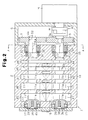
Fig. 2 is a cross-sectional plan view showing the Roots pump ofFig. 1 ; -
Fig. 3 is a cross-sectional view taken along line A-A inFig. 2 ; -
Fig. 4 is a perspective view showing a state in which two rear bearings shown inFig. 2 support a drive shaft and a driven shaft so that the shafts are rotatable with respect to a lower housing member; -
Fig. 5 is a longitudinal cross-sectional view showing a shaft accommodation portion of the housing shown inFig. 1 ; -
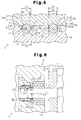
Fig. 6 is an enlarged longitudinal cross-sectional view showing a rear seal accommodation portion according to a second embodiment of the present invention; -
Fig. 7 is a cross-sectional plan view showing the rear seal accommodation portion ofFig. 6 ; -
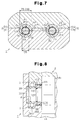
Fig. 8 is an enlarged longitudinal cross-sectional view showing a front seal accommodation portion according to the second embodiment; -
Fig. 9 is a cross-sectional plan view showing the front seal accommodation portion ofFig. 8 ; and -
Fig. 10 is a cross-sectional plan view showing a lower shaft accommodation portion of a modification. - A first embodiment which applies a fluid machine of the present invention into a Roots pump will be explained with reference to
Figs. 1 to 5 . The upper side inFig. 1 is referred to as the upper side of aRoots pump 1, and the lower side inFig. 1 is referred to as the lower side of theRoots pump 1. The left side inFig. 1 is referred to as the front side of the Roots pump 1, and the right side inFig. 1 is referred to as the rear side of theRoots pump 1. - As shown in
Figs. 1 and2 , ahousing 2 of the Roots pump 1 has alower housing member 10 and anupper housing member 20 that is joined to thelower housing member 10. Thehousing 2 has a two-piece structure. As shown inFig. 3 , an upper surface of thelower housing member 10 forms a flat lowerjoint surface 10a that contacts theupper housing member 20. One of the joint surfaces of the lower housing member is a continuous surface that contacts theupper housing member 20. The entire lowerjoint surface 10a is positioned on a same plane. That is, the height of any portions of the lowerjoint surface 10a is on a same plane with respect to the lower surface of thelower housing member 10, that is, a lowermost portion of thelower housing member 10. - Similarly, a lower surface of the
upper housing member 20 forms a flat upperjoint surface 20a that contacts thelower housing member 10. The entire upperjoint surface 20a is positioned on a same plane. The joint portion of the upperjoint surface 20a and the lowerjoint surface 10a forms ajoint portion 50 of thehousing 2. - The two-piece structure is a structure where the
upper housing member 20 is joined to thelower housing member 10 in a state where the lowerjoint surface 10a of thelower housing member 10 fully contacts the upperjoint surface 20a of theupper housing member 20 without having any steps. - As shown in
Fig. 2 ,front bearings housing 2 so as to be aligned with each other.Rear bearings housing 2 so as to be aligned with each other. Adrive shaft 3, which is a first rotary shaft, is inserted through thefront bearing 30 and therear bearing 32, each of which is a radial bearing. Similarly, a drivenshaft 4, which is a second rotary shaft, is inserted through thefront bearing 31 and therear bearing 33 each of which is a radial bearing. In other words, thefront bearing 30 and therear bearing 32 support thedrive shaft 3 rotatably with respect to thehousing 2. Similarly, thefront bearing 31 and therear bearing 33 support the drivenshaft 4 rotatably with respect to thehousing 2. Thedrive shaft 3 and the drivenshaft 4 are arranged in thehousing 2 so as to be parallel to each other. A first axis (center) P3 of thedrive shaft 3 is parallel to a second axis (center) P4 of the drivenshaft 4. The position of each movable wheel of thefront bearing positioning plate 39 with respect to the axes P3, P4. Thepositioning plate 39 is fixed by apositioning bolt 38 at each front end of thedrive shaft 3 and the drivenshaft 4. - As shown in
Figs. 1 and2 , the diameter of thedrive shaft 3 changes in steps. That is, thedrive shaft 3 has arear drive portion 3a, which is a small diameter drive portion having a small diameter D2, and afront drive portion 3b, which is a large diameter drive portion having a large diameter D3 (D2 < D3). The boundary between therear drive portion 3a and thefront drive portion 3b is positioned at the rear portion of thehousing 2. Similarly, the diameter of the drivenshaft 4 changes in steps. That is, the drivenshaft 4 has a rear drivenportion 4a, which is a driven small diameter portion having a small diameter D2, and a front drivenportion 4b, which is a driven large diameter having a large diameter D3 (D2 < D3). The boundary between the rear drivenportion 4a and the front drivenportion 4b is positioned at the rear portion of thehousing 2. -
Fig. 5 shows a cross-sectional plan view of the Roots pump 1 taken along a plane that is vertical to the first axis P3 and the second axis P4.Fig. 5 shows an imaginary plane H including the first axis P3 and the second axis P4. A portion that is above the imaginary plane H is referred to as an upper portion of the Roots pump 1, and a potion that is below the imaginary plane H is referred to as a lower portion of theRoots pump 1. A direction from one of thedrive shaft 3 and the drivenshaft 4 to the other is referred to as a width direction of theRoots pump 1. That is, the width direction of the Roots pump 1 is a direction parallel to the imaginary plane H and is a left-right direction inFig. 3 . In other words, the width direction of the Roots pump 1 is a direction along which thedrive shaft 3 and the drivenshaft 4 are aligned. - As shown in
Figs. 1 and2 , a plurality oflower wall pieces 11 are formed on thelower housing member 10 so as to extend toward theupper housing member 20. The sixlower wall pieces 11 are aligned along the axes P3, P4. Each of thelower wall pieces 11 has two lowershaft accommodation portions 11a, which are aligned along the width direction of theRoots pump 1. Each of the lowershaft accommodation portions 11a has a recess portion that accommodates thedrive shaft 3 or the drivenshaft 4. - As shown in
Fig. 5 , each lowershaft accommodation portion 11a has twostraight portions 111a and asemicircular portion 111b. Thesemicircular portion 111b is a portion of the lowershaft accommodation portion 11a that is below the axes P3, P4. Thesemicircular portion 111b has a semicircular shape that is formed along a peripheral surface of thedrive shaft 3 or the drivenshaft 4. Thesemicircular portion 111b accommodates a portion of thedrive shaft 3 or the drivenshaft 4 that is below the axes P3, P4. The twostraight portions 111a are portions of the lowershaft accommodation portion 11a that are above the axes P3, P4 and is formed in straight so as to extend up-down direction. Each of thestraight portions 111a extends vertically with respect to the lowerjoint surface 10a continuously from thesemicircular portion 111b. - The two
straight portions 111a face each other with respect to the width direction of theRoots pump 1. The twostraight portions 111a define ashaft insertion portion 111c therebetween. Thedrive shaft 3 or the drivenshaft 4 can be inserted to theshaft insertion portion 111c from above. - The width between the two
straight portions 111a, or an accommodation opening width T3 of the lowershaft accommodation portion 11a, is set to be greater than the large diameter D3 of thefront drive portion 3b and the front drivenportion 4b. In other words, the accommodation opening width T3 is set to be greater than the diameter (D3) of a portion of thedrive shaft 3 and the drivenshaft 4 that is accommodated in the lowershaft accommodation portion 11a. - As shown in
Figs. 1 and2 , two rear lowerseal accommodation portions 12 are recessed at the rear portion of thelower housing member 10. The two rear lowerseal accommodation portions 12 are arranged so as to be aligned along the width direction of theRoots pump 1. Each of the rear lowerseal accommodation portions 12 accommodates a first sealingmember 34. The rear lowerseal accommodation portion 12 is formed in an arc shown from a front side. - Two rear
lower support portions 13 are recessed at a rear side of the rear lowerseal accommodation portion 12 in the rear portion of thelower housing member 10. The two rearlower support portions 13 are arranged so as to be aligned along the width direction of theRoots pump 1. Each of the rearlower support portions 13 corresponds to a rear lower bearing support portion that supports the corresponding one of therear bearings lower support portion 13 is formed in an arc having a larger diameter than the rear lowerseal accommodation portion 12 as seen from a front side. Each of the rearlower support portions 13 accommodates asecond sealing member 35. Each second sealingmember 35 is located between the corresponding first sealingmember 34 and the corresponding one of therear bearings - For example, the first sealing
member 34 and the second sealingmember 35 are each one of or a combination of two or more of an oil seal, a mechanical seal, and an oil slinger. The steps formed between thefront drive portion 3b and therear drive portion 3a are located between the first sealingmember 34 and the second sealingmember 35. Similarly, the steps formed between the front drivenportion 4b and the rear drivenportion 4a are located between the first sealingmember 34 and the second sealingmember 35. Thefront drive portion 3b and the front drivenportion 4b correspond to (face) the first sealingmember 34 and the lowershaft accommodation portion 11a. Therear drive portion 3a and the rear drivenportion 4a each correspond to (face) one of thesecond sealing members 35 and the corresponding one of therear bearings - As shown in
Fig. 3 , opening edges (opening end portions) 13a, which are the uppermost portions of each rearlower support portion 13, are positioned above the centers P1 of therear bearings edges 13a corresponds to the opening width of the rearlower support portion 13, or a rear opening width T1, with respect to the width direction of theRoots pump 1. The rear opening width T1 is set to be smaller than the diameter D1 of therear bearings rear drive portion 3a and the rear drivenportion 4a (D2 < T1 < D1). In other words, the rear opening width T1 is set to be greater than the diameter (D2) of portions of thedrive shaft 3 and the drivenshaft 4 that are supported by therear bearings - Each rear
lower support portions 13 is formed in an arc having an angle greater than 180 degrees. That is, the portion of each rearlower support portion 13 that is above the centers P1 extends along an outer peripheral surface of the corresponding one of thebearings lower support portion 13 that is above the centers P1 protrudes toward the corresponding one of therear bearings lower support portion 13 extends to the lowerjoint surface 10a that is positioned above the imaginary plane H. - Similarly, as shown in
Figs. 1 and2 , two frontlower support portions 17 are recessed at the front end of thelower housing member 10. The two frontlower support portions 17 are arranged so as to be aligned with respect to the width direction of theRoots pump 1. Each of the frontlower support portions 17 corresponds to a front lower bearing support portion that supports the corresponding one of thefront bearings lower support portion 17 is formed in an arc as seen from a front side. The opening width of each frontlower support portion 17, or a front support opening width, with respect to the width direction of the Roots pump 1 is set in the same way as the rear opening width T1. That is, the front support opening width is formed to be smaller than the diameter of thefront bearings drive shaft 3 and the drivenshaft 4 that is supported by thefront bearings lower support portion 17 is also formed in an arc having an angle greater than 180 degrees. An upper end of each frontlower support portion 17 extends to the lowerjoint surface 10a that is positioned above the imaginary plane H. - As shown in
Fig. 1 , theupper housing member 20 has a plurality ofupper wall pieces 21 that contact thelower wall pieces 11. Each of theupper wall pieces 21 has two uppershaft accommodation portions 21a each of which corresponds to the lowershaft accommodation portion 11a. As shown inFig. 5 , each uppershaft accommodation portion 21a is formed in an arc having an angle smaller than 180 degrees as seen from the front side. Each uppershaft accommodation portion 21a covers a peripheral surface of a portion of thedrive shaft 3 or the drivenshaft 4 that protrudes upward from the lowerjoint surface 10a. The upper accommodation opening width T4, or an opening width of each uppershaft accommodation portion 21a, is set to be smaller than the diameter (D3) of a portion of thedrive shaft 3 and the drivenshaft 4 that is accommodated in the lowershaft accommodation portion 11a. The portions of theupper housing member 20 that accommodate thedrive shaft 3 or the drivenshaft 4 other than the uppershaft accommodation portions 21a are also formed in an arc like the uppershaft accommodation portions 21a. - As shown in
Fig. 1 , the rear portion of theupper housing member 20 has two rear upperseal accommodation portions 22 corresponding to the two rear lowerseal accommodation portions 12, respectively. Theupper housing member 20 has two rearupper support portions 23 that are located at a rear side of the rear upperseal accommodation portion 22. Each rearupper support portion 23 corresponds to one of thelower support portions 13. As shown inFig. 3 , an opening width T2 of each rearupper support portion 23 is same as the rear opening width T1. - The front portion of the
upper housing member 20 has two frontupper support portions 25 each of which corresponds to one of the frontlower support portions 17. An opening width of each frontupper support portion 25 is same as an opening width of each frontlower support portion 17. - As shown in
Fig. 1 , thelower wall pieces 11 and theupper wall pieces 21form end walls 60. The lowershaft accommodation portions 11a and the uppershaft accommodation portions 21a formshaft accommodation portions 83 that accommodate thedrive shaft 3 or the drivenshaft 4. Spaces formed between theadjacent end walls 60 along the axes P3, P4form pump chambers 70 to 74. The volume of each of thepump chambers 70 to 74 becomes smaller from thepump chamber 70, which is located at the front side, toward thepump chamber 74, which is located at the rear side. Thepump chamber 70 communicates with asuction port 24, which is formed at the upper front side of theupper housing member 20. Theadjacent pump chambers 70 to 74 communicate with each other through acommunication passage 75 that is formed in thelower wall piece 11. Thepump chamber 74 communicates with adischarge port 14, which is formed at the lower rear side of thelower housing member 10. Thedischarge port 14 is connected to adischarge mechanism 16 through aconnection muffler 15 and thedischarge mechanism 16 is connected to an exhaustgas treatment apparatus 29. - As shown in
Fig. 3 , thejoint portion 50 of thelower housing member 10 and theupper housing member 20 is located above the centers P1 of therear bearings joint portion 50 is set to be uniform in the entirejoint portion 50. Specifically, the height of thejoint portion 50 is located at a center between the centers P1 of therear bearings rear bearings - As shown in
Fig. 1 , each rear lowerseal accommodation portion 12 and the corresponding upperseal accommodation portion 22 form a rearseal accommodation portion 80 that accommodates the first sealingmember 34. Each frontlower support portion 17 and the corresponding frontupper support portion 25 form a frontbearing support portion 81. Each frontbearing support portion 81 contacts a whole peripheral surface of the corresponding one of thefront bearings front bearing - Each rear
lower support portion 13 and the corresponding rearupper support portion 23 form a rearbearing support portion 82. Each rearbearing support portion 82 forms a bearing accommodation zone that is greater than an outer size of therear bearing rear bearings bearing support portion 82 contacts a whole peripheral surface of the corresponding one of therear bearings rear bearing - As shown in
Fig. 2 , a plurality of (five) driverotors 40 to 44 are provided on thedrive shaft 3 so as to be integrally rotatable. The same number of drivenrotors 45 to 49 as thedrive rotors 40 to 44 are provided on the drivenshaft 4. As shown inFigs. 1 and2 , the thicknesses of thedrive rotors 40 to 44 and the thicknesses of the drivenrotors 45 to 49 decrease from the front side to the rear side. However, each of therotors 40 to 49 has a same shape and same size as seen from the direction of the axes P3, P4. As shown by broken lines of therotors Fig. 5 , the cross-sectional shape of each of therotors 40 to 49 that is vertical to the axes P3, P4 is formed in a shape of two lobes or formed in a shape of a gourd. In other words, each of therotors 40 to 49 has two lobe and recesses between the lobes. - As shown in
Fig. 2 , thedrive rotor 40 and the drivenrotor 45 have a predetermined phase difference therebetween and are accommodated in thepump chamber 70 so as to be engageable with each other. Similarly, therotors pump chamber 71, therotors pump chamber 72, therotors pump chamber 73 and therotors pump chamber 74. - As shown in
Fig. 5 , the minimum radial size of each of therotors 40 to 49 is referred to as a first measurement A. That is, the first measurement A represents the distance from the axes P3, P4 to the bottom of the recessed portion of eachrotor 40 to 49. In other words, the first measurement A represents the radial size of the thinnest portion of eachrotor 40 to 49 around theshaft shaft accommodation portion 11a is referred to as a second measurement B. That is, the second measurement B represents the distance from the axes P3, P4 to the boundary between thestraight portions 111a and the lowerjoint surface 10a. The first measurement A is set to be greater than the second measurement B. As a result, therotors 40 to 49 always closes a space that is created between thestraight portions 111a and the peripheral surface of thedrive shaft 3 or the drivenshaft 4 with respect to the axes P3, P4. The space is located inward of a rotation locus of therotors 40 to 49. This prevents the fluid from leaking from thepump chambers 70 to 74. - A portion of the
lower housing member 10 between therotors Fig. 2 ) also has straight portions, semicircular portions, and shaft insertion portions like the lowershaft accommodation portions 11a. Similarly, a portion of thelower housing member 10 between therotors front bearings lower housing member 10 other than the lowershaft accommodation portions 11a may have portions that accommodate thedrive shaft 3 and the drivenshaft 4, if necessary. Similarly, the portions ot theupper housing member 20 between therotors first sealing members 34 are formed in an arc like the uppershaft accommodation portion 21a. The portions of theupper housing member 20 between therotors front bearings shaft accommodation portion 21a. Each first sealingmember 34 does not contact therotor - As shown in
Figs. 1 and2 , agear housing 5 is assembled to the rear end of thehousing 2. Therear drive portion 3a and the rear drivenportion 4a protrude into thegear housing 5. Adrive gear 6 is engaged with therear drive portion 3a, and a drivengear 7 is engaged with the rear drivenportion 4a. In other words, thedrive gear 6 is engaged with the rear end of thedrive shaft 3, and the drivengear 7 is engaged with the rear end of the drivenshaft 4. Thedrive gear 6 and the drivengear 7 are meshed with each other to form a gear mechanism. Thedrive gear 6 and the drivengear 7 are timing gears that make timing to maintain the phase difference between thedrive rotors 40 to 44 and the drivenrotors 45 to 49 to be a predetermined value. - An electric motor M is attached to the
gear housing 5. A motor shaft M1 extending from the electric motor M is connected to thedrive shaft 3 via a joint 8, which is a shaft joint. Therefore, when the electric motor M rotates thedrive shaft 3, the drivenshaft 4 is rotated synchronously with thedrive shaft 3. As a result, each of therotors 40 to 49 is rotated and fluid (gas) in thepump chambers 70 to 74 is transferred with pressure to the exhaustgas treatment apparatus 29 via thedischarge port 14, theconnection muffler 15 and thedischarge mechanism 16. - Next, an assembling method of the Roots pump 1 is explained.
- The
drive shaft 3 having thedrive rotors 40 to 44 and the drivenshaft 4 having the drivenrotors 45 to 49 are assembled to the lower housing member from above. Each of therotors 40 to 49 is arranged between thelower wall pieces 11. Thedrive shaft 3 and the drivenshaft 4 pass through theshaft insertion portions 111c to be accommodated in thesemicircular portions 111b. - Then, the
first sealing members 34, thesecond sealing members 35, and thebearings lower housing member 10 to be attached to thedrive shaft 3 and the drivenshaft 4, respectively (seeFig. 4 ). Accordingly, the rearlower support portions 13 suppress therear bearings rear bearings front bearings lower housing member 10 to be attached to thedrive shaft 3 and the drivenshaft 4. Accordingly, the frontlower support portions 17 suppress thefront bearings front bearings - Next, clearances between the
drive rotors 40 to 44 and the drivenrotors 45 to 49 are measured and adjusted. One of thedrive rotors 40 to 44 and one of the drivenrotors 45 to 49 are selected. The clearance between each selected rotor and the correspondinglower wall piece 11 is measured by a clearance gauge to adjust the clearance. Measurement and adjustment of the clearance is repeated until an appropriate clearance is obtained. Since thedrive rotors 40 to 44 are engaged with thedrive shaft 3 and the drivenrotors 45 to 49 are engaged with the drivenshaft 4, the clearance between each of the other rotors and the correspondinglower wall piece 11 becomes an appropriate size when the clearance between each of the selected rotors and the correspondinglower wall piece 11 is adjusted to be an appropriate size. - After the clearances are adjusted, a fastener such as a C clip or a snap ring (not shown) is attached to an end surface of each of the
rear bearings rear bearings drive shaft 3, and the drivenshaft 4 with respect to the axes P3, P4. - Then, one pair of the rotors are selected from the
drive rotors 40 to 44 and the drivenrotors 45 to 49 and the phase difference between the selected rotors is adjusted. Since thedrive rotors 40 to 44 are arranged integrally with thedrive shaft 3, the phase difference between the other pairs of rotors is simultaneously adjusted when the phase difference between the selected pair of rotors is adjusted. - Then, the
drive gear 6 is engaged with therear drive portion 3a and the drivengear 7 is engaged with the rear drivenportion 4a such that thedrive gear 6 is engaged with the drivengear 7. At this time, the upward force may act on thebearings 30 to 33. However, the rearlower support portions 13 and the frontlower support portions 17 suppress thebearings 30 to 33 from being lifted from thelower housing member 10. - Then, the
upper housing member 20 is joined to thelower housing member 10 by bolts. That is, the bolts (not shown) are inserted through the insertion holes (not shown) of theupper housing member 20 to screw the bolts to screw holes (not shown) formed in thelower housing member 10. Then, therear drive portion 3a is connected to the motor shaft M1 via thejoint 8. Accordingly, the assembling operation of the Roots pump 1 is completed. - The first embodiment has driven advantages.
- (1) The opening edges 13a of each rear
lower support portion 13 are located above the centers P1 of therear bearings lower support portion 13 is smaller than the diameter D1 of therear bearings lower support portion 17 are also located above the centers of thefront bearings lower support portion 17 is smaller than the diameter of thefront bearings
Therefore, in a state where thedrive shaft 3, the drivenshaft 4, and thebearings 30 to 33 are mounted to thelower housing member 10, the opening edges 13a of the rearlower support portions 13 suppress therear bearings lower support portions 17 suppress thefront bearings bearings 30 to 33 are suppressed from being separated from thelower housing member 10. In other words, theupper housing member 20 is prevented from being assembled to thelower housing member 10 in a state where thebearings 30 to 33 are separated from thelower support portions rotors 40 to 49 that are engaged to each other is prevented from being adjusted in a state where thebearings 30 to 33 are separated from thelower support portions upper housing member 20 is prevented from being assembled to thelower housing member 10 in a state where the phase difference between the two of therotors 40 to 49 is offset. Since the unnecessary movement of thebearings 30 to 33 is prevented, the adjusted clearance between each of therotors 40 to 49 and thelower wall piece 11 is prevented from being changed. - (2) The
drive shaft 3, the drivenshaft 4, thebearings 30 to 33, and therotors 40 to 49 are exposed to the outside from the lowerjoint surface 10a in a state where they are mounted to the lower housing member 10 (seeFig. 4 ). Therefore, all the clearances between each of therotors 40 to 49 and thelower wall pieces 11 can be measured. Further, all the phase differences between therotors 40 to 49 can be visually recognized. Even if theupper housing member 20 is assembled to thelower housing member 10, the positions of thebearings 30 to 33 are not changed. Therefore, the adjusted clearance or phase difference is not changed and is maintained to be an appropriate value. Thedrive shaft 3, the drivenshaft 4, thebearings 30 to 33, and therotors 40 to 49 are exposed to the outside from the lowerjoint surface 10a only by removing theupper housing member 20 from thelower housing member 10. Therefore, even if the clearance or the phase difference is changed after the assembling of thehousing 2, it is easily adjusted again. - (3) The whole area of the lower
joint surface 10a, which contacts theupper housing member 20 is positioned in a single plane. Therefore, steps do not need to be formed on the lowerjoint surface 10a of thelower housing member 10. This permits thehousing 2 to be manufactured easily. - (4) For example, when the lower
joint surface 10a has steps, the upperjoint surface 20a is joined to the lowerjoint surface 10a after the steps corresponding to the lowerjoint surface 10a are formed. If the lowerjoint surface 10a and the upperjoint surface 20a have a dimensional tolerance, a space is likely to be created at thejoint portion 50 between the lowerjoint surface 10a and the upperjoint surface 20a. This may deteriorate the sealing property of thejoint portion 50. However, since the lowerjoint surface 10a of the present embodiment is entirely flat, the upperjoint surface 20a contacts the lowerjoint surface 10a without a gap. This improves the sealing property of thejoint portion 50. - (5) The rear opening width T1 of each rear
lower support portion 13 with respect to the width direction of the Roots pump 1 is set to be smaller than the diameter D1 of therear bearings drive shaft 3 and the drivenshaft 4 that are supported by therear bearing 32, 33 (D2 < T1 < D1). Similarly, the opening width of each frontlower support portion 17 with respect to the width direction of the Roots pump 1 is set to be smaller than the diameter of thefront bearings drive shaft 3 and the drivenshaft 4 that are supported by thefront bearings bearings 30 to 33 are suppressed from being separated from thelower housing member 10. Further, thedrive shaft 3 and the drivenshaft 4 can be assembled to thelower housing member 10 from above. - (6) The Roots pump 1 has the
drive shaft 3 and the drivenshaft 4. Thedrive shaft 3 and the drivenshaft 4 are rotated synchronously with each other by the meshing of thedrive gear 6 and the drivengear 7, which are timing gears. When thedrive gear 6 is meshed with the drivengear 7, therear bearings lower housing member 10. However, since the opening edges 13a of the rearlower support portions 13 suppress therear bearings rear bearings - (7) Each lower
shaft accommodation portion 11a has theshaft insertion portion 111c. The accommodation opening width T3 of theshaft insertion portion 111c is set to be greater than the diameter (D3) of the portions of thedrive shaft 3 and the drivenshaft 4 that are accommodated in the lowershaft accommodation portions 11a. Therefore, thedrive shaft 3 and the drivenshaft 4 can be assembled to thelower housing member 10 from above by inserting thedrive shaft 3 and the drivenshaft 4 into the lowershaft accommodation portions 11a. Accordingly, thedrive shaft 3 and the drivenshaft 4 are easily mounted to thelower housing member 10. - Next, a second embodiment of the present invention will be explained with reference to
Figs. 6 to 9 . Thefirst sealing member 34 and the second sealingmember 35 of the first embodiment are modified in the second embodiment. Like or the same reference numerals are given to those components that are like or the same as the corresponding components of the first embodiment, and detailed explanations are omitted. - As shown in
Figs. 6 and7 , each lowerseal accommodation portion 12 has an arc that has an angle greater than 180 degrees. That is, openingedges 12a, which are the uppermost portions of each rear lowerseal accommodation portion 12, are located above the axes P3, P4. In other words, the opening edges 12a extend to the lowerjoint surface 10a, which is above the imaginary plane H. - The rear opening width T5 with respect to the width direction of the Roots pump 1 is set to be greater than the diameter (D5) of the portions of the
drive shaft 3 and the drivenshaft 4 that are arranged in the rearseal accommodation portion 80. That is, the rear opening width T5, which is the width between two openingedges 12a, is greater than the diameter D5. The diameter (D5) of the portion of thedrive shaft 3 and the drivenshaft 4 that is arranged in the rearseal accommodation portion 80 can be set to be smaller than the diameter D3 or D2 of the first embodiment. - Each
shaft insertion portion 12b is defined between the corresponding pair of the openingedges 12a. Thedrive shaft 3 and the drivenshaft 4 can be inserted to the rear lowerseal accommodation portions 12 from above by passing through theshaft insertion portions 12b. A cylindricalrear sealing member 90 is accommodated in each rear lowerseal accommodation portion 12. Therear sealing members 90 are attached to thedrive shaft 3 and the drivenshaft 4. Eachrear sealing member 90 seals a space between thedrive shaft 3 or the drivenshaft 4 and the corresponding rearseal accommodation portion 80. - The inner surface of each rear upper
seal accommodation portion 22 is formed in an arc as seen from the front side. Each rear upperseal accommodation portion 22 is formed in an arc so as to cover the peripheral surface of therear sealing member 90 that protrudes upward from the lowerjoint surface 10a. The opening width T6 of the rear upperseal accommodation portion 22 is set to be the same as the rear opening width T5. - As shown in
Figs. 6 and7 , an annular space exists between the inner peripheral surface of each rearseal accommodation portion 80 and the peripheral surface of thedrive shaft 3 or the drivenshaft 4. Therear sealing members 90 are arranged in the spaces. Therear sealing members 90 are formed of a synthetic resin material. Therear sealing members 90 is fitted to thedrive shaft 3 and the drivenshaft 4 so as to be rotated integrally with thedrive shaft 3 and the drivenshaft 4. - As shown in
Fig. 6 , the front end surface of each rear sealingmember 90 closely contacts the rear end surface of the correspondingrotor rear O ring 99 is arranged between the inner peripheral surface of each rear sealingmember 90 and the peripheral surface of thedrive shaft 3 or the drivenshaft 4. - As shown in
Fig. 6 , arear spiral groove 91 is formed on an outer peripheral surface of each rear sealingmember 90 at a portion close to therear bearing rear spiral grooves 91 have a pumping operation for transporting fluid and lubricating oil contained in the fluid from thepump chamber 74 to therear bearings drive shaft 3 and the drivenshaft 4 are rotated. As a result, the lubricating oil is easily supplied to therear bearings drive gear 6, and the drivengear 7. That is, therear spiral grooves 91 have a pumping function for transporting the lubricating oil between the outer peripheral surfaces of therear sealing members 90 and the inner peripheral surface of the rearseal accommodation portions 80 to therear bearings spiral grooves 91 are shifted from therear bearings pump chamber 74 along the rotational directions of thedrive shaft 3 and the drivenshaft 4. - Two rear seal rings 93 are arranged on the outer peripheral surface of each rear sealing
member 90 at a portion close to thepump chamber 74. The rear seal rings 93 seal a space between the inner peripheral surface of each rearseal accommodation portion 80 and the outer peripheral surface of the correspondingrear sealing member 90. - As shown in
Figs. 6 and7 , anoil slinger 94 is arranged between each rear sealingmember 90 and the correspondingrear bearing shim 95 is arranged between theoil slinger 94 and therear bearing shim 95 maintains the adjusted clearance between each of therotors 40 to 49 and thelower wall pieces 11. - As shown in
Figs. 8 and9 , two frontseal accommodation portions 84 are formed at the front portion of thehousing 2 between each frontbearing support portion 81 and each of therotors seal accommodation portions 84 that are aligned along the width direction of the Roots pump 1 is formed to be a circular hole. - As shown in
Fig. 9 , each frontseal accommodation portion 84 has a front lowerseal accommodation portion 86 formed in thelower housing member 10 and a front upperseal accommodation portion 87 formed in theupper housing member 20. The front opening width T7 of each front lowerseal accommodation portion 86 with respect to the width direction of the Roots pump 1 is set to be greater than the diameter (D7) of the portions of thedrive shaft 3 and the drivenshaft 4 that is arranged are the frontseal accommodation portions 84. The opening edges 86a, which are the uppermost portions of each front lowerseal accommodation portion 86, are above the center of afront sealing member 100 and above the axes P3, P4. - Each front lower
seal accommodation portion 86 has an arc having an angle greater than 180 degrees. Ashaft insertion portion 86b is defined between each facing pair of the openingedges 86a. Thedrive shaft 3 and the drivenshaft 4 pass through theshaft insertion portions 86b to be inserted to the lowerseal accommodation portions 86 from above. Each front lowerseal accommodation portion 86 accommodates the cylindricalfront sealing member 100. - Each front upper
seal accommodation portion 87 is formed in an arc along the peripheral surface of the front sealingmember 100. The opening width T8 of each front upperseal accommodation portion 87 is set to be the same as the front opening width T7. - As shown in
Figs. 8 and9 , each front sealingmember 100 seals a space between the inner peripheral surface of the corresponding frontseal accommodation portion 84 and the peripheral surface of the corresponding one of thedrive shaft 3 and the drivenshaft 4. Thefront sealing members 100 made of a synthetic resin material are fitted to thedrive shaft 3 and the drivenshaft 4 so as to be rotated integrally with thedrive shaft 3 and the drivenshaft 4. - As shown in
Fig. 8 , the rear end surface of each front sealingmember 100 closely contacts the front end surface of the correspondingrotor Fig. 8 , afront O ring 101 is arranged in a portion between the inner peripheral surface of each front sealingmember 100 and the peripheral surface of the corresponding one of thedrive shaft 3 and the drivenshaft 4. Thefront O ring 101 seals a space between the peripheral surface of eachshaft member 100. - As shown in
Fig. 8 , on the outer peripheral surface of each front sealingmember 100, alabyrinth seal 102 is formed in a portion that is close to thefront bearing pump chamber 70. Eachfront seal ring 103 seals a space between the inner peripheral surface of the corresponding frontseal accommodation portion 84 and the outer peripheral surface of the correspondingfront sealing member 100. - Next, an assembling method of the Roots pump 1 according to the second embodiment will be explained.
- The
drive shaft 3 having thedrive rotors 40 to 44 and the drivenshaft 4 having the drivenrotors 45 to 49 are inserted to thelower housing member 10 from above. In this state, therear sealing members 90, theoil slingers 94, theshims 95, and therear bearings lower housing member 10 in this order to be attached to thedrive shaft 3 and the drivenshaft 4. Therear sealing members 90 are closely fitted to thedrive shaft 3 and the drivenshaft 4 so as to be rotated integrally therewith. Then, therear bearings lower support portion 13. Therear bearings step portions 10d formed between the rear lowerseal accommodation portions 12 and the rearlower support portions 13. - The
front sealing member 100 are attached to thedrive shaft 3 and the drivenshaft 4 from the front side of thelower housing member 10. Thefront sealing members 100 are closely fitted to thedrive shaft 3 and the drivenshaft 4 so as to be rotated integrally therewith. Thefront bearings lower support portions 17. Thefront bearings front sealing members 100. - Next, the clearance between each of the
rotors 40 to 49 and the correspondinglower wall piece 11 is measured and adjusted to an appropriate size. Then, theshims 95 are adjusted. Thereafter, thedrive gear 6 and the drivengear 7 are engaged with thedrive shaft 3 and the drivenshaft 4 such that theupper housing member 20 is joined to thelower housing member 10. - The second embodiment has the following advantage in addition to the advantages (1) to (7) of the first embodiment.
- (8) The diameters (D5, D7) of the
drive shaft 3 and the drivenshaft 4 are set to be smaller than the opening widths T5, T7 of the lowerseal accommodation portions drive shaft 3 and the drivenshaft 4 can be inserted to theseal accommodation portions edges seal accommodation portions members member seal accommodation portion drive shaft 3 or the drivenshaft 4. Therefore, the straight portions (see 111a) for inserting thedrive shaft 3 and the drivenshaft 4 are deleted from the corresponding portion of thelower housing member 10 between thefront bearing 30 and thedrive rotor 40, between thefront bearing 31 and the drivenrotor 45, between therear bearing 32 and thedrive rotor 44, and between therear bearing 33 and the drivenrotor 49. Accordingly, the space between one of the peripheral surfaces of the first rotary shaft and the drivenshaft 4, and the corresponding one of the inner peripheral surfaces of theseal accommodation portions - Each of the above embodiments is not limited thereto but may be modified as follows.
- The height of the uppermost portion of the
lower housing member 10, that is, the height of the opening edges 13a of eachlower support portion bearing lower support portion drive shaft 3 and the drivenshaft 4. For example, the height of the openingedges 13a may be set above or below the center between the center P1 of therear bearings rear bearings - The height of the portion of the
lower housing member 10 other than the opening edges 13a of thelower support portions front bearings rear bearings lower support portion bearings 30 to 33. The height of the upper surface of thelower wall piece 11 may be set to be the same as the axes P3, P4. By extending theupper wall pieces 21 to contact thelower wall piece 11, fluid leakage between theadjacent pump chambers 70 to 74 is suppressed. The height of only the opening edges of each lowershaft accommodation portion 11a, which are the upper ends of the lowershaft accommodation portion 11a, may be set to be the same as the axes P3, P4. That is, the height of only the portion of the lowerjoint surface 10a corresponding to the lowershaft accommodation portions 11a may be set to be the same as the axes P3, P4. In this case, the space between each lowershaft accommodation portion 11a and thedrive shaft 3 or the drivenshaft 4 may be reduced. This easily suppresses fluid that is transported by therotors 40 to 49 from passing through the space between the lowershaft accommodation portions 11a and the peripheral surface of thedrive shaft 3 or the drivenshaft 4 and leaking therefrom. - As long as the rear opening width T1 of the rear
lower support portions 13 is smaller than the diameter D1 of therear bearings bearing support portions 82 may be deformed so as to correspond to the outer shape of therear bearings upper support portions 23 may be set to be smaller than that of the arc of the rearlower support portions 13. - The size and the shape of each
pump chamber 70 to 74 may be changed according to the size and the shape of eachrotor 40 to 49. - The present invention may be applied to a fluid machine other than the Roots pump 1, for example, a screw pump or a claw pump. The fluid machine may be any machine that transports fluid by rotation of the
drive shaft 3 and the drivenshaft 4 having therotors 40 to 49. - As shown in
Fig. 10 , each lowershaft accommodation portion 11a may have enlargingportions 111e instead of thestraight portions 111a. The enlargingportions 111e increases the width of the lowershaft accommodation portion 11a gradually from thesemicircular portion 111b toward the lowerjoint surface 10a. That is, the accommodation open width T3 of each lowershaft accommodation portion 11a may be greater than the diameter (D3) of thedrive shaft 3 and the drivenshaft 4 with respect to the width direction of theRoots pump 1. Thedrive shaft 3 or the drivenshaft 4 can be inserted to the lowershaft accommodation portion 11a. Theshaft insertion portion 111c is defined between the two facing enlargingportions 111e. - As shown in
Fig. 10 , a second measurement B represents the distance from the axes P3, P4 to the boundary between each enlargingportion 111e and the lowerjoint surface 10a. The first measurement A may be shorter than the second measurement B. In this case, a disk-like seal plate 85 is integrally provided on thedrive shaft 3 and the drivenshaft 4 respectively so as to suppress fluid leakage from the space between each of therotors 40 to 49 and the enlargingportion 111e. Eachseal plate 85 is provided between each of therotors 40 to 49 and thelower wall pieces 11. A radius of theseal plate 85 is longer than the first measurement A and the second measurement B. - The sealing
members drive shaft 3 or the drivenshaft 4, but may be fixed to the inner peripheral surfaces of theseal accommodation portions - The
housing 2 does not need to have two rotary shafts, but may have only one rotary shaft. In this case, an upward force acts on the bearing when the bearing is press-fitted to the rearlower support portion 13. The rearlower support portion 13 suppresses the bearing from being separated. - The number of the pump chambers in the
housing 2 may be changed and may be one.
Claims (6)
- A fluid machine having a rotary shaft, a housing that supports the rotary shaft with a bearing, and a rotor that is provided on the rotary shaft, wherein the bearing is attached to the housing, and the rotor is rotated by rotation of the rotary shaft, and the machine transports fluid through rotation of the rotor,
wherein the housing has a two-piece structure having a lower housing member and an upper housing member that is joined to the lower housing member, wherein the lower housing member has a lower bearing support portion that is open upward, wherein the upper housing member has an upper bearing support portion that makes a pair with the lower bearing support portion, and the upper bearing support portion is open downward, wherein the lower bearing support portion and the upper bearing support portion support the bearing, wherein an uppermost portion of the lower bearing support portion is positioned above a center of the bearing, and an opening width of the lower bearing support portion is smaller than the diameter of the bearing. - The fluid machine according to claim 1, wherein the lower housing member has a joint surface that contacts the upper housing member, and the entire joint surface is positioned in a single plane.
- The fluid machine according to claim 1, wherein the lower housing member has a lower shaft accommodation portion that accommodates the rotary shaft and a joint surface that contacts the upper housing member, wherein the height of a portion of the joint surface that corresponds to at least the lower shaft accommodation portion is set to be the same as the height of an axis of the rotary shaft.
- The fluid machine according to any one of claims 1 to 3, wherein the lower housing member has a lower shaft accommodation portion that accommodates the rotary shaft, a shaft insertion portion is defined in the lower shaft accommodation portion, wherein the shaft insertion portion has an opening width that is greater than the diameter of a portion of the rotary shaft that is accommodated in the lower shaft accommodation portion.
- The fluid machine according to any one of claims 1 to 4, wherein the housing has a seal accommodation portion, and the seal accommodation portion accommodates a cylindrical sealing member that seals a space between an inner peripheral surface of the housing and a peripheral surface of the rotary shaft, and the seal accommodation portion has a lower seal accommodation portion that is formed in the lower housing member and an upper seal accommodation portion that is formed in the upper housing member, wherein the lower seal accommodation portion opens upward, and the upper seal accommodation portion makes a pair with the lower seal accommodation portion, wherein the upper seal accommodation portion opens downward, wherein a shaft insertion portion into which the rotary shaft is inserted is formed in the lower seal accommodation portion, and the shaft insertion portion has an opening width that is greater than the diameter of a portion of the rotary shaft that is accommodated in the seal accommodation portion.
- The fluid machine according to any one of claims 1 to 5, wherein the rotary shaft is one of a drive shaft and a driven shaft that are aligned so as to be parallel to each other in the housing, wherein a drive gear provided on the drive shaft is meshed with a driven gear that is provided on the driven shaft, and rotation of the drive shaft is transmitted from the drive gear to the driven gear so that the driven shaft is rotated synchronously with the drive shaft, and accordingly a drive rotor that is provided on the drive shaft and a driven rotor that is provided on the driven shaft are engaged to each other so as to be rotatable.
Applications Claiming Priority (2)
| Application Number | Priority Date | Filing Date | Title |
|---|---|---|---|
| JP2006196743 | 2006-07-19 | ||
| PCT/JP2007/064221 WO2008010539A1 (en) | 2006-07-19 | 2007-07-19 | Fluid machine |
Publications (3)
| Publication Number | Publication Date |
|---|---|
| EP2042742A1 true EP2042742A1 (en) | 2009-04-01 |
| EP2042742A4 EP2042742A4 (en) | 2013-08-28 |
| EP2042742B1 EP2042742B1 (en) | 2015-09-09 |
Family
ID=38956871
Family Applications (1)
| Application Number | Title | Priority Date | Filing Date |
|---|---|---|---|
| EP07790975.2A Not-in-force EP2042742B1 (en) | 2006-07-19 | 2007-07-19 | Fluid machine |
Country Status (6)
| Country | Link |
|---|---|
| US (1) | US8215937B2 (en) |
| EP (1) | EP2042742B1 (en) |
| JP (1) | JP4935814B2 (en) |
| KR (1) | KR20090014394A (en) |
| TW (1) | TWI332549B (en) |
| WO (1) | WO2008010539A1 (en) |
Cited By (1)
| Publication number | Priority date | Publication date | Assignee | Title |
|---|---|---|---|---|
| DE102010012759A1 (en) * | 2010-03-25 | 2011-09-29 | Pfeiffer Vacuum Gmbh | Rotor for a vacuum pump |
Families Citing this family (9)
| Publication number | Priority date | Publication date | Assignee | Title |
|---|---|---|---|---|
| JP5121826B2 (en) * | 2007-06-13 | 2013-01-16 | 樫山工業株式会社 | Roots type pump and method for manufacturing roots type pump |
| AU2010257248A1 (en) * | 2010-11-30 | 2012-06-14 | Mitsubishi Heavy Industries, Ltd. | Hydraulic pump structure for wind turbine generator or tidal current generator and method of mounting hydraulic pump |
| CN110500275B (en) | 2019-09-23 | 2021-03-16 | 兑通真空技术(上海)有限公司 | Pump housing structure of triaxial multistage roots pump |
| CN110594156B (en) | 2019-09-23 | 2021-05-25 | 兑通真空技术(上海)有限公司 | Driving structure of three-axis multistage roots pump |
| CN210629269U (en) | 2019-09-23 | 2020-05-26 | 兑通真空技术(上海)有限公司 | Motor connection transmission structure of roots pump |
| CN110685912A (en) | 2019-10-10 | 2020-01-14 | 兑通真空技术(上海)有限公司 | Structure for connecting multi-shaft multi-stage roots pump rotors |
| KR102553043B1 (en) | 2021-10-28 | 2023-07-07 | (주)세인테크 | A gear pump capable of dispensing a fine flow |
| CN115992817A (en) * | 2023-03-02 | 2023-04-21 | 山东省章丘鼓风机股份有限公司 | Roots blower with three-stage segmented casing |
| GB2641534A (en) * | 2024-06-04 | 2025-12-10 | Edwards Ltd | Clamshell stator for a vacuum pump, vacuum pump and method of manufacture |
Family Cites Families (12)
| Publication number | Priority date | Publication date | Assignee | Title |
|---|---|---|---|---|
| JPH0389080A (en) * | 1989-08-30 | 1991-04-15 | Ebara Corp | Seal mechanism for vacuum pump lubricating oil |
| JPH03145594A (en) | 1989-10-30 | 1991-06-20 | Anlet Co Ltd | Cooling device for multi-stage root type vacuum pump |
| JP2537696B2 (en) * | 1990-09-21 | 1996-09-25 | 株式会社荏原製作所 | Multi-stage vacuum pump |
| JP3682998B2 (en) * | 1995-02-13 | 2005-08-17 | 日本精工株式会社 | Rolling bearing device |
| US6582129B2 (en) * | 1998-08-27 | 2003-06-24 | Minebea Kabushiki Kaisha | Compound bearing apparatus, and spindle motor and swing arm for hard disk drive means including such bearing apparatus |
| US6506038B2 (en) * | 2000-08-15 | 2003-01-14 | Thermo King Corporation | Wear-preventing and positioning device for a screw compressor |
| FR2813104B1 (en) * | 2000-08-21 | 2002-11-29 | Cit Alcatel | SEAL FOR VACUUM PUMP |
| JP2002257244A (en) * | 2001-02-28 | 2002-09-11 | Toyota Industries Corp | Shaft seal structure in vacuum pump |
| JP4747437B2 (en) * | 2001-05-08 | 2011-08-17 | 株式会社豊田自動織機 | Oil leakage prevention structure in vacuum pump |
| JP2002349490A (en) | 2001-05-22 | 2002-12-04 | Mitsubishi Heavy Ind Ltd | Casing structure of fluid machine |
| EP1609549B1 (en) * | 2003-03-31 | 2011-06-08 | NSK Ltd. | Spindel apparatus comprising a withdrawable subassembly |
| DE102006054609B4 (en) * | 2006-11-17 | 2015-05-07 | Leica Mikrosysteme Gmbh | Device for processing samples |
-
2007
- 2007-07-19 TW TW096126308A patent/TWI332549B/en not_active IP Right Cessation
- 2007-07-19 WO PCT/JP2007/064221 patent/WO2008010539A1/en not_active Ceased
- 2007-07-19 EP EP07790975.2A patent/EP2042742B1/en not_active Not-in-force
- 2007-07-19 US US12/373,924 patent/US8215937B2/en not_active Expired - Fee Related
- 2007-07-19 KR KR1020087031431A patent/KR20090014394A/en not_active Ceased
- 2007-07-19 JP JP2008525894A patent/JP4935814B2/en not_active Expired - Fee Related
Cited By (3)
| Publication number | Priority date | Publication date | Assignee | Title |
|---|---|---|---|---|
| DE102010012759A1 (en) * | 2010-03-25 | 2011-09-29 | Pfeiffer Vacuum Gmbh | Rotor for a vacuum pump |
| EP2375074A3 (en) * | 2010-03-25 | 2014-11-12 | Pfeiffer Vacuum GmbH | Rotor for a vacuum pump |
| DE102010012759B4 (en) | 2010-03-25 | 2018-06-21 | Pfeiffer Vacuum Gmbh | Rotor for a vacuum pump |
Also Published As
| Publication number | Publication date |
|---|---|
| US8215937B2 (en) | 2012-07-10 |
| KR20090014394A (en) | 2009-02-10 |
| TW200819635A (en) | 2008-05-01 |
| JPWO2008010539A1 (en) | 2009-12-17 |
| JP4935814B2 (en) | 2012-05-23 |
| US20100047104A1 (en) | 2010-02-25 |
| EP2042742A4 (en) | 2013-08-28 |
| TWI332549B (en) | 2010-11-01 |
| EP2042742B1 (en) | 2015-09-09 |
| WO2008010539A1 (en) | 2008-01-24 |
Similar Documents
| Publication | Publication Date | Title |
|---|---|---|
| EP2042742B1 (en) | Fluid machine | |
| EP1122437B1 (en) | Scroll compressor | |
| KR102027695B1 (en) | Scroll compressor | |
| EP2172652B1 (en) | Fluid machine | |
| JP5931689B2 (en) | Scroll compressor | |
| CN102257244A (en) | scroll compressor | |
| US20200102956A1 (en) | Motor operated compressor | |
| EP1750011A1 (en) | Screw rotor and screw type fluid machine | |
| JP5421223B2 (en) | Vane type compressor | |
| EP3555476B1 (en) | Pump sealing | |
| WO2019026340A1 (en) | Vacuum pump | |
| JP5164720B2 (en) | External gear pump | |
| US9200633B2 (en) | Scroll compressor with oldham ring having scroll-side keys and bearing-side keys | |
| JP2007187100A (en) | Screw type fluid machine | |
| JP6368268B2 (en) | Biaxial rotary pump and adjusting method thereof | |
| JP2020122451A (en) | Compressor | |
| CN111379701A (en) | Compressor with a compressor housing having a plurality of compressor blades | |
| JP2021161953A (en) | Compressor | |
| JP2021161960A (en) | Compressor | |
| JPH04303192A (en) | Scroll fluid machine | |
| KR19980703498A (en) | Volumetric Hydraulic Machine | |
| JP2016017460A (en) | Scroll compressor |
Legal Events
| Date | Code | Title | Description |
|---|---|---|---|
| PUAI | Public reference made under article 153(3) epc to a published international application that has entered the european phase |
Free format text: ORIGINAL CODE: 0009012 |
|
| 17P | Request for examination filed |
Effective date: 20081121 |
|
| AK | Designated contracting states |
Kind code of ref document: A1 Designated state(s): AT BE BG CH CY CZ DE DK EE ES FI FR GB GR HU IE IS IT LI LT LU LV MC MT NL PL PT RO SE SI SK TR |
|
| AX | Request for extension of the european patent |
Extension state: AL BA HR MK RS |
|
| DAX | Request for extension of the european patent (deleted) | ||
| A4 | Supplementary search report drawn up and despatched |
Effective date: 20130725 |
|
| RIC1 | Information provided on ipc code assigned before grant |
Ipc: F01C 1/12 20060101ALI20130719BHEP Ipc: F04C 18/08 20060101ALI20130719BHEP Ipc: F01C 19/12 20060101ALI20130719BHEP Ipc: F01C 11/00 20060101ALI20130719BHEP Ipc: F04C 18/18 20060101ALI20130719BHEP Ipc: F01C 21/10 20060101ALI20130719BHEP Ipc: F01C 1/08 20060101ALI20130719BHEP Ipc: F04C 29/00 20060101AFI20130719BHEP Ipc: F04C 18/12 20060101ALI20130719BHEP Ipc: F04C 23/00 20060101ALI20130719BHEP Ipc: F01C 21/02 20060101ALI20130719BHEP |
|
| GRAP | Despatch of communication of intention to grant a patent |
Free format text: ORIGINAL CODE: EPIDOSNIGR1 |
|
| RIC1 | Information provided on ipc code assigned before grant |
Ipc: F04C 18/18 20060101ALI20150129BHEP Ipc: F01C 11/00 20060101ALI20150129BHEP Ipc: F01C 21/10 20060101ALI20150129BHEP Ipc: F01C 1/08 20060101ALI20150129BHEP Ipc: F04C 23/00 20060101ALI20150129BHEP Ipc: F04C 18/12 20060101ALI20150129BHEP Ipc: F04C 18/08 20060101ALI20150129BHEP Ipc: F01C 1/12 20060101ALI20150129BHEP Ipc: F01C 19/12 20060101ALI20150129BHEP Ipc: F04C 29/00 20060101AFI20150129BHEP Ipc: F01C 21/02 20060101ALI20150129BHEP |
|
| INTG | Intention to grant announced |
Effective date: 20150224 |
|
| GRAS | Grant fee paid |
Free format text: ORIGINAL CODE: EPIDOSNIGR3 |
|
| GRAA | (expected) grant |
Free format text: ORIGINAL CODE: 0009210 |
|
| AK | Designated contracting states |
Kind code of ref document: B1 Designated state(s): AT BE BG CH CY CZ DE DK EE ES FI FR GB GR HU IE IS IT LI LT LU LV MC MT NL PL PT RO SE SI SK TR |
|
| REG | Reference to a national code |
Ref country code: GB Ref legal event code: FG4D |
|
| REG | Reference to a national code |
Ref country code: AT Ref legal event code: REF Ref document number: 748365 Country of ref document: AT Kind code of ref document: T Effective date: 20150915 Ref country code: CH Ref legal event code: EP |
|
| REG | Reference to a national code |
Ref country code: IE Ref legal event code: FG4D |
|
| REG | Reference to a national code |
Ref country code: DE Ref legal event code: R096 Ref document number: 602007043031 Country of ref document: DE |
|
| REG | Reference to a national code |
Ref country code: NL Ref legal event code: MP Effective date: 20150909 |
|
| PG25 | Lapsed in a contracting state [announced via postgrant information from national office to epo] |
Ref country code: FI Free format text: LAPSE BECAUSE OF FAILURE TO SUBMIT A TRANSLATION OF THE DESCRIPTION OR TO PAY THE FEE WITHIN THE PRESCRIBED TIME-LIMIT Effective date: 20150909 Ref country code: LT Free format text: LAPSE BECAUSE OF FAILURE TO SUBMIT A TRANSLATION OF THE DESCRIPTION OR TO PAY THE FEE WITHIN THE PRESCRIBED TIME-LIMIT Effective date: 20150909 Ref country code: GR Free format text: LAPSE BECAUSE OF FAILURE TO SUBMIT A TRANSLATION OF THE DESCRIPTION OR TO PAY THE FEE WITHIN THE PRESCRIBED TIME-LIMIT Effective date: 20151210 Ref country code: LV Free format text: LAPSE BECAUSE OF FAILURE TO SUBMIT A TRANSLATION OF THE DESCRIPTION OR TO PAY THE FEE WITHIN THE PRESCRIBED TIME-LIMIT Effective date: 20150909 |
|
| REG | Reference to a national code |
Ref country code: LT Ref legal event code: MG4D |
|
| REG | Reference to a national code |
Ref country code: AT Ref legal event code: MK05 Ref document number: 748365 Country of ref document: AT Kind code of ref document: T Effective date: 20150909 |
|
| PG25 | Lapsed in a contracting state [announced via postgrant information from national office to epo] |
Ref country code: SE Free format text: LAPSE BECAUSE OF FAILURE TO SUBMIT A TRANSLATION OF THE DESCRIPTION OR TO PAY THE FEE WITHIN THE PRESCRIBED TIME-LIMIT Effective date: 20150909 Ref country code: ES Free format text: LAPSE BECAUSE OF FAILURE TO SUBMIT A TRANSLATION OF THE DESCRIPTION OR TO PAY THE FEE WITHIN THE PRESCRIBED TIME-LIMIT Effective date: 20150909 |
|
| PG25 | Lapsed in a contracting state [announced via postgrant information from national office to epo] |
Ref country code: NL Free format text: LAPSE BECAUSE OF FAILURE TO SUBMIT A TRANSLATION OF THE DESCRIPTION OR TO PAY THE FEE WITHIN THE PRESCRIBED TIME-LIMIT Effective date: 20150909 |
|
| PG25 | Lapsed in a contracting state [announced via postgrant information from national office to epo] |
Ref country code: CZ Free format text: LAPSE BECAUSE OF FAILURE TO SUBMIT A TRANSLATION OF THE DESCRIPTION OR TO PAY THE FEE WITHIN THE PRESCRIBED TIME-LIMIT Effective date: 20150909 Ref country code: SK Free format text: LAPSE BECAUSE OF FAILURE TO SUBMIT A TRANSLATION OF THE DESCRIPTION OR TO PAY THE FEE WITHIN THE PRESCRIBED TIME-LIMIT Effective date: 20150909 Ref country code: EE Free format text: LAPSE BECAUSE OF FAILURE TO SUBMIT A TRANSLATION OF THE DESCRIPTION OR TO PAY THE FEE WITHIN THE PRESCRIBED TIME-LIMIT Effective date: 20150909 Ref country code: IS Free format text: LAPSE BECAUSE OF FAILURE TO SUBMIT A TRANSLATION OF THE DESCRIPTION OR TO PAY THE FEE WITHIN THE PRESCRIBED TIME-LIMIT Effective date: 20160109 Ref country code: IT Free format text: LAPSE BECAUSE OF FAILURE TO SUBMIT A TRANSLATION OF THE DESCRIPTION OR TO PAY THE FEE WITHIN THE PRESCRIBED TIME-LIMIT Effective date: 20150909 |
|
| PG25 | Lapsed in a contracting state [announced via postgrant information from national office to epo] |
Ref country code: PL Free format text: LAPSE BECAUSE OF FAILURE TO SUBMIT A TRANSLATION OF THE DESCRIPTION OR TO PAY THE FEE WITHIN THE PRESCRIBED TIME-LIMIT Effective date: 20150909 Ref country code: AT Free format text: LAPSE BECAUSE OF FAILURE TO SUBMIT A TRANSLATION OF THE DESCRIPTION OR TO PAY THE FEE WITHIN THE PRESCRIBED TIME-LIMIT Effective date: 20150909 Ref country code: RO Free format text: LAPSE BECAUSE OF FAILURE TO SUBMIT A TRANSLATION OF THE DESCRIPTION OR TO PAY THE FEE WITHIN THE PRESCRIBED TIME-LIMIT Effective date: 20150909 Ref country code: PT Free format text: LAPSE BECAUSE OF FAILURE TO SUBMIT A TRANSLATION OF THE DESCRIPTION OR TO PAY THE FEE WITHIN THE PRESCRIBED TIME-LIMIT Effective date: 20160111 |
|
| REG | Reference to a national code |
Ref country code: DE Ref legal event code: R097 Ref document number: 602007043031 Country of ref document: DE |
|
| PLBE | No opposition filed within time limit |
Free format text: ORIGINAL CODE: 0009261 |
|
| STAA | Information on the status of an ep patent application or granted ep patent |
Free format text: STATUS: NO OPPOSITION FILED WITHIN TIME LIMIT |
|
| 26N | No opposition filed |
Effective date: 20160610 |
|
| PG25 | Lapsed in a contracting state [announced via postgrant information from national office to epo] |
Ref country code: SI Free format text: LAPSE BECAUSE OF FAILURE TO SUBMIT A TRANSLATION OF THE DESCRIPTION OR TO PAY THE FEE WITHIN THE PRESCRIBED TIME-LIMIT Effective date: 20150909 Ref country code: DK Free format text: LAPSE BECAUSE OF FAILURE TO SUBMIT A TRANSLATION OF THE DESCRIPTION OR TO PAY THE FEE WITHIN THE PRESCRIBED TIME-LIMIT Effective date: 20150909 |
|
| PG25 | Lapsed in a contracting state [announced via postgrant information from national office to epo] |
Ref country code: BE Free format text: LAPSE BECAUSE OF FAILURE TO SUBMIT A TRANSLATION OF THE DESCRIPTION OR TO PAY THE FEE WITHIN THE PRESCRIBED TIME-LIMIT Effective date: 20150909 |
|
| REG | Reference to a national code |
Ref country code: CH Ref legal event code: PL |
|
| GBPC | Gb: european patent ceased through non-payment of renewal fee |
Effective date: 20160719 |
|
| PG25 | Lapsed in a contracting state [announced via postgrant information from national office to epo] |
Ref country code: MC Free format text: LAPSE BECAUSE OF FAILURE TO SUBMIT A TRANSLATION OF THE DESCRIPTION OR TO PAY THE FEE WITHIN THE PRESCRIBED TIME-LIMIT Effective date: 20150909 |
|
| PG25 | Lapsed in a contracting state [announced via postgrant information from national office to epo] |
Ref country code: FR Free format text: LAPSE BECAUSE OF NON-PAYMENT OF DUE FEES Effective date: 20160801 Ref country code: CH Free format text: LAPSE BECAUSE OF NON-PAYMENT OF DUE FEES Effective date: 20160731 Ref country code: LI Free format text: LAPSE BECAUSE OF NON-PAYMENT OF DUE FEES Effective date: 20160731 |
|
| REG | Reference to a national code |
Ref country code: FR Ref legal event code: ST Effective date: 20170331 |
|
| REG | Reference to a national code |
Ref country code: IE Ref legal event code: MM4A |
|
| PG25 | Lapsed in a contracting state [announced via postgrant information from national office to epo] |
Ref country code: GB Free format text: LAPSE BECAUSE OF NON-PAYMENT OF DUE FEES Effective date: 20160719 |
|
| PG25 | Lapsed in a contracting state [announced via postgrant information from national office to epo] |
Ref country code: IE Free format text: LAPSE BECAUSE OF NON-PAYMENT OF DUE FEES Effective date: 20160719 |
|
| PG25 | Lapsed in a contracting state [announced via postgrant information from national office to epo] |
Ref country code: LU Free format text: LAPSE BECAUSE OF NON-PAYMENT OF DUE FEES Effective date: 20160719 |
|
| PG25 | Lapsed in a contracting state [announced via postgrant information from national office to epo] |
Ref country code: CY Free format text: LAPSE BECAUSE OF FAILURE TO SUBMIT A TRANSLATION OF THE DESCRIPTION OR TO PAY THE FEE WITHIN THE PRESCRIBED TIME-LIMIT Effective date: 20150909 Ref country code: HU Free format text: LAPSE BECAUSE OF FAILURE TO SUBMIT A TRANSLATION OF THE DESCRIPTION OR TO PAY THE FEE WITHIN THE PRESCRIBED TIME-LIMIT; INVALID AB INITIO Effective date: 20070719 |
|
| PG25 | Lapsed in a contracting state [announced via postgrant information from national office to epo] |
Ref country code: MT Free format text: LAPSE BECAUSE OF NON-PAYMENT OF DUE FEES Effective date: 20160731 Ref country code: TR Free format text: LAPSE BECAUSE OF FAILURE TO SUBMIT A TRANSLATION OF THE DESCRIPTION OR TO PAY THE FEE WITHIN THE PRESCRIBED TIME-LIMIT Effective date: 20150909 |
|
| PG25 | Lapsed in a contracting state [announced via postgrant information from national office to epo] |
Ref country code: BG Free format text: LAPSE BECAUSE OF FAILURE TO SUBMIT A TRANSLATION OF THE DESCRIPTION OR TO PAY THE FEE WITHIN THE PRESCRIBED TIME-LIMIT Effective date: 20150909 |
|
| PGFP | Annual fee paid to national office [announced via postgrant information from national office to epo] |
Ref country code: DE Payment date: 20190710 Year of fee payment: 13 |
|
| REG | Reference to a national code |
Ref country code: DE Ref legal event code: R119 Ref document number: 602007043031 Country of ref document: DE |
|
| PG25 | Lapsed in a contracting state [announced via postgrant information from national office to epo] |
Ref country code: DE Free format text: LAPSE BECAUSE OF NON-PAYMENT OF DUE FEES Effective date: 20210202 |