EP2042724A1 - Intake manifold for an internal combustion engine provided with metallic reinforcement brackets for fastening the fuel common rail - Google Patents
Intake manifold for an internal combustion engine provided with metallic reinforcement brackets for fastening the fuel common rail Download PDFInfo
- Publication number
- EP2042724A1 EP2042724A1 EP07425597A EP07425597A EP2042724A1 EP 2042724 A1 EP2042724 A1 EP 2042724A1 EP 07425597 A EP07425597 A EP 07425597A EP 07425597 A EP07425597 A EP 07425597A EP 2042724 A1 EP2042724 A1 EP 2042724A1
- Authority
- EP
- European Patent Office
- Prior art keywords
- fastening
- intake manifold
- central body
- hole
- common rail
- Prior art date
- Legal status (The legal status is an assumption and is not a legal conclusion. Google has not performed a legal analysis and makes no representation as to the accuracy of the status listed.)
- Withdrawn
Links
- 239000000446 fuel Substances 0.000 title claims abstract description 19
- 238000002485 combustion reaction Methods 0.000 title claims abstract description 18
- 230000002787 reinforcement Effects 0.000 title claims abstract description 14
- 238000004519 manufacturing process Methods 0.000 description 2
- 229910000831 Steel Inorganic materials 0.000 description 1
- XAGFODPZIPBFFR-UHFFFAOYSA-N aluminium Chemical compound [Al] XAGFODPZIPBFFR-UHFFFAOYSA-N 0.000 description 1
- 229910052782 aluminium Inorganic materials 0.000 description 1
- 239000004411 aluminium Substances 0.000 description 1
- 230000004048 modification Effects 0.000 description 1
- 238000012986 modification Methods 0.000 description 1
- 239000007787 solid Substances 0.000 description 1
- 230000002269 spontaneous effect Effects 0.000 description 1
- 239000010959 steel Substances 0.000 description 1
- 239000012815 thermoplastic material Substances 0.000 description 1
Images


Classifications
-
- F—MECHANICAL ENGINEERING; LIGHTING; HEATING; WEAPONS; BLASTING
- F02—COMBUSTION ENGINES; HOT-GAS OR COMBUSTION-PRODUCT ENGINE PLANTS
- F02M—SUPPLYING COMBUSTION ENGINES IN GENERAL WITH COMBUSTIBLE MIXTURES OR CONSTITUENTS THEREOF
- F02M35/00—Combustion-air cleaners, air intakes, intake silencers, or induction systems specially adapted for, or arranged on, internal-combustion engines
- F02M35/10—Air intakes; Induction systems
- F02M35/104—Intake manifolds
-
- F—MECHANICAL ENGINEERING; LIGHTING; HEATING; WEAPONS; BLASTING
- F02—COMBUSTION ENGINES; HOT-GAS OR COMBUSTION-PRODUCT ENGINE PLANTS
- F02M—SUPPLYING COMBUSTION ENGINES IN GENERAL WITH COMBUSTIBLE MIXTURES OR CONSTITUENTS THEREOF
- F02M35/00—Combustion-air cleaners, air intakes, intake silencers, or induction systems specially adapted for, or arranged on, internal-combustion engines
- F02M35/10—Air intakes; Induction systems
- F02M35/10209—Fluid connections to the air intake system; their arrangement of pipes, valves or the like
- F02M35/10216—Fuel injectors; Fuel pipes or rails; Fuel pumps or pressure regulators
-
- F—MECHANICAL ENGINEERING; LIGHTING; HEATING; WEAPONS; BLASTING
- F02—COMBUSTION ENGINES; HOT-GAS OR COMBUSTION-PRODUCT ENGINE PLANTS
- F02M—SUPPLYING COMBUSTION ENGINES IN GENERAL WITH COMBUSTIBLE MIXTURES OR CONSTITUENTS THEREOF
- F02M35/00—Combustion-air cleaners, air intakes, intake silencers, or induction systems specially adapted for, or arranged on, internal-combustion engines
- F02M35/10—Air intakes; Induction systems
- F02M35/10242—Devices or means connected to or integrated into air intakes; Air intakes combined with other engine or vehicle parts
-
- F—MECHANICAL ENGINEERING; LIGHTING; HEATING; WEAPONS; BLASTING
- F02—COMBUSTION ENGINES; HOT-GAS OR COMBUSTION-PRODUCT ENGINE PLANTS
- F02M—SUPPLYING COMBUSTION ENGINES IN GENERAL WITH COMBUSTIBLE MIXTURES OR CONSTITUENTS THEREOF
- F02M55/00—Fuel-injection apparatus characterised by their fuel conduits or their venting means; Arrangements of conduits between fuel tank and pump F02M37/00
- F02M55/02—Conduits between injection pumps and injectors, e.g. conduits between pump and common-rail or conduits between common-rail and injectors
- F02M55/025—Common rails
Definitions
- the present invention relates to an intake manifold for an internal combustion engine provided with metallic reinforcement brackets for fastening the fuel common rail.
- a low-pressure pump feeds the fuel from a tank to a high-pressure pump, which in turn feeds the fuel to a common rail.
- the common rail is adapted to contain the pressurized fuel for feeding the fuel itself to the injectors (one for each cylinder of the engine), which are cyclically driven to inject part of the pressurized fuel present in the common rail into the corresponding cylinders.
- the fuel pressure value within the common rail is constantly maintained equal to a desired value, which is generally variable as a function of the engine point and in modern engines is very high (even higher than 2000 bars).
- the common rails are very heavy components formed by forged steel.
- the common rail is directly fastened either to the crankcase or to the engine head, i.e. at the metallic parts of the engine by means of fastening screws; alternatively, the common rail may be fastened directly to the intake manifold formed by aluminium by means of the fastening screws.
- the intake manifold is formed by thermoplastic material
- the common rail must necessarily be fastened either to the crankcase or to the engine head because the intake manifold is not sufficiently rigid to support the common rail and withstand the vibrations which are caused by the engine and by the tensions which are induced by the delivery pipes which connect the common rail to the injectors and by the feeding tubes which connect the common rail to the high pressure pump.
- an intake manifold for an internal combustion engine provided with metallic reinforcement brackets for fastening the fuel common rail as claimed in the accompanying claims.
- numeral 1 indicates as a whole an internal combustion engine which comprises an engine head in which a number of cylinders (not shown) are obtained and a common rail 2 which receives the pressurized fuel and is connected to a number of injectors (not shown), each of which injects the fuel into a corresponding cylinder.
- the internal combustion engine 1 further comprises a common intake manifold 3, which comprises in turn a central body 4 and conduits.
- a central body 4 In the central body 4, there is obtained an intake chamber 5 which receives the intake air, while each conduit is adapted to connect the intake chamber 5 to a corresponding cylinder of the internal combustion engine 1.
- the intake manifold 3 comprises first passage through holes 6, which are obtained in the central body 4 of the intake manifold 3 to allow the fastening of the intake manifold 3 itself to the engine head by means of the first fastening screws 7 which are screwed into the engine head.
- first fastening screws 7 which are screwed into the engine head.
- first assembly hole 13 In each first assembly hole 13, there is inserted a corresponding metallic bushing 8.
- the intake manifold 3 further comprises second blank, threaded fastening holes 9, which are obtained in the central body 4 of the intake manifold 3 to allow the fastening of the common rail 2 to the central body 4 itself by means of second fastening screws 10 which are screwed onto the central body 4.
- second fastening screws 10 which are screwed onto the central body 4.
- each assembly hole 14 there is embedded a corresponding threaded metallic boss 11 which is co-pressed along with the central body 4.
- the intake manifold 3 comprises a metallic reinforcement bracket 12 for each second fastening hole 9.
- the metallic reinforcement bracket 12 presents a first through assembly hole 13 arranged over and coaxially to a corresponding first fastening hole 6 in order to be locked onto the central body 4 by the corresponding first fastening screw 7 and a second assembly through hole 14 arranged over and coaxially to a corresponding second fastening hole 9 in order to be locked onto the central body 4 by the corresponding second fastening screw 10.
- a second embodiment contemplates that the metallic reinforcement bracket 12 comprises a first assembly through hole 13 arranged over and coaxially to a corresponding first fastening hole 6 in order to be locked onto the central body 4 by the corresponding first fastening screw 7 and two second assembly through holes 14 arranged over and coaxially to corresponding fastening holes 9 in order to be locked onto the central body 4 by two corresponding second fastening screws 10.
- each metallic reinforcement bracket 12 is "L"-shaped and thus comprises a first part 15 which presents the first assembly hole 13 and a second part 16 which presents the second assembly hole 14 which are reciprocally perpendicular.
- the above-described intake manifold 3 for an internal combustion engine 1 has many advantages because it is simple and cost-effective and above all allows to obtain a solid, robust structure. Furthermore, the structure which is obtained is very compact as it allows to reduce the distance between the fuel common rail 2 and the engine head by using shorter, simpler shaped delivery pipes which connect the common rail 2 to the injectors with low manufacturing and assembly costs and with low load loss.
Landscapes
- Engineering & Computer Science (AREA)
- Chemical & Material Sciences (AREA)
- Combustion & Propulsion (AREA)
- Mechanical Engineering (AREA)
- General Engineering & Computer Science (AREA)
- Fuel-Injection Apparatus (AREA)
Abstract
Description
- The present invention relates to an intake manifold for an internal combustion engine provided with metallic reinforcement brackets for fastening the fuel common rail.
- In current spontaneous ignition internal combustion engines (i.e. operating according to the "Diesel" cycle and fed with oil fuel or the like), a low-pressure pump feeds the fuel from a tank to a high-pressure pump, which in turn feeds the fuel to a common rail. The common rail is adapted to contain the pressurized fuel for feeding the fuel itself to the injectors (one for each cylinder of the engine), which are cyclically driven to inject part of the pressurized fuel present in the common rail into the corresponding cylinders. For the correct operation of the combustion, it is important for the fuel pressure value within the common rail to be constantly maintained equal to a desired value, which is generally variable as a function of the engine point and in modern engines is very high (even higher than 2000 bars). In order to work at such high pressure values, in this type of internal combustion engine, the common rails are very heavy components formed by forged steel.
- In current systems, the common rail is directly fastened either to the crankcase or to the engine head, i.e. at the metallic parts of the engine by means of fastening screws; alternatively, the common rail may be fastened directly to the intake manifold formed by aluminium by means of the fastening screws. If the intake manifold is formed by thermoplastic material, the common rail must necessarily be fastened either to the crankcase or to the engine head because the intake manifold is not sufficiently rigid to support the common rail and withstand the vibrations which are caused by the engine and by the tensions which are induced by the delivery pipes which connect the common rail to the injectors and by the feeding tubes which connect the common rail to the high pressure pump.
- However, fastening the common rail either to the crankcase or to the engine head has some drawbacks, as it forces to use longer and more complexly shaped delivery pipes which connect the common rail to the injectors with a consequent increase of manufacturing costs, assembly costs and load losses.
- It is the object of the present invention to provide an intake manifold for an internal combustion engine provided with metallic reinforcement brackets for fastening the fuel common rail, such a manifold being free from the above-described drawbacks and specifically being easy and cost-effective to implement and allowing to obtain a strong fastening with reduced interventions and modifications to the fixtures, such as for example the mould for the intake manifold.
- According to the present invention, there is provided an intake manifold for an internal combustion engine provided with metallic reinforcement brackets for fastening the fuel common rail as claimed in the accompanying claims.
- The present invention will now be described with reference to the accompanying drawings, which illustrate a non-limitative embodiment thereof, in which:
-
figure 1 is a diagrammatic view of an intake manifold for an internal combustion engine provided with metallic reinforcement brackets for supporting the fuel common rail according to the present invention; -
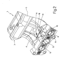
figure 2 shows a diagrammatic view of a different embodiment of the intake manifold for an internal combustion engine provided with metallic reinforcement brackets; -
figure 3 is a diagrammatic side elevation section view of an intake manifold for an internal combustion engine provided with metallic reinforcement brackets infigure 1 . - In
figure 1 , numeral 1 indicates as a whole an internal combustion engine which comprises an engine head in which a number of cylinders (not shown) are obtained and acommon rail 2 which receives the pressurized fuel and is connected to a number of injectors (not shown), each of which injects the fuel into a corresponding cylinder. - The internal combustion engine 1 further comprises a
common intake manifold 3, which comprises in turn acentral body 4 and conduits. In thecentral body 4, there is obtained anintake chamber 5 which receives the intake air, while each conduit is adapted to connect theintake chamber 5 to a corresponding cylinder of the internal combustion engine 1. - The
intake manifold 3 comprises first passage throughholes 6, which are obtained in thecentral body 4 of theintake manifold 3 to allow the fastening of theintake manifold 3 itself to the engine head by means of thefirst fastening screws 7 which are screwed into the engine head. In eachfirst assembly hole 13, there is inserted a correspondingmetallic bushing 8. - As shown in
figure 3 , theintake manifold 3 further comprises second blank, threadedfastening holes 9, which are obtained in thecentral body 4 of theintake manifold 3 to allow the fastening of thecommon rail 2 to thecentral body 4 itself by means of second fasteningscrews 10 which are screwed onto thecentral body 4. In eachassembly hole 14 there is embedded a corresponding threadedmetallic boss 11 which is co-pressed along with thecentral body 4. - As shown in
figure 1 and3 , theintake manifold 3 comprises ametallic reinforcement bracket 12 for eachsecond fastening hole 9. Themetallic reinforcement bracket 12 presents a first throughassembly hole 13 arranged over and coaxially to a correspondingfirst fastening hole 6 in order to be locked onto thecentral body 4 by the correspondingfirst fastening screw 7 and a second assembly throughhole 14 arranged over and coaxially to a correspondingsecond fastening hole 9 in order to be locked onto thecentral body 4 by the correspondingsecond fastening screw 10. As shown infigure 2 , a second embodiment contemplates that themetallic reinforcement bracket 12 comprises a first assembly throughhole 13 arranged over and coaxially to a correspondingfirst fastening hole 6 in order to be locked onto thecentral body 4 by the correspondingfirst fastening screw 7 and two second assembly throughholes 14 arranged over and coaxially to correspondingfastening holes 9 in order to be locked onto thecentral body 4 by two correspondingsecond fastening screws 10. - As shown in
figure 3 , eachmetallic reinforcement bracket 12 is "L"-shaped and thus comprises afirst part 15 which presents thefirst assembly hole 13 and asecond part 16 which presents thesecond assembly hole 14 which are reciprocally perpendicular. - The above-described
intake manifold 3 for an internal combustion engine 1 has many advantages because it is simple and cost-effective and above all allows to obtain a solid, robust structure. Furthermore, the structure which is obtained is very compact as it allows to reduce the distance between the fuelcommon rail 2 and the engine head by using shorter, simpler shaped delivery pipes which connect thecommon rail 2 to the injectors with low manufacturing and assembly costs and with low load loss.
Claims (5)
- An intake manifold (3) for an internal combustion engine (1) comprising an engine head in which a number of cylinders are obtained; the intake manifold (3) comprises:a central body (4), wherein there are obtained an intake chamber (5) which receives the intake air and a number of pipes each of which connects the chamber (5) to a corresponding cylinder of the internal combustion engine (1);first passage through holes (6) obtained in the central body (4) for fastening the intake manifold (3) to the engine head by means of first fastening screws (7) screwed into the engine head;a common rail (2) which receives the pressurized fuel and is connected to a number of injectors, each of which injects the fuel into a corresponding cylinder; andsecond blank threaded fastening holes (9) obtained in the central body (4) for fastening the common rail (2) to the central body (4) itself by means of the second fastening screws (10) screwed into the central body (4); the intake manifold (3) is characterized in that it comprises for each second fastening hole (9) a first metallic reinforcement bracket (12), which presents a first assembly through hole (13) arranged over and coaxially to a corresponding first fastening hole (6) in order to be locked onto the central body (4) by the corresponding first fastening screw (7) and a second assembly through hole (14) arranged over and coaxially to a corresponding second fastening hole (9) in order to be locked onto the central body (4) of the corresponding second fastening screw (10).
- An intake manifold (3) according to claim 1, wherein each metallic reinforcement bracket (12) is "L"-shaped and comprises a first part (15) which presents the first assembly hole (13) and a second part (16) which presents the second assembly hole (14) and is perpendicular to the first part (15).
- An intake manifold (3) according to claim 1 or 2, wherein a corresponding metallic bushing (8) is inserted in each first assembly hole (13).
- An intake manifold (3) according to claim 1, 2 or 3, wherein a corresponding threaded metallic boss (11) is embedded in each second assembly hole (14).
- An intake manifold (3) according to claim 4, wherein each threaded metallic boss (11) is co-pressed along with the central body (4).
Priority Applications (4)
| Application Number | Priority Date | Filing Date | Title |
|---|---|---|---|
| EP07425597A EP2042724A1 (en) | 2007-09-26 | 2007-09-26 | Intake manifold for an internal combustion engine provided with metallic reinforcement brackets for fastening the fuel common rail |
| BRPI0804177-6A BRPI0804177A2 (en) | 2007-09-26 | 2008-09-26 | manifold for an internal combustion engine fitted with metal reinforcing angle brackets for fixing the Community fuel distribution grille |
| US12/238,811 US8096277B2 (en) | 2007-09-26 | 2008-09-26 | Intake manifold for an internal combustion engine provided with metallic reinforcement brackets for fastening the fuel common rail |
| CN2008101674468A CN101429907B (en) | 2007-09-26 | 2008-09-26 | Intake manifold for an internal combustion engine provided with metallic reinforcement brackets for fastening the fuel common rail |
Applications Claiming Priority (1)
| Application Number | Priority Date | Filing Date | Title |
|---|---|---|---|
| EP07425597A EP2042724A1 (en) | 2007-09-26 | 2007-09-26 | Intake manifold for an internal combustion engine provided with metallic reinforcement brackets for fastening the fuel common rail |
Publications (1)
| Publication Number | Publication Date |
|---|---|
| EP2042724A1 true EP2042724A1 (en) | 2009-04-01 |
Family
ID=39003867
Family Applications (1)
| Application Number | Title | Priority Date | Filing Date |
|---|---|---|---|
| EP07425597A Withdrawn EP2042724A1 (en) | 2007-09-26 | 2007-09-26 | Intake manifold for an internal combustion engine provided with metallic reinforcement brackets for fastening the fuel common rail |
Country Status (4)
| Country | Link |
|---|---|
| US (1) | US8096277B2 (en) |
| EP (1) | EP2042724A1 (en) |
| CN (1) | CN101429907B (en) |
| BR (1) | BRPI0804177A2 (en) |
Cited By (1)
| Publication number | Priority date | Publication date | Assignee | Title |
|---|---|---|---|---|
| US20120298076A1 (en) * | 2009-09-22 | 2012-11-29 | Systems Moteurs | Functional module that integrates a distributor and a fuel rail and process for its production |
Families Citing this family (5)
| Publication number | Priority date | Publication date | Assignee | Title |
|---|---|---|---|---|
| JP6074135B2 (en) * | 2011-03-29 | 2017-02-01 | 現代自動車株式会社Hyundai Motor Company | Manufacturing method of intake manifold module for preventing automobile fuel leakage |
| EP2690281A1 (en) | 2012-07-23 | 2014-01-29 | Continental Automotive GmbH | Fuel rail assembly |
| US9377199B2 (en) | 2012-12-28 | 2016-06-28 | General Electric Company | Methods of reinforcing combustor aperture and related combustor |
| US10220700B2 (en) * | 2015-02-09 | 2019-03-05 | Toyota Motor Engineering & Manufacturing North America, Inc. | Protection and support for vehicle engine components |
| IT202300010650A1 (en) * | 2023-05-25 | 2024-11-25 | Fca Italy Spa | INTERNAL COMBUSTION ENGINE WITH OPTIMIZED INSTALLATION OF A FUEL TRANSIT MANIFOLD |
Citations (6)
| Publication number | Priority date | Publication date | Assignee | Title |
|---|---|---|---|---|
| EP0385820A1 (en) * | 1989-02-27 | 1990-09-05 | Automobiles Peugeot | Arrangement for sustaining and positioning several fuel injectors in an internal-combustion engine |
| EP0491582A1 (en) * | 1990-12-17 | 1992-06-24 | Automobiles Peugeot | Angular and elevational positioning arrangement for several fuel injection valves in an internal combustion engine |
| JPH06264844A (en) * | 1993-03-15 | 1994-09-20 | Nissan Motor Co Ltd | Mounting structure for fuel supply pipe of internal combustion engine |
| JPH07103104A (en) * | 1993-09-30 | 1995-04-18 | Suzuki Motor Corp | Mounting structure for fuel delivery pipe |
| JPH1018938A (en) * | 1996-06-28 | 1998-01-20 | Suzuki Motor Corp | Mounting device for synthetic resin fuel pipes |
| JP2002303224A (en) * | 2001-04-02 | 2002-10-18 | Denso Corp | Intake manifold module |
Family Cites Families (5)
| Publication number | Priority date | Publication date | Assignee | Title |
|---|---|---|---|---|
| US4104994A (en) * | 1976-09-01 | 1978-08-08 | Borg-Warner Corporation | Charge forming method and apparatus with accelerating system |
| JP3772483B2 (en) * | 1997-07-31 | 2006-05-10 | スズキ株式会社 | Support structure for intake system of internal combustion engine |
| JPH1162741A (en) * | 1997-08-08 | 1999-03-05 | Suzuki Motor Corp | Engine intake manifold |
| CN2535571Y (en) * | 2002-04-12 | 2003-02-12 | 中国第一汽车集团公司无锡柴油机厂 | Common-rail type matural-gas multi-point spray air-intake manifold |
| JP3790992B2 (en) * | 2002-11-20 | 2006-06-28 | 愛知機械工業株式会社 | Intake manifold mounting structure |
-
2007
- 2007-09-26 EP EP07425597A patent/EP2042724A1/en not_active Withdrawn
-
2008
- 2008-09-26 CN CN2008101674468A patent/CN101429907B/en not_active Expired - Fee Related
- 2008-09-26 BR BRPI0804177-6A patent/BRPI0804177A2/en not_active IP Right Cessation
- 2008-09-26 US US12/238,811 patent/US8096277B2/en not_active Expired - Fee Related
Patent Citations (6)
| Publication number | Priority date | Publication date | Assignee | Title |
|---|---|---|---|---|
| EP0385820A1 (en) * | 1989-02-27 | 1990-09-05 | Automobiles Peugeot | Arrangement for sustaining and positioning several fuel injectors in an internal-combustion engine |
| EP0491582A1 (en) * | 1990-12-17 | 1992-06-24 | Automobiles Peugeot | Angular and elevational positioning arrangement for several fuel injection valves in an internal combustion engine |
| JPH06264844A (en) * | 1993-03-15 | 1994-09-20 | Nissan Motor Co Ltd | Mounting structure for fuel supply pipe of internal combustion engine |
| JPH07103104A (en) * | 1993-09-30 | 1995-04-18 | Suzuki Motor Corp | Mounting structure for fuel delivery pipe |
| JPH1018938A (en) * | 1996-06-28 | 1998-01-20 | Suzuki Motor Corp | Mounting device for synthetic resin fuel pipes |
| JP2002303224A (en) * | 2001-04-02 | 2002-10-18 | Denso Corp | Intake manifold module |
Cited By (2)
| Publication number | Priority date | Publication date | Assignee | Title |
|---|---|---|---|---|
| US20120298076A1 (en) * | 2009-09-22 | 2012-11-29 | Systems Moteurs | Functional module that integrates a distributor and a fuel rail and process for its production |
| US9151261B2 (en) * | 2009-09-22 | 2015-10-06 | Systemes Moteurs | Functional module that integrates a distributor and a fuel rail and process for its production |
Also Published As
| Publication number | Publication date |
|---|---|
| CN101429907A (en) | 2009-05-13 |
| BRPI0804177A2 (en) | 2010-07-06 |
| CN101429907B (en) | 2012-05-23 |
| US8096277B2 (en) | 2012-01-17 |
| US20090133657A1 (en) | 2009-05-28 |
Similar Documents
| Publication | Publication Date | Title |
|---|---|---|
| US8096277B2 (en) | Intake manifold for an internal combustion engine provided with metallic reinforcement brackets for fastening the fuel common rail | |
| US9038603B2 (en) | Fastening structure of fuel delivery pipe and cylinder head of internal combustion engine | |
| FI107831B (en) | Fuel Supply System | |
| RU2696185C2 (en) | Diesel engine fuel injector anchor clamp (embodiments) and engine assembly comprising fuel injector clamp | |
| JP5768635B2 (en) | Installation structure of fuel distribution pipe | |
| US20110126805A1 (en) | Injection system for an internal combustion engine | |
| US20170130686A1 (en) | Fuel rail | |
| EP2690281A1 (en) | Fuel rail assembly | |
| US6644279B1 (en) | High pressure reservoir for fuel | |
| US9574537B2 (en) | Fuel rail for an internal combustion engine | |
| EP2236808B1 (en) | Fuel system for a direct injection engine | |
| US20070074704A1 (en) | Fluid system having quill-mounted manifold | |
| US20050109323A1 (en) | Fuel rail crossover hose | |
| JP2010031774A (en) | Fuel supply system | |
| US20040089732A1 (en) | Common rail for accumulation type fuel injection system | |
| JP4428323B2 (en) | High pressure fuel accumulator | |
| CN201057118Y (en) | High pressure oil pipe assembly for diesel engine | |
| US6505607B1 (en) | Common rail | |
| JP3094915B2 (en) | Fuel supply system for V-type engine | |
| EP3032086A1 (en) | Fuel injection arrangement | |
| US12044198B2 (en) | Fluid distributor for an injection system, in particular, fuel distributor rail for a fuel injection system for mixture-compressing, spark ignition internal combustion engines | |
| JP2008057381A (en) | Fuel injection device for V-type internal combustion engine | |
| US11078878B1 (en) | Fuel rail nozzle retention bracket | |
| EP3032091B1 (en) | Fuel injection arrangement | |
| EP2050953A2 (en) | High-pressure oil manifold for a diesel engine |
Legal Events
| Date | Code | Title | Description |
|---|---|---|---|
| PUAI | Public reference made under article 153(3) epc to a published international application that has entered the european phase |
Free format text: ORIGINAL CODE: 0009012 |
|
| AK | Designated contracting states |
Kind code of ref document: A1 Designated state(s): AT BE BG CH CY CZ DE DK EE ES FI FR GB GR HU IE IS IT LI LT LU LV MC MT NL PL PT RO SE SI SK TR |
|
| AX | Request for extension of the european patent |
Extension state: AL BA HR MK RS |
|
| RAP1 | Party data changed (applicant data changed or rights of an application transferred) |
Owner name: MAGNETI MARELLI POWERTRAIN S.P.A. |
|
| 17P | Request for examination filed |
Effective date: 20090930 |
|
| AKX | Designation fees paid |
Designated state(s): AT BE BG CH CY CZ DE DK EE ES FI FR GB GR HU IE IS IT LI LT LU LV MC MT NL PL PT RO SE SI SK TR |
|
| STAA | Information on the status of an ep patent application or granted ep patent |
Free format text: STATUS: THE APPLICATION IS DEEMED TO BE WITHDRAWN |
|
| 18D | Application deemed to be withdrawn |
Effective date: 20160401 |