EP2042683A1 - A logging while producing apparatus and method - Google Patents
A logging while producing apparatus and method Download PDFInfo
- Publication number
- EP2042683A1 EP2042683A1 EP07117577A EP07117577A EP2042683A1 EP 2042683 A1 EP2042683 A1 EP 2042683A1 EP 07117577 A EP07117577 A EP 07117577A EP 07117577 A EP07117577 A EP 07117577A EP 2042683 A1 EP2042683 A1 EP 2042683A1
- Authority
- EP
- European Patent Office
- Prior art keywords
- production logging
- micro
- winch
- logging tool
- pumping arrangement
- Prior art date
- Legal status (The legal status is an assumption and is not a legal conclusion. Google has not performed a legal analysis and makes no representation as to the accuracy of the status listed.)
- Granted
Links
Images



Classifications
-
- E—FIXED CONSTRUCTIONS
- E21—EARTH OR ROCK DRILLING; MINING
- E21B—EARTH OR ROCK DRILLING; OBTAINING OIL, GAS, WATER, SOLUBLE OR MELTABLE MATERIALS OR A SLURRY OF MINERALS FROM WELLS
- E21B43/00—Methods or apparatus for obtaining oil, gas, water, soluble or meltable materials or a slurry of minerals from wells
- E21B43/12—Methods or apparatus for controlling the flow of the obtained fluid to or in wells
-
- E—FIXED CONSTRUCTIONS
- E21—EARTH OR ROCK DRILLING; MINING
- E21B—EARTH OR ROCK DRILLING; OBTAINING OIL, GAS, WATER, SOLUBLE OR MELTABLE MATERIALS OR A SLURRY OF MINERALS FROM WELLS
- E21B23/00—Apparatus for displacing, setting, locking, releasing or removing tools, packers or the like in boreholes or wells
- E21B23/14—Apparatus for displacing, setting, locking, releasing or removing tools, packers or the like in boreholes or wells for displacing a cable or a cable-operated tool, e.g. for logging or perforating operations in deviated wells
-
- E—FIXED CONSTRUCTIONS
- E21—EARTH OR ROCK DRILLING; MINING
- E21B—EARTH OR ROCK DRILLING; OBTAINING OIL, GAS, WATER, SOLUBLE OR MELTABLE MATERIALS OR A SLURRY OF MINERALS FROM WELLS
- E21B47/00—Survey of boreholes or wells
Definitions
- the invention relates to an apparatus and a method of production logging.
- the invention finds a particular application in the oilfield industry.
- Production Logging is a common, long-established technique for determining the contribution of various producing depth intervals in a hydrocarbon well to the total flow and fluid composition that is observed at surface. Many different sensor types and tool configurations exist to make the measurements that such techniques require.
- a logging tool comprising such production logging sensors on wireline or on slickline.
- PA Electric Submersible Pump
- a pumping arrangement PA represents a mechanical obstacle to lower a logging tool TL into the wellbore WB.
- a first known technique enabling logging below the pumping arrangement is to install a branch in the tubing known as a "Y-tool" YT.
- the pumping arrangement PA is comprised in one of the branches of the Y-tool YT.
- the logging tool By removing a plug in the other branch of the Y-tool YT, the logging tool can be lowered below the pumping arrangement PA.
- this technique requires removing the plug before logging, and replacing it afterwards. Further, with this technique it is necessary to seal around the cable LN while running the production logging acquisition. Furthermore, the pumping arrangement needs to be mechanically bypassed, which restricts the size of both the pumping arrangement and the logging tool.
- a second known technique enabling logging below the pumping arrangement is described in document US 6,120,261 .
- This document describes a combined electric motor and submersible pump apparatus intended for installation in line with the well tubing.
- the apparatus comprises a hollow drive shaft having a downstream end secured to the rotor of the motor and mounted for rotation in axial alignment with the axis of the tubing.
- the pump impellers are mounted on the upstream end of the hollow shaft.
- the shaft also has inlet and discharge ports and a check valve mounted on the interior of the drive shaft that is closed when the pump is activated. When the check valve is in the open position, a wire line tool can be passed through the hollow drive shaft to a position below the apparatus.
- this technique requires considerably modifying the structure of the pumping arrangement. Further, it is more expensive than standard pumping arrangements.
- the invention relates to a production logging apparatus comprising:
- the micro-winch may be a motor-gear-drum arrangement.
- the micro-winch may have automated spooling capability, and comprises depth-measurement and tension-measurement devices.
- the docking station may also comprise an inductive coupling link to transfer power and command to the micro- production logging tool, and retrieve measurement data from the micro- production logging tool when the micro- production logging tool is latched in the docking station.
- the micro- production logging tool may further comprise a battery and a memory, and may be further coupled to the micro-winch through a slickline.
- the micro- production logging tool may be coupled to the micro-winch through an electrically-conductive wireline.
- the wireline permits delivery of electrical power to the tool from the docking station and real-time communication between the tool and the docking station.
- the production logging apparatus may be coupled to a surface unit through a cable coupling the pumping arrangement to a surface equipment.
- the invention relates to a production logging method comprising the steps of:
- the production logging method may further comprise transmitting in real-time measurement data from the micro- production logging tool to the electronic module.
- the production logging method may further comprise:
- the production logging method may further comprise driving and powering the production logging apparatus through a cable coupling the pumping arrangement to a surface equipment.
- the invention enables logging below a pumping arrangement in a producing well while not using any special Y-tool.
- the invention has numerous advantages, including the ability to perform multiple production logging acquisitions at regular time intervals without the need for repeated wireline runs, in cases where the apparatus of the invention is installed downhole for a long period of time.
- the simplified micro winch design and the production logging tool miniaturization enable running any production logging sensors below the pumping arrangement regardless of the wellbore diameter.
- the production logging apparatus of the invention can be designed in near real-time configuration or in real time configuration. In the near real-time configuration, the measurement data can be retrieved from the tool memory as soon as the log is completed and the micro production logging tool is returned in its docking station.
- the measurement data can be transmitted to the surface during the logging operation. Both configurations enable interpretation of the logging data without the need to return the logging tool back to surface, and thus without any time loss.
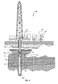
- FIG. 2 schematically shows a typical onshore hydrocarbon well location and surface equipments SE above hydrocarbon geological formations GF after wellbore WB drilling operations have been carried out, a casing string has been run and cementing operations have been carried out.
- the casing CA has been perforated PF in order to put in communication a selected portion of the formation containing hydrocarbon and the wellbore.
- a production tubing PT and a pumping arrangement PA have been inserted into the well bore WB.
- the pumping arrangement PA raises the hydrocarbon effluent HE to the surface.
- the hydrocarbon effluent HE enters the wellbore WB through the perforations PF below the pumping arrangement and flows in the production tubing PT towards surface treatment equipment ST.
- a production logging apparatus 1 to log while producing the hydrocarbon well according to the invention is coupled to the pumping arrangement PA and preferably disposed under the pumping arrangement PA.
- the surface equipments SE comprise an oil rig, surface treatment equipment ST and a surface unit SU.
- the surface unit may be a vehicle coupled to the production logging apparatus by a cable CB.
- the measurement data, which may be collected by the production logging apparatus 1, may be transmitted to the surface unit SU by any known technique, or otherwise stored in the production logging apparatus memory for subsequent processing when the memory is returned to the surface.
- the surface unit SU comprises appropriate electronic and software arrangements PR for processing, analyzing and storing the measurement data provided by the production logging apparatus 1.
- the delivery of electrical power from the surface, and communication between the downhole equipment and the surface unit may be accomplished using the electrical cables already in place to supply power to the pumping arrangement.
- Such communication is already in common use in oilfield applications for performing, and transmitting back to surface, measurements that may be used to characterize the pumping arrangement performance.
- the need for a separate surface unit SU is limited to the provision of a relatively simple computer and set of electronics for processing these telemetry signals, as no extra cable need be deployed.
- such an implementation will eliminate, or at least reduce, the need for much surface hardware (stuffing-box, pressure-control equipment, complex wellhead, etc...) that is usually required for production logging.
- FIGS. 3 and 4 are detailed views schematically showing the pumping arrangement PA and the production logging apparatus 1 of the invention according to a first and a second embodiment, respectively.
- the pumping arrangement PA is fitted into the wellbore WB and secured to the casing CA by, for example, a plug 9.
- the output of the pumping arrangement is coupled to a production tubing PT.
- the pumping arrangement PA is a standard electrical submersible pump. Advantageously, it is modified to allow power and telemetry connections to the production logging apparatus 1 attached below.
- the production logging apparatus 1 comprises a coupling module 2, an electronic module 3, a micro-winch 4, a docking station 5, a cable 7A, 7B, and a micro-production logging tool 6.
- the coupling module 2 couples the production logging apparatus 1 to the pumping arrangement PA. It provides a mechanical support for the production logging apparatus 1 below the pumping arrangement while allowing flow to enter the pumping arrangement.
- the coupling module 2 comprises flow entry ports and a flow output port. The flow entry ports may be disposed on the circumference of the coupling module 2. The flow output port corresponds to the flow entry port of the pumping arrangement. These features enable maximizing the flow penetrating into the pumping arrangement.
- the coupling module 2 also allows for electrical and possibly optical connections from the pumping arrangement to the electronic module 3 and the micro-winch 4.
- the production logging apparatus 1 is coupled to the pumping arrangement through the coupling module and the pumping arrangement PA and the production logging apparatus 1 are positioned in the wellbore WB at a desired depth.
- the electronic module 3 is a package of electronics comprising a winch controller 31, a powering module 32 to power the micro- production logging tool 6, and a telemetry module 33.
- the electronic module may also comprise usual powering means for the whole production logging apparatus 1.
- the winch controller 31 commands the operation of the micro-winch 4.
- the powering module 32 may comprise, for example, an inductive-coupling connection in order to power the micro- production logging tool 6 when locked in the docking station 5.
- the telemetry module 33 provides telemetry to and from the surface equipment, for example via the cable CB. Alternatively, other way of exchanging commands or data between the telemetry module and the surface equipment may be used, e.g. mud pulse technique.
- the cable CB also provides power to the electronic module 3 and the micro-winch 4.
- the micro-winch 4 may be a small motor-gear-drum arrangement. It enables to deploy the micro- production logging tool 6 at a desired depth below the pumping arrangement.
- the micro-winch 4 has automated spooling capability, and depth-measurement 41 and tension-measurement 42 devices.
- the depth-measurement device determines the depth position of the micro- production logging tool 6 relative to the surface level.
- the micro-winch is compact and has a limited capacity, as the length intervals to be logged below the pumping arrangement PA are usually small compared to the total well depth (i.e. relative to the surface).
- the micro-winch 4 is powered electrically, and controlled via the electronic module 3 from the surface.
- the docking station 5 provides a protective sleeve 52 around the micro- production logging tool 6 when the production logging apparatus 1 is run in the wellbore hole or pulled out of the wellbore, or when the micro- production logging tool 6 is inactive downhole.
- the docking station 5 comprises a latching mechanism to ensure positive engagement of the micro- production logging tool 6 at all times other than when an acquisition pass is underway. This enables preventing excessive stress on the cable or tool head.
- the docking station 5 may also comprise an inductive coupling link 51.
- This may enable transferring power to the micro-production logging tool 6, programming the next acquisition sequence, and retrieval of data stored within the micro- production logging tool 6 from a previous acquisition session when the micro- production logging tool is run in a memory mode that will be described in details hereinafter.
- the micro- production logging tool 6 comprises at least one sensor 63.
- the sensor may be of various types and may provide various measurement data related to the hydrocarbon geological formation and/or the hydrocarbon effluent contained within the geological formation or flowing into the wellbore.
- the sensor may be capable of pressure, temperature, flow, "holdup” (i.e. fraction of water, oil and gas present in the wellbore at a given depth), conductivity, resistivity, etc... measurements.
- Such measurements can be repeated for other azimuths and other depths.
- the winch and micro-production logging tool are at the same pressure downhole, there is no need for pressure-control equipment between them, and thus no need for any great weight to allow the tool to descend in the wellbore.
- the length of logging cable required to log the interval under investigation is typically very much shorter than the well depth, and thus the length and weight of the logging cable is greatly reduced as compared to typical production logging jobs run from surface.
- the total weight to be supported by the cable and the micro-winch is small compared to that when running a traditional production logging tool.
- the production logging tool enables running, in an automated fashion, production logs on a regular and routine basis when the tool is installed for a long period. For example, production logging runs may be made every day in order to monitor the evolution of the well characteristics. This potentially opens new markets for well evaluation.
- FIG. 3 schematically depicts the production logging apparatus 1 of the invention according to a first embodiment.
- the micro- production logging tool 6 works in a memory mode, namely the acquired data is stored within the micro- production logging tool.
- the micro- production logging tool 6 according to the first embodiment comprises a battery 61, a memory 62, at least one sensor 63 and is coupled to the micro-winch 5 through a slickline 7A.
- the slickline 7A is a non electric cable usually containing no component permitting real-time telemetry to or from the micro- production logging tool 6.
- the micro- production logging tool works according to the memory mode, measurement data is acquired and stored within the memory 62.
- the inductive coupling link 51 enables charging of the battery 61, programming of the next desired acquisition sequence, and retrieval of the data stored in the memory 62.
- FIG.4 schematically depicts the production logging apparatus 1 of the invention according to a second embodiment.
- the micro-production logging tool 6 works in "real-time mode", namely the measurement data is transmitted in real time to the electronic module 3.
- the micro- production logging tool 6 according to the second embodiment comprises only at least one sensor 63 and is coupled to the micro-winch 5 through a wireline 7B.
- the wireline 7B is usually an electrical or optical cable enabling power and/or telemetry connection between the micro- production logging tool 6 and the electronic module 3 via the micro-winch 5.
- the wireline 7B offers the ability to send significant power to the micro- production logging tool 6, as well as control its operation and retrieve its measurement data in real time. Further, the battery and/or the memory become unnecessary.
- the production logging tool 1 may further comprise a tractoring device permitting entry into highly-deviated portions of the wellbore below the pumping arrangement.
Landscapes
- Geology (AREA)
- Life Sciences & Earth Sciences (AREA)
- Engineering & Computer Science (AREA)
- Mining & Mineral Resources (AREA)
- Physics & Mathematics (AREA)
- Environmental & Geological Engineering (AREA)
- Fluid Mechanics (AREA)
- General Life Sciences & Earth Sciences (AREA)
- Geochemistry & Mineralogy (AREA)
- Geophysics (AREA)
- Geophysics And Detection Of Objects (AREA)
- Arrangements For Transmission Of Measured Signals (AREA)
- Structures Of Non-Positive Displacement Pumps (AREA)
- General Factory Administration (AREA)
Abstract
- a coupling module 2 providing a mechanical support for the production logging apparatus 1 below a pumping arrangement PA disposed in a wellbore WB, and allowing flow to enter the pumping arrangement PA,
- an electronic module 3 comprising a winch controller 31, a powering module 32 and a telemetry module 33,
- a micro-winch 4,
- a docking station 5 comprising a latching mechanism for ensuring positive engagement of a micro- production logging tool 6, and
- a micro- production logging tool 6 comprising at least one sensor 63 and coupled to the micro-winch 4 by a cable 7.
Description
- The invention relates to an apparatus and a method of production logging. The invention finds a particular application in the oilfield industry.
- "Production Logging" is a common, long-established technique for determining the contribution of various producing depth intervals in a hydrocarbon well to the total flow and fluid composition that is observed at surface. Many different sensor types and tool configurations exist to make the measurements that such techniques require.
In a naturally-producing well, where the reservoir pressure is sufficient to cause fluids to flow from the formation into the wellbore, it is relatively simple to lower a logging tool comprising such production logging sensors on wireline or on slickline.
In a well where the reservoir pressure is not sufficient to cause fluids to flow from the formation GF into the wellbore WB, a pumping arrangement PA (often abbreviated as ESP: Electrical Submersible Pump) is required to raise fluids to the surface ST as schematically depicted inFIG. 1 . Fluid enters the wellbore below the pumping arrangement. Above the pump, the fluid flows usually in production tubing PT that channels the pumping arrangement output to surface. Clearly, in either case it is necessary to perform the production logging data acquisition below the pumping arrangement, as this is where the fluid is entering the wellbore. However, such a pumping arrangement PA represents a mechanical obstacle to lower a logging tool TL into the wellbore WB.
A first known technique enabling logging below the pumping arrangement is to install a branch in the tubing known as a "Y-tool" YT. The pumping arrangement PA is comprised in one of the branches of the Y-tool YT. By removing a plug in the other branch of the Y-tool YT, the logging tool can be lowered below the pumping arrangement PA. However, this technique requires removing the plug before logging, and replacing it afterwards. Further, with this technique it is necessary to seal around the cable LN while running the production logging acquisition. Furthermore, the pumping arrangement needs to be mechanically bypassed, which restricts the size of both the pumping arrangement and the logging tool. - A second known technique enabling logging below the pumping arrangement is described in document
US 6,120,261 . This document describes a combined electric motor and submersible pump apparatus intended for installation in line with the well tubing. The apparatus comprises a hollow drive shaft having a downstream end secured to the rotor of the motor and mounted for rotation in axial alignment with the axis of the tubing. The pump impellers are mounted on the upstream end of the hollow shaft. The shaft also has inlet and discharge ports and a check valve mounted on the interior of the drive shaft that is closed when the pump is activated. When the check valve is in the open position, a wire line tool can be passed through the hollow drive shaft to a position below the apparatus. However, this technique requires considerably modifying the structure of the pumping arrangement. Further, it is more expensive than standard pumping arrangements. - It is an object of the invention to propose an apparatus and a method to log while producing a hydrocarbon well that overcomes at least one of the drawbacks of the prior art apparatuses and methods.
- According to an aspect, the invention relates to a production logging apparatus comprising:
- a coupling module providing a mechanical support for the production logging apparatus below a pumping arrangement disposed in a wellbore, and allowing flow to enter the pumping arrangement,
- an electronic module comprising a winch controller, a powering module and a telemetry module,
- a micro-winch,
- a docking station comprising a latching mechanism for ensuring positive engagement of a micro- production logging tool, and
- a micro- production logging tool comprising at least one sensor and coupled to the micro-winch by a cable.
- The micro-winch may be a motor-gear-drum arrangement.
The micro-winch may have automated spooling capability, and comprises depth-measurement and tension-measurement devices. - The docking station may also comprise an inductive coupling link to transfer power and command to the micro- production logging tool, and retrieve measurement data from the micro- production logging tool when the micro- production logging tool is latched in the docking station.
The micro- production logging tool may further comprise a battery and a memory, and may be further coupled to the micro-winch through a slickline.
Alternatively, the micro- production logging tool may be coupled to the micro-winch through an electrically-conductive wireline. Advantageously, the wireline permits delivery of electrical power to the tool from the docking station and real-time communication between the tool and the docking station.
Advantageously, the production logging apparatus may be coupled to a surface unit through a cable coupling the pumping arrangement to a surface equipment. - According to a further aspect, the invention relates to a production logging method comprising the steps of:
- coupling a production logging apparatus comprising a coupling module, an electronic module, a micro-winch, a docking station and a micro- production logging tool according to the invention below a pumping arrangement, the micro- production logging tool being latched into the docking station,
- positioning the pumping arrangement together with the production logging apparatus in a wellbore, and
- commanding the micro-winch in order to deploy the micro- production logging tool in the wellbore below the pumping arrangement, and log a depth interval.
- The production logging method may further comprise transmitting in real-time measurement data from the micro- production logging tool to the electronic module.
Alternatively, the production logging method may further comprise: - storing measurement data in the micro- production logging tool and transmitting said data to the electronic module,
- returning the micro- production logging tool in the docking station, and
- retrieving said data from the micro- production logging tool into the electronic module.
- The production logging method may further comprise driving and powering the production logging apparatus through a cable coupling the pumping arrangement to a surface equipment.
- Thus, the invention enables logging below a pumping arrangement in a producing well while not using any special Y-tool. The invention has numerous advantages, including the ability to perform multiple production logging acquisitions at regular time intervals without the need for repeated wireline runs, in cases where the apparatus of the invention is installed downhole for a long period of time.
The simplified micro winch design and the production logging tool miniaturization enable running any production logging sensors below the pumping arrangement regardless of the wellbore diameter.
The production logging apparatus of the invention can be designed in near real-time configuration or in real time configuration. In the near real-time configuration, the measurement data can be retrieved from the tool memory as soon as the log is completed and the micro production logging tool is returned in its docking station. In the real-time configuration, the measurement data can be transmitted to the surface during the logging operation. Both configurations enable interpretation of the logging data without the need to return the logging tool back to surface, and thus without any time loss.
These and other aspects of the invention will be apparent from and elucidated with reference to the embodiments described hereinafter. - The present invention is illustrated by way of example and not limited to the accompanying figures, in which like references indicate similar elements:
-
FIG. 1 schematically shows a typical onshore hydrocarbon well location and a pumping arrangement and logging tool according to the prior art; -
FIG.2 schematically shows a typical onshore hydrocarbon well location and a pumping arrangement and production logging apparatus according to the invention; -
FIGS. 3 and4 are detailed views schematically showing the pumping arrangement and the production logging apparatus of the invention according to a first and a second embodiment, respectively. -
FIG. 2 schematically shows a typical onshore hydrocarbon well location and surface equipments SE above hydrocarbon geological formations GF after wellbore WB drilling operations have been carried out, a casing string has been run and cementing operations have been carried out. The casing CA has been perforated PF in order to put in communication a selected portion of the formation containing hydrocarbon and the wellbore. Further, a production tubing PT and a pumping arrangement PA have been inserted into the well bore WB. The pumping arrangement PA raises the hydrocarbon effluent HE to the surface. The hydrocarbon effluent HE enters the wellbore WB through the perforations PF below the pumping arrangement and flows in the production tubing PT towards surface treatment equipment ST. Though not shown in the drawings, when no production tubing is present, the fluid may flow simply in the casing in which the pumping arrangement is installed.
Aproduction logging apparatus 1 to log while producing the hydrocarbon well according to the invention is coupled to the pumping arrangement PA and preferably disposed under the pumping arrangement PA.
In this example, the surface equipments SE comprise an oil rig, surface treatment equipment ST and a surface unit SU. The surface unit may be a vehicle coupled to the production logging apparatus by a cable CB. The measurement data, which may be collected by theproduction logging apparatus 1, may be transmitted to the surface unit SU by any known technique, or otherwise stored in the production logging apparatus memory for subsequent processing when the memory is returned to the surface. The surface unit SU comprises appropriate electronic and software arrangements PR for processing, analyzing and storing the measurement data provided by theproduction logging apparatus 1.
The delivery of electrical power from the surface, and communication between the downhole equipment and the surface unit, may be accomplished using the electrical cables already in place to supply power to the pumping arrangement. Such communication is already in common use in oilfield applications for performing, and transmitting back to surface, measurements that may be used to characterize the pumping arrangement performance. In such an implementation, the need for a separate surface unit SU is limited to the provision of a relatively simple computer and set of electronics for processing these telemetry signals, as no extra cable need be deployed. In addition, such an implementation will eliminate, or at least reduce, the need for much surface hardware (stuffing-box, pressure-control equipment, complex wellhead, etc...) that is usually required for production logging. -
FIGS. 3 and4 are detailed views schematically showing the pumping arrangement PA and theproduction logging apparatus 1 of the invention according to a first and a second embodiment, respectively.
The pumping arrangement PA is fitted into the wellbore WB and secured to the casing CA by, for example, aplug 9. The output of the pumping arrangement is coupled to a production tubing PT. The pumping arrangement PA is a standard electrical submersible pump. Advantageously, it is modified to allow power and telemetry connections to theproduction logging apparatus 1 attached below. - The
production logging apparatus 1 comprises acoupling module 2, anelectronic module 3, amicro-winch 4, adocking station 5, acable micro-production logging tool 6. - The
coupling module 2 couples theproduction logging apparatus 1 to the pumping arrangement PA. It provides a mechanical support for theproduction logging apparatus 1 below the pumping arrangement while allowing flow to enter the pumping arrangement. Thecoupling module 2 comprises flow entry ports and a flow output port. The flow entry ports may be disposed on the circumference of thecoupling module 2. The flow output port corresponds to the flow entry port of the pumping arrangement. These features enable maximizing the flow penetrating into the pumping arrangement. Thecoupling module 2 also allows for electrical and possibly optical connections from the pumping arrangement to theelectronic module 3 and themicro-winch 4. Typically, theproduction logging apparatus 1 is coupled to the pumping arrangement through the coupling module and the pumping arrangement PA and theproduction logging apparatus 1 are positioned in the wellbore WB at a desired depth. - The
electronic module 3 is a package of electronics comprising awinch controller 31, a poweringmodule 32 to power the micro-production logging tool 6, and atelemetry module 33. The electronic module may also comprise usual powering means for the wholeproduction logging apparatus 1. Thewinch controller 31 commands the operation of themicro-winch 4. The poweringmodule 32 may comprise, for example, an inductive-coupling connection in order to power the micro-production logging tool 6 when locked in thedocking station 5. Thetelemetry module 33 provides telemetry to and from the surface equipment, for example via the cable CB. Alternatively, other way of exchanging commands or data between the telemetry module and the surface equipment may be used, e.g. mud pulse technique. Advantageously, the cable CB also provides power to theelectronic module 3 and themicro-winch 4. - The micro-winch 4 may be a small motor-gear-drum arrangement. It enables to deploy the micro-
production logging tool 6 at a desired depth below the pumping arrangement. Advantageously, themicro-winch 4 has automated spooling capability, and depth-measurement 41 and tension-measurement 42 devices. The depth-measurement device determines the depth position of the micro-production logging tool 6 relative to the surface level. Advantageously, the micro-winch is compact and has a limited capacity, as the length intervals to be logged below the pumping arrangement PA are usually small compared to the total well depth (i.e. relative to the surface). The micro-winch 4 is powered electrically, and controlled via theelectronic module 3 from the surface. - The
docking station 5 provides aprotective sleeve 52 around the micro-production logging tool 6 when theproduction logging apparatus 1 is run in the wellbore hole or pulled out of the wellbore, or when the micro-production logging tool 6 is inactive downhole. Advantageously, thedocking station 5 comprises a latching mechanism to ensure positive engagement of the micro-production logging tool 6 at all times other than when an acquisition pass is underway. This enables preventing excessive stress on the cable or tool head. Thedocking station 5 may also comprise aninductive coupling link 51. This may enable transferring power to themicro-production logging tool 6, programming the next acquisition sequence, and retrieval of data stored within the micro-production logging tool 6 from a previous acquisition session when the micro- production logging tool is run in a memory mode that will be described in details hereinafter. - The micro-
production logging tool 6 comprises at least onesensor 63. The sensor may be of various types and may provide various measurement data related to the hydrocarbon geological formation and/or the hydrocarbon effluent contained within the geological formation or flowing into the wellbore. For example, the sensor may be capable of pressure, temperature, flow, "holdup" (i.e. fraction of water, oil and gas present in the wellbore at a given depth), conductivity, resistivity, etc... measurements. Once themicro-production logging tool 6 is positioned at a desired depth due to the operation of the micro-winch under the command of thewinch controller 31, characteristic parameters of a selected zone of the formation, or of the fluid in the vicinity of the micro-production logging tool 6 can be measured. Such measurements can be repeated for other azimuths and other depths. As the winch and micro-production logging tool are at the same pressure downhole, there is no need for pressure-control equipment between them, and thus no need for any great weight to allow the tool to descend in the wellbore. Further, the length of logging cable required to log the interval under investigation is typically very much shorter than the well depth, and thus the length and weight of the logging cable is greatly reduced as compared to typical production logging jobs run from surface. As a consequence, the total weight to be supported by the cable and the micro-winch is small compared to that when running a traditional production logging tool. The production logging tool enables running, in an automated fashion, production logs on a regular and routine basis when the tool is installed for a long period. For example, production logging runs may be made every day in order to monitor the evolution of the well characteristics. This potentially opens new markets for well evaluation. -
FIG. 3 schematically depicts theproduction logging apparatus 1 of the invention according to a first embodiment. In the first embodiment, the micro-production logging tool 6 works in a memory mode, namely the acquired data is stored within the micro- production logging tool. The micro-production logging tool 6 according to the first embodiment comprises a battery 61, a memory 62, at least onesensor 63 and is coupled to the micro-winch 5 through aslickline 7A. Theslickline 7A is a non electric cable usually containing no component permitting real-time telemetry to or from the micro-production logging tool 6. When, the micro- production logging tool works according to the memory mode, measurement data is acquired and stored within the memory 62. When the micro-production logging tool 6 is housed in thedocking station 5, for example after the acquisition pass is completed, theinductive coupling link 51 enables charging of the battery 61, programming of the next desired acquisition sequence, and retrieval of the data stored in the memory 62. -
FIG.4 schematically depicts theproduction logging apparatus 1 of the invention according to a second embodiment. In the second embodiment, themicro-production logging tool 6 works in "real-time mode", namely the measurement data is transmitted in real time to theelectronic module 3. The micro-production logging tool 6 according to the second embodiment comprises only at least onesensor 63 and is coupled to the micro-winch 5 through awireline 7B. Thewireline 7B is usually an electrical or optical cable enabling power and/or telemetry connection between the micro-production logging tool 6 and theelectronic module 3 via themicro-winch 5. Thewireline 7B offers the ability to send significant power to the micro-production logging tool 6, as well as control its operation and retrieve its measurement data in real time. Further, the battery and/or the memory become unnecessary. - As an alternative embodiment not shown, the
production logging tool 1 may further comprise a tractoring device permitting entry into highly-deviated portions of the wellbore below the pumping arrangement. - Though the invention has been described in relation with a particular application of the analyzing device to an onshore hydrocarbon well location, the invention may also apply to offshore hydrocarbon well locations. Further, the invention is not limited to oilfield application, as those versed in the art will recognize that the invention may apply in other applications where measurements need to be performed under downhole pumping arrangement, for example in a water well.
The drawings and their description hereinbefore illustrate rather than limit the invention.
Any reference sign in a claim should not be construed as limiting the claim. The word "comprising" does not exclude the presence of other elements than those listed in a claim. The word "a" or "an" preceding an element does not exclude the presence of a plurality of such element.
Claims (11)
- A production logging apparatus (1) comprises:- a coupling module (2) providing a mechanical support for the production logging apparatus (1) below a pumping arrangement (PA) disposed in a wellbore (WB), and allowing flow to enter the pumping arrangement (PA),- an electronic module (3) comprising a winch controller (31), a powering module (32) and a telemetry module (33),- a micro-winch (4),- a docking station (5) comprising a latching mechanism for ensuring positive engagement of a micro- production logging tool (6), and- a micro- production logging tool (6) comprising at least one sensor (63) and coupled to the micro-winch (4) by a cable (7).
- The production logging apparatus (1) according to claim 1, wherein the micro-winch (4) is a motor-gear-drum arrangement.
- The production logging apparatus (1) according to claim 2, wherein the micro-winch (4) has automated spooling capability, and comprises depth-measurement (41) and tension-measurement (42) devices.
- The production logging apparatus (1) according to any one of the preceding claims, wherein the docking station (5) also comprises an inductive coupling link (51) to transfer power and commands to the micro- production logging tool (6), and retrieve measurement data from the micro- production logging tool (6) when the micro- production logging tool (6) is latched in the docking station (5).
- The production logging apparatus (1) according to any one of the preceding claims, wherein the micro- production logging tool (6) further comprises a battery (61) and a memory (62), and is coupled to the micro-winch (5) through a slickline (7A).
- The production logging apparatus (1) according to any one of the preceding claims, wherein the micro- production logging tool (6) is coupled to the micro-winch (5) through a wireline (7B).
- The production logging apparatus (1) according to any one of the preceding claims, wherein the production logging apparatus (1) is coupled to a surface unit (SU) through a cable (CB) coupling the pumping arrangement (PA) to a surface equipment (SE).
- A production logging method comprises the steps of:- coupling a production logging apparatus (1) comprising a coupling module (2), an electronic module (3), a micro-winch (4), a docking station (5) and a micro-production logging tool (6) according to anyone of the claims 1 to 7 below a pumping arrangement (PA), the micro- production logging tool (6) being latched into the docking station (5),- positioning the pumping arrangement (PA) together with the production logging apparatus (1) in a wellbore (WB), and- commanding the micro-winch (4) in order to deploy the micro- production logging tool (6) in the wellbore (WB) below the pumping arrangement (PA), and log a depth interval.
- The production logging method according to claim 8, wherein it further comprises transmitting in real-time measurement data from the micro- production logging tool (6) to the electronic module (3).
- The production logging method according to claim 8, wherein it further comprises:- storing measurement data in the micro- production logging tool (6) and transmitting said data to the electronic module (3),- returning the micro- production logging tool (6) in the docking station (5), and- retrieving said data from the micro- production logging tool (6) into the electronic module (3).
- The production logging method according to claim 8, wherein it further comprises driving and powering the production logging apparatus (1) through a cable (CB) coupling the pumping arrangement (PA) to a surface equipment (SE).
Priority Applications (5)
| Application Number | Priority Date | Filing Date | Title |
|---|---|---|---|
| AT07117577T ATE513117T1 (en) | 2007-09-28 | 2007-09-28 | DEVICE AND METHOD FOR RECORDING DURING PRODUCTION |
| EP07117577A EP2042683B1 (en) | 2007-09-28 | 2007-09-28 | A logging while producing apparatus and method |
| CA2639465A CA2639465C (en) | 2007-09-28 | 2008-09-10 | A logging while producing apparatus and method |
| US12/236,649 US8087461B2 (en) | 2007-09-28 | 2008-09-24 | Logging while producing apparatus and method |
| CN200810161917.4A CN101397901B (en) | 2007-09-28 | 2008-09-27 | Apparatus and method for production logging |
Applications Claiming Priority (1)
| Application Number | Priority Date | Filing Date | Title |
|---|---|---|---|
| EP07117577A EP2042683B1 (en) | 2007-09-28 | 2007-09-28 | A logging while producing apparatus and method |
Publications (2)
| Publication Number | Publication Date |
|---|---|
| EP2042683A1 true EP2042683A1 (en) | 2009-04-01 |
| EP2042683B1 EP2042683B1 (en) | 2011-06-15 |
Family
ID=38776163
Family Applications (1)
| Application Number | Title | Priority Date | Filing Date |
|---|---|---|---|
| EP07117577A Not-in-force EP2042683B1 (en) | 2007-09-28 | 2007-09-28 | A logging while producing apparatus and method |
Country Status (5)
| Country | Link |
|---|---|
| US (1) | US8087461B2 (en) |
| EP (1) | EP2042683B1 (en) |
| CN (1) | CN101397901B (en) |
| AT (1) | ATE513117T1 (en) |
| CA (1) | CA2639465C (en) |
Cited By (3)
| Publication number | Priority date | Publication date | Assignee | Title |
|---|---|---|---|---|
| RU2538013C1 (en) * | 2013-12-24 | 2015-01-10 | Открытое акционерное общество "Ижевский радиозавод" | Telemetry system of operated well |
| WO2015009923A3 (en) * | 2013-07-19 | 2015-06-25 | Ge Oil & Gas Esp, Inc. | Forward deployed sensing array for an electric submersible pump |
| RU180608U1 (en) * | 2018-03-12 | 2018-06-19 | Акционерное общество "Ижевский радиозавод" | SUBMERSIBLE UNIT |
Families Citing this family (18)
| Publication number | Priority date | Publication date | Assignee | Title |
|---|---|---|---|---|
| ATE513117T1 (en) * | 2007-09-28 | 2011-07-15 | Prad Res & Dev Nv | DEVICE AND METHOD FOR RECORDING DURING PRODUCTION |
| US9482233B2 (en) * | 2008-05-07 | 2016-11-01 | Schlumberger Technology Corporation | Electric submersible pumping sensor device and method |
| US8390295B2 (en) * | 2008-07-11 | 2013-03-05 | Baker Hughes Incorporated | Method and apparatus for focusing in resistivity measurement tools using independent electrical sources |
| US20120215449A1 (en) * | 2009-10-30 | 2012-08-23 | Hallundbaek Joergen | Logging tool |
| US20120235829A1 (en) * | 2011-03-17 | 2012-09-20 | Sarmad Adnan | Systems and methods of oilfield equipment via inductive coupling |
| US9556707B2 (en) | 2012-07-10 | 2017-01-31 | Halliburton Energy Services, Inc. | Eletric subsurface safety valve with integrated communications system |
| US9719315B2 (en) | 2013-11-15 | 2017-08-01 | Ge Oil & Gas Esp, Inc. | Remote controlled self propelled deployment system for horizontal wells |
| US9598943B2 (en) | 2013-11-15 | 2017-03-21 | Ge Oil & Gas Esp, Inc. | Distributed lift systems for oil and gas extraction |
| US10625977B2 (en) | 2015-10-20 | 2020-04-21 | Schlumberger Technology Corporation | Method and system for detecting faults and abnormal wear conditions in oil and gas wireline logging winch units |
| US11021939B2 (en) | 2015-12-11 | 2021-06-01 | Schlumberger Technology Corporation | System and method related to pumping fluid in a borehole |
| GB2552320B (en) * | 2016-07-18 | 2020-10-21 | Weatherford Uk Ltd | Apparatus and method for downhole data acquisition and/or monitoring |
| US11002093B2 (en) * | 2019-02-04 | 2021-05-11 | Saudi Arabian Oil Company | Semi-autonomous downhole taxi with fiber optic communication |
| EP3744981B1 (en) * | 2019-05-28 | 2024-08-07 | Grundfos Holding A/S | Submersible pump assembly and method for operating the submersible pump assembly |
| US11661809B2 (en) * | 2020-06-08 | 2023-05-30 | Saudi Arabian Oil Company | Logging a well |
| US11732537B2 (en) * | 2021-09-29 | 2023-08-22 | Halliburton Energy Services, Inc. | Anchor point device for formation testing relative measurements |
| CN114658418B (en) * | 2022-04-29 | 2024-04-26 | 西安石竹能源科技有限公司 | Electric position limiting instrument for locking underground optical cable azimuth |
| US12196050B2 (en) | 2022-08-18 | 2025-01-14 | Saudi Arabian Oil Company | Logging a deviated or horizontal well |
| GB2640155A (en) * | 2024-04-03 | 2025-10-15 | Schlumberger Technology Bv | Hanging production logging tools below a cable deployed electric submersible pump |
Citations (3)
| Publication number | Priority date | Publication date | Assignee | Title |
|---|---|---|---|---|
| US4450539A (en) * | 1981-07-29 | 1984-05-22 | Standard Oil Company (Indiana) | Apparatus for measuring the relative position of a downhole tool in a bore hole |
| EP0417369A1 (en) * | 1989-09-14 | 1991-03-20 | Societe De Prospection Electrique Schlumberger | Method and apparatus for logging a well below a downhole pump |
| US20050263289A1 (en) * | 2004-05-27 | 2005-12-01 | Kanady Edward C | Method and apparatus for aligning rotor in stator of a rod driven well pump |
Family Cites Families (15)
| Publication number | Priority date | Publication date | Assignee | Title |
|---|---|---|---|---|
| US3917230A (en) * | 1972-01-24 | 1975-11-04 | Byron Jackson Inc | Well drilling control system |
| US4098342A (en) * | 1977-05-25 | 1978-07-04 | Exxon Production Research Company | Method and apparatus for maintaining electric cable inside drill pipe |
| US4157657A (en) * | 1977-10-13 | 1979-06-12 | General Dynamics Electronics Division | Profiling water quality sensing system |
| US4358088A (en) * | 1980-10-14 | 1982-11-09 | Paccar Of Canada Ltd. | Winch drive and braking mechanism |
| GB8401315D0 (en) * | 1984-01-18 | 1984-02-22 | Graser J A | Wireline apparatus |
| CN2371339Y (en) * | 1998-12-13 | 2000-03-29 | 山东滨州市胜滨石油机械厂 | Logging winch collector ring |
| CA2269300A1 (en) * | 1999-04-16 | 2000-10-16 | Rene Grande | Strainer nipple tool |
| US6904797B2 (en) * | 2001-12-19 | 2005-06-14 | Schlumberger Technology Corporation | Production profile determination and modification system |
| US7063306B2 (en) * | 2003-10-01 | 2006-06-20 | Paccar Inc | Electronic winch monitoring system |
| US7495446B2 (en) * | 2005-08-23 | 2009-02-24 | Schlumberger Technology Corporation | Formation evaluation system and method |
| US8022838B2 (en) * | 2005-10-28 | 2011-09-20 | Thrubit B.V. | Logging system, method of logging an earth formation and method of producing a hydrocarbon fluid |
| US7640979B2 (en) * | 2006-06-23 | 2010-01-05 | Schlumberger Technology Corporation | System for well logging |
| GB0701061D0 (en) * | 2007-01-19 | 2007-02-28 | Head Phillip | Wireline or coiled tubing deployed electric submersible pump |
| ATE513117T1 (en) * | 2007-09-28 | 2011-07-15 | Prad Res & Dev Nv | DEVICE AND METHOD FOR RECORDING DURING PRODUCTION |
| US8201625B2 (en) * | 2007-12-26 | 2012-06-19 | Schlumberger Technology Corporation | Borehole imaging and orientation of downhole tools |
-
2007
- 2007-09-28 AT AT07117577T patent/ATE513117T1/en not_active IP Right Cessation
- 2007-09-28 EP EP07117577A patent/EP2042683B1/en not_active Not-in-force
-
2008
- 2008-09-10 CA CA2639465A patent/CA2639465C/en not_active Expired - Fee Related
- 2008-09-24 US US12/236,649 patent/US8087461B2/en not_active Expired - Fee Related
- 2008-09-27 CN CN200810161917.4A patent/CN101397901B/en not_active Expired - Fee Related
Patent Citations (3)
| Publication number | Priority date | Publication date | Assignee | Title |
|---|---|---|---|---|
| US4450539A (en) * | 1981-07-29 | 1984-05-22 | Standard Oil Company (Indiana) | Apparatus for measuring the relative position of a downhole tool in a bore hole |
| EP0417369A1 (en) * | 1989-09-14 | 1991-03-20 | Societe De Prospection Electrique Schlumberger | Method and apparatus for logging a well below a downhole pump |
| US20050263289A1 (en) * | 2004-05-27 | 2005-12-01 | Kanady Edward C | Method and apparatus for aligning rotor in stator of a rod driven well pump |
Cited By (4)
| Publication number | Priority date | Publication date | Assignee | Title |
|---|---|---|---|---|
| WO2015009923A3 (en) * | 2013-07-19 | 2015-06-25 | Ge Oil & Gas Esp, Inc. | Forward deployed sensing array for an electric submersible pump |
| US9494029B2 (en) | 2013-07-19 | 2016-11-15 | Ge Oil & Gas Esp, Inc. | Forward deployed sensing array for an electric submersible pump |
| RU2538013C1 (en) * | 2013-12-24 | 2015-01-10 | Открытое акционерное общество "Ижевский радиозавод" | Telemetry system of operated well |
| RU180608U1 (en) * | 2018-03-12 | 2018-06-19 | Акционерное общество "Ижевский радиозавод" | SUBMERSIBLE UNIT |
Also Published As
| Publication number | Publication date |
|---|---|
| CA2639465A1 (en) | 2009-03-28 |
| US8087461B2 (en) | 2012-01-03 |
| US20090084543A1 (en) | 2009-04-02 |
| EP2042683B1 (en) | 2011-06-15 |
| CN101397901A (en) | 2009-04-01 |
| ATE513117T1 (en) | 2011-07-15 |
| CA2639465C (en) | 2016-05-03 |
| CN101397901B (en) | 2014-03-05 |
Similar Documents
| Publication | Publication Date | Title |
|---|---|---|
| US8087461B2 (en) | Logging while producing apparatus and method | |
| US9109439B2 (en) | Wellbore telemetry system and method | |
| CN101285374B (en) | Method and apparatus for pipeline transport logging | |
| CA1071530A (en) | Method and apparatus for running and retrieving logging instruments in highly deviated well bores | |
| US8561698B2 (en) | Downhole fluid injection | |
| US9447664B2 (en) | Multi-zone formation evaluation systems and methods | |
| US6745844B2 (en) | Hydraulic power source for downhole instruments and actuators | |
| EP2785960B1 (en) | Modular downhole tools and methods | |
| CA2537502C (en) | Separable plug for use in a wellbore | |
| EP2241717A2 (en) | System and method for communicating between a drill string and a logging instrument | |
| US20120061090A1 (en) | Landing string assembly | |
| US11661809B2 (en) | Logging a well | |
| US11512546B2 (en) | Coiled tubing electronically controlled multilateral access of extended reach wells | |
| CA2593416C (en) | Hybrid wellbore telemetry system and method | |
| MX2007008966A (en) | Wellbore telemetry system and method. | |
| US20100064794A1 (en) | Method and apparatus for formation evaluation after drilling | |
| US12196050B2 (en) | Logging a deviated or horizontal well | |
| US20070044959A1 (en) | Apparatus and method for evaluating a formation | |
| CN109072678B (en) | Methods for packaging components, assemblies and modules in downhole tools | |
| US10914167B2 (en) | System for deploying communication components in a borehole | |
| US20090084542A1 (en) | Wellbore power and/or data transmission devices and methods | |
| CN116096980A (en) | Dual telemetry system with coiled tubing enabled |
Legal Events
| Date | Code | Title | Description |
|---|---|---|---|
| PUAI | Public reference made under article 153(3) epc to a published international application that has entered the european phase |
Free format text: ORIGINAL CODE: 0009012 |
|
| AK | Designated contracting states |
Kind code of ref document: A1 Designated state(s): AT BE BG CH CY CZ DE DK EE ES FI FR GB GR HU IE IS IT LI LT LU LV MC MT NL PL PT RO SE SI SK TR |
|
| AX | Request for extension of the european patent |
Extension state: AL BA HR MK RS |
|
| AKX | Designation fees paid | ||
| 17P | Request for examination filed |
Effective date: 20091112 |
|
| RBV | Designated contracting states (corrected) |
Designated state(s): AT BE BG CH CY CZ DE DK EE ES FI FR GB GR HU IE IS IT LI LT LU LV MC MT NL PL PT RO SE SI SK TR |
|
| REG | Reference to a national code |
Ref country code: DE Ref legal event code: 8566 |
|
| GRAP | Despatch of communication of intention to grant a patent |
Free format text: ORIGINAL CODE: EPIDOSNIGR1 |
|
| GRAS | Grant fee paid |
Free format text: ORIGINAL CODE: EPIDOSNIGR3 |
|
| GRAA | (expected) grant |
Free format text: ORIGINAL CODE: 0009210 |
|
| AK | Designated contracting states |
Kind code of ref document: B1 Designated state(s): AT BE BG CH CY CZ DE DK EE ES FI FR GB GR HU IE IS IT LI LT LU LV MC MT NL PL PT RO SE SI SK TR |
|
| REG | Reference to a national code |
Ref country code: GB Ref legal event code: FG4D Ref country code: CH Ref legal event code: EP |
|
| REG | Reference to a national code |
Ref country code: IE Ref legal event code: FG4D |
|
| REG | Reference to a national code |
Ref country code: DE Ref legal event code: R096 Ref document number: 602007015187 Country of ref document: DE Effective date: 20110721 |
|
| REG | Reference to a national code |
Ref country code: NL Ref legal event code: VDEP Effective date: 20110615 |
|
| PG25 | Lapsed in a contracting state [announced via postgrant information from national office to epo] |
Ref country code: LT Free format text: LAPSE BECAUSE OF FAILURE TO SUBMIT A TRANSLATION OF THE DESCRIPTION OR TO PAY THE FEE WITHIN THE PRESCRIBED TIME-LIMIT Effective date: 20110615 Ref country code: SE Free format text: LAPSE BECAUSE OF FAILURE TO SUBMIT A TRANSLATION OF THE DESCRIPTION OR TO PAY THE FEE WITHIN THE PRESCRIBED TIME-LIMIT Effective date: 20110615 |
|
| PG25 | Lapsed in a contracting state [announced via postgrant information from national office to epo] |
Ref country code: SI Free format text: LAPSE BECAUSE OF FAILURE TO SUBMIT A TRANSLATION OF THE DESCRIPTION OR TO PAY THE FEE WITHIN THE PRESCRIBED TIME-LIMIT Effective date: 20110615 Ref country code: CY Free format text: LAPSE BECAUSE OF FAILURE TO SUBMIT A TRANSLATION OF THE DESCRIPTION OR TO PAY THE FEE WITHIN THE PRESCRIBED TIME-LIMIT Effective date: 20110615 Ref country code: GR Free format text: LAPSE BECAUSE OF FAILURE TO SUBMIT A TRANSLATION OF THE DESCRIPTION OR TO PAY THE FEE WITHIN THE PRESCRIBED TIME-LIMIT Effective date: 20110916 Ref country code: LV Free format text: LAPSE BECAUSE OF FAILURE TO SUBMIT A TRANSLATION OF THE DESCRIPTION OR TO PAY THE FEE WITHIN THE PRESCRIBED TIME-LIMIT Effective date: 20110615 Ref country code: AT Free format text: LAPSE BECAUSE OF FAILURE TO SUBMIT A TRANSLATION OF THE DESCRIPTION OR TO PAY THE FEE WITHIN THE PRESCRIBED TIME-LIMIT Effective date: 20110615 Ref country code: FI Free format text: LAPSE BECAUSE OF FAILURE TO SUBMIT A TRANSLATION OF THE DESCRIPTION OR TO PAY THE FEE WITHIN THE PRESCRIBED TIME-LIMIT Effective date: 20110615 |
|
| PG25 | Lapsed in a contracting state [announced via postgrant information from national office to epo] |
Ref country code: BE Free format text: LAPSE BECAUSE OF FAILURE TO SUBMIT A TRANSLATION OF THE DESCRIPTION OR TO PAY THE FEE WITHIN THE PRESCRIBED TIME-LIMIT Effective date: 20110615 Ref country code: NL Free format text: LAPSE BECAUSE OF FAILURE TO SUBMIT A TRANSLATION OF THE DESCRIPTION OR TO PAY THE FEE WITHIN THE PRESCRIBED TIME-LIMIT Effective date: 20110615 |
|
| PG25 | Lapsed in a contracting state [announced via postgrant information from national office to epo] |
Ref country code: PT Free format text: LAPSE BECAUSE OF FAILURE TO SUBMIT A TRANSLATION OF THE DESCRIPTION OR TO PAY THE FEE WITHIN THE PRESCRIBED TIME-LIMIT Effective date: 20111017 Ref country code: EE Free format text: LAPSE BECAUSE OF FAILURE TO SUBMIT A TRANSLATION OF THE DESCRIPTION OR TO PAY THE FEE WITHIN THE PRESCRIBED TIME-LIMIT Effective date: 20110615 Ref country code: IS Free format text: LAPSE BECAUSE OF FAILURE TO SUBMIT A TRANSLATION OF THE DESCRIPTION OR TO PAY THE FEE WITHIN THE PRESCRIBED TIME-LIMIT Effective date: 20111015 Ref country code: CZ Free format text: LAPSE BECAUSE OF FAILURE TO SUBMIT A TRANSLATION OF THE DESCRIPTION OR TO PAY THE FEE WITHIN THE PRESCRIBED TIME-LIMIT Effective date: 20110615 |
|
| PG25 | Lapsed in a contracting state [announced via postgrant information from national office to epo] |
Ref country code: RO Free format text: LAPSE BECAUSE OF FAILURE TO SUBMIT A TRANSLATION OF THE DESCRIPTION OR TO PAY THE FEE WITHIN THE PRESCRIBED TIME-LIMIT Effective date: 20110615 Ref country code: PL Free format text: LAPSE BECAUSE OF FAILURE TO SUBMIT A TRANSLATION OF THE DESCRIPTION OR TO PAY THE FEE WITHIN THE PRESCRIBED TIME-LIMIT Effective date: 20110615 Ref country code: SK Free format text: LAPSE BECAUSE OF FAILURE TO SUBMIT A TRANSLATION OF THE DESCRIPTION OR TO PAY THE FEE WITHIN THE PRESCRIBED TIME-LIMIT Effective date: 20110615 |
|
| PLBE | No opposition filed within time limit |
Free format text: ORIGINAL CODE: 0009261 |
|
| STAA | Information on the status of an ep patent application or granted ep patent |
Free format text: STATUS: NO OPPOSITION FILED WITHIN TIME LIMIT |
|
| PG25 | Lapsed in a contracting state [announced via postgrant information from national office to epo] |
Ref country code: MC Free format text: LAPSE BECAUSE OF NON-PAYMENT OF DUE FEES Effective date: 20110930 |
|
| REG | Reference to a national code |
Ref country code: CH Ref legal event code: PL |
|
| 26N | No opposition filed |
Effective date: 20120316 |
|
| PG25 | Lapsed in a contracting state [announced via postgrant information from national office to epo] |
Ref country code: IT Free format text: LAPSE BECAUSE OF FAILURE TO SUBMIT A TRANSLATION OF THE DESCRIPTION OR TO PAY THE FEE WITHIN THE PRESCRIBED TIME-LIMIT Effective date: 20110615 |
|
| REG | Reference to a national code |
Ref country code: IE Ref legal event code: MM4A |
|
| PG25 | Lapsed in a contracting state [announced via postgrant information from national office to epo] |
Ref country code: DK Free format text: LAPSE BECAUSE OF FAILURE TO SUBMIT A TRANSLATION OF THE DESCRIPTION OR TO PAY THE FEE WITHIN THE PRESCRIBED TIME-LIMIT Effective date: 20110615 |
|
| REG | Reference to a national code |
Ref country code: DE Ref legal event code: R097 Ref document number: 602007015187 Country of ref document: DE Effective date: 20120316 |
|
| REG | Reference to a national code |
Ref country code: DE Ref legal event code: R119 Ref document number: 602007015187 Country of ref document: DE Effective date: 20120403 |
|
| PG25 | Lapsed in a contracting state [announced via postgrant information from national office to epo] |
Ref country code: CH Free format text: LAPSE BECAUSE OF NON-PAYMENT OF DUE FEES Effective date: 20110930 Ref country code: LI Free format text: LAPSE BECAUSE OF NON-PAYMENT OF DUE FEES Effective date: 20110930 Ref country code: DE Free format text: LAPSE BECAUSE OF NON-PAYMENT OF DUE FEES Effective date: 20120403 Ref country code: IE Free format text: LAPSE BECAUSE OF NON-PAYMENT OF DUE FEES Effective date: 20110928 |
|
| PG25 | Lapsed in a contracting state [announced via postgrant information from national office to epo] |
Ref country code: MT Free format text: LAPSE BECAUSE OF FAILURE TO SUBMIT A TRANSLATION OF THE DESCRIPTION OR TO PAY THE FEE WITHIN THE PRESCRIBED TIME-LIMIT Effective date: 20110615 |
|
| PG25 | Lapsed in a contracting state [announced via postgrant information from national office to epo] |
Ref country code: ES Free format text: LAPSE BECAUSE OF FAILURE TO SUBMIT A TRANSLATION OF THE DESCRIPTION OR TO PAY THE FEE WITHIN THE PRESCRIBED TIME-LIMIT Effective date: 20110926 |
|
| PG25 | Lapsed in a contracting state [announced via postgrant information from national office to epo] |
Ref country code: LU Free format text: LAPSE BECAUSE OF NON-PAYMENT OF DUE FEES Effective date: 20110928 |
|
| PG25 | Lapsed in a contracting state [announced via postgrant information from national office to epo] |
Ref country code: BG Free format text: LAPSE BECAUSE OF FAILURE TO SUBMIT A TRANSLATION OF THE DESCRIPTION OR TO PAY THE FEE WITHIN THE PRESCRIBED TIME-LIMIT Effective date: 20110915 |
|
| PG25 | Lapsed in a contracting state [announced via postgrant information from national office to epo] |
Ref country code: TR Free format text: LAPSE BECAUSE OF FAILURE TO SUBMIT A TRANSLATION OF THE DESCRIPTION OR TO PAY THE FEE WITHIN THE PRESCRIBED TIME-LIMIT Effective date: 20110615 |
|
| PG25 | Lapsed in a contracting state [announced via postgrant information from national office to epo] |
Ref country code: HU Free format text: LAPSE BECAUSE OF FAILURE TO SUBMIT A TRANSLATION OF THE DESCRIPTION OR TO PAY THE FEE WITHIN THE PRESCRIBED TIME-LIMIT Effective date: 20110615 |
|
| PGFP | Annual fee paid to national office [announced via postgrant information from national office to epo] |
Ref country code: FR Payment date: 20140906 Year of fee payment: 8 |
|
| REG | Reference to a national code |
Ref country code: FR Ref legal event code: ST Effective date: 20160531 |
|
| PG25 | Lapsed in a contracting state [announced via postgrant information from national office to epo] |
Ref country code: FR Free format text: LAPSE BECAUSE OF NON-PAYMENT OF DUE FEES Effective date: 20150930 |
|
| PGFP | Annual fee paid to national office [announced via postgrant information from national office to epo] |
Ref country code: GB Payment date: 20160928 Year of fee payment: 10 |
|
| GBPC | Gb: european patent ceased through non-payment of renewal fee |
Effective date: 20170928 |
|
| PG25 | Lapsed in a contracting state [announced via postgrant information from national office to epo] |
Ref country code: GB Free format text: LAPSE BECAUSE OF NON-PAYMENT OF DUE FEES Effective date: 20170928 |