EP2042368A2 - Positioning apparatus of seat for vehicle - Google Patents
Positioning apparatus of seat for vehicle Download PDFInfo
- Publication number
- EP2042368A2 EP2042368A2 EP08165131A EP08165131A EP2042368A2 EP 2042368 A2 EP2042368 A2 EP 2042368A2 EP 08165131 A EP08165131 A EP 08165131A EP 08165131 A EP08165131 A EP 08165131A EP 2042368 A2 EP2042368 A2 EP 2042368A2
- Authority
- EP
- European Patent Office
- Prior art keywords
- frame
- rotational
- seat
- relative
- rotatably
- Prior art date
- Legal status (The legal status is an assumption and is not a legal conclusion. Google has not performed a legal analysis and makes no representation as to the accuracy of the status listed.)
- Withdrawn
Links
- 239000011347 resin Substances 0.000 claims description 4
- 229920005989 resin Polymers 0.000 claims description 4
- 238000006073 displacement reaction Methods 0.000 description 3
- 239000002184 metal Substances 0.000 description 3
- 238000003466 welding Methods 0.000 description 3
- 238000005452 bending Methods 0.000 description 2
- 230000003319 supportive effect Effects 0.000 description 2
- 230000000717 retained effect Effects 0.000 description 1
Images




Classifications
-
- B—PERFORMING OPERATIONS; TRANSPORTING
- B60—VEHICLES IN GENERAL
- B60N—SEATS SPECIALLY ADAPTED FOR VEHICLES; VEHICLE PASSENGER ACCOMMODATION NOT OTHERWISE PROVIDED FOR
- B60N2/00—Seats specially adapted for vehicles; Arrangement or mounting of seats in vehicles
- B60N2/02—Seats specially adapted for vehicles; Arrangement or mounting of seats in vehicles the seat or part thereof being movable, e.g. adjustable
- B60N2/04—Seats specially adapted for vehicles; Arrangement or mounting of seats in vehicles the seat or part thereof being movable, e.g. adjustable the whole seat being movable
- B60N2/16—Seats specially adapted for vehicles; Arrangement or mounting of seats in vehicles the seat or part thereof being movable, e.g. adjustable the whole seat being movable height-adjustable
- B60N2/18—Seats specially adapted for vehicles; Arrangement or mounting of seats in vehicles the seat or part thereof being movable, e.g. adjustable the whole seat being movable height-adjustable the front or the rear portion of the seat being adjustable, e.g. independently of each other
- B60N2/185—Seats specially adapted for vehicles; Arrangement or mounting of seats in vehicles the seat or part thereof being movable, e.g. adjustable the whole seat being movable height-adjustable the front or the rear portion of the seat being adjustable, e.g. independently of each other characterised by the drive mechanism
- B60N2/1864—Gear wheel driven mechanism
-
- B—PERFORMING OPERATIONS; TRANSPORTING
- B60—VEHICLES IN GENERAL
- B60N—SEATS SPECIALLY ADAPTED FOR VEHICLES; VEHICLE PASSENGER ACCOMMODATION NOT OTHERWISE PROVIDED FOR
- B60N2/00—Seats specially adapted for vehicles; Arrangement or mounting of seats in vehicles
- B60N2/02—Seats specially adapted for vehicles; Arrangement or mounting of seats in vehicles the seat or part thereof being movable, e.g. adjustable
- B60N2/0224—Non-manual adjustments, e.g. with electrical operation
- B60N2/02246—Electric motors therefor
-
- B—PERFORMING OPERATIONS; TRANSPORTING
- B60—VEHICLES IN GENERAL
- B60N—SEATS SPECIALLY ADAPTED FOR VEHICLES; VEHICLE PASSENGER ACCOMMODATION NOT OTHERWISE PROVIDED FOR
- B60N2/00—Seats specially adapted for vehicles; Arrangement or mounting of seats in vehicles
- B60N2/02—Seats specially adapted for vehicles; Arrangement or mounting of seats in vehicles the seat or part thereof being movable, e.g. adjustable
- B60N2/04—Seats specially adapted for vehicles; Arrangement or mounting of seats in vehicles the seat or part thereof being movable, e.g. adjustable the whole seat being movable
- B60N2/16—Seats specially adapted for vehicles; Arrangement or mounting of seats in vehicles the seat or part thereof being movable, e.g. adjustable the whole seat being movable height-adjustable
- B60N2/18—Seats specially adapted for vehicles; Arrangement or mounting of seats in vehicles the seat or part thereof being movable, e.g. adjustable the whole seat being movable height-adjustable the front or the rear portion of the seat being adjustable, e.g. independently of each other
- B60N2/1807—Seats specially adapted for vehicles; Arrangement or mounting of seats in vehicles the seat or part thereof being movable, e.g. adjustable the whole seat being movable height-adjustable the front or the rear portion of the seat being adjustable, e.g. independently of each other characterised by the cinematic
- B60N2/181—Rods
-
- B—PERFORMING OPERATIONS; TRANSPORTING
- B60—VEHICLES IN GENERAL
- B60N—SEATS SPECIALLY ADAPTED FOR VEHICLES; VEHICLE PASSENGER ACCOMMODATION NOT OTHERWISE PROVIDED FOR
- B60N2/00—Seats specially adapted for vehicles; Arrangement or mounting of seats in vehicles
- B60N2/02—Seats specially adapted for vehicles; Arrangement or mounting of seats in vehicles the seat or part thereof being movable, e.g. adjustable
- B60N2/04—Seats specially adapted for vehicles; Arrangement or mounting of seats in vehicles the seat or part thereof being movable, e.g. adjustable the whole seat being movable
- B60N2/16—Seats specially adapted for vehicles; Arrangement or mounting of seats in vehicles the seat or part thereof being movable, e.g. adjustable the whole seat being movable height-adjustable
- B60N2/18—Seats specially adapted for vehicles; Arrangement or mounting of seats in vehicles the seat or part thereof being movable, e.g. adjustable the whole seat being movable height-adjustable the front or the rear portion of the seat being adjustable, e.g. independently of each other
- B60N2/1807—Seats specially adapted for vehicles; Arrangement or mounting of seats in vehicles the seat or part thereof being movable, e.g. adjustable the whole seat being movable height-adjustable the front or the rear portion of the seat being adjustable, e.g. independently of each other characterised by the cinematic
- B60N2/1839—Seats specially adapted for vehicles; Arrangement or mounting of seats in vehicles the seat or part thereof being movable, e.g. adjustable the whole seat being movable height-adjustable the front or the rear portion of the seat being adjustable, e.g. independently of each other characterised by the cinematic pivoting about an axis located in an intermediate position
Definitions
- the present invention relates to a positioning apparatus of a seat for a vehicle.
- a known positioning apparatus of a seat cushion for a vehicle disclosed in JP2001-219767A (which is hereinbelow referred to as reference 1) includes a lower frame for supporting a seat cushion and a sub frame which is pivotably supported by the lower frame and which pivotably moves relative to the lower frame by means of a link member.
- the link member is pivotally supported to the sub frame about a torque rod.
- the sub frame is pivotally supported to the lower frame about a hinge shaft.
- a pivot center of the link member and that of the sub frame are arranged at different positions. Accordingly, either the pivot center of the link member or that of the sub frame is displaced when being pivoted.
- an elongated hole is provided at the lower frame for slidably moving a pin fixed at the link member in a horizontal direction relative to the lower frame.
- a contacting portion between the pin and the elongated hole may be small. Accordingly, in a condition where the seat cushion receives an external load, for example, when an occupant is seated thereon, backlash may be generated at the positioning apparatus of the seat cushion for the vehicle.
- Another link member may be provided between the link member and the sub frame in order to prevent the backlash.
- the number of components of the seat positioning apparatus may be increased.
- a positioning apparatus of a seat for a vehicle includes a first frame adapted to be supported by a member provided on a vehicle floor and adapted to support a seat cushion of the seat, a second frame rotatably supported by the first frame and adapted to vertically rotatably support the seat cushion, a link member rotatably supported by the first frame and linked to the second frame for rotatably moving the second frame relative to the first frame, and a rotational member rotatably supported by the first frame and including an eccentric shaft portion, wherein the eccentric shaft portion has a first rotational portion including a first rotational center about which the second frame rotates relative to the first frame and a second rotational portion including a second rotational center about which the rotational member rotates relative to the first frame and which is eccentrically provided relative to the first rotational center.
- the seat positioning apparatus includes the rotational member which rotatably supports the second frame and which is rotatably supported relative to the first frame of the seat.
- the rotational member includes the eccentric shaft portion, at which the first rotational center of the second frame rotating relative to the first frame is eccentrically located relative to the second rotational center of the rotational member rotating relative to the first frame.
- the rotational member is rotatably supported relative to the first frame and the rotational member rotatably supports the second frame. Therefore, dimensions where the rotational member contacts the first frame and the second frame are sufficiently obtained. As a result, when the second frame receives an external load, for example, when an occupant is seated thereon, backlash is not generated and the second frame is surely rotatably supported relative to the first frame 4.
- the positioning apparatus of a seat for a vehicle is structured so that the rotational member is provided between the first frame and the second frame, the structure of the positioning apparatus of a seat for a vehicle is simplified. Therefore, the number of components is reduced compared to an seat positioning apparatus where another link member is provided in order to prevent the backlash generated when receiving the external load
- the first rotational portion of the eccentric shaft portion includes an outer circumferential surface rotatably contacting and supporting the second frame relative to the first frame
- the second rotational portion of the eccentric shaft portion includes an inner circumferential surface rotatably contacted and supported relative to a shaft portion fixed at the first frame for rotatably supporting the rotational member relative to the first frame
- the rotational member is slidably supported by the shaft portion at the inner circumferential surface of the rotational member fixed at the first frame, and the rotational member slidably supports the second frame by the outer circumferential surface of the rotational member. Therefore, the rotational member is in a stably and rotatably supportive relationship relative to the shaft portion and the secibd frame by means of a whole circumference of the inner circumferential surface of the eccentric shaft portion and a whole circumference of the outer circumferential surface of the eccentric shaft portion. Therefore, the second frame smoothly and stably pivots relative to the first frame.
- the rotational member includes a protruding portion provided at a position radially further outwardly than the outer circumferential surface and protruding into the second frame, and the second frame includes an elongated hole extending along an arc-shaped path defined about the first rotational center so that the protruding portion of the rotational member is rotatably movably engaged into the elongated hole.
- the protruding portion which protrudes from the rotational member is inserted into the first elongated hole of the second frame. Therefore, the rotational member is surely assembled to the second frame without falsely arranging a direction in which the first rotational center is positioned eccentrically relative to the second rotational center.
- the outer circumferential surface of the rotational member includes a pawl portion engaged with the second frame.
- the rotational member is made of resin.
- the rotational member slidably rotates tightly and smoothly relative to the shaft portion and the second frame.
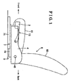
- Fig. 1 is a side view illustrating a seat for a vehicle according to an embodiment of the present invention
- Fig. 2 is a perspective view illustrating a positioning apparatus of a seat for a vehicle and a seat slide adjusting apparatus according to the embodiment;
- Fig. 3 is an exploded perspective view illustrating the positioning apparatus of the seat for the vehicle according to the embodiment
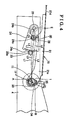
- Fig. 4 is a front view illustrating the positioning apparatus of the seat for the vehicle, provided at a lower frame, according to the embodiment
- Fig. 5 is an exploded perspective view illustrating the lower frame, an arm, a rotational member and a shaft pin according to the embodiment
- Fig. 6 is a front view illustrating the arm, the rotational member and the shaft pin when a rotational hole portion is moved to a central position;
- Fig. 7 is a front view illustrating the arm, the rotational member and the shaft pin when a rotational hole portion is moved to uppermost and bottommost positions;
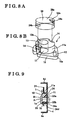
- Fig. 8 is a perspective view illustrating the rotational member, for indicating relationship between the rotational member and a sliding surface of the arm, and
- Fig. 9 is a cross-sectional view illustrating the positioning apparatus of the seat for the vehicle, taken along line IX-IX in Fig. 4 .
- FIG. 15 An embodiment of a positioning apparatus of a seat for a vehicle, which is indicated by reference numeral 15 (hereinafter referred to as a seat positioning apparatus 15), will be described hereinbelow with reference to the attached drawings.
- Arrows indicating Front, Back, R and L in Figs. 1 and 2 respectively correspond to directions of a front side, a back side, a right side and a left side of a vehicle seat 8 (a seat) when seen by an occupant seated thereon.
- directions of the positioning apparatus (and components thereof) in the embodiment correspond to the orientation of the vehicle seat 8 described above.
- the vehicle seat 8 includes a seat cushion 81 on which the occupant is seated, and a seat back 82 which is provided at the back portion of the seat cushion 81 for supporting a back of the occupant when he/she is seated.
- the seat positioning apparatus 15 adjusts a position of the seat cushion 81 in a vertical direction (i.e., an upper and lower direction). On the other hand, a position of the seat cushion 81 in the front-rear direction is adjusted by a seat slide adjusting apparatus 7.
- the seat slide adjusting apparatus 7 includes left and right lower rails 71 and left and right upper rails 72 (which serve as a member provided on a vehicle floor 9).
- Each of the lower rails 71 is an elongated member extending in the front-rear direction (in the front-rear direction of the vehicle seat 8) and is fixed at the vehicle floor 9.
- a cross-section of each of the lower rail 71 is formed in a substantially U-shape. Left and right ends of each of the lower rails 71 when seen in the cross section are formed in a pair of first engaging flanges 71a.
- Each of the upper rails 72 is an elongated member extending in the front-rear direction and a cross-section thereof is formed in a reverse T-shape. Further, left and right ends of each of the upper rails 72, when seen in the cross section, are formed in a pair of second engaging flanges 72a. The second engaging flanges 72a of the upper rails 72 engage with the first engaging flanges 71a of the corresponding lower rails 71 so as to be slidable relative to each other in the front-rear direction. Therefore, the seat cushion 81 is arranged to be slidable in the front-rear direction and to be fixed and retained at a predetermined front-rear adjusted position by means of a lock mechanism. Left and right lower frames 4 are fixed on the left and right upper rails 72, respectively.
- the seat positioning apparatus 15 includes the left and right lower frames 4 (each of which serves as a first frame), a sub frame 3 (which serves as a second frame) and a link mechanism 2.
- the left and right lower frames 4 support left and right sides of the seat cushion 81.
- the sub frame 3 is pivotably supported by the lower frames 4 and provided between the lower frames 4 and the seat cushion 81 for vertically (upwardly and downwardly) pivotally supporting the seat cushion 81.
- the link mechanism 2 is linked (cooperatively connected) to the sub frame 3 and is operated so as to cause the sub frame 3 to pivot relative to the lower frames 4.
- the lower frames 4 are elongated members extending in the front-rear direction of the vehicle. An upper end portion and a lower end portion of each of the lower frames 4 are bent inwardly (i.e. in a direction towards a central portion of the seat cushion 81) so as to form a first upper flange portion 4d and a lower flange portion 4e. Each of the first upper flange portions 4d is connected to each of the lower flange portions 4e via each back flange portion 4f which is formed by inwardly bending a back portion of the corresponding lower frame 4.
- the left and right lower frames 4 are fixed at the left and right upper rails 72 by means of bolts 4g, respectively.
- the lower flange portions 4e of the lower flanges 4 are fixed at the corresponding upper rails 72 by means of the corresponding bolts 4g.
- a rotating shaft 45 penetrates through the back portions of the left and right lower frames 4.
- Back frames are assembled at left and right ends of the rotating shaft 45, respectively, so as to support the seat back 82.
- the sub frame 3 includes left and right arms 31 (each of which serves as a second frame) and a bracket 32.
- the left and right arms 31 are pivotably supported by the first upper flange portions 4d of the corresponding lower frames 4.
- the bracket 32 is fixed at front portions of the left and right arms 31 by welding, for example.
- Each of the arms 31 is an elongated member extending in the front-rear direction of the vehicle and includes a vertical wall portion 31e and a second upper flange portion 31d.
- the vertical wall portion 31e is assembled at an inner side of the lower frame 4 and the second upper flange portion 31d is formed by bending an upper end portion of the vertical wall portion 31e outwardly (i.e.
- Hinge hole portions 34 are respectively formed at back portions of the vertical wall portions 31e of the arms 31.
- Shaft pins 33 (each of which serves as a shaft portion) are respectively rotatably inserted through the hinge hole portions 34 of the corresponding arms 31 and are fixed at the corresponding lower frames 4.
- the left and right arms 31 are structured to pivot about the hinge hole portions 34 relative to the corresponding lower frames 4.
- rotational hole portions 36 are formed substantially at longitudinally intermediate portions of the corresponding arms 31. The rotational hole portions 36 are pivotally moved by means of the link mechanism 2.
- the link mechanism 2 includes a driving link member 24 (which serves as a link member), a driven link member 26 (which serves as a link member) and a torque rod 25.
- the driving link member 24 is provided at the right side R of the seat positioning apparatus 15.
- the driven link member 26 is provided at the left side L of the seat positioning apparatus 15.
- the torque rod 25, which extends in the right and left direction of the vehicle, is provided between the driving and driven link members 24 and 26. Further, right and left end portions of the torque rod 25 are supported by the driving and driven link members 24 and 26, respectively.
- a rotational torque generated at the driving link member 24 is transmitted to the driven link member 26 via the torque rod 25.
- the driving link member 24 is a sector gear formed in an arc shape expanding to be wider towards the back side. Further, the driving link member 24 includes a first gear portion 24a at a back end potion thereof. The first gear portion 24a engages with a second gear portion 23a of a pinion 23, which is connected to an electric motor 21 and an output shaft of a deceleration mechanism 22, so that the rotational torque is transmitted from the electric motor 21 to the pinion 23 via the deceleration mechanism 22.
- the electric motor 21, the deceleration mechanism 22 and the pinion 23 are fixed at the right lower frame 4 and structured so as to be started to move and stopped by manually operating an operating button.
- the driving link member 24 is arranged between the right lower frame 4 and the right arm 31 of the right sub frame 3 and pivotably supported relative to the right lower frame 4 and the right arm 31.
- the first gear portion 24a formed at the back end portion of the driving link member 24 is formed along an arc-shaped path defined about a first torque hole 24b .
- the driving link member 24 pivots about the first torque hole 24b (more specifically, about the torque rod 25 inserted into the first torque hole 24b).
- the right end portion of the torque rod 25 is inserted into the first torque hole 24b of the driving link member 24 and fixed thereat by welding, for example.
- the left end portion of the torque rod 25 is inserted into a second torque hole 26b of the driven link member 26 and fixed thereat by welding, for example.
- the driven link member 26 is formed in an elliptical shape (i.e., substantially an oval shape), which extends in the front-rear direction, and does not include a gear portion while the driving link member 24 includes the first gear portion 24a.
- First and second rotational holes 24c and 26c are formed at the driving link member 24 and the driven link member 26, respectively. More specifically, the first and second rotational holes 24c and 26c are provided at further backward positions than positions where the first and second torque holes 24b and 26b are respectively provided, so that the first and second rotational holes 24c and 26c are positioned facing each other in an axial direction of stepped pins 30.
- the stepped pins 30 are inserted into the first rotational hole 24c of the driving link member 24 and the second rotational hole 26c of the driven link member 26, respectively. Further, the stepped pins 30 are inserted into the rotational hole portions 36, which are respectively opened at the left and right arms 31, and tightened by means of nut members 30a. Thus, the driving link member 24 and the driven link member 26 are pivotably supported relative to the corresponding arms 31.
- a burred portion 34d is formed around the hinge hole portion 34 of each arm 31 so as to extend outwardly from the vertical wall portion 31e.
- a rotational member 1 is rotatably inserted and fitted into the hinge hole portion 34 (right and left rotational members 1 are provided at the right and left arms 31, respectively).
- the rotational member 1 includes a head portion 10, an eccentric shaft portion 11 and a shaft hole 13.
- a diameter of the rotational member 1 is larger than a diameter of the hinge hole portion 34.
- the eccentric shaft portion 11 is slidably inserted into the hinge hole portion 34.
- the shaft hole 13 is formed through the rotational member 1 in an axial direction of the shaft pin 33.
- the eccentric shaft portion 11 includes an inner circumferential surface 13a (which serves as a second rotational portion) and an outer circumferential surface 11a (which serves as a first rotational portion).
- the inner circumferential surface 13a is formed at a side wall surface of the shaft hole 13 and has a center thereof at a point A (which serves as a second rotational center).
- the outer surface 11a has a center thereof at a point B (which serves as a first rotational center) which differs in location from the point A (i.e.
- An intermediate portion 33a of the shaft pin 33 is rotatably inserted into the shaft hole 13.
- the intermediate portion 33a rotatably supports the inner circumferential surface 13a of the rotational member 1 relative to the shaft pin 33 by slidably contacting the inner circumferential surface 13a.
- the rotational member 1 rotates about the point A relative to the shaft pin 33.
- the shaft pin 33 is rotatably inserted at the arm 31, allowing the rotational member 1 to rotate about the point A relative to the arm 31.
- the outer circumferential surface 11a of the eccentric shaft portion 11 pivotally supports the arm 31 by slidably contacting a sliding contact surface 34a which is formed at a side wall surface of the hinge hole portion 34 of the arm 31.
- the arm 31 pivots, relative to the lower frame 4, about the point B which is the center of the outer circumferential surface 11a of the rotational member 1.
- Lowermost and uppermost positions of a center of the rotational hole 36, herein, are assigned to be C1 and C2, respectively.
- the center of the rotational hole 36 is located at C1.
- the center of the rotational hole 36 is located at C2.
- a central position between C1 and C2 is assigned to be C3.
- the point B is positioned on a line L3 connecting C3 and a point E (the first torque hole 24b), which is a pivot center of the driving link member 24. Therefore, when the rotational hole portion 36 is positioned at the lowermost position C1 or the uppermost position C2, the point B moves to a position b1 on the line L3. On the other hand, when the rotational hole portion 36 is positioned at the central position C3, the point B moves to a position b2 which is located at a backward position further than the position b1 on the line L3.
- L1 represents a line connecting the point B (the position b1) and the C1 of the center of the rotational hole 36.
- L2 represents a line connecting the point B (the position b1) and C2 of the center of the rotational hole 36.
- L3 represents a line connecting the point B (the position b2) and C3 of the center of the rotational hole 36
- Lengths of the lines L1, L2 and L3 are determined to be equal to each other. Therefore, a distance between the positions b1 and b2 is equal to a variable of a distance between the point B about which the arm 31 pivots and the rotational hole portion 36 which pivots on an arced path defined about the first torque hole 24b.
- the head portion 10 of the rotational member 1 includes an enlarged diameter portion 10a which is formed by partly enlarging the head 10 in a radial direction thereof.
- the enlarged diameter portion 10a includes a protruding portion 12 which protrudes towards the arm 31 (i.e. in the axial direction of the shaft pin 33).
- the arm 31 includes a first elongated hole (which serves as an elongated hole) 35 above the hinge hole portion 34.
- the elongated hole 35 extends for a predetermined distance along an arc-shaped path defined about the point B (which is the pivot center of the outer circumferential surface 11a).
- the elongated hole 35 includes a first length 35a which allows the rotational member 1 to rotate relative to the arm 31 within a predetermined angle range.
- pawl portions 14 are provided at the outer surface 11a of the rotational member 1 so as to protrude in a radial direction of the outer circumference surface 11a and are arranged so as to be opposite from each other in a circumferential direction of the outer surface 11a.
- Second elongated holes 34b are formed at the sliding contact surface 34a of the arm 31, respectively, so as to extend in a circumferential direction of the sliding surface 34a for a predetermined distance.
- the pawl portions 14 engage with the second elongated holes 34b of the rotational member 1, respectively.
- Each of the second elongated holes 34b includes a second length 34c which allows a pivotal movement of the corresponding pawl portion 14 when the rotational member 1 rotates within a predetermined angle range.
- the shaft pin 33 is inserted into the shaft hole 13 of the rotational member 1 and a leg portion 33b of the shaft pin 33 is inserted into the hole 4a of the lower frame 4.
- the leg portion 33b is caulked so that the shaft pin 33 is fixed at the lower frame 4.
- the rotational member 1 in the embodiment is made of resin, however, other components are made of metal.
- the arm 31 pivots about the point B which is located on the rotational member 1.
- the point B is located at a eccentric position relative to the point A which is the rotational center of the rotational member 1. Therefore, when the rotational hole portion 36 pivots along the arc-shaped path, a position of the point B relative to the point A is changed. As a result, displacement of the pivot center of the arm 31 relative to the lower frame 4 is offset. Therefore, the arm 31 smoothly pivots relative to the lower frame 4.
- the seat positioning apparatus 15 includes the rotational member 1 which rotatably supports the arm 31 and which is rotatably supported relative to the lower frame 4 of the seat 8.
- the rotational member 1 includes the eccentric shaft portion 11, at which the pivot center (the point B) of the arm 31 pivoting relative to the lower frame 4 is eccentrically located relative to the rotational center (the point A) of the rotational member 1 rotating relative to the lower frame 4.
- the pivot center (the point B) of the arm 31 which rotates relative to the lower frame 4 is moved relative to the rotational center (the point A) of the rotational member 1.
- the arm 31 is rotatably supported at the lower frame 4 and operatively connected to the driving link member 24 at the rotational hole portion 36. Therefore, the arm 31 and the driving link member 24 pivot smoothly.
- the other arm (left arm) 31 linked to the driven link member 26 is cooperatively pivoted in association with the movement of the right arm 31 in the same manner as described above.
- the rotational member 1 is rotatably supported relative to the lower frame 4 and the rotational member 1 rotatably supports the arm 31. Therefore, dimensions where the rotational member 1 contacts the lower frame 4 and the arm 31 are sufficiently obtained. As a result, when the arm 31 receives an external load, for example, when an occupant is seated thereon, backlash is not generated and the arm 31 is surely rotatably supported relative to the lower frame 4.
- the seat positioning apparatus 15 is structured so that the rotational member 1 is provided between the lower frame 4 and the arm 31, the structure of the seat positioning apparatus 15 is simplified. Therefore, the number of components is reduced compared to an seat positioning apparatus where another link member is provided in order to prevent the backlash generated when receiving the external load.
- the rotational member 1 is slidably supported by the shaft pin 33 at the inner circumferential surface 13a of the rotational member 1 fixed at the lower frame 4, and the rotational member 1 slidably supports the arm 31 by the outer circumferential surface 11a of the rotational member 1. Therefore, the rotational member 1 is in a stably and rotatably supportive relationship relative to the shaft pin 33 and the arm 31 by means of a whole circumference of the inner circumferential surface 13a of the eccentric shaft portion 11 and a whole circumference of the outer circumferential surface 11a of the eccentric shaft portion 11. Therefore, the arm 31 smoothly and stably pivots relative to the lower frame 4.
- the protruding portion 12 which protrudes from the rotational member 1 is inserted into the first elongated hole 35 of the arm 31. Therefore, the rotational member 1 is surely assembled to the arm 31 without falsely arranging a direction in which the point B is positioned eccentrically relative to the point A.
- the outer circumferential surface 11a of the rotational member 1 includes the pawl portions 14 which engage with the arm 31. By respectively engaging the pawl portions 14 with the second elongated holes 34b formed at the sliding contact surface 34a of the arm 31, the rotational member 1 is prevented from released from the arm 31. Therefore, components are easily assembled.
- the rotational member 1 is made of resin. Therefore, compared to a rotational member made of high-rigid metal, the rotational member 1 slidably pivots tightly and smoothly relative to the shaft pin 33 and the arm 31.
- the point B is positioned on a line L3 connecting a point E (the first torque hole 24b) which is a pivot center of the driving link member 24 and an central position C3 located between the lowermost position C1 and the uppermost position C2 of the third rotating hole 36 of the arm 31. Therefore, the point B reciprocates substantially in a straight manner between the position b1 and the position b2 located on the line L3.
- the point B is not necessarily positioned on the line L3 and may be positioned at another position. In such a case, the path of the point B is not defined in a straight manner.
- a positional relationship between the point A and the point B is not limited as described in the above-described embodiment.
- the point B may be located at a more downward position than the position where the point A is located. Further, for example, the point B may be located either upwardly or downwardly further than the point A and either frontwardly or rearwardly further than the point A. Moreover, a distance between the point A and the point B may be changed.
- the protruding portion 12 for determining an assembling position is formed in an eccentric direction, i.e. in a direction in which the point B is located eccentrically relative to the point A of the rotational center of the rotational member 1.
- the position of the protruding portion 12 is not limited to the position described above.
- the protruding portion 12 may be provided at any other position located in a circumference direction of the rotational member 1.
- a positioning apparatus of a seat for a vehicle includes a first frame (4) adapted to be supported by a member (71, 72) provided on a vehicle floor (9) and adapted to support a seat cushion (81), a second frame (3) rotatably supported by the first frame (4) and vertically rotatably supporting the seat cushion (81), a link member (24, 26) rotatably supported by the first frame (4) and linked to the second frame (3) for rotatably moving the second frame (3) relative to the first frame (4), and a rotational member (1) rotatably supported by the first frame (4) and including an eccentric shaft portion (11), wherein the eccentric shaft portion (11) has a first rotational portion (11a) including a first rotational center (B) about which the second frame (3) rotates relative to the first frame (4) and a second rotational portion (13a) including a second rotational center (A) about which the
Landscapes
- Engineering & Computer Science (AREA)
- Aviation & Aerospace Engineering (AREA)
- Transportation (AREA)
- Mechanical Engineering (AREA)
- Seats For Vehicles (AREA)
Abstract
Description
- The present invention relates to a positioning apparatus of a seat for a vehicle.
- A known positioning apparatus of a seat cushion for a vehicle disclosed in
JP2001-219767A reference 1, in order to offset the displacement, an elongated hole is provided at the lower frame for slidably moving a pin fixed at the link member in a horizontal direction relative to the lower frame. - However, because the pin horizontally slides inside the elongated hole, a contacting portion between the pin and the elongated hole may be small. Accordingly, in a condition where the seat cushion receives an external load, for example, when an occupant is seated thereon, backlash may be generated at the positioning apparatus of the seat cushion for the vehicle. Another link member may be provided between the link member and the sub frame in order to prevent the backlash. However, in such a way, the number of components of the seat positioning apparatus may be increased.
- A need thus exists for a positioning apparatus of a seat for a vehicle, of which a link member and a sub frame smoothly rotate without generating backlash even when receiving external load, and which restrains the number of components.
- According to an aspect of the present invention, a positioning apparatus of a seat for a vehicle includes a first frame adapted to be supported by a member provided on a vehicle floor and adapted to support a seat cushion of the seat, a second frame rotatably supported by the first frame and adapted to vertically rotatably support the seat cushion, a link member rotatably supported by the first frame and linked to the second frame for rotatably moving the second frame relative to the first frame, and a rotational member rotatably supported by the first frame and including an eccentric shaft portion, wherein the eccentric shaft portion has a first rotational portion including a first rotational center about which the second frame rotates relative to the first frame and a second rotational portion including a second rotational center about which the rotational member rotates relative to the first frame and which is eccentrically provided relative to the first rotational center.
- Accordingly, the seat positioning apparatus includes the rotational member which rotatably supports the second frame and which is rotatably supported relative to the first frame of the seat. The rotational member includes the eccentric shaft portion, at which the first rotational center of the second frame rotating relative to the first frame is eccentrically located relative to the second rotational center of the rotational member rotating relative to the first frame. When the second frame rotates relative to the first frame, the first rotational center of the second frame which rotates relative to the first frame is moved relative to the second rotational center of the
rotational member 1. As a result, displacement of the second rotational center of the second frame relative to the first frame is offset. - Further, the rotational member is rotatably supported relative to the first frame and the rotational member rotatably supports the second frame. Therefore, dimensions where the rotational member contacts the first frame and the second frame are sufficiently obtained. As a result, when the second frame receives an external load, for example, when an occupant is seated thereon, backlash is not generated and the second frame is surely rotatably supported relative to the
first frame 4. - Still further, because the positioning apparatus of a seat for a vehicle is structured so that the rotational member is provided between the first frame and the second frame, the structure of the positioning apparatus of a seat for a vehicle is simplified. Therefore, the number of components is reduced compared to an seat positioning apparatus where another link member is provided in order to prevent the backlash generated when receiving the external load
- According to another aspect of the invention, the first rotational portion of the eccentric shaft portion includes an outer circumferential surface rotatably contacting and supporting the second frame relative to the first frame, and the second rotational portion of the eccentric shaft portion includes an inner circumferential surface rotatably contacted and supported relative to a shaft portion fixed at the first frame for rotatably supporting the rotational member relative to the first frame.
- Accordingly, the rotational member is slidably supported by the shaft portion at the inner circumferential surface of the rotational member fixed at the first frame, and the rotational member slidably supports the second frame by the outer circumferential surface of the rotational member. Therefore, the rotational member is in a stably and rotatably supportive relationship relative to the shaft portion and the secibd frame by means of a whole circumference of the inner circumferential surface of the eccentric shaft portion and a whole circumference of the outer circumferential surface of the eccentric shaft portion. Therefore, the second frame smoothly and stably pivots relative to the first frame.
- According to another aspect of the invention, the rotational member includes a protruding portion provided at a position radially further outwardly than the outer circumferential surface and protruding into the second frame, and the second frame includes an elongated hole extending along an arc-shaped path defined about the first rotational center so that the protruding portion of the rotational member is rotatably movably engaged into the elongated hole.
- Accordingly, when assembling the rotational member to the second frame, the protruding portion which protrudes from the rotational member is inserted into the first elongated hole of the second frame. Therefore, the rotational member is surely assembled to the second frame without falsely arranging a direction in which the first rotational center is positioned eccentrically relative to the second rotational center.
- According to another aspect of the invention, the outer circumferential surface of the rotational member includes a pawl portion engaged with the second frame.
- Accordingly, by respectively engaging the pawl portions with the second elongated holes formed at the sliding contact surface of the second frame, the rotational member is prevented from released from the second frame. Therefore, components are easily assembled.
- According to another aspect of the invention, the rotational member is made of resin.
- Accordingly, compared to a rotational member made of high-rigid metal, the rotational member slidably rotates tightly and smoothly relative to the shaft portion and the second frame.
- The foregoing and additional features and characteristics of the present invention will become more apparent from the following detailed description considered with the reference to the accompanying drawings, wherein:
-
Fig. 1 is a side view illustrating a seat for a vehicle according to an embodiment of the present invention; -
Fig. 2 is a perspective view illustrating a positioning apparatus of a seat for a vehicle and a seat slide adjusting apparatus according to the embodiment; -
Fig. 3 is an exploded perspective view illustrating the positioning apparatus of the seat for the vehicle according to the embodiment; -
Fig. 4 is a front view illustrating the positioning apparatus of the seat for the vehicle, provided at a lower frame, according to the embodiment; -
Fig. 5 is an exploded perspective view illustrating the lower frame, an arm, a rotational member and a shaft pin according to the embodiment; -
Fig. 6 is a front view illustrating the arm, the rotational member and the shaft pin when a rotational hole portion is moved to a central position; -
Fig. 7 is a front view illustrating the arm, the rotational member and the shaft pin when a rotational hole portion is moved to uppermost and bottommost positions; -
Fig. 8 is a perspective view illustrating the rotational member, for indicating relationship between the rotational member and a sliding surface of the arm, and -
Fig. 9 is a cross-sectional view illustrating the positioning apparatus of the seat for the vehicle, taken along line IX-IX inFig. 4 . - An embodiment of a positioning apparatus of a seat for a vehicle, which is indicated by reference numeral 15 (hereinafter referred to as a seat positioning apparatus 15), will be described hereinbelow with reference to the attached drawings. Arrows indicating Front, Back, R and L in
Figs. 1 and2 respectively correspond to directions of a front side, a back side, a right side and a left side of a vehicle seat 8 (a seat) when seen by an occupant seated thereon. Also, hereinbelow, directions of the positioning apparatus (and components thereof) in the embodiment correspond to the orientation of the vehicle seat 8 described above. The vehicle seat 8 includes aseat cushion 81 on which the occupant is seated, and aseat back 82 which is provided at the back portion of theseat cushion 81 for supporting a back of the occupant when he/she is seated. Theseat positioning apparatus 15 according the embodiment adjusts a position of theseat cushion 81 in a vertical direction (i.e., an upper and lower direction). On the other hand, a position of theseat cushion 81 in the front-rear direction is adjusted by a seat slide adjusting apparatus 7. - The seat slide adjusting apparatus 7 includes left and right
lower rails 71 and left and right upper rails 72 (which serve as a member provided on a vehicle floor 9). Each of thelower rails 71 is an elongated member extending in the front-rear direction (in the front-rear direction of the vehicle seat 8) and is fixed at the vehicle floor 9. As illustrated inFig. 2 , a cross-section of each of thelower rail 71 is formed in a substantially U-shape. Left and right ends of each of thelower rails 71 when seen in the cross section are formed in a pair of firstengaging flanges 71a. Each of theupper rails 72 is an elongated member extending in the front-rear direction and a cross-section thereof is formed in a reverse T-shape. Further, left and right ends of each of theupper rails 72, when seen in the cross section, are formed in a pair of secondengaging flanges 72a. The secondengaging flanges 72a of theupper rails 72 engage with the firstengaging flanges 71a of the correspondinglower rails 71 so as to be slidable relative to each other in the front-rear direction. Therefore, theseat cushion 81 is arranged to be slidable in the front-rear direction and to be fixed and retained at a predetermined front-rear adjusted position by means of a lock mechanism. Left and rightlower frames 4 are fixed on the left and rightupper rails 72, respectively. - As illustrated in
Figs. 1 and2 , theseat positioning apparatus 15 includes the left and right lower frames 4 (each of which serves as a first frame), a sub frame 3 (which serves as a second frame) and alink mechanism 2. The left and rightlower frames 4 support left and right sides of theseat cushion 81. Thesub frame 3 is pivotably supported by thelower frames 4 and provided between thelower frames 4 and theseat cushion 81 for vertically (upwardly and downwardly) pivotally supporting theseat cushion 81. Thelink mechanism 2 is linked (cooperatively connected) to thesub frame 3 and is operated so as to cause thesub frame 3 to pivot relative to the lower frames 4. - The
lower frames 4 are elongated members extending in the front-rear direction of the vehicle. An upper end portion and a lower end portion of each of thelower frames 4 are bent inwardly (i.e. in a direction towards a central portion of the seat cushion 81) so as to form a firstupper flange portion 4d and alower flange portion 4e. Each of the firstupper flange portions 4d is connected to each of thelower flange portions 4e via eachback flange portion 4f which is formed by inwardly bending a back portion of the correspondinglower frame 4. The left and rightlower frames 4 are fixed at the left and rightupper rails 72 by means ofbolts 4g, respectively. More specifically, thelower flange portions 4e of thelower flanges 4 are fixed at the correspondingupper rails 72 by means of the correspondingbolts 4g. A rotatingshaft 45 penetrates through the back portions of the left and right lower frames 4. Back frames are assembled at left and right ends of therotating shaft 45, respectively, so as to support the seat back 82. - As illustrated in
Figs. 2 and3 , thesub frame 3 includes left and right arms 31 (each of which serves as a second frame) and abracket 32. The left andright arms 31 are pivotably supported by the firstupper flange portions 4d of the correspondinglower frames 4. Thebracket 32 is fixed at front portions of the left andright arms 31 by welding, for example. Each of thearms 31 is an elongated member extending in the front-rear direction of the vehicle and includes avertical wall portion 31e and a secondupper flange portion 31d. Thevertical wall portion 31e is assembled at an inner side of thelower frame 4 and the secondupper flange portion 31d is formed by bending an upper end portion of thevertical wall portion 31e outwardly (i.e. in a direction away from the central portion of the seat cushion 81) and is mounted on the firstupper flange portion 4d of thelower frame 4.Hinge hole portions 34 are respectively formed at back portions of thevertical wall portions 31e of thearms 31. Shaft pins 33 (each of which serves as a shaft portion) are respectively rotatably inserted through thehinge hole portions 34 of the correspondingarms 31 and are fixed at the correspondinglower frames 4. Thus, the left andright arms 31 are structured to pivot about thehinge hole portions 34 relative to the correspondinglower frames 4. Further,rotational hole portions 36 are formed substantially at longitudinally intermediate portions of the correspondingarms 31. Therotational hole portions 36 are pivotally moved by means of thelink mechanism 2. - As illustrated in
Fig. 2 , thelink mechanism 2 includes a driving link member 24 (which serves as a link member), a driven link member 26 (which serves as a link member) and atorque rod 25. The drivinglink member 24 is provided at the right side R of theseat positioning apparatus 15. The drivenlink member 26 is provided at the left side L of theseat positioning apparatus 15. Thetorque rod 25, which extends in the right and left direction of the vehicle, is provided between the driving and drivenlink members torque rod 25 are supported by the driving and drivenlink members link member 24 is transmitted to the drivenlink member 26 via thetorque rod 25. - The driving
link member 24 is a sector gear formed in an arc shape expanding to be wider towards the back side. Further, the drivinglink member 24 includes afirst gear portion 24a at a back end potion thereof. Thefirst gear portion 24a engages with asecond gear portion 23a of apinion 23, which is connected to anelectric motor 21 and an output shaft of adeceleration mechanism 22, so that the rotational torque is transmitted from theelectric motor 21 to thepinion 23 via thedeceleration mechanism 22. Theelectric motor 21, thedeceleration mechanism 22 and thepinion 23 are fixed at the rightlower frame 4 and structured so as to be started to move and stopped by manually operating an operating button. The drivinglink member 24 is arranged between the rightlower frame 4 and theright arm 31 of theright sub frame 3 and pivotably supported relative to the rightlower frame 4 and theright arm 31. Thefirst gear portion 24a formed at the back end portion of the drivinglink member 24 is formed along an arc-shaped path defined about afirst torque hole 24b . When thesecond gear portion 23a of thepinion 23 rotates on thefirst gear portion 24a, the drivinglink member 24 pivots about thefirst torque hole 24b (more specifically, about thetorque rod 25 inserted into thefirst torque hole 24b). The right end portion of thetorque rod 25 is inserted into thefirst torque hole 24b of the drivinglink member 24 and fixed thereat by welding, for example. Likewise, the left end portion of thetorque rod 25 is inserted into asecond torque hole 26b of the drivenlink member 26 and fixed thereat by welding, for example. The right and left end portions of thetorque rod 25, which respectively protrude further outwardly than positions at thetorque rod 25 where the driving and drivenlink members holes 4b of the right and leftlower frames 4, respectively. - The driven
link member 26 is formed in an elliptical shape (i.e., substantially an oval shape), which extends in the front-rear direction, and does not include a gear portion while the drivinglink member 24 includes thefirst gear portion 24a. First and secondrotational holes link member 24 and the drivenlink member 26, respectively. More specifically, the first and secondrotational holes rotational holes rotational hole 24c of the drivinglink member 24 and the secondrotational hole 26c of the drivenlink member 26, respectively. Further, the stepped pins 30 are inserted into therotational hole portions 36, which are respectively opened at the left andright arms 31, and tightened by means ofnut members 30a. Thus, the drivinglink member 24 and the drivenlink member 26 are pivotably supported relative to the correspondingarms 31. - As illustrated in
Figs. 4 and5 , when the driving and drivenlink members right arms 31 rotate about the correspondingbinge hole portions 34. Structures and functions of the left and right sides of theseat positioning apparatus 15 are substantially the same, therefore, right side of theseat positioning apparatus 15 is mainly described hereinbelow as an example. A burredportion 34d is formed around thehinge hole portion 34 of eacharm 31 so as to extend outwardly from thevertical wall portion 31e. Further, arotational member 1 is rotatably inserted and fitted into the hinge hole portion 34 (right and leftrotational members 1 are provided at the right and leftarms 31, respectively). Therotational member 1 includes ahead portion 10, aneccentric shaft portion 11 and ashaft hole 13. A diameter of therotational member 1 is larger than a diameter of thehinge hole portion 34. Theeccentric shaft portion 11 is slidably inserted into thehinge hole portion 34. Theshaft hole 13 is formed through therotational member 1 in an axial direction of theshaft pin 33. Theeccentric shaft portion 11 includes an innercircumferential surface 13a (which serves as a second rotational portion) and an outercircumferential surface 11a (which serves as a first rotational portion). The innercircumferential surface 13a is formed at a side wall surface of theshaft hole 13 and has a center thereof at a point A (which serves as a second rotational center). Theouter surface 11a has a center thereof at a point B (which serves as a first rotational center) which differs in location from the point A (i.e. a position where the point B is located is different from a position where the point A is located.) Anintermediate portion 33a of theshaft pin 33 is rotatably inserted into theshaft hole 13. Theintermediate portion 33a rotatably supports the innercircumferential surface 13a of therotational member 1 relative to theshaft pin 33 by slidably contacting the innercircumferential surface 13a. Therotational member 1 rotates about the point A relative to theshaft pin 33. Theshaft pin 33 is rotatably inserted at thearm 31, allowing therotational member 1 to rotate about the point A relative to thearm 31. - The outer
circumferential surface 11a of theeccentric shaft portion 11 pivotally supports thearm 31 by slidably contacting a slidingcontact surface 34a which is formed at a side wall surface of thehinge hole portion 34 of thearm 31. Thearm 31 pivots, relative to thelower frame 4, about the point B which is the center of the outercircumferential surface 11a of therotational member 1. Lowermost and uppermost positions of a center of therotational hole 36, herein, are assigned to be C1 and C2, respectively. When thearm 31 reaches a lowermost position thereof, the center of therotational hole 36 is located at C1. When thearm 31 reaches an uppermost position thereof, the center of therotational hole 36 is located at C2. Further, a central position between C1 and C2 is assigned to be C3. The point B is positioned on a line L3 connecting C3 and a point E (thefirst torque hole 24b), which is a pivot center of the drivinglink member 24. Therefore, when therotational hole portion 36 is positioned at the lowermost position C1 or the uppermost position C2, the point B moves to a position b1 on the line L3. On the other hand, when therotational hole portion 36 is positioned at the central position C3, the point B moves to a position b2 which is located at a backward position further than the position b1 on the line L3. Herein, L1 represents a line connecting the point B (the position b1) and the C1 of the center of therotational hole 36. L2 represents a line connecting the point B (the position b1) and C2 of the center of therotational hole 36. Likewise, L3 represents a line connecting the point B (the position b2) and C3 of the center of therotational hole 36 Lengths of the lines L1, L2 and L3 are determined to be equal to each other. Therefore, a distance between the positions b1 and b2 is equal to a variable of a distance between the point B about which thearm 31 pivots and therotational hole portion 36 which pivots on an arced path defined about thefirst torque hole 24b. - As illustrated in
Figs. 5 ,6 ,7 , and8 , thehead portion 10 of therotational member 1 includes anenlarged diameter portion 10a which is formed by partly enlarging thehead 10 in a radial direction thereof. Theenlarged diameter portion 10a includes a protrudingportion 12 which protrudes towards the arm 31 (i.e. in the axial direction of the shaft pin 33). Thearm 31 includes a first elongated hole (which serves as an elongated hole) 35 above thehinge hole portion 34. As illustrated inFigs. 6 and 7 , theelongated hole 35 extends for a predetermined distance along an arc-shaped path defined about the point B (which is the pivot center of the outercircumferential surface 11a). Further, theelongated hole 35 includes afirst length 35a which allows therotational member 1 to rotate relative to thearm 31 within a predetermined angle range. - As illustrated in
Fig. 8 ,pawl portions 14 are provided at theouter surface 11a of therotational member 1 so as to protrude in a radial direction of theouter circumference surface 11a and are arranged so as to be opposite from each other in a circumferential direction of theouter surface 11a. Secondelongated holes 34b are formed at the slidingcontact surface 34a of thearm 31, respectively, so as to extend in a circumferential direction of the slidingsurface 34a for a predetermined distance. Thepawl portions 14 engage with the secondelongated holes 34b of therotational member 1, respectively. Each of the secondelongated holes 34b includes asecond length 34c which allows a pivotal movement of thecorresponding pawl portion 14 when therotational member 1 rotates within a predetermined angle range. - As illustrated in
Figs. 5 ,6 ,7 , and8 , when assembling thearm 31 and therotational member 1 to thelower frame 4, first, theeccentric shaft portion 11 of therotational member 1 is inserted into thehinge hole portion 34 of thearm 31 and the protrudingportion 12 of therotational member 1 is engaged into the firstelongated hole 35. By inserting therotational member 1 into thehinge hole portion 34, thepawl portions 14 formed at theouter surface 11a of therotational member 1 respectively engage with the secondelongated holes 34b formed at the slidingsurface 34a of thearm 31, thus therotational member 1 is assembled onto thearm 31. Second, theshaft pin 33 is inserted into theshaft hole 13 of therotational member 1 and aleg portion 33b of theshaft pin 33 is inserted into thehole 4a of thelower frame 4. Third, as illustrated inFig. 9 , theleg portion 33b is caulked so that theshaft pin 33 is fixed at thelower frame 4. Further, therotational member 1 in the embodiment is made of resin, however, other components are made of metal. - An operation of the
seat positioning apparatus 15 according to the embodiment will be described hereinbelow. When the operating button is manually operated, as illustrated inFig. 2 , theelectric motor 21 starts to rotate and thedecelerating mechanism 22 decelerates a rotating speed (rotational torque) of theelectric motor 21. Then, the rotational torque is transmitted to thepinion 23, and then thepinion 23 is operated to rotate. Then, by means of the rotation of thepinion 23, the drivinglink member 24 pivots about the point E of thefirst torque hole 24b relative to thelower frame 4. Because thetorque rod 25 is inserted into and fixed at thefirst torque hole 24b, thetorque rod 25 is rotated by the rotation of thefirst link member 24. Therefore, the rotational torque is transmitted to the drivenlink member 26. Thus, the drivinglink member 24 and the drivenlink member 26 pivot synchronously. - As illustrated in
Figs. 2 and3 , when the drivinglink member 24 and the drivenlink member 26 pivot, the left andright arms 31,which are rotatably supported by the left and rightrotational hole portions 36, pivot relative to thelower frame 4. Operations of the drivinglink member 24 and the drivenlink member 26 are substantially the same. Therefore, the operation of the drivinglink member 24 is described hereinbelow as an example. As illustrated inFig. 4 , when the drivinglink member 24 pivots downwardly by means of the rotation of thepinion 23, thearm 31 pivots downwardly. Likewise, when the drivinglink member 24 rotates upwardly by means of the rotation of thepinion 23, thearm 31 pivots upwardly. Therotational hole portion 36 of thearm 31 pivots on an arc-shaped path defined about the point E of the torque hole. Then, thearm 31 pivots about the point B which is located on therotational member 1. The point B is located at a eccentric position relative to the point A which is the rotational center of therotational member 1. Therefore, when therotational hole portion 36 pivots along the arc-shaped path, a position of the point B relative to the point A is changed. As a result, displacement of the pivot center of thearm 31 relative to thelower frame 4 is offset. Therefore, thearm 31 smoothly pivots relative to thelower frame 4. - The
seat positioning apparatus 15 according to the embodiment includes therotational member 1 which rotatably supports thearm 31 and which is rotatably supported relative to thelower frame 4 of the seat 8. Therotational member 1 includes theeccentric shaft portion 11, at which the pivot center (the point B) of thearm 31 pivoting relative to thelower frame 4 is eccentrically located relative to the rotational center (the point A) of therotational member 1 rotating relative to thelower frame 4. When thearm 31 pivots relative to thelower frame 4, the pivot center (the point B) of thearm 31 which rotates relative to thelower frame 4 is moved relative to the rotational center (the point A) of therotational member 1. Further, thearm 31 is rotatably supported at thelower frame 4 and operatively connected to the drivinglink member 24 at therotational hole portion 36. Therefore, thearm 31 and the drivinglink member 24 pivot smoothly. The other arm (left arm) 31 linked to the drivenlink member 26 is cooperatively pivoted in association with the movement of theright arm 31 in the same manner as described above. - Further, the
rotational member 1 is rotatably supported relative to thelower frame 4 and therotational member 1 rotatably supports thearm 31. Therefore, dimensions where therotational member 1 contacts thelower frame 4 and thearm 31 are sufficiently obtained. As a result, when thearm 31 receives an external load, for example, when an occupant is seated thereon, backlash is not generated and thearm 31 is surely rotatably supported relative to thelower frame 4. - Still further, because the
seat positioning apparatus 15 is structured so that therotational member 1 is provided between thelower frame 4 and thearm 31, the structure of theseat positioning apparatus 15 is simplified. Therefore, the number of components is reduced compared to an seat positioning apparatus where another link member is provided in order to prevent the backlash generated when receiving the external load. - Furthermore, the
rotational member 1 is slidably supported by theshaft pin 33 at the innercircumferential surface 13a of therotational member 1 fixed at thelower frame 4, and therotational member 1 slidably supports thearm 31 by the outercircumferential surface 11a of therotational member 1. Therefore, therotational member 1 is in a stably and rotatably supportive relationship relative to theshaft pin 33 and thearm 31 by means of a whole circumference of the innercircumferential surface 13a of theeccentric shaft portion 11 and a whole circumference of the outercircumferential surface 11a of theeccentric shaft portion 11. Therefore, thearm 31 smoothly and stably pivots relative to thelower frame 4. - Still further, when assembling the
rotational member 1 to thearm 31, the protrudingportion 12 which protrudes from therotational member 1 is inserted into the firstelongated hole 35 of thearm 31. Therefore, therotational member 1 is surely assembled to thearm 31 without falsely arranging a direction in which the point B is positioned eccentrically relative to the point A. Further, the outercircumferential surface 11a of therotational member 1 includes thepawl portions 14 which engage with thearm 31. By respectively engaging thepawl portions 14 with the secondelongated holes 34b formed at the slidingcontact surface 34a of thearm 31, therotational member 1 is prevented from released from thearm 31. Therefore, components are easily assembled. - Furthermore, the
rotational member 1 is made of resin. Therefore, compared to a rotational member made of high-rigid metal, therotational member 1 slidably pivots tightly and smoothly relative to theshaft pin 33 and thearm 31. - According to the embodiment, the point B is positioned on a line L3 connecting a point E (the
first torque hole 24b) which is a pivot center of the drivinglink member 24 and an central position C3 located between the lowermost position C1 and the uppermost position C2 of the thirdrotating hole 36 of thearm 31. Therefore, the point B reciprocates substantially in a straight manner between the position b1 and the position b2 located on the line L3. However, the point B is not necessarily positioned on the line L3 and may be positioned at another position. In such a case, the path of the point B is not defined in a straight manner. Further, a positional relationship between the point A and the point B is not limited as described in the above-described embodiment. Alternatively, for example, the point B may be located at a more downward position than the position where the point A is located. Further, for example, the point B may be located either upwardly or downwardly further than the point A and either frontwardly or rearwardly further than the point A. Moreover, a distance between the point A and the point B may be changed. - Further, according to the embodiment, the protruding
portion 12 for determining an assembling position is formed in an eccentric direction, i.e. in a direction in which the point B is located eccentrically relative to the point A of the rotational center of therotational member 1. However, the position of the protrudingportion 12 is not limited to the position described above. Alternatively, the protrudingportion 12 may be provided at any other position located in a circumference direction of therotational member 1. - Still further, according to the embodiment, the rotational torque is generated by means of the
electric motor 21. However, the rotational torque may be generated manually. A positioning apparatus of a seat for a vehicle includes a first frame (4) adapted to be supported by a member (71, 72) provided on a vehicle floor (9) and adapted to support a seat cushion (81), a second frame (3) rotatably supported by the first frame (4) and vertically rotatably supporting the seat cushion (81), a link member (24, 26) rotatably supported by the first frame (4) and linked to the second frame (3) for rotatably moving the second frame (3) relative to the first frame (4), and a rotational member (1) rotatably supported by the first frame (4) and including an eccentric shaft portion (11), wherein the eccentric shaft portion (11) has a first rotational portion (11a) including a first rotational center (B) about which the second frame (3) rotates relative to the first frame (4) and a second rotational portion (13a) including a second rotational center (A) about which the rotational member (1) rotates relative to the first frame (4) and which is eccentrically provided relative to the first rotational center (B).
Claims (5)
- A positioning apparatus (15) of a seat for a vehicle comprising:a first frame (4) adapted to be supported by a member (71, 72) provided on a vehicle floor (9) and adapted to support a seat cushion (81) of the seat (8);a second frame (3) rotatably supported by the first frame (4) and adapted to vertically rotatably support the seat cushion (81);a link member (24, 26) rotatably supported by the first frame (4) and linked to the second frame (3) for rotatably moving the second frame (3) relative to the first frame (4); anda rotational member (1) rotatably supported by the first frame (4) and including an eccentric shaft portion (11), whereinthe eccentric shaft portion (11) has a first rotational portion (11a) including a first rotational center (B) about which the second frame (3) rotates relative to the first frame (4) and a second rotational portion (13a) including a second rotational center (A) about which the rotational member (1) rotates relative to the first frame (4) and which is eccentrically provided relative to the first rotational center (B).
- A positioning apparatus of a seat for a vehicle according to claim 1, wherein the first rotational portion (11a) of the eccentric shaft portion (11) includes an outer circumferential surface rotatably contacting and supporting the second frame (3) relative to the first frame (4), and the second rotational portion (13a) of the eccentric shaft portion (11) includes an inner circumferential surface rotatably contacted and supported relative to a shaft portion (33a) fixed at the first frame (4) for rotatably supporting the rotational member(1) relative to the first frame (4).
- A positioning apparatus of a seat for a vehicle according to claim 2, wherein the rotational member (1) includes a protruding portion (12) provided at a position radially further outwardly than the outer circumferential surface (11a) and protruding into the second frame (3), and wherein the second frame (3) includes an elongated hole (35) extending along an are-shaped path defined about the first rotational center (B) so that the protruding portion (12) of the rotational member (1) is rotatably movably engaged into the elongated hole (35).
- A positioning apparatus of a seat for a vehicle according to any of claims 2 and 3, wherein the outer circumferential surface (11a) of the rotational member (1) includes a pawl portion (14) engaged with the second frame (3).
- A positioning apparatus of a seat for a vehicle according to any of claims 1 to 4, wherein the rotational member (1) is made of resin.
Applications Claiming Priority (1)
| Application Number | Priority Date | Filing Date | Title |
|---|---|---|---|
| JP2007252718A JP2009083557A (en) | 2007-09-27 | 2007-09-27 | Vehicle seat vertical position adjustment device |
Publications (2)
| Publication Number | Publication Date |
|---|---|
| EP2042368A2 true EP2042368A2 (en) | 2009-04-01 |
| EP2042368A3 EP2042368A3 (en) | 2009-11-04 |
Family
ID=40328132
Family Applications (1)
| Application Number | Title | Priority Date | Filing Date |
|---|---|---|---|
| EP08165131A Withdrawn EP2042368A3 (en) | 2007-09-27 | 2008-09-25 | Positioning apparatus of seat for vehicle |
Country Status (3)
| Country | Link |
|---|---|
| US (1) | US20090085390A1 (en) |
| EP (1) | EP2042368A3 (en) |
| JP (1) | JP2009083557A (en) |
Families Citing this family (3)
| Publication number | Priority date | Publication date | Assignee | Title |
|---|---|---|---|---|
| JP2016060478A (en) * | 2014-09-19 | 2016-04-25 | 株式会社タチエス | Vehicle seat |
| DE102014219066B4 (en) * | 2014-09-22 | 2024-07-25 | Keiper Seating Mechanisms Co., Ltd. | Connection arrangement for a vehicle seat and vehicle seat |
| CN110774950B (en) * | 2019-10-29 | 2021-03-30 | 恺博(常熟)座椅机械部件有限公司 | a welcome slide |
Citations (1)
| Publication number | Priority date | Publication date | Assignee | Title |
|---|---|---|---|---|
| JP2001219767A (en) | 1999-11-30 | 2001-08-14 | Aisin Seiki Co Ltd | Sheet vertical equipment |
Family Cites Families (5)
| Publication number | Priority date | Publication date | Assignee | Title |
|---|---|---|---|---|
| DE1780520A1 (en) * | 1968-09-25 | 1972-04-20 | Rentrop Gmbh P A | Seat, in particular motor vehicle seat |
| JP3355659B2 (en) * | 1992-09-18 | 2002-12-09 | アイシン精機株式会社 | Seat vertical position adjustment device |
| JP3111343B2 (en) * | 1995-02-28 | 2000-11-20 | 池田物産株式会社 | Seat support device |
| EP1199214B1 (en) * | 2000-10-13 | 2006-06-21 | Nhk Spring Co.Ltd. | Anti-submarining vehicle occupant restraint system |
| US6921133B2 (en) * | 2001-02-21 | 2005-07-26 | Daihatsu Motor Co., Ltd. | Seat for car |
-
2007
- 2007-09-27 JP JP2007252718A patent/JP2009083557A/en not_active Withdrawn
-
2008
- 2008-09-19 US US12/234,247 patent/US20090085390A1/en not_active Abandoned
- 2008-09-25 EP EP08165131A patent/EP2042368A3/en not_active Withdrawn
Patent Citations (1)
| Publication number | Priority date | Publication date | Assignee | Title |
|---|---|---|---|---|
| JP2001219767A (en) | 1999-11-30 | 2001-08-14 | Aisin Seiki Co Ltd | Sheet vertical equipment |
Also Published As
| Publication number | Publication date |
|---|---|
| EP2042368A3 (en) | 2009-11-04 |
| JP2009083557A (en) | 2009-04-23 |
| US20090085390A1 (en) | 2009-04-02 |
Similar Documents
| Publication | Publication Date | Title |
|---|---|---|
| EP2062772B1 (en) | Automobile seat with height adjusting device | |
| EP1315637B1 (en) | Seat assembly with self positioning head restraint | |
| JP5043385B2 (en) | Automotive seat device | |
| US8141952B2 (en) | Adjustable bolster assembly | |
| US7445283B2 (en) | Headrest height adjusting apparatus | |
| EP2163421A2 (en) | Power seat driving apparatus for vehicle | |
| US7510228B2 (en) | Seating apparatus for a vehicle | |
| EP1729997B1 (en) | Fold in floor seat assembly having retracting front leg linkage assembly | |
| US7226124B2 (en) | Headrest height adjustment device | |
| US7404602B2 (en) | Vehicle seat apparatus | |
| JP2005075084A (en) | Retractable seat for vehicle | |
| JPWO2010073372A1 (en) | Retractable vehicle seat | |
| EP2042368A2 (en) | Positioning apparatus of seat for vehicle | |
| WO2022109180A1 (en) | Seat assembly with zero-gravity position | |
| EP1010572B1 (en) | Lifter apparatus for vehicle | |
| JP2010089682A (en) | Arm rest device | |
| JP2003040002A (en) | Seat vertical adjustment mechanism | |
| EP1778518B1 (en) | Extended travel rotating mechanism | |
| JP5313492B2 (en) | Vertical headrest device | |
| JP2000344112A (en) | Automatic tilt steering device | |
| JP2008049846A (en) | Automotive seat device | |
| JP2019043200A (en) | Vehicle seat device | |
| JP2007006948A (en) | Seat back center folding mechanism | |
| JP2024111929A (en) | Vehicle seat device | |
| JP4482019B2 (en) | Vehicle seat |
Legal Events
| Date | Code | Title | Description |
|---|---|---|---|
| PUAI | Public reference made under article 153(3) epc to a published international application that has entered the european phase |
Free format text: ORIGINAL CODE: 0009012 |
|
| AK | Designated contracting states |
Kind code of ref document: A2 Designated state(s): AT BE BG CH CY CZ DE DK EE ES FI FR GB GR HR HU IE IS IT LI LT LU LV MC MT NL NO PL PT RO SE SI SK TR |
|
| AX | Request for extension of the european patent |
Extension state: AL BA MK RS |
|
| PUAL | Search report despatched |
Free format text: ORIGINAL CODE: 0009013 |
|
| STAA | Information on the status of an ep patent application or granted ep patent |
Free format text: STATUS: THE APPLICATION HAS BEEN WITHDRAWN |
|
| AK | Designated contracting states |
Kind code of ref document: A3 Designated state(s): AT BE BG CH CY CZ DE DK EE ES FI FR GB GR HR HU IE IS IT LI LT LU LV MC MT NL NO PL PT RO SE SI SK TR |
|
| AX | Request for extension of the european patent |
Extension state: AL BA MK RS |
|
| 18W | Application withdrawn |
Effective date: 20091002 |