EP2042322A1 - Liquid-droplet jetting apparatus and liquid-droplet jetting head - Google Patents
Liquid-droplet jetting apparatus and liquid-droplet jetting head Download PDFInfo
- Publication number
- EP2042322A1 EP2042322A1 EP08017146A EP08017146A EP2042322A1 EP 2042322 A1 EP2042322 A1 EP 2042322A1 EP 08017146 A EP08017146 A EP 08017146A EP 08017146 A EP08017146 A EP 08017146A EP 2042322 A1 EP2042322 A1 EP 2042322A1
- Authority
- EP
- European Patent Office
- Prior art keywords
- pressure chambers
- electrodes
- active portions
- portions
- liquid
- Prior art date
- Legal status (The legal status is an assumption and is not a legal conclusion. Google has not performed a legal analysis and makes no representation as to the accuracy of the status listed.)
- Granted
Links
Images
















Classifications
-
- B—PERFORMING OPERATIONS; TRANSPORTING
- B41—PRINTING; LINING MACHINES; TYPEWRITERS; STAMPS
- B41J—TYPEWRITERS; SELECTIVE PRINTING MECHANISMS, i.e. MECHANISMS PRINTING OTHERWISE THAN FROM A FORME; CORRECTION OF TYPOGRAPHICAL ERRORS
- B41J2/00—Typewriters or selective printing mechanisms characterised by the printing or marking process for which they are designed
- B41J2/005—Typewriters or selective printing mechanisms characterised by the printing or marking process for which they are designed characterised by bringing liquid or particles selectively into contact with a printing material
- B41J2/01—Ink jet
- B41J2/135—Nozzles
- B41J2/14—Structure thereof only for on-demand ink jet heads
- B41J2/14201—Structure of print heads with piezoelectric elements
- B41J2/14233—Structure of print heads with piezoelectric elements of film type, deformed by bending and disposed on a diaphragm
-
- B—PERFORMING OPERATIONS; TRANSPORTING
- B41—PRINTING; LINING MACHINES; TYPEWRITERS; STAMPS
- B41J—TYPEWRITERS; SELECTIVE PRINTING MECHANISMS, i.e. MECHANISMS PRINTING OTHERWISE THAN FROM A FORME; CORRECTION OF TYPOGRAPHICAL ERRORS
- B41J2/00—Typewriters or selective printing mechanisms characterised by the printing or marking process for which they are designed
- B41J2/005—Typewriters or selective printing mechanisms characterised by the printing or marking process for which they are designed characterised by bringing liquid or particles selectively into contact with a printing material
- B41J2/01—Ink jet
- B41J2/015—Ink jet characterised by the jet generation process
- B41J2/04—Ink jet characterised by the jet generation process generating single droplets or particles on demand
- B41J2/045—Ink jet characterised by the jet generation process generating single droplets or particles on demand by pressure, e.g. electromechanical transducers
- B41J2/04501—Control methods or devices therefor, e.g. driver circuits, control circuits
- B41J2/04581—Control methods or devices therefor, e.g. driver circuits, control circuits controlling heads based on piezoelectric elements
-
- B—PERFORMING OPERATIONS; TRANSPORTING
- B41—PRINTING; LINING MACHINES; TYPEWRITERS; STAMPS
- B41J—TYPEWRITERS; SELECTIVE PRINTING MECHANISMS, i.e. MECHANISMS PRINTING OTHERWISE THAN FROM A FORME; CORRECTION OF TYPOGRAPHICAL ERRORS
- B41J2/00—Typewriters or selective printing mechanisms characterised by the printing or marking process for which they are designed
- B41J2/005—Typewriters or selective printing mechanisms characterised by the printing or marking process for which they are designed characterised by bringing liquid or particles selectively into contact with a printing material
- B41J2/01—Ink jet
- B41J2/015—Ink jet characterised by the jet generation process
- B41J2/04—Ink jet characterised by the jet generation process generating single droplets or particles on demand
- B41J2/045—Ink jet characterised by the jet generation process generating single droplets or particles on demand by pressure, e.g. electromechanical transducers
- B41J2/04501—Control methods or devices therefor, e.g. driver circuits, control circuits
- B41J2/04588—Control methods or devices therefor, e.g. driver circuits, control circuits using a specific waveform
-
- B—PERFORMING OPERATIONS; TRANSPORTING
- B41—PRINTING; LINING MACHINES; TYPEWRITERS; STAMPS
- B41J—TYPEWRITERS; SELECTIVE PRINTING MECHANISMS, i.e. MECHANISMS PRINTING OTHERWISE THAN FROM A FORME; CORRECTION OF TYPOGRAPHICAL ERRORS
- B41J2/00—Typewriters or selective printing mechanisms characterised by the printing or marking process for which they are designed
- B41J2/005—Typewriters or selective printing mechanisms characterised by the printing or marking process for which they are designed characterised by bringing liquid or particles selectively into contact with a printing material
- B41J2/01—Ink jet
- B41J2/135—Nozzles
- B41J2/14—Structure thereof only for on-demand ink jet heads
- B41J2/14201—Structure of print heads with piezoelectric elements
- B41J2/14209—Structure of print heads with piezoelectric elements of finger type, chamber walls consisting integrally of piezoelectric material
-
- B—PERFORMING OPERATIONS; TRANSPORTING
- B41—PRINTING; LINING MACHINES; TYPEWRITERS; STAMPS
- B41J—TYPEWRITERS; SELECTIVE PRINTING MECHANISMS, i.e. MECHANISMS PRINTING OTHERWISE THAN FROM A FORME; CORRECTION OF TYPOGRAPHICAL ERRORS
- B41J2/00—Typewriters or selective printing mechanisms characterised by the printing or marking process for which they are designed
- B41J2/005—Typewriters or selective printing mechanisms characterised by the printing or marking process for which they are designed characterised by bringing liquid or particles selectively into contact with a printing material
- B41J2/01—Ink jet
- B41J2/135—Nozzles
- B41J2/14—Structure thereof only for on-demand ink jet heads
- B41J2/14201—Structure of print heads with piezoelectric elements
- B41J2/14209—Structure of print heads with piezoelectric elements of finger type, chamber walls consisting integrally of piezoelectric material
- B41J2002/14217—Multi layer finger type piezoelectric element
-
- B—PERFORMING OPERATIONS; TRANSPORTING
- B41—PRINTING; LINING MACHINES; TYPEWRITERS; STAMPS
- B41J—TYPEWRITERS; SELECTIVE PRINTING MECHANISMS, i.e. MECHANISMS PRINTING OTHERWISE THAN FROM A FORME; CORRECTION OF TYPOGRAPHICAL ERRORS
- B41J2/00—Typewriters or selective printing mechanisms characterised by the printing or marking process for which they are designed
- B41J2/005—Typewriters or selective printing mechanisms characterised by the printing or marking process for which they are designed characterised by bringing liquid or particles selectively into contact with a printing material
- B41J2/01—Ink jet
- B41J2/135—Nozzles
- B41J2/14—Structure thereof only for on-demand ink jet heads
- B41J2/14201—Structure of print heads with piezoelectric elements
- B41J2/14209—Structure of print heads with piezoelectric elements of finger type, chamber walls consisting integrally of piezoelectric material
- B41J2002/14225—Finger type piezoelectric element on only one side of the chamber
-
- B—PERFORMING OPERATIONS; TRANSPORTING
- B41—PRINTING; LINING MACHINES; TYPEWRITERS; STAMPS
- B41J—TYPEWRITERS; SELECTIVE PRINTING MECHANISMS, i.e. MECHANISMS PRINTING OTHERWISE THAN FROM A FORME; CORRECTION OF TYPOGRAPHICAL ERRORS
- B41J2/00—Typewriters or selective printing mechanisms characterised by the printing or marking process for which they are designed
- B41J2/005—Typewriters or selective printing mechanisms characterised by the printing or marking process for which they are designed characterised by bringing liquid or particles selectively into contact with a printing material
- B41J2/01—Ink jet
- B41J2/135—Nozzles
- B41J2/14—Structure thereof only for on-demand ink jet heads
- B41J2/14201—Structure of print heads with piezoelectric elements
- B41J2/14233—Structure of print heads with piezoelectric elements of film type, deformed by bending and disposed on a diaphragm
- B41J2002/14258—Multi layer thin film type piezoelectric element
-
- B—PERFORMING OPERATIONS; TRANSPORTING
- B41—PRINTING; LINING MACHINES; TYPEWRITERS; STAMPS
- B41J—TYPEWRITERS; SELECTIVE PRINTING MECHANISMS, i.e. MECHANISMS PRINTING OTHERWISE THAN FROM A FORME; CORRECTION OF TYPOGRAPHICAL ERRORS
- B41J2/00—Typewriters or selective printing mechanisms characterised by the printing or marking process for which they are designed
- B41J2/005—Typewriters or selective printing mechanisms characterised by the printing or marking process for which they are designed characterised by bringing liquid or particles selectively into contact with a printing material
- B41J2/01—Ink jet
- B41J2/135—Nozzles
- B41J2/14—Structure thereof only for on-demand ink jet heads
- B41J2/14201—Structure of print heads with piezoelectric elements
- B41J2/14233—Structure of print heads with piezoelectric elements of film type, deformed by bending and disposed on a diaphragm
- B41J2002/14266—Sheet-like thin film type piezoelectric element
-
- B—PERFORMING OPERATIONS; TRANSPORTING
- B41—PRINTING; LINING MACHINES; TYPEWRITERS; STAMPS
- B41J—TYPEWRITERS; SELECTIVE PRINTING MECHANISMS, i.e. MECHANISMS PRINTING OTHERWISE THAN FROM A FORME; CORRECTION OF TYPOGRAPHICAL ERRORS
- B41J2/00—Typewriters or selective printing mechanisms characterised by the printing or marking process for which they are designed
- B41J2/005—Typewriters or selective printing mechanisms characterised by the printing or marking process for which they are designed characterised by bringing liquid or particles selectively into contact with a printing material
- B41J2/01—Ink jet
- B41J2/135—Nozzles
- B41J2/14—Structure thereof only for on-demand ink jet heads
- B41J2002/14491—Electrical connection
Definitions
- the present invention relates to a liquid-droplet jetting apparatus such as an ink-jet printer and a liquid-droplet jetting head such as an ink-jet head.
- an ink-jet printer provided with an ink-jet head having a cavity unit in which a plurality of pressure chambers are formed regularly and a piezoelectric actuator joined to the cavity unit for selectively jetting ink in the pressure chambers, and a voltage application mechanism for applying a voltage to the piezoelectric actuator.
- a piezoelectric actuator described above there are known one using a vertical effect actuator of stacked type (see, for example, Japanese Patent Application Laid-open No. 2005-59551 ), and one using a unimorph actuator (see, for example, Japanese Patent Application Laid-open No. 2005-317952 .
- the ink-jet head is formed such that a piezoelectric actuator 912 formed of three piezoelectric material layers 912a, 912b, 912c are joined on an upper side of a cavity unit 914, in which pressure chambers 940 are formed regularly, via a binding plate 915. Then individual electrodes 921 corresponding to the pressure chambers 940 are provided on a side of an upper surface of the piezoelectric material layer 912a, and constant potential electrodes 922 (ground potential) are provided on a side of a lower surface of the piezoelectric material layer 912a.
- individual electrodes 921 and constant potential electrodes 922 are provided on an upper surface side and a lower surface side of the piezoelectric material layer 912c, respectively.
- regions (piezoelectric material layers) sandwiched between the individual electrodes 921 and the constant potential electrodes 922 function as active portions S where volumes of the pressure chambers 940 are changed by applying positive potential selectively to the individual electrodes 921 so as to jet ink from nozzle holes 914b.
- Such deformation for jetting ink affects not only the pressure chambers jetting ink but also the pressure chambers 940 adjacent to these pressure chambers 940 by deformation of the piezoelectric material layers 912a to 912c, as shown in Fig. 41 .
- An object of the present invention is to provide a liquid-droplet jetting apparatus and a liquid-droplet jetting head capable of suppressing crosstalk without increasing the number of individual electrodes, namely, the number of signal lines when structured with high density.
- a liquid-droplet jetting apparatus which jets droplets of a liquid, including:
- the “active portions” means portions which turn to a deformation state or a non-deformation state by application/non-application of voltage.
- the “second active portions” include, besides the case of existing across portions corresponding to pressure chambers and portions corresponding to beam portions between the pressure chambers, the case of existing only in the portions corresponding to beam portions out of the portions corresponding to the pressure chambers and the case of existing only in the portions corresponding to the pressure chambers.
- the "first direction” means a direction in which the pressure chambers and the active portions are aligned, that is, a stacking direction of the piezoelectric actuator and the cavity unit.
- deformation occurs in reverse directions in the first active portions corresponding to the center portions of the pressure chambers and the second active portions corresponding to the portions on the outer peripheral sides which are more outside than the center portions of the pressure chambers.
- the first voltage applied to the first active portions may be same as the second voltage applied to the second active portions.
- each of the second active portions may cover an inside portion located inside an outer peripheral edge of one of the pressure chambers.
- the first active portions not only the first active portions but the second active portions contribute to volumetric changes of the pressure chambers, and thus volumes of the pressure chambers can be changed larger than in the case only by the first active portions. Therefore, it is possible to improve jetting efficiency (jetting amount when voltage is applied) for jetting liquids in the pressure chambers selectively by applying the voltage to the piezoelectric actuator.
- the piezoelectric actuator may include individual electrodes to which first potential and second potential different from the first potential are applied selectively, first constant potential electrodes to which the first potential is applied, and second constant potential electrodes to which the second potential is applied; each of the first active portions may include a piezoelectric material sandwiched between one of the individual electrodes and one of the first constant potential electrodes; and each of the second active portions may include a piezoelectric material sandwiched between one of the individual electrodes and one of the second constant potential electrodes.
- the individual electrodes may be formed across a first region corresponding to the first active portions and a second region corresponding to the second active portions of the piezoelectric actuator so as to cover the first and second regions; the first constant potential electrodes may be formed to cover the first region of the piezoelectric actuator; and the second constant potential electrodes may be formed to cover the second region of the piezoelectric actuator.
- the electrodes can be arranged efficiently, and thereby arrangement without a waste becomes possible.
- the first active portions may be polarized in a direction same as a direction of an electric field generated the applied voltage when the second potential is applied to the individual electrodes and the first potential is applied to the first constant potential electrodes; and the second active portions may be polarized in a direction same as a direction of an electric field generated by the applied voltage when the first potential is applied to the individual electrodes and the second potential is applied to the second constant potential electrodes.
- an application direction of voltage during driving and an application direction of voltage during polarization can all be aligned, and the electrodes can be used not only during driving (during deformation of active portions) but for polarization during manufacturing. Further, since the application direction of voltage during driving and the application direction of voltage during polarization (polarization direction) are the same, and a reverse electric field is not applied to a piezoelectric material layer during driving, occurrence of deterioration in deformation of the active portions can be suppressed. Note that, in this description the words "an application direction of voltage” is defined as a direction of an electric field generated by the applied voltage.
- the first potential may be positive potential and the second potential may be ground potential. Further, the first potential may be ground potential and the second potential may be positive potential.
- the second constant potential electrodes may be common in two adjacent pressure chambers among the pressure chambers.
- the second constant potential electrodes are shared by the adjacent two of the pressure chambers, the number of second constant potential electrodes can be reduced, and thus the electrodes as a whole can be simplified.
- the piezoelectric actuator may have a piezoelectric material layer; and the individual electrodes may be formed on a side of one surface of the piezoelectric material layer and the first constant potential electrodes and the second constant potential electrodes may be formed on a side of the other surface of the piezoelectric material layer, and the first active portions and the second active portions may be formed on the same piezoelectric material layer.
- the piezoelectric material layer includes, other than a piezoelectric sheet produced by burning a so-called green sheet, one produced by a method such as so-called AD method (aerosol deposition method).
- an arrangement of required electrodes can be realized by having at least one piezoelectric material layer, and thus it is advantageous in the aspect of material cost.
- an insulating layer thinner than the piezoelectric material layer may be provided to be sandwiched by the first constant potential electrodes and the second constant potential electrodes formed on the side of the other surface; and the first constant potential electrodes and the second constant potential electrodes may be isolated by the insulating layer.
- the first constant potential electrodes and the second constant potential electrodes are isolated sandwiching the insulating layer, the first constant potential electrodes and the second constant potential electrodes do not short circuit even when they are arranged close to each other.
- the insulating layer may be formed of a material same as the piezoelectric material layer.
- the first constant potential electrodes may be formed to be sandwiched between adjacent two pressure chambers among the pressure chambers to form rows with the two adjacent pressure chambers; and the second constant potential electrodes may be formed only on one side of the two pressure chambers.
- the second active portions are arranged on one side of the pressure chambers, and crosstalk is suppressed only for the one side.
- the piezoelectric actuator may have a plurality of piezoelectric material layers; the first constant potential electrodes or the second constant potential electrodes may be formed on a farthest surface not facing the pressure chambers, of a farthest layer, among the plurality of piezoelectric material layers, the farthest layer being located farthest from the pressure chambers; the individual electrodes may be formed on a surface of one of the piezoelectric material layers, the surface being different from the farthest layer; surface electrodes which are to be input terminals to the individual electrodes, respectively, may be formed in areas, of the farthest surface, overlapping with the outer peripheral portions ; and the individual electrodes may be conducted to the surface electrodes via a conductive material filled in through holes penetrating the piezoelectric material layers.
- the second active portions may be formed on a layer other than the farthest layer among the plurality of piezoelectric material layers; and each of the surface electrodes may be formed in an area, on the farthest surface, overlapping with a portion between the adjacent pressure chambers.
- the surface electrodes are formed in regions between adjacent pressure chambers without interfering with the second active portions.
- freedom of positions to form the surface electrodes improves.
- a liquid-droplet jetting apparatus which jets droplets of a liquid, including:
- application and non-application of voltage to the first portions are switched so as to change the volumes of the pressure chambers, and application and non-application of voltage to the second portions are switched so as to suppress that deformation of the first active portions due to this switching propagates to the adjacent pressure chambers, thereby suppressing crosstalk.
- a liquid-droplet jetting head which jets droplets of a liquid, including:
- deformation in reverse direction occurs according to application/non-application of voltage in the first active portions corresponding to the center portions of the pressure chambers and the second active portions corresponding to the portions on the outer peripheral sides which are more outside than the center portions of the pressure chambers, and hence crosstalk which is propagation of deformation of the first active portions to adjacent pressure chambers is suppressed.
- the liquid-droplet jetting apparatus and the liquid-droplet jetting head of the present invention deformation in reverse direction occurs according to application/non-application of voltage in the first active portions corresponding to the center portions of the pressure chambers and the second active portions corresponding to the portions on the outer peripheral sides which are more outside than the center portions of the pressure chambers. Accordingly, even when the pressure chambers are arranged with high density, crosstalk which is propagation of deformation of the active portions to adjacent pressure chambers can be suppressed.
- Fig. 1A is a schematic structural view showing a schematic structure of an ink-jet printer (liquid-droplet jetting apparatus) according to the present invention
- Fig. 1B is an explanatory view showing a relationship among a cavity unit, a piezoelectric actuator and a flexible wiring board (COP) according to the present invention
- Fig. 2A, 2B are perspective views showing that the piezoelectric actuator is attached to an upper side of the cavity unit
- Fig. 3 is a view showing the cavity unit exploded into plates as component parts, together with a top plate
- Fig. 4 is a schematic cross-sectional view of first embodiment
- Fig. 5 is an explanatory view of arrangement of electrodes in piezoelectric material layers of the piezoelectric actuator
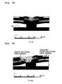
- FIGS. 6A, 6B are explanatory views showing a relationship among a polarization direction, portions (first active portions) which are effective while being turned ON and effective during application of voltage, and portions (second active portions) which are effective while being turned OFF and effective during non-application of voltage, regarding the first embodiment;
- Figs. 7A, 7B are explanatory views showing respectively volumetric changes of pressure chambers during non-application/application of voltage to first active portions;
- Fig. 8 is a view similar to Fig. 4 regarding a modification example of the first embodiment;
- Fig. 9 is a view similar to Fig. 4 regarding another modification example of the first embodiment;
- Fig. 10 is a view similar to Fig. 4 regarding a different modification example of the first embodiment;
- FIG. 11A, 11B are views similar to Figs. 6A, 6B respectively regarding the different modification example (see Fig. 10 ) of the first embodiment;
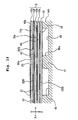
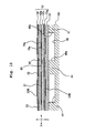
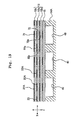
- Fig. 12 is a view similar to Fig. 4 regarding a further different modification example of the first embodiment;
- Figs. 13A, 13B are views similar to Figs. 6A, 6B respectively regarding the further different modification example of the first embodiment;
- Fig. 14 is a view similar to Fig. 4 regarding the second embodiment;
- Fig. 15 is a view similar to Fig. 4 regarding the third embodiment;
- Fig. 16 is a view similar to Fig. 4 regarding the forth embodiment;
- Fig. 17 is a view similar to Fig. 4 regarding the fifth embodiment;
- Figs. 18A, 18B are views similar to Figs.
- Fig. 19 is a view similar to Fig. 4 regarding the sixth embodiment
- Fig. 20 is a view.similar to Fig. 4 regarding the seventh embodiment
- Fig. 21 is a view similar to Fig. 5 regarding the seventh embodiment
- Figs. 22A, 22B are views similar to Figs. 6A, 6B respectively regarding the seventh embodiment
- Fig. 23 is a view similar to Fig. 4 regarding the eighth embodiment
- Fig. 24 is a view similar to Fig. 5 regarding the eighth embodiment
- Figs. 25A, 25B are views similar to Figs. 6A, 6B respectively regarding the eighth embodiment
- Figs. 26A, 26B are views similar to Figs.
- Figs. 27A, 27B are timing charts
- Fig. 28 is a view similar to Fig. 4 regarding the ninth embodiment
- Fig. 29 is a view similar to Fig. 5 regarding the ninth embodiment
- Figs. 30A, 30B are views similar to Figs. 6A, 6B respectively regarding the ninth embodiment
- Figs. 31A, 31B are views similar to Figs. 7A, 7B respectively regarding the ninth embodiment
- Fig. 32 is a view similar to Fig. 4 regarding the tenth embodiment
- Figs. 33A, 33B are views similar to Figs. 6A, 6B respectively regarding the tenth embodiment
- Figs. 34A, 34B are views similar to Figs.
- Fig. 35 is a view similar to Fig. 4 regarding the eleventh embodiment
- Fig. 36 is a view similar to Fig. 5 regarding the eleventh embodiment
- Figs. 37A, 37B are views similar to Figs. 6A, 6B respectively regarding the eleventh embodiment
- Figs. 38A, 38B are views similar to Figs. 7A, 7B respectively regarding the eleventh embodiment
- Fig. 39 is a schematic cross-sectional view regarding a conventional example
- Fig. 40 is an explanatory view showing a relationship among a polarization direction, portions which are effective during application of voltage, and portions which are effective during non-application of voltage regarding the conventional example
- Fig. 41 is an explanatory view showing volumetric changes of pressure chambers when applying voltage to active portions of the conventional example.
- Fig. 1A is a schematic structural view showing a schematic structure of an ink-jet printer (liquid-droplet jetting apparatus) according to the present invention
- Fig. 1B is an explanatory view showing a relationship among a cavity unit, a piezoelectric actuator and a flexible wiring board (COP) according to the present invention.
- COP flexible wiring board
- an ink-jet head 3 (liquid-droplet jetting head) for recording on a recording paper P (recording medium) is provided on a lower surface of a carriage 2 on which an ink cartridge (not shown) is mounted.
- the carriage 2 is supported by a carriage shaft 5 and a guide plate (not shown) provided in a printer frame 4, and reciprocates in a direction B orthogonal to a feeding direction A of the recording paper P.
- the recording paper P carried in the direction A from a not-shown paper feeding unit is introduced into a space between a platen roller (not shown) and the ink-jet head 3, where predetermined recording is performed with ink jetted toward the recording paper P from the ink-jet head 3, and is discharged thereafter by discharging rollers 6.
- the ink-jet head 3 is provided with a flexible wiring board 13 (signal line), which has a cavity unit 11 and a piezoelectric actuator 12 from a lower side in order, and supplies a drive signal to an upper surface of the piezoelectric actuator 12.
- a flexible wiring board 13 signal line
- the cavity unit 11 includes a stack 14 formed of a plurality of plate members.
- a top plate 15 is provided on an upper side of the stack 14.
- a plate assembly 18 is adhered integrally on a lower side of the stack 14, and the plate assembly 18 is formed by adhering a nozzle plate 16 having nozzle holes 16a and a spacer plate 17 having through holes 17a corresponding to the nozzle holes 16a.
- a piezoelectric actuator 12 for selectively jetting ink (liquid) in pressure chambers 40 is joined on an upper side of the top plate 15.
- a filter 19 for catching dust or the like included in the ink is provided on openings 11a of the cavity unit 11.
- the nozzle plate 16 is a plate of synthetic resin (polyimide resin for example) in which each of the nozzle holes 16a is provided to correspond to one of the pressure chambers 40 of the cavity plate 14A (forming the stack 14). Note that the nozzle plate 16 may be a metal plate.
- the stack 14 is formed such that a cavity plate 14A, a base plate 14B, an aperture plate 14C, two manifold plates 14D, 14E, and a damper plate 14F are stacked in this order from an upper side and these plates are bonded by a metal-diffusion bonding.
- These six plates 14A to 14F are aligned with each other and stacked so that ink channels are formed individually for the nozzle holes 16a, respectively.
- the cavity plate 14A is a metal plate in which openings functioning as a plurality of pressure chambers 40 are formed regularly corresponding to nozzle rows.
- the base plate 14B is a metal plate in which there are formed through holes 51a forming parts of communication holes 51 allowing communication between the pressure chambers 40 and manifolds 50 (common ink chambers) which will be explained later, and through holes 52a forming parts of communication holes 52 allowing communication between the pressure chambers 40 and the nozzle holes 16a.
- communication channels 21 allowing communication between the pressure chambers 40 and the manifolds 50 are formed as recessed channels.
- the aperture plate 14C is a metal plate in which there are provided communication holes 51b forming parts of the communication holes 51, and communication holes 52b forming parts of the communication holes 52.
- manifold plates 14D, 14E communication holes 50a, 50b defining the manifolds 50 are formed respectively. Furthermore, the manifold plates 14D, 14E are metal plates in which communication holes 52c, 52d forming parts of the communication holes 52 are provided respectively.
- the damper plate 14F is a metal plate in which communication holes 52e forming parts of the communication holes 52 are provided respectively, and damper chambers 53 which are formed as recesses also provided in a lower surface of the damper plate 14F.
- the cavity unit 11 includes the plurality of nozzle holes 16a, the plurality of pressure chambers 40 communicating with the nozzle holes 16a respectively and manifolds 50 temporarily storing ink supplied to the pressure chambers 40. Further, the communication holes 51a, 51b communicate with each other and form the communication holes 51 allowing communication between the pressure chambers 40 and the manifolds 50. Furthermore, the communication holes 52a to 52e communicate with each other and form the communication holes 52 allowing communication between the pressure chambers 40 and the nozzle holes 16a.
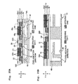
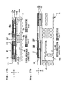
- the piezoelectric actuator 12 is formed by stacking a plurality of piezoelectric material layers 12a, 12b, 12c as shown in Fig. 4 .
- the piezoelectric material layers 12a to 12c are formed of lead zirconate titanate (PZT) based ceramic materials (piezoelectric sheets) having ferroelectricity, and is polarized in a thickness direction thereof (see Figs. 6A, 6B ).
- PZT lead zirconate titanate
- the piezoelectric actuator 12 includes, as viewed in a plan view (as viewed from a stacking direction of the cavity unit 11 and the piezoelectric actuator 12), first active portions 71, 72, 73 (first portions) corresponding to center portions of the pressure chambers 40 and second active portions 81, 82 (second portions) corresponding to left and right portions on outer peripheral sides which are more outside than the center portions of the pressure chambers 40.
- first active portions 71, 72, 73 correspond to piezoelectric sheets 12a, 12b, 12c respectively
- the second active portions 81, 82 correspond to left sides and right sides of the pressure chambers 40 respectively.
- the center portions of the pressure chambers 40 are center portions in a nozzle row direction X in which the nozzle holes 16a are arranged.
- the second active portions 81, 82 include not only regions corresponding to beam portions (girder portions, column portions) 41 which are walls partitioning adjacent pressure chambers 40 but regions corresponding to portions more inside (center portion side) than outer peripheral edges 40a of the pressure chambers 40.
- the first active portions 71 to 73 are, respectively, regions of the piezoelectric sheet 12a between individual electrodes 21A and first constant potential electrodes 22A, regions of the piezoelectric sheet 12b between the first constant potential electrodes 22A and individual electrodes 21B, and regions of the piezoelectric sheet 12c between the individual electrodes 21B and first constant potential electrodes 22B.
- both of the second active portions 81, 82 are regions of the piezoelectric sheets 12a to 12c between the individual electrodes 21A and the second constant potential electrodes 23.
- the electrodes 21A, 21B, 22A, 22B are formed of Ag-Pd based metal materials or the like.
- a driver IC 90 (see Fig. 1B ) supplying driving signals is electrically connected to the individual electrodes 21 via the flexible wiring board 13 (signal lines) .
- the driver IC 90 and the flexible wiring board 13 form a voltage application mechanism for applying driving voltage to the first and second active portions 71 to 73, 81, 82 of the piezoelectric actuator 12.
- a first potential (ground potential) and a second potential different therefrom (20 V for example) are applied selectively to the individual electrodes 21 via the flexible wiring board 13 to change volumes of the pressure chambers 40. Further, the first potential (ground potential) is applied constantly to the first constant potential electrodes 22A, 22B, and the second potential (20 V for example) is applied constantly to the second constant potential electrodes 23.
- the piezoelectric actuator 12 has the individual electrodes 21 corresponding to the pressure chambers 40.
- the piezoelectric actuator 12 changes the volumes of the pressure chambers 40 to jet ink from the nozzle holes 16a, when the first potential (ground potential) and the second potential (positive potential) are applied selectively to the individual electrodes 21 as drive signals.
- a length of the individual electrodes 21 is shorter than a length of the pressure chambers 40 in a direction Y orthogonal to the nozzle row direction X (see Fig. 6B ), but longer than a length of the pressure chambers 40 in the nozzle row direction X.
- the individual electrodes 21 are formed to range across regions (first region) corresponding to the first active portions 71 to 73 and regions (second region) corresponding to the second active portions 81, 82 so as to cover both of these regions.
- a length of the first constant potential electrodes 22A, 22B is shorter than a length of the pressure chambers 40 in the nozzle row direction X so as to cover regions corresponding to the first active portions 71 to 73.
- a length of the first constant potential electrodes 22B located on the side of the pressure chambers 40 is longer in the nozzle row direction X than a length of the first constant potential electrodes 22A located away from the pressure chambers 40. That is, the individual electrodes 21 are shared (used commonly) for the first and second constant potential electrodes 22A, 22B, 23.
- the second constant potential electrodes 23 are formed to cover regions corresponding to the second active portions 81, 82 and regions corresponding to the beam potions 41 between the pressure chambers 40 which are adjacent to each other in a direction orthogonal to the nozzle row direction. That is, the second constant potential electrodes 23 extend to regions corresponding to side portions, of the pressure chambers 40, in the nozzle row direction, the side portions including the beam portions 41. Each of the second constant potential electrodes is shared for two pressure chambers 40 which are adjacent to each other in the nozzle row direction.
- the individual electrodes 21 are formed on a side of one surface (upper face in Fig. 4 ) of the piezoelectric material layer 12a which is farthest from the pressure chambers 40, and the first constant potential electrodes 22A and the second constant potential electrodes 23 are formed on a side of the other surface (lower face in Fig. 4 ) of the piezoelectric material layer 12a. Accordingly, the first active portions 71 and the second active portions 81 are formed side by side in the same piezoelectric material layer 12a. Further, the first constant potential electrodes 22A and the second constant potential electrodes 23 are formed alternately on a side of one surface (upper face in Fig.
- the individual electrodes 21 are formed on a side of the other surface (lower face in Fig. 4 ) of the piezoelectric material layer 12b.
- the first active portions 72 and the second active portions 82 corresponding to the first active portions 71 and the second active portions 81 of the piezoelectric material layer 12a, are formed side by side in the same piezoelectric material layer 12b.
- the individual electrodes 21 are formed on a side of one surface (upper face in Fig. 4 ) of the piezoelectric material layer 12c which is closest to the pressure chambers 40, and the first constant potential electrodes 22B are formed on a side of the other surface (lower face in Fig.
- the first active portions 73 are formed in the piezoelectric material layer 12c.
- a length of the first active portions 73 is longer than a length of the first active portions 71, 72 in the nozzle row direction, since the constant potential electrodes 22B are longer than the constant potential electrodes 22A in the nozzle row direction X.
- the electrodes 21, 22A, 22B, 23 of the respective piezoelectric sheets 12a to 12c are arranged in a plan view as shown in Fig. 5 .
- the individual electrodes 21 are arranged at a constant pitch in the nozzle row direction (X direction) corresponding respectively to the pressure chambers 40.
- a plurality of rows of individual electrodes 21 are arranged in the Y direction.
- the individual electrodes 21 are formed to be shifted by a half pitch from each other in the X direction.
- connection portions 26 to be connected to the connection terminals (not shown) of the flexible wiring board 13 are formed in a zigzag pattern.
- the first constant potential electrodes 22A are formed at a constant pitch in the nozzle row direction corresponding respectively to the pressure chambers 40.
- One ends of the first constant potential electrodes 22A are connected to one of first common electrodes 27A which is kept at the ground potential and extends in the nozzle row direction.
- the second constant potential electrodes 23 are formed respectively, and one ends thereof are also at positive potential (for example 20 V: constant) and connected to one of second common electrodes 28 extending in the nozzle row direction X.
- middle electrodes 25 are formed in a zigzag form (see Fig.
- the first constant potential electrodes 22B are formed at a constant pitch in the nozzle row direction corresponding respectively to the pressure chambers 40, and one ends thereof are connected to one of first common electrodes 27B at the ground potential extending in the nozzle row direction X. Note that the first constant potential electrodes 22B located on the side of the pressure chambers 40 are formed longer in length in the nozzle row direction X than the first constant potential electrodes 22A located away from the pressure chambers 40.
- the first active portions 71 to 73 are polarized in the same direction (polarization direction) as the direction of the electric field generated by the applied voltage when the second potential is applied to the individual electrodes 21 and the first potential is applied to the first constant potential electrodes 22A, 22B for deformation.
- the second active portions 81, 82 are polarized in the same direction as the direction of the electric field generated by the applied voltage when the first potential is applied to the individual electrodes 21 and the second potential is applied to the second constant potential electrodes 23 for deformation. That is, the directions of the electric field generated by the applied voltage and the polarization directions are the same.
- portions which are "effective while being turned ON” correspond respectively to the first active portions to which voltage (20 V) is applied when the second potential is applied to the individual electrodes 21, and portions which are "effective while being turned OFF” correspond respectively to the second active portions to which voltage (20 V) is applied when the first potential is applied to the individual electrodes 21.
- the first constant potential electrodes 22A, 22B are always at the first potential (ground potential), and the second constant potential electrodes 23 are always at the second potential (positive potential). Then, the first potential (ground potential) and the second potential (positive potential) are applied to the individual electrodes 21 selectively for changing the volumes of the pressure chambers 40. That is, as shown in Table 1 below, the direction of the electric field generated by the applied voltage is the same during polarization and during driving. However, the first constant potential electrodes 22A, 22B are always at the ground potential (0 V), the second constant potential electrodes 23 are always at the positive potential (20 V: constant), and to the individual electrodes 21, the positive potential (20 V: constant) is applied or this application is released (see Fig. 27A ).
- the voltage applied between electrodes during driving is, as shown in Table 1, smaller than the voltage applied during polarization, thereby suppressing deterioration due to repeated application of voltage between electrodes.
- the electrodes 21, 22A, 22B, 23 are arranged as described above, during non-application of voltage to the first active portions 71 to 73 (during standby) in which the second potential (ground potential) is applied to the individual electrodes 21 by the voltage application mechanism, the first active portions 71 to 73 are in a state of non-expand/non-contract (non-deform) in the first and second directions Z, X.
- the second active portions 81, 82 are in a voltage applied state, and attempt to expand in a stacking direction Z (first direction) toward the pressure chambers 40 and contract in the nozzle row direction X (second direction) orthogonal to the stacking direction Z.
- the second active portions 81, 82 located at the side portions in the nozzle row directions deform to bend in a direction to depart from the pressure chambers 40.
- this deformation of the second active portions 81, 82 contributes to increasing of volumetric changes of the pressure chambers 40, and contributes to sucking of a large amount of ink from the manifolds 50 to the pressure chambers 40.
- the first active portions 71 to 73 during application of voltage (during driving) to the first active portions 71 to 73 in which the first potential (positive potential: 20 V) is applied to the individual electrodes 21, the first active portions 71 to 73, being applied with voltage in the same direction as the polarization direction, expand in the stacking direction Z toward the pressure chambers 40 and contract in the nozzle row direction X orthogonal to the stacking direction Z thereof by piezoelectric lateral effect. Accordingly, the first active portions 71 to 73 turn to a state of projecting and deforming in a direction toward insides of the pressure chambers 40.
- the top plate 15 does not contract spontaneously because it is not influenced by electric field, a difference is made in distortion in the polarization direction and in the vertical direction between the piezoelectric material layer 12c located on the upper side and the top plate 15 located on the lower side.
- This and the top plate 15 being fixed to the cavity plate 14A together cause the piezoelectric material layer 12c and the top plate 15 to attempt to deform so as to project toward the side of the pressure chambers 40 (unimorph deformation). Accordingly, the volumes of the pressure chambers 40 decrease, the pressure of ink increases, and the ink is jetted from the nozzle holes 16a.
- the second active portions 81, 82 turn to a non application state of voltage, and hence return to a state of non-expand/non-contract (non-deform) in the first and second directions Z, X.
- the second active portions 81, 82 return to a state of not deforming. Therefore, as shown in Fig. 7B , the influence of deformation of the first active portions 71 to 73 is cancelled by the second active portions 81, 82 and hardly reaches the pressure chambers 40 adjacent thereto, thereby suppressing crosstalk.
- the first active portions 71 to 73 turn to a state of not deforming as described above.
- the second active portions 81, 82 deform to bend in a direction to depart from the pressure chambers 40, and the volumes of the pressure chambers 40 return to the original volumes.
- the ink is sucked into the pressure chambers from the manifolds 50.
- the jetting operation of ink is repeated by such deformation of the first active portions 71 to 73 and the second active portions 81, 82, and volumetric changes of the pressure chambers 40 are made to be large in each jetting operation, thereby increasing jetting efficiency and suppressing crosstalk in the three directions.
- the ratio of changes of cross-sectional areas of adjacent pressure chambers were obtained in the first embodiment and the conventional example (see Fig. 40 ). As shown in Table 2, it is 11% in the case of the first embodiment while it is 24% in the case of the conventional example. The change ratio in the case of the first embodiment decreases to almost half as compared to the conventional example, and it can be seen that the effect of suppressing crosstalk is exhibited.
- the second active portions 81, 82 are arranged across the first regions and the second regions, the first regions corresponding to the portions on the outer peripheral sides which are more outside than the center portions of the pressure chambers 40 in the nozzle row direction X, and the second regions corresponding to the beam portions 41.
- the second constant potential electrodes 23A are provided only in the regions corresponding to the beam portions 41 irrelevantly to the regions corresponding to the pressure chambers 40, and second active portions 81a, 82a exist only in the regions corresponding to the beam portions 41.
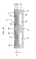
- second active portions 81b, 82b exist only in the regions corresponding to portions on the outer peripheral sides of the pressure chambers 40. That is, the second constant potential electrodes 23B can be provided only in the regions corresponding to the portions on the outer peripheral sides which are more outside than the center portions of the pressure chambers 40 irrelevantly to the regions corresponding to the beam portions 41.
- lengths of the second active portions 81b, 82b in the nozzle row direction become shorter, as compared to the structure in which the above-described second active portions 81, 82 are arranged across the first regions and the second regions, the first regions corresponding to the portions on the outer peripheral sides which are more outside than the center portions of the pressure chambers 40, and the second regions corresponding to the beam portions 41 (see Fig. 4 ). Therefore, although being lower in effect of suppressing crosstalk and effect of contributing to volumetric changes, the point that these effects are exhibited is the same as described above.
- a piezoelectric material layer 12d is provided, without providing the top plate, on the upper side of the cavity plate 14A via an insulating layer 12e having a small layer thickness, and first and second active portions are formed in this piezoelectric material layer 12d.
- the first and second constant potential electrodes 22A, 23 are formed alternately on one surface (upper surface), and the individual electrodes 21 are formed on the other surface (lower surface). Accordingly, there are formed first active portions 71, 72, 73a, 74 corresponding respectively to the center portions of the pressure chambers 40, and second active portions 81, 82, 83, 84 corresponding respectively to portions on outer peripheral sides thereof.
- first active portions portions which are effective while being turned ON and effective during application of voltage
- second active portions portions which are effective while being turned OFF and effective during non-application of voltage
- the first active portions 71, 72, 73a, 74 and the second active portions 81, 82, 83, 84 both perform deformation of vertical effect, not the uniform deformation, and hence the second active portions 81 to 84 cannot deform to bend away from the pressure chambers 40 like the uniform deformation (that is, deformation in a direction to enlarge the pressure chambers 40). Therefore, the effect of suppressing crosstalk can be obtained, but the effect of increasing volumetric changes of the pressure chambers 40 cannot be obtained.
- the second constant potential electrodes 23A are provided only in the regions corresponding to the beam portions 41 (see Fig. 8 ), similarly it can also be a structure as a matter of course in which the piezoelectric material layer 12d is provided on the side of the pressure chambers 40 via the insulating layer 12e having a small layer thickness.
- the first and second constant potential electrodes 22A, 23A are arranged alternately on one surface (upper surface), and the individual electrodes 21 are arranged on the other surface (lower surface). Accordingly, there are formed first active portions 71, 72, 73a, 74 corresponding respectively to the center portions of the pressure chambers 40, and second active portions 81, 82, 83, 84 corresponding respectively to portions on outer peripheral sides thereof.
- first active portions portions which are effective while being turned ON and effective during application of voltage
- second active portions portions which are effective while being turned OFF and effective during non-application of voltage
- the first and second constant potential electrodes 22A, 23 when forming the first and second constant potential electrodes 22A, 23 on the same surface alternately in the nozzle row direction X, it is not possible to take large intervals between these electrodes, and hence the lengths of these electrodes in the nozzle row direction cannot be taken long.
- an insulating layer with a small layer thickness can be used to increase the lengths of them.
- the piezoelectric actuator has a stacked structure in which an insulating layer 12f having a smaller layer thickness than the piezoelectric material layers 12a, 12b is sandwiched between the piezoelectric material layer 12a and the piezoelectric material layer 12b.
- this insulating layer 12f can be formed of the same material as the piezoelectric material layers 12a to 12d.
- first constant potential electrodes 22B are formed on one surface (upper surface) side of this insulating layer 12f at a constant pitch, and only second constant potential electrodes 23 are formed on the other surface (lower surface) side thereof at a constant pitch. Accordingly, the first constant potential electrodes 22B and the second constant potential electrodes 23 are electrically isolated with the insulating layer 12f, but similarly to the case of the first embodiment, they are formed between the piezoelectric material layer 12a and the piezoelectricmaterial layer 12b. Thus, there are formed first active portions 71a, 72a, 73 corresponding respectively to the center portions of the pressure chambers 40, and second active portions 81c, 82 corresponding respectively to portions on outer peripheral sides thereof.
- the lengths in the nozzle row direction of the first constant potential electrodes 22B formed between the piezoelectric material layer 12a and the piezoelectric material layer 12b can be made long, thereby realizing an electrode arrangement which is advantageous for increasing volumetric changes of the pressure chambers 40.
- the ratio of changes of cross-sectional areas of adjacent pressure chambers is 11%.
- the change ratio decreases to almost half as compared to the case of the conventional example, and it can be seen that the effect of suppressing crosstalk is exhibited.
- the uppermost piezoelectric material layer 12a in the second embodiment is omitted, and instead, another insulating layer 12g with a small layer thickness similar to the insulating layer 12f is arranged between the piezoelectric material layer 12c and the top plate 15.
- Second constant potential electrodes 23 are formed on an upper surface side of the insulating layer 12g, and first constant potential electrodes 22B are formed on a lower surface side thereof.
- the first and second constant potential electrodes 22B, 23 are formed symmetrically sandwiching the individual electrodes 21 arranged on the lower surface side of the piezoelectric material layer 12b. Accordingly, there are formed first active portions 72a, 73a corresponding respectively to the center portions of the pressure chambers 40, and second active portions 82,83 corresponding respectively to portions on outer peripheral sides thereof.
- only one layer may exist as the piezoelectric material layers described above, and it can also be a structure as described in the next forth embodiment.
- first and second constant potential electrodes 22B, 23 are formed alternately in the nozzle row direction on the other surface (lower surface) side. Accordingly, there are formed first active portions 71a corresponding respectively to the center portions of the pressure chambers 40, and second active portions 81, 81 corresponding respectively to both sides of portions on outer peripheral sides thereof.
- the top plate 15 functions as a binding plate.
- the number of piezoelectric material layers is smaller than in the first to third embodiments and the amount of deformation becomes smaller, excellent jetting efficiency can be realized by unimorph deformation even with one piezoelectric material layer 12a.
- Individual electrodes 21 are formed on an upper surface side of the piezoelectric material layer 12a, and second constant potential electrodes 23 are formed on a lower surface side thereof.
- first constant potential electrodes 22B are formed on a lower surface side of the insulating layer 12h. Accordingly there are formed first active portions 71b corresponding respectively to the center portions of the pressure chambers 40, and second active portions 81 corresponding respectively to portions on outer peripheral sides thereof.
- the second active portions can be provided only on one sides of the first active portions, as described in sixth embodiment.
- individual electrodes 21A are arranged in parts of regions corresponding to the pressure chambers 40 and regions corresponding to the beam portions 41.
- first and second constant potential electrodes 22A, 23A are formed corresponding respectively to side portions of the individual electrodes 21A on the other surface (lower surface) side thereof.
- individual electrodes 21A are formed on an upper surface side of the piezoelectric material layer 12c, and first constant potential electrodes 22A are formed on a lower surface side thereof. Accordingly, there are formed first active portions 71, 72, 73a corresponding respectively to the center portions of the pressure chambers 40, and second active portions 81c, 82c corresponding respectively to portions of outer peripheral sides thereof.
- first constant potential electrodes extending along the nozzle row direction, and to have them in common for the pressure chambers formed in rows in the nozzle row direction.
- Fig. 20 there are provided four piezoelectric material layers 12a to 12d.
- Individual electrodes 21 are formed on one surface (upper surface) side of the piezoelectric material layer 12a farthest from the pressure chambers 40, and second constant potential electrodes 23 are formed on the other surface (lower surface) side thereof.
- first constant potential electrodes 22C are formed on one surface side of a piezoelectric material layer 12c that is third one from the piezoelectric material layer 12a toward the pressure chambers 40, and individual electrodes 21B are formed on the other surface side thereof.
- first constant potential electrodes 22C are formed on a side of the pressure chambers 40 of a piezoelectric material layer 12d that is fourth one from the piezoelectric material layer 12a toward the pressure chambers 40. Accordingly, there are formed first active portions 171, 73, 74 corresponding respectively to the center portions of the pressure chambers 40, and second active portions 181 corresponding respectively to portions on outer peripheral sides thereof.
- the electrodes 21, 22B, 22C, 23 of the respective piezoelectric material layers 12a to 12d are arranged as shown in Fig. 21 in a plan view. Namely, on an upper surface side (first layer) of the piezoelectric material layer 12a and a lower surface side (third layer) of the piezoelectric material layer 12c, individual electrodes 21, 21B are formed at a constant pitch in the nozzle row direction X corresponding respectively to the pressure chambers 40. Then the adjacent individual electrodes 21, 21B are formed to be shifted by a half pitch in the nozzle row direction. Between these rows, connection terminals 26, 26B of the individual electrodes 21, 21B are formed in a zigzag pattern.
- connection terminals (not shown) of the flexible wiring board 13 are connected to connection terminal portions 26 of the individual electrodes 21.
- These connection terminal portions 26 of the individual electrodes 21 are connected electrically to the connection terminal portions 26B of the respective individual electrodes 21B via through holes 24 (filled with conductive materials inside) penetrating the piezoelectric material layers 12a to 12c and via middle electrodes 25 formed on a lower surface side of the piezoelectric material layer 12a and an upper surface side of the piezoelectric material layer 12c (see Fig. 22B ).
- the individual electrodes 21 on the upper surface side of the piezoelectric material layer 12a are formed longer than the individual electrodes 21B on the lower surface side of the piezoelectric material layer 12c in length in the nozzle row direction.
- second constant potential electrodes 23 are formed at a constant pitch in the nozzle row direction corresponding to the pressure chambers 40, and one ends thereof are connected to one of common electrodes 28 extending in the nozzle row direction.
- first constant potential electrodes 22C are formed to extend in the nozzle row direction corresponding respectively to the pressure chambers 40.
- first constant potential electrodes 22C are formed in the nozzle row direction X and are shared by the pressure chambers 40 in the nozzle row direction, the arrangement of the electrodes 21, 21B, 22C, 23 becomes simple, which is advantageous for making the apparatus compact.
- first active portions portions which are effective while being turned ON and effective during application of voltage
- second active portions portions which are effective while being turned OFF and effective during non-application of voltage
- connection portions to the flexible wiring board 13 are arranged on the piezoelectric material layer 12a which is farthest from the pressure chambers, there is a fear that during connection with solder, dispersion of deformation characteristics due to flowing in of the solder occurs. Accordingly, as in the next eighth embodiment, such a problem can be avoided by arranging the individual electrodes between the piezoelectric material layer 12a and the piezoelectric material layer 12b located more inside, similarly to the case of the third embodiment.
- surface individual electrodes for connection are formed on one surface (farthest surface) side of the piezoelectric material layer (farthest layer) which is farthest from the pressure chambers, and individual electrodes are formed on the other surface side thereof.
- first constant potential electrodes 22D are formed on a surface on the side of the pressure chambers 40 of the piezoelectric material layer 12c which is closest to the pressure chambers 40.
- second constant potential electrodes 23A are formed on a farthest surface 31, which is a surface on a side opposite to the pressure chambers 40, of the piezoelectric material layer 12a located farthest from the pressure chambers 40 of the plurality of piezoelectric material layers 12a to 12c.
- the individual electrodes 21 are formed on a surface on the side of the pressure chambers 40 of the piezoelectric material layer 12a. That is, they are formed on a surface, which is a surface different from the farthest surface 31, of one of the piezoelectric material layers 12a to 12c and is a surface on the side of the pressure chambers 40 of the piezoelectric material layer 12a (farthest layer). Then the surface individual electrodes 29 to be input terminals to the individual electrodes 21 are formed in regions (regions corresponding to the beam portions 41) more outside than outer peripheral edges of the pressure chambers 40 of the farthest surface 31.
- These surface individual electrodes 29 and the individual electrodes 21 conduct to each other via the conductive materials 24 filled in the through holes penetrating the piezoelectric material layer 12a.
- the surface individual electrodes 29 are formed in regions of the farthest surface 31 between the adjacent pressure chambers 40 (regions corresponding to the so-called beam portions 41).
- first active portions 71, 72 corresponding respectively to the center portions of the pressure chambers 40
- second active portions 182 corresponding respectively to portions on outer peripheral sides thereof. Therefore, the second active portions 182 are formed in the piezoelectric material layers 12b, 12c on the side of the pressure chambers 40, which are layers other than the farthest layer (piezoelectric material layer 12a) of the plurality of piezoelectric material layers 12a to 12c.
- the electrodes 21, 22D, 23A formed on the surfaces of the piezoelectric material layers 12a to 12c are arranged as shown in Fig. 24 , in a plan view.
- the second constant potential electrodes 23A are formed at a constant pitch in the nozzle row direction corresponding respectively to the pressure chambers 40, and the adjacent second constant potential electrodes 23A are formed to be shifted by a half pitch in the nozzle row direction.
- the surface individual electrodes 29 are formed corresponding respectively to the individual electrodes 21 between the second constant potential electrodes 23A in the nozzle row direction on the upper surface side of the piezoelectric material layer 12a. End portions of the surface individual electrodes 29 on sides opposite to the second constant potential electrodes 23A are formed in a zigzag pattern as connection terminal portions 26B which extend to portions between the adjacent pressure chambers 40 to be connected to the connection terminals of the flexible wiring board 13.
- the individual electrodes 21 are formed at a constant pitch in the nozzle row direction corresponding respectively to the pressure chambers 40, and connection terminal portions 26 thereof are connected respectively to the connection terminals 26B of the surface individual electrodes 29 using the conductive materials filled in the through holes 24 penetrating the piezoelectric material layer 12a (see Fig. 25A ).
- the first constant potential electrodes 22D which are in common to two adjacent rows of pressure chambers 40 are formed so as to extend in the nozzle row direction.
- connection terminal portions 26B to which the connection terminals of the flexible wiring board 13 are connected are formed in the regions corresponding to the beam portions 41 which do not deform while driving, dispersion of deformation characteristics for the respective first active portions does not easily occur if solder flows in during connection with the connection terminals of the flexible wiring board 13.
- jetting occurs when voltage is applied to the first active portions (that is, when the second potential is applied to the individual electrodes) as shown in Fig. 27A , but in the case of the eighth embodiment and the tenth embodiment which will be explained later, as shown in Fig. 27B , conversely jetting occurs when application of voltage to the first active portions is released (that is, when the first potential is applied to the individual electrodes).
- the piezoelectric actuator is made as a two-layer structure, in which second constant potential electrodes 23C are formed on an upper surface side of the piezoelectric material layer 12a on an upper side, and individual electrodes 21 are formed on a lower surface side thereof. Then first constant potential electrodes 22C are formed on a lower surface side of the piezoelectric material layer 12b on a lower side. Accordingly, there are formed first active portions 72 corresponding respectively to the center portions of the pressure chambers 40, and the second active portions 81 corresponding respectively to portions on outer peripheral sides thereof.
- individual surface electrodes 21c to be connection portions with the flexible wiring board 13 are formed in regions corresponding to the beam portions 41 between the pressure chambers 40 as shown in Fig. 29 .
- a time to apply voltage between the second constant potential electrodes 23C and the individual electrodes 21 is short, and hence short-circuit by migration is avoided.
- the electrodes on upper and lower surfaces of the piezoelectric material layers 12a, 12b are arranged as shown in Fig. 29 in a plan view. That is, on the upper surface side of the piezoelectric material layer 12a, the second constant potential electrodes 23C are formed corresponding respectively to the pressure chambers 40 at a constant pitch in the nozzle row direction, and both side portions thereof in a direction orthogonal to the nozzle row direction are connected by common electrodes 28A, 28B respectively.
- the adjacent second constant potential electrodes 23C are formed to be shifted by a half pitch in the nozzle row direction, and surface individual electrodes 29A to be connected to the connection terminals of the flexible wiring board 13 are formed between the adjacent common electrodes 28A, 28B on a side opposite to the side on which the second constant potential electrodes 23C are formed.
- individual electrodes 21 are formed at a constant pitch in the nozzle row direction corresponding respectively to the pressure chambers 40. Parts of the individual electrodes 21 are formed to project to be connection terminal portions 26, and are connected electrically to the surface individual electrodes 29A on the upper surface of the piezoelectric material layer 12a via through holes 24 filled with conductive materials inside.
- first constant potential electrodes 22C are formed at a constant pitch in the nozzle row direction corresponding respectively to the pressure chambers 40, and end portions thereof are connected to the adjacent first constant potential electrodes 22C mutually via connection portions 27C.
- Figs. 30A, 30B a relationship among the polarization direction, portions (first active portions) which are effective while being turned ON and effective during application of voltage and portions (second active portions) which are effective while being turned OFF and effective during non-application of voltage is shown in Figs. 30A, 30B . Then it can be seen that the effect of suppressing crosstalk is exhibited by application/non-application of voltage as shown in Figs. 31A, 31B .
- first constant potential electrodes 22D are formed on an upper surface side of the piezoelectric material layer 12a, and individual electrodes 21 are formed on a lower surface side thereof. Further, second constant potential electrodes 23D are formed on an upper surface side of the piezoelectric material layer 12c, and first constant potential electrodes 22E are formed on a lower surface side thereof.
- the individual electrodes 21 are connected respectively to the surface individual electrodes 29A using through holes 24 (filled with conductive materials inside) penetrating the piezoelectric material layer 12a (see Fig. 33B ). Accordingly, there are formed second active portions 82 corresponding respectively to the center portions of the pressure chambers 40, and first active portions 71, 172 on portions on outer peripheral sides thereof respectively.
- individual electrodes 21 are formed on an upper surface side of the piezoelectric material layer 12a, and second constant potential electrodes 23E are formed on a lower surface side thereof.
- First constant potential electrodes 22F are formed on a lower surface side of the piezoelectric material layer 12b. Accordingly, there are formed first active portions 81 corresponding respectively to the center portions of the pressure chambers 40, and second active portions 171 on portions on outer peripheral sides thereof. Note that it is the same as the eighth and tenth embodiments in that the ground potential is applied to the individual electrodes 21 during standby.
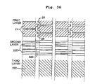
- the electrodes on the upper and lower surfaces of the piezoelectric material layers 12a, 12b are arranged as shown in Fig. 36 in a plan view. That is, on the upper surface side of the piezoelectric material layer 12a, the individual electrodes 21 are formed corresponding respectively to the pressure chambers 40 at a constant pitch in the nozzle row direction, and parts of the individual electrodes project between the arrays of the individual electrodes 21. These projecting portions are formed in a zigzag pattern to be connection terminal portions 26 connected to the connection terminals of the flexible wiring board 13.
- the second constant potential electrodes 23E are formed at a constant pitch in the nozzle row direction corresponding respectively to the pressure chambers 40, and one ends thereof are connected electrically to one of common electrodes 23Ea located therebetween. Further, on the lower surface side of the piezoelectric material layer 12b, there are formed first constant potential electrodes 22E extending in the nozzle row direction to be electrodes common to the pressure chambers 40 in the nozzle row direction.
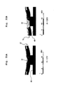
- a relationship among the polarization direction, portions (first active portions) which are effective while being turned ON and effective during application of voltage and portions (second active portions) which are effective while being turned OFF and effective during non-application of voltage is as shown in Figs. 37A, 37B .
- the effect of suppressing crosstalk is exhibited by application/non-application of voltage as shown in Figs. 38A, 38B .
- the ratio of changes of cross-sectional areas of adjacent pressure chambers is 3%, and the change ratio decreases significantly as compared to the conventional example. It can be seen that it has excellent effect of suppressing crosstalk.
- liquid-droplet jetting apparatus is an ink-jet type recording apparatus, but the present invention is not limited to this. It may also be applied to another liquid-droplet jetting apparatus for applying a colored liquid with micro liquid-droplets, for forming a wiring pattern by jetting electrically conductive liquid, or the like.
- the recording medium not only the recording paper but various kinds of materials such as resin, cloth, and the like can be applied, and as the liquid to be jetted, not only the ink but various kinds of liquids such as colored liquid, functional liquid, and the like can be applied.
Landscapes
- Particle Formation And Scattering Control In Inkjet Printers (AREA)
Abstract
Description
- This application claims priority from Japanese Patent Application No.
2007-256922, filed on September 29, 2007 - The present invention relates to a liquid-droplet jetting apparatus such as an ink-jet printer and a liquid-droplet jetting head such as an ink-jet head.
- Conventionally, as one of liquid-droplet jetting apparatuses, there is known an ink-jet printer provided with an ink-jet head having a cavity unit in which a plurality of pressure chambers are formed regularly and a piezoelectric actuator joined to the cavity unit for selectively jetting ink in the pressure chambers, and a voltage application mechanism for applying a voltage to the piezoelectric actuator. Then, as the piezoelectric actuator described above, there are known one using a vertical effect actuator of stacked type (see, for example, Japanese Patent Application Laid-open No.
2005-59551 2005-317952 - There are demands for increasing the density of the pressure chambers to secure high image quality or high quality of recording by increasing the number of nozzles in the ink-jet head of such an ink-jet printer. When the pressure chambers are arranged with high density, the distance between adjacent pressure chambers becomes short, and thus the influence to adjacent pressure chambers, a problem of so-called crosstalk occurs while driving.
- Specifically, as shown in
Figs. 39 ,40 for example, the ink-jet head is formed such that apiezoelectric actuator 912 formed of threepiezoelectric material layers cavity unit 914, in whichpressure chambers 940 are formed regularly, via abinding plate 915. Thenindividual electrodes 921 corresponding to thepressure chambers 940 are provided on a side of an upper surface of thepiezoelectric material layer 912a, and constant potential electrodes 922 (ground potential) are provided on a side of a lower surface of thepiezoelectric material layer 912a. Further,individual electrodes 921 and constantpotential electrodes 922 are provided on an upper surface side and a lower surface side of thepiezoelectric material layer 912c, respectively. With such a structure, regions (piezoelectric material layers) sandwiched between theindividual electrodes 921 and the constantpotential electrodes 922 function as active portions S where volumes of thepressure chambers 940 are changed by applying positive potential selectively to theindividual electrodes 921 so as to jet ink fromnozzle holes 914b. Such deformation for jetting ink affects not only the pressure chambers jetting ink but also thepressure chambers 940 adjacent to thesepressure chambers 940 by deformation of thepiezoelectric material layers 912a to 912c, as shown inFig. 41 . - Accordingly, there has been occurring a problem of fluctuation of jetting characteristics for the adjacent pressure chambers 940 (for example, a problem that unintended jetting of ink occurs from the
nozzle holes 914b), namely, a problem of crosstalk. - To solve such a problem of crosstalk, various measures have been proposed. For example, in Japanese Patent Application Laid-open No.
2002-254640 Fig. 2 ), there is described a structure in which a beam portion 100 is provided acrosspartition walls 11 on both sides in a width direction of eachpressure generating chamber 12 so as to improve the rigidity of thepartition walls 11, and thereby occurrence of crosstalk is prevented between adjacent pressure generating chambers. - Further, in Japanese Patent Application Laid-open No.
2002-19113 Fig. 1 ), there is described a structure in which an elastic body 7 having a predetermined depth from anozzle plate 3 and a predetermined width is disposed on aside wall 5 that separates each pressurizing liquid chamber 4, thereby decreasing mechanical crosstalk. - However, these measures are becoming no longer perfect as the increase in density of the pressure chambers (ink jetting ch) proceeds.
- An object of the present invention is to provide a liquid-droplet jetting apparatus and a liquid-droplet jetting head capable of suppressing crosstalk without increasing the number of individual electrodes, namely, the number of signal lines when structured with high density.
- According to a first aspect of the present invention, there is provided a liquid-droplet jetting apparatus which jets droplets of a liquid, including:
- a liquid-droplet jetting head including a cavity unit in which a plurality of pressure chambers arranged regularly are formed and a piezoelectric actuator which is joined to the cavity unit to cover the pressure chambers and which jets the liquid in the pressure chambers selectively, the piezoelectric actuator having first active portions each corresponding to a center portion of one of the pressure chambers and second active portions each corresponding to an outer peripheral portion, of one of the pressure chambers, which covers a portion located outside of the center portion of one of the pressure chambers; and
- a voltage application mechanism which applies a voltage to the piezoelectric actuator;
- Here, the "active portions" means portions which turn to a deformation state or a non-deformation state by application/non-application of voltage. Further, the "second active portions" include, besides the case of existing across portions corresponding to pressure chambers and portions corresponding to beam portions between the pressure chambers, the case of existing only in the portions corresponding to beam portions out of the portions corresponding to the pressure chambers and the case of existing only in the portions corresponding to the pressure chambers. The "first direction" means a direction in which the pressure chambers and the active portions are aligned, that is, a stacking direction of the piezoelectric actuator and the cavity unit.
- In this manner, according to application/non-application of voltage, deformation occurs in reverse directions in the first active portions corresponding to the center portions of the pressure chambers and the second active portions corresponding to the portions on the outer peripheral sides which are more outside than the center portions of the pressure chambers. When the pressure chambers are arranged with high density and hence adjacent pressure chambers are close to each other, deformation of the first active portions is cancelled, when being transmitted to adjacent pressure chambers, by deformation of the second active portions, thereby suppressing so-called crosstalk which is propagation of deformation of the first active portions to adjacent pressure chambers. The first voltage applied to the first active portions may be same as the second voltage applied to the second active portions.
- In the liquid-droplet jetting apparatus of the present invention, each of the second active portions may cover an inside portion located inside an outer peripheral edge of one of the pressure chambers.
- In this case, not only the first active portions but the second active portions contribute to volumetric changes of the pressure chambers, and thus volumes of the pressure chambers can be changed larger than in the case only by the first active portions. Therefore, it is possible to improve jetting efficiency (jetting amount when voltage is applied) for jetting liquids in the pressure chambers selectively by applying the voltage to the piezoelectric actuator.
- In the liquid-droplet jetting apparatus of the present invention, the piezoelectric actuator may include individual electrodes to which first potential and second potential different from the first potential are applied selectively, first constant potential electrodes to which the first potential is applied, and second constant potential electrodes to which the second potential is applied; each of the first active portions may include a piezoelectric material sandwiched between one of the individual electrodes and one of the first constant potential electrodes; and each of the second active portions may include a piezoelectric material sandwiched between one of the individual electrodes and one of the second constant potential electrodes.
- In this case, just by applying the first potential and the second potential selectively to the individual electrodes, deformation of the first active portions and deformation of the second active portions (returning to an original state) can be made to occur at the same time completely. Thus, an attempt of the deformation of the first active portions to propagate to adjacent pressure chambers is cancelled by the deformation of the second active portions, thereby suppressing crosstalk without requiring highly precise timing control.
- In the liquid-droplet jetting apparatus of the present invention, the individual electrodes may be formed across a first region corresponding to the first active portions and a second region corresponding to the second active portions of the piezoelectric actuator so as to cover the first and second regions; the first constant potential electrodes may be formed to cover the first region of the piezoelectric actuator; and the second constant potential electrodes may be formed to cover the second region of the piezoelectric actuator.
- In this case, the electrodes can be arranged efficiently, and thereby arrangement without a waste becomes possible.
- In the liquid-droplet jetting apparatus of the present invention, the first active portions may be polarized in a direction same as a direction of an electric field generated the applied voltage when the second potential is applied to the individual electrodes and the first potential is applied to the first constant potential electrodes; and the second active portions may be polarized in a direction same as a direction of an electric field generated by the applied voltage when the first potential is applied to the individual electrodes and the second potential is applied to the second constant potential electrodes.
- In this case, in the first and second active portions, an application direction of voltage during driving and an application direction of voltage during polarization can all be aligned, and the electrodes can be used not only during driving (during deformation of active portions) but for polarization during manufacturing. Further, since the application direction of voltage during driving and the application direction of voltage during polarization (polarization direction) are the same, and a reverse electric field is not applied to a piezoelectric material layer during driving, occurrence of deterioration in deformation of the active portions can be suppressed. Note that, in this description the words "an application direction of voltage" is defined as a direction of an electric field generated by the applied voltage.
- In the liquid-droplet jetting apparatus of the present invention, the first potential may be positive potential and the second potential may be ground potential. Further, the first potential may be ground potential and the second potential may be positive potential.
- In these cases, by applying two kinds of potential, the positive potential and the ground potential selectively to the individual electrodes, driving can be controlled easily.
- In the liquid-droplet jetting apparatus of the present invention, the second constant potential electrodes may be common in two adjacent pressure chambers among the pressure chambers.
- In this case, since the second constant potential electrodes are shared by the adjacent two of the pressure chambers, the number of second constant potential electrodes can be reduced, and thus the electrodes as a whole can be simplified.
- In the liquid-droplet jetting apparatus of the present invention, the piezoelectric actuator may have a piezoelectric material layer; and the individual electrodes may be formed on a side of one surface of the piezoelectric material layer and the first constant potential electrodes and the second constant potential electrodes may be formed on a side of the other surface of the piezoelectric material layer, and the first active portions and the second active portions may be formed on the same piezoelectric material layer. Here, "the piezoelectric material layer" includes, other than a piezoelectric sheet produced by burning a so-called green sheet, one produced by a method such as so-called AD method (aerosol deposition method).
- In this case, an arrangement of required electrodes can be realized by having at least one piezoelectric material layer, and thus it is advantageous in the aspect of material cost.
- In the liquid-droplet jetting apparatus of the present invention, an insulating layer thinner than the piezoelectric material layer may be provided to be sandwiched by the first constant potential electrodes and the second constant potential electrodes formed on the side of the other surface; and the first constant potential electrodes and the second constant potential electrodes may be isolated by the insulating layer.
- In this case, since the first constant potential electrodes and the second constant potential electrodes are isolated sandwiching the insulating layer, the first constant potential electrodes and the second constant potential electrodes do not short circuit even when they are arranged close to each other. Thus, it becomes possible to arrange the first active portions and the second active portions close to each other, which is advantageous for downsizing.
- In the liquid-droplet jetting apparatus of the present invention, the insulating layer may be formed of a material same as the piezoelectric material layer.
- In this case, since the same material as the piezoelectric material layer is used for the insulating layer, manufacturing thereof is easy, which is also advantageous in the aspect of cost.
- In the liquid-droplet jetting apparatus of the present invention, the first constant potential electrodes may be formed to be sandwiched between adjacent two pressure chambers among the pressure chambers to form rows with the two adjacent pressure chambers; and the second constant potential electrodes may be formed only on one side of the two pressure chambers.
- In this case, the second active portions are arranged on one side of the pressure chambers, and crosstalk is suppressed only for the one side.
- In the liquid-droplet jetting apparatus of the present invention, the piezoelectric actuator may have a plurality of piezoelectric material layers; the first constant potential electrodes or the second constant potential electrodes may be formed on a farthest surface not facing the pressure chambers, of a farthest layer, among the plurality of piezoelectric material layers, the farthest layer being located farthest from the pressure chambers; the individual electrodes may be formed on a surface of one of the piezoelectric material layers, the surface being different from the farthest layer; surface electrodes which are to be input terminals to the individual electrodes, respectively, may be formed in areas, of the farthest surface, overlapping with the outer peripheral portions ; and the individual electrodes may be conducted to the surface electrodes via a conductive material filled in through holes penetrating the piezoelectric material layers.
- In this case, when having a plurality of piezoelectric material layers, a reasonable arrangement of individual electrodes can be realized using surface electrodes and through holes.
- In the liquid-droplet jetting apparatus of the present invention, the second active portions may be formed on a layer other than the farthest layer among the plurality of piezoelectric material layers; and each of the surface electrodes may be formed in an area, on the farthest surface, overlapping with a portion between the adjacent pressure chambers.
- In this case, the surface electrodes are formed in regions between adjacent pressure chambers without interfering with the second active portions. Thus, freedom of positions to form the surface electrodes improves.
- According to a second aspect of the invention, there is provided a liquid-droplet jetting apparatus which jets droplets of a liquid, including:
- a liquid-droplet jetting head including a cavity unit in which a plurality of pressure chambers arranged regularly are formed and a piezoelectric actuator which is joined to the cavity unit to cover the pressure chambers and jets the liquid in the pressure chambers selectively, the piezoelectric actuator having first portions each located to correspond to a center portion of one of the pressure chambers and second portions each located to correspond to an outer peripheral portion which covers a portion located outside of the center portion of one of the pressure chambers; and
- a voltage application mechanism which applies a voltage to the piezoelectric actuator;
- According to the second aspect of the present invention, application and non-application of voltage to the first portions are switched so as to change the volumes of the pressure chambers, and application and non-application of voltage to the second portions are switched so as to suppress that deformation of the first active portions due to this switching propagates to the adjacent pressure chambers, thereby suppressing crosstalk.
- According to the third aspect of the present invention, there is provided a liquid-droplet jetting head which jets droplets of a liquid, including:
- a cavity unit in which a plurality of pressure chambers arranged regularly are formed; and
- a piezoelectric actuator which is joined to the cavity unit to cover the pressure chambers and jets the liquid in the pressure chambers selectively, the piezoelectric actuator having first active portions each corresponding to a center portion of one of the pressure chambers, second active portions each corresponding to an outer peripheral portion, of one of the pressure chambers, which covers a portion located outside of the center portion of one of the pressure chambers, individual electrodes formed to across a first region corresponding to the first active portions and a second region corresponding to the second active portions so as to cover the first and second regions, first constant potential electrodes formed to cover the first region, and second constant potential electrodes formed to cover the second region.
- In this case, deformation in reverse direction occurs according to application/non-application of voltage in the first active portions corresponding to the center portions of the pressure chambers and the second active portions corresponding to the portions on the outer peripheral sides which are more outside than the center portions of the pressure chambers, and hence crosstalk which is propagation of deformation of the first active portions to adjacent pressure chambers is suppressed.
- As described above, the liquid-droplet jetting apparatus and the liquid-droplet jetting head of the present invention, deformation in reverse direction occurs according to application/non-application of voltage in the first active portions corresponding to the center portions of the pressure chambers and the second active portions corresponding to the portions on the outer peripheral sides which are more outside than the center portions of the pressure chambers. Accordingly, even when the pressure chambers are arranged with high density, crosstalk which is propagation of deformation of the active portions to adjacent pressure chambers can be suppressed.
-
Fig. 1A is a schematic structural view showing a schematic structure of an ink-jet printer (liquid-droplet jetting apparatus) according to the present invention,Fig. 1B is an explanatory view showing a relationship among a cavity unit, a piezoelectric actuator and a flexible wiring board (COP) according to the present invention;
Fig. 2A, 2B are perspective views showing that the piezoelectric actuator is attached to an upper side of the cavity unit;
Fig. 3 is a view showing the cavity unit exploded into plates as component parts, together with a top plate;
Fig. 4 is a schematic cross-sectional view of first embodiment;
Fig. 5 is an explanatory view of arrangement of electrodes in piezoelectric material layers of the piezoelectric actuator;
Figs. 6A, 6B are explanatory views showing a relationship among a polarization direction, portions (first active portions) which are effective while being turned ON and effective during application of voltage, and portions (second active portions) which are effective while being turned OFF and effective during non-application of voltage, regarding the first embodiment;
Figs. 7A, 7B are explanatory views showing respectively volumetric changes of pressure chambers during non-application/application of voltage to first active portions;
Fig. 8 is a view similar toFig. 4 regarding a modification example of the first embodiment;
Fig. 9 is a view similar toFig. 4 regarding another modification example of the first embodiment;
Fig. 10 is a view similar toFig. 4 regarding a different modification example of the first embodiment;
Figs. 11A, 11B are views similar toFigs. 6A, 6B respectively regarding the different modification example (seeFig. 10 ) of the first embodiment;Fig. 12 is a view similar toFig. 4 regarding a further different modification example of the first embodiment;
Figs. 13A, 13B are views similar toFigs. 6A, 6B respectively regarding the further different modification example of the first embodiment;
Fig. 14 is a view similar toFig. 4 regarding the second embodiment;
Fig. 15 is a view similar toFig. 4 regarding the third embodiment;
Fig. 16 is a view similar toFig. 4 regarding the forth embodiment;
Fig. 17 is a view similar toFig. 4 regarding the fifth embodiment;
Figs. 18A, 18B are views similar toFigs. 7A, 7B respectively regarding the fifth embodiment;
Fig. 19 is a view similar toFig. 4 regarding the sixth embodiment;
Fig. 20 is a view.similar toFig. 4 regarding the seventh embodiment;
Fig. 21 is a view similar toFig. 5 regarding the seventh embodiment;
Figs. 22A, 22B are views similar toFigs. 6A, 6B respectively regarding the seventh embodiment;
Fig. 23 is a view similar toFig. 4 regarding the eighth embodiment;
Fig. 24 is a view similar toFig. 5 regarding the eighth embodiment;
Figs. 25A, 25B are views similar toFigs. 6A, 6B respectively regarding the eighth embodiment;
Figs. 26A, 26B are views similar toFigs. 7A, 7B respectively regarding the eighth embodiment;
Figs. 27A, 27B are timing charts;
Fig. 28 is a view similar toFig. 4 regarding the ninth embodiment;
Fig. 29 is a view similar toFig. 5 regarding the ninth embodiment;
Figs. 30A, 30B are views similar toFigs. 6A, 6B respectively regarding the ninth embodiment;
Figs. 31A, 31B are views similar toFigs. 7A, 7B respectively regarding the ninth embodiment;
Fig. 32 is a view similar toFig. 4 regarding the tenth embodiment;
Figs. 33A, 33B are views similar toFigs. 6A, 6B respectively regarding the tenth embodiment;
Figs. 34A, 34B are views similar toFigs. 7A, 7B respectively regarding the tenth embodiment;
Fig. 35 is a view similar toFig. 4 regarding the eleventh embodiment;
Fig. 36 is a view similar toFig. 5 regarding the eleventh embodiment;
Figs. 37A, 37B are views similar toFigs. 6A, 6B respectively regarding the eleventh embodiment;
Figs. 38A, 38B are views similar toFigs. 7A, 7B respectively regarding the eleventh embodiment;
Fig. 39 is a schematic cross-sectional view regarding a conventional example;
Fig. 40 is an explanatory view showing a relationship among a polarization direction, portions which are effective during application of voltage, and portions which are effective during non-application of voltage regarding the conventional example; and
Fig. 41 is an explanatory view showing volumetric changes of pressure chambers when applying voltage to active portions of the conventional example. - Hereinafter, embodiments of the present invention will be explained according to the drawings.
-
Fig. 1A is a schematic structural view showing a schematic structure of an ink-jet printer (liquid-droplet jetting apparatus) according to the present invention, andFig. 1B is an explanatory view showing a relationship among a cavity unit, a piezoelectric actuator and a flexible wiring board (COP) according to the present invention. - In the ink-
jet printer 1 according to the present invention, as shown inFig. 1A , an ink-jet head 3 (liquid-droplet jetting head) for recording on a recording paper P (recording medium) is provided on a lower surface of acarriage 2 on which an ink cartridge (not shown) is mounted. Thecarriage 2 is supported by acarriage shaft 5 and a guide plate (not shown) provided in a printer frame 4, and reciprocates in a direction B orthogonal to a feeding direction A of the recording paper P. The recording paper P carried in the direction A from a not-shown paper feeding unit is introduced into a space between a platen roller (not shown) and the ink-jet head 3, where predetermined recording is performed with ink jetted toward the recording paper P from the ink-jet head 3, and is discharged thereafter by dischargingrollers 6. - Further, as shown in
Fig. 1B , the ink-jet head 3 is provided with a flexible wiring board 13 (signal line), which has acavity unit 11 and apiezoelectric actuator 12 from a lower side in order, and supplies a drive signal to an upper surface of thepiezoelectric actuator 12. - As shown in
Fig. 2 , thecavity unit 11 includes astack 14 formed of a plurality of plate members. Atop plate 15 is provided on an upper side of thestack 14. Aplate assembly 18 is adhered integrally on a lower side of thestack 14, and theplate assembly 18 is formed by adhering anozzle plate 16 havingnozzle holes 16a and aspacer plate 17 having throughholes 17a corresponding to thenozzle holes 16a. Then, apiezoelectric actuator 12 for selectively jetting ink (liquid) inpressure chambers 40 is joined on an upper side of thetop plate 15. Further, afilter 19 for catching dust or the like included in the ink is provided onopenings 11a of thecavity unit 11. Thenozzle plate 16 is a plate of synthetic resin (polyimide resin for example) in which each of thenozzle holes 16a is provided to correspond to one of thepressure chambers 40 of thecavity plate 14A (forming the stack 14). Note that thenozzle plate 16 may be a metal plate. - As shown in
Fig. 3 , thestack 14 is formed such that acavity plate 14A, abase plate 14B, an aperture plate 14C, twomanifold plates damper plate 14F are stacked in this order from an upper side and these plates are bonded by a metal-diffusion bonding. These sixplates 14A to 14F are aligned with each other and stacked so that ink channels are formed individually for thenozzle holes 16a, respectively. Here, thecavity plate 14A is a metal plate in which openings functioning as a plurality ofpressure chambers 40 are formed regularly corresponding to nozzle rows. Thebase plate 14B is a metal plate in which there are formed throughholes 51a forming parts of communication holes 51 allowing communication between thepressure chambers 40 and manifolds 50 (common ink chambers) which will be explained later, and throughholes 52a forming parts of communication holes 52 allowing communication between thepressure chambers 40 and thenozzle holes 16a. On an upper surface of the aperture plate 14C,communication channels 21 allowing communication between thepressure chambers 40 and themanifolds 50 are formed as recessed channels. Further, the aperture plate 14C is a metal plate in which there are providedcommunication holes 51b forming parts of the communication holes 51, andcommunication holes 52b forming parts of the communication holes 52. In themanifold plates communication holes manifolds 50 are formed respectively. Furthermore, themanifold plates communication holes 52c, 52d forming parts of the communication holes 52 are provided respectively. Thedamper plate 14F is a metal plate in whichcommunication holes 52e forming parts of the communication holes 52 are provided respectively, anddamper chambers 53 which are formed as recesses also provided in a lower surface of thedamper plate 14F. - The
cavity unit 11 includes the plurality ofnozzle holes 16a, the plurality ofpressure chambers 40 communicating with thenozzle holes 16a respectively andmanifolds 50 temporarily storing ink supplied to thepressure chambers 40. Further, thecommunication holes pressure chambers 40 and themanifolds 50. Furthermore, thecommunication holes 52a to 52e communicate with each other and form the communication holes 52 allowing communication between thepressure chambers 40 and thenozzle holes 16a. - The
piezoelectric actuator 12 is formed by stacking a plurality ofpiezoelectric material layers Fig. 4 . The piezoelectric material layers 12a to 12c are formed of lead zirconate titanate (PZT) based ceramic materials (piezoelectric sheets) having ferroelectricity, and is polarized in a thickness direction thereof (seeFigs. 6A, 6B ). - Then, the
piezoelectric actuator 12 includes, as viewed in a plan view (as viewed from a stacking direction of thecavity unit 11 and the piezoelectric actuator 12), firstactive portions pressure chambers 40 and secondactive portions 81, 82 (second portions) corresponding to left and right portions on outer peripheral sides which are more outside than the center portions of thepressure chambers 40. Here, as shown inFig. 4 , the firstactive portions piezoelectric sheets active portions pressure chambers 40 respectively. Note that the center portions of thepressure chambers 40 are center portions in a nozzle row direction X in which thenozzle holes 16a are arranged. - The second
active portions adjacent pressure chambers 40 but regions corresponding to portions more inside (center portion side) than outerperipheral edges 40a of thepressure chambers 40. - The first
active portions 71 to 73 are, respectively, regions of thepiezoelectric sheet 12a betweenindividual electrodes 21A and first constantpotential electrodes 22A, regions of thepiezoelectric sheet 12b between the first constantpotential electrodes 22A andindividual electrodes 21B, and regions of thepiezoelectric sheet 12c between theindividual electrodes 21B and first constantpotential electrodes 22B. On the other hand, both of the secondactive portions piezoelectric sheets 12a to 12c between theindividual electrodes 21A and the second constantpotential electrodes 23. Note that theelectrodes - A driver IC 90 (see
Fig. 1B ) supplying driving signals is electrically connected to theindividual electrodes 21 via the flexible wiring board 13 (signal lines) . Thedriver IC 90 and theflexible wiring board 13 form a voltage application mechanism for applying driving voltage to the first and secondactive portions 71 to 73, 81, 82 of thepiezoelectric actuator 12. - A first potential (ground potential) and a second potential different therefrom (20 V for example) are applied selectively to the
individual electrodes 21 via theflexible wiring board 13 to change volumes of thepressure chambers 40. Further, the first potential (ground potential) is applied constantly to the first constantpotential electrodes potential electrodes 23. - Thus, the
piezoelectric actuator 12 has theindividual electrodes 21 corresponding to thepressure chambers 40. Thepiezoelectric actuator 12 changes the volumes of thepressure chambers 40 to jet ink from thenozzle holes 16a, when the first potential (ground potential) and the second potential (positive potential) are applied selectively to theindividual electrodes 21 as drive signals. - A length of the
individual electrodes 21 is shorter than a length of thepressure chambers 40 in a direction Y orthogonal to the nozzle row direction X (seeFig. 6B ), but longer than a length of thepressure chambers 40 in the nozzle row direction X. Theindividual electrodes 21 are formed to range across regions (first region) corresponding to the firstactive portions 71 to 73 and regions (second region) corresponding to the secondactive portions potential electrodes pressure chambers 40 in the nozzle row direction X so as to cover regions corresponding to the firstactive portions 71 to 73. Then a length of the first constantpotential electrodes 22B located on the side of thepressure chambers 40 is longer in the nozzle row direction X than a length of the first constantpotential electrodes 22A located away from thepressure chambers 40. That is, theindividual electrodes 21 are shared (used commonly) for the first and second constantpotential electrodes - The second constant
potential electrodes 23 are formed to cover regions corresponding to the secondactive portions beam potions 41 between thepressure chambers 40 which are adjacent to each other in a direction orthogonal to the nozzle row direction. That is, the second constantpotential electrodes 23 extend to regions corresponding to side portions, of thepressure chambers 40, in the nozzle row direction, the side portions including thebeam portions 41. Each of the second constant potential electrodes is shared for twopressure chambers 40 which are adjacent to each other in the nozzle row direction. - Specifically, the
individual electrodes 21 are formed on a side of one surface (upper face inFig. 4 ) of thepiezoelectric material layer 12a which is farthest from thepressure chambers 40, and the first constantpotential electrodes 22A and the second constantpotential electrodes 23 are formed on a side of the other surface (lower face inFig. 4 ) of thepiezoelectric material layer 12a. Accordingly, the firstactive portions 71 and the secondactive portions 81 are formed side by side in the samepiezoelectric material layer 12a. Further, the first constantpotential electrodes 22A and the second constantpotential electrodes 23 are formed alternately on a side of one surface (upper face inFig. 4 ) of thepiezoelectric material layer 12b, and theindividual electrodes 21 are formed on a side of the other surface (lower face inFig. 4 ) of thepiezoelectric material layer 12b.
Accordingly, the firstactive portions 72 and the secondactive portions 82, corresponding to the firstactive portions 71 and the secondactive portions 81 of thepiezoelectric material layer 12a, are formed side by side in the samepiezoelectric material layer 12b. Furthermore, theindividual electrodes 21 are formed on a side of one surface (upper face inFig. 4 ) of thepiezoelectric material layer 12c which is closest to thepressure chambers 40, and the first constantpotential electrodes 22B are formed on a side of the other surface (lower face inFig. 4 ) of thepiezoelectric material layer 12c. Thus, the firstactive portions 73 are formed in thepiezoelectric material layer 12c. A length of the firstactive portions 73 is longer than a length of the firstactive portions potential electrodes 22B are longer than the constantpotential electrodes 22A in the nozzle row direction X. - Further, the
electrodes piezoelectric sheets 12a to 12c are arranged in a plan view as shown inFig. 5 . Namely, on an upper face side (first layer, third layer) of thepiezoelectric sheet 12a (12c), theindividual electrodes 21 are arranged at a constant pitch in the nozzle row direction (X direction) corresponding respectively to thepressure chambers 40. A plurality of rows ofindividual electrodes 21 are arranged in the Y direction. Then, in rows adjacent to each other in the Y direction, theindividual electrodes 21 are formed to be shifted by a half pitch from each other in the X direction. Between these rows, on theindividual electrodes 21,connection portions 26 to be connected to the connection terminals (not shown) of theflexible wiring board 13 are formed in a zigzag pattern. - On a lower side (second layer) of the
piezoelectric material layer 12a, the first constantpotential electrodes 22A are formed at a constant pitch in the nozzle row direction corresponding respectively to thepressure chambers 40. One ends of the first constantpotential electrodes 22A are connected to one of firstcommon electrodes 27A which is kept at the ground potential and extends in the nozzle row direction. Further, between the first constantpotential electrodes 22A, the second constantpotential electrodes 23 are formed respectively, and one ends thereof are also at positive potential (for example 20 V: constant) and connected to one of secondcommon electrodes 28 extending in the nozzle row direction X. Then between theadjacent pressure chambers 40,middle electrodes 25 are formed in a zigzag form (seeFig. 6B ) for electrically connecting theindividual electrodes 21 on the upper face side of thepiezoelectric material layer 12a to theindividual electrodes 21 on the upper face side of thepiezoelectric material layer 12c located therebelow using through holes 24 (filled with conductive materials inside). - In a lower face side of the
piezoelectric material layer 12c, the first constantpotential electrodes 22B are formed at a constant pitch in the nozzle row direction corresponding respectively to thepressure chambers 40, and one ends thereof are connected to one of firstcommon electrodes 27B at the ground potential extending in the nozzle row direction X. Note that the first constantpotential electrodes 22B located on the side of thepressure chambers 40 are formed longer in length in the nozzle row direction X than the first constantpotential electrodes 22A located away from thepressure chambers 40. - Note that as shown in
Figs. 6A, 6B , the firstactive portions 71 to 73 are polarized in the same direction (polarization direction) as the direction of the electric field generated by the applied voltage when the second potential is applied to theindividual electrodes 21 and the first potential is applied to the first constantpotential electrodes active portions individual electrodes 21 and the second potential is applied to the second constantpotential electrodes 23 for deformation. That is, the directions of the electric field generated by the applied voltage and the polarization directions are the same. Here, inFigs. 6A, 6B , portions which are "effective while being turned ON" correspond respectively to the first active portions to which voltage (20 V) is applied when the second potential is applied to theindividual electrodes 21, and portions which are "effective while being turned OFF" correspond respectively to the second active portions to which voltage (20 V) is applied when the first potential is applied to theindividual electrodes 21. - The first constant
potential electrodes potential electrodes 23 are always at the second potential (positive potential). Then, the first potential (ground potential) and the second potential (positive potential) are applied to theindividual electrodes 21 selectively for changing the volumes of thepressure chambers 40. That is, as shown in Table 1 below, the direction of the electric field generated by the applied voltage is the same during polarization and during driving. However, the first constantpotential electrodes potential electrodes 23 are always at the positive potential (20 V: constant), and to theindividual electrodes 21, the positive potential (20 V: constant) is applied or this application is released (seeFig. 27A ). Therefore, when the positive potential is applied to theindividual electrodes 21, the voltage is applied to the firstactive portions 71 to 73 but the voltage is not applied to the secondactive portions individual electrodes 21 and theindividual electrodes 21 are at the ground potential, the voltage is not applied to the firstactive portions 71 to 73, and the voltage is applied to the secondactive portions -
[Table 1] TYPE OF ELECTRODE APPLIED POTENTIAL DURING POLARIZATION APPLIED POTENTIAL DURING DRIVING INDIVIDUAL ELECTRODE 21 50 V 20 V (ON/OFF) FIRST CONSTANT POTENTIAL ELECTRODES 0 V 0 V SECOND CONSTANT POTENTIAL ELECTRODE 23100 V 20 V (CONSTANT) - Since the
electrodes active portions 71 to 73 (during standby) in which the second potential (ground potential) is applied to theindividual electrodes 21 by the voltage application mechanism, the firstactive portions 71 to 73 are in a state of non-expand/non-contract (non-deform) in the first and second directions Z, X. At this time, the secondactive portions pressure chambers 40 and contract in the nozzle row direction X (second direction) orthogonal to the stacking direction Z. Thus, by the operation of thetop plate 15 as a binding plate (a restraint plate), the secondactive portions pressure chambers 40. As shown inFig. 7A , this deformation of the secondactive portions pressure chambers 40, and contributes to sucking of a large amount of ink from themanifolds 50 to thepressure chambers 40. - On the other hand, during application of voltage (during driving) to the first
active portions 71 to 73 in which the first potential (positive potential: 20 V) is applied to theindividual electrodes 21, the firstactive portions 71 to 73, being applied with voltage in the same direction as the polarization direction, expand in the stacking direction Z toward thepressure chambers 40 and contract in the nozzle row direction X orthogonal to the stacking direction Z thereof by piezoelectric lateral effect. Accordingly, the firstactive portions 71 to 73 turn to a state of projecting and deforming in a direction toward insides of thepressure chambers 40. On the other hand, as thetop plate 15 does not contract spontaneously because it is not influenced by electric field, a difference is made in distortion in the polarization direction and in the vertical direction between thepiezoelectric material layer 12c located on the upper side and thetop plate 15 located on the lower side. This and thetop plate 15 being fixed to thecavity plate 14A together cause thepiezoelectric material layer 12c and thetop plate 15 to attempt to deform so as to project toward the side of the pressure chambers 40 (unimorph deformation). Accordingly, the volumes of thepressure chambers 40 decrease, the pressure of ink increases, and the ink is jetted from thenozzle holes 16a. - In this application period of voltage to the first
active portions 71 to 73, the secondactive portions active portions 71 to 73 project and deform in the direction toward thepressure chambers 40, the secondactive portions Fig. 7B , the influence of deformation of the firstactive portions 71 to 73 is cancelled by the secondactive portions pressure chambers 40 adjacent thereto, thereby suppressing crosstalk. That is, application and non-application of voltage to the secondactive portions active portions 71 to 73 due to switching of application and non-application of voltage to the firstactive portions 71 to 73 propagates to theadjacent pressure chambers 40. - Thereafter, when the
individual electrodes 21 are returned to the same potential (ground potential) as the first constantpotential electrodes active portions 71 to 73 turn to a state of not deforming as described above. Then, the secondactive portions pressure chambers 40, and the volumes of thepressure chambers 40 return to the original volumes. Thus, the ink is sucked into the pressure chambers from themanifolds 50. - The jetting operation of ink is repeated by such deformation of the first
active portions 71 to 73 and the secondactive portions pressure chambers 40 are made to be large in each jetting operation, thereby increasing jetting efficiency and suppressing crosstalk in the three directions. - Incidentally, the ratio of changes of cross-sectional areas of adjacent pressure chambers were obtained in the first embodiment and the conventional example (see
Fig. 40 ). As shown in Table 2, it is 11% in the case of the first embodiment while it is 24% in the case of the conventional example. The change ratio in the case of the first embodiment decreases to almost half as compared to the conventional example, and it can be seen that the effect of suppressing crosstalk is exhibited. -
[Table 2] ELECTRODE WIDTH (µm) CROSS- SECTIONAL AREA CHANGE (µm2) ADJACENT CROSS AREA CHANGE (µm2) ADJACENT CHANGE RATIO INDIVIDUAL ELECTRODE FIRST CONSTANT POTENTIAL ELECTRODE SECOND CONSTANT POTENTIAL ELECTRODE CONVENTIONAL EXAMPLE 250 FULL - 5.82 1.38 24% first embodiment 480,320 120 188 6.02 0.69 11% second embodiment 480,320 220 220 6.56 0.74 11% fifth embodiment 408 140 300 5.10 0.10 2% eighth embodiment 408 FULL 250 5.63 0.70 12% eleventh embodiment 480 FULL 250 5.89 0.18 3% - In the first embodiment, the second
active portions pressure chambers 40 in the nozzle row direction X, and the second regions corresponding to thebeam portions 41. However, it is also possible to structure as shown inFig. 8 . That is, it is also possible to structure such that the second constantpotential electrodes 23A are provided only in the regions corresponding to thebeam portions 41 irrelevantly to the regions corresponding to thepressure chambers 40, and secondactive portions beam portions 41. In this case, even when voltage is applied to the secondactive portions active portions pressure chambers 40, but the effect of suppressing crosstalk is exhibited. - Conversely, as shown in
Fig. 9 , it is also possible to structure such that secondactive portions pressure chambers 40. That is, the second constantpotential electrodes 23B can be provided only in the regions corresponding to the portions on the outer peripheral sides which are more outside than the center portions of thepressure chambers 40 irrelevantly to the regions corresponding to thebeam portions 41. In this case, lengths of the secondactive portions active portions pressure chambers 40, and the second regions corresponding to the beam portions 41 (seeFig. 4 ). Therefore, although being lower in effect of suppressing crosstalk and effect of contributing to volumetric changes, the point that these effects are exhibited is the same as described above. - Furthermore, as shown in
Fig. 10 , it can also be a structure in which apiezoelectric material layer 12d is provided, without providing the top plate, on the upper side of thecavity plate 14A via an insulatinglayer 12e having a small layer thickness, and first and second active portions are formed in thispiezoelectric material layer 12d. In this case, in thepiezoelectric material layer 12d, similarly to thepiezoelectric material layer 12b, the first and second constantpotential electrodes individual electrodes 21 are formed on the other surface (lower surface). Accordingly, there are formed firstactive portions pressure chambers 40, and secondactive portions - Incidentally, a relationship among the polarization direction, portions (first active portions) which are effective while being turned ON and effective during application of voltage and portions (second active portions) which are effective while being turned OFF and effective during non-application of voltage is shown in
Figs. 11A, 11B . - In this manner, the first
active portions active portions active portions 81 to 84 cannot deform to bend away from thepressure chambers 40 like the uniform deformation (that is, deformation in a direction to enlarge the pressure chambers 40). Therefore, the effect of suppressing crosstalk can be obtained, but the effect of increasing volumetric changes of thepressure chambers 40 cannot be obtained. - Further, also regarding the structure in which the second constant
potential electrodes 23A are provided only in the regions corresponding to the beam portions 41 (seeFig. 8 ), similarly it can also be a structure as a matter of course in which thepiezoelectric material layer 12d is provided on the side of thepressure chambers 40 via the insulatinglayer 12e having a small layer thickness. In this case, as shown inFig. 12 , in thepiezoelectric material layer 12d, similarly to thepiezoelectric material layer 12b, the first and second constantpotential electrodes individual electrodes 21 are arranged on the other surface (lower surface). Accordingly, there are formed firstactive portions pressure chambers 40, and secondactive portions - Incidentally, a relationship among the polarization direction, portions (first active portions) which are effective while being turned ON and effective during application of voltage and other portions (second active portions) which are effective while being turned OFF and effective during non-application of voltage is shown in
Figs. 13A, 13B . - As in the first embodiment, when forming the first and second constant
potential electrodes - In this embodiment, as shown in
Fig. 14 , the piezoelectric actuator has a stacked structure in which an insulatinglayer 12f having a smaller layer thickness than thepiezoelectric material layers piezoelectric material layer 12a and thepiezoelectric material layer 12b. Note that this insulatinglayer 12f can be formed of the same material as the piezoelectric material layers 12a to 12d. - Only first constant
potential electrodes 22B are formed on one surface (upper surface) side of this insulatinglayer 12f at a constant pitch, and only second constantpotential electrodes 23 are formed on the other surface (lower surface) side thereof at a constant pitch. Accordingly, the first constantpotential electrodes 22B and the second constantpotential electrodes 23 are electrically isolated with the insulatinglayer 12f, but similarly to the case of the first embodiment, they are formed between thepiezoelectric material layer 12a and thepiezoelectricmaterial layer 12b. Thus, there are formed firstactive portions pressure chambers 40, and secondactive portions - In this manner, since the first constant
potential electrodes 22B and the second constantpotential electrodes 23 are isolated by being sandwiching the insulatinglayer 12f therebetween, the lengths in the nozzle row direction of the first constantpotential electrodes 22B formed between thepiezoelectric material layer 12a and thepiezoelectric material layer 12b can be made long, thereby realizing an electrode arrangement which is advantageous for increasing volumetric changes of thepressure chambers 40. Also in the case of the second embodiment, as shown in Table 2, the ratio of changes of cross-sectional areas of adjacent pressure chambers is 11%. Similarly to the case of the first embodiment, the change ratio decreases to almost half as compared to the case of the conventional example, and it can be seen that the effect of suppressing crosstalk is exhibited. - Using such an insulating layer with a small layer thickness, it can also be a structure as described in the next third embodiment.
- In this embodiment, as shown in
Fig. 15 , the uppermostpiezoelectric material layer 12a in the second embodiment is omitted, and instead, another insulatinglayer 12g with a small layer thickness similar to the insulatinglayer 12f is arranged between thepiezoelectric material layer 12c and thetop plate 15. Second constantpotential electrodes 23 are formed on an upper surface side of the insulatinglayer 12g, and first constantpotential electrodes 22B are formed on a lower surface side thereof. In this case, the first and second constantpotential electrodes individual electrodes 21 arranged on the lower surface side of thepiezoelectric material layer 12b. Accordingly, there are formed firstactive portions pressure chambers 40, and secondactive portions - Further, only one layer may exist as the piezoelectric material layers described above, and it can also be a structure as described in the next forth embodiment.
- In this example, as shown in
Fig. 16 ,individual electrodes 21 are formed on one surface (upper surface) side of apiezoelectric material layer 12a, and first and second constantpotential electrodes active portions 71a corresponding respectively to the center portions of thepressure chambers 40, and secondactive portions - With this structure, the
top plate 15 functions as a binding plate. Although the number of piezoelectric material layers is smaller than in the first to third embodiments and the amount of deformation becomes smaller, excellent jetting efficiency can be realized by unimorph deformation even with onepiezoelectric material layer 12a. - Also in such a case of having one piezoelectric material layer, as described in the next fifth embodiment, it is also possible to have a structure using an insulating layer with a small layer thickness.
- In this embodiment, as shown in
Fig. 17 , there is provided a structure sandwiching an insulatinglayer 12h between thepiezoelectric material layer 12a and thetop plate 15.Individual electrodes 21 are formed on an upper surface side of thepiezoelectric material layer 12a, and second constantpotential electrodes 23 are formed on a lower surface side thereof. Then first constantpotential electrodes 22B are formed on a lower surface side of the insulatinglayer 12h. Accordingly there are formed firstactive portions 71b corresponding respectively to the center portions of thepressure chambers 40, and secondactive portions 81 corresponding respectively to portions on outer peripheral sides thereof. - Also in this case, it can be seen that the effect of suppressing crosstalk is exhibited by application/non-application of voltage as shown in
Figs. 18A, 18B . In the case of the fifth embodiment, as shown in Table 2, the ratio of changes of cross-sectional areas of adjacent pressure chambers is 2%, and this change ratio decreases significantly as compared to the conventional example. It can be seen that the effect of suppressing crosstalk is quite large. - When it is not necessary to provide, as in the above-described embodiments, the second active portions on both sides of the first active portions, and it is just needed to exhibit the effect of suppressing crosstalk only on one sides of the first active portions, the second active portions can be provided only on one sides of the first active portions, as described in sixth embodiment.
- In this embodiment, as shown in
Fig. 19 ,individual electrodes 21A are arranged in parts of regions corresponding to thepressure chambers 40 and regions corresponding to thebeam portions 41. - Then the
individual electrodes 21A are formed on one surface (upper surface) side of thepiezoelectric material layer 12a, and first and second constantpotential electrodes individual electrodes 21A on the other surface (lower surface) side thereof. Further,individual electrodes 21A are formed on an upper surface side of thepiezoelectric material layer 12c, and first constantpotential electrodes 22A are formed on a lower surface side thereof. Accordingly, there are formed firstactive portions pressure chambers 40, and secondactive portions - With such a structure, the effect of suppressing crosstalk can be exhibited only on the side where the second
active portions - Further, as in the next seventh embodiment, it is also possible to form first constant potential electrodes extending along the nozzle row direction, and to have them in common for the pressure chambers formed in rows in the nozzle row direction.
- In this example, as shown in
Fig. 20 , there are provided four piezoelectric material layers 12a to 12d.Individual electrodes 21 are formed on one surface (upper surface) side of thepiezoelectric material layer 12a farthest from thepressure chambers 40, and second constantpotential electrodes 23 are formed on the other surface (lower surface) side thereof. Then first constantpotential electrodes 22C are formed on one surface side of apiezoelectric material layer 12c that is third one from thepiezoelectric material layer 12a toward thepressure chambers 40, andindividual electrodes 21B are formed on the other surface side thereof. Then first constantpotential electrodes 22C are formed on a side of thepressure chambers 40 of apiezoelectric material layer 12d that is fourth one from thepiezoelectric material layer 12a toward thepressure chambers 40. Accordingly, there are formed firstactive portions pressure chambers 40, and secondactive portions 181 corresponding respectively to portions on outer peripheral sides thereof. - Then the
electrodes Fig. 21 in a plan view. Namely, on an upper surface side (first layer) of thepiezoelectric material layer 12a and a lower surface side (third layer) of thepiezoelectric material layer 12c,individual electrodes pressure chambers 40. Then the adjacentindividual electrodes connection terminals individual electrodes flexible wiring board 13 are connected toconnection terminal portions 26 of theindividual electrodes 21. Theseconnection terminal portions 26 of theindividual electrodes 21 are connected electrically to theconnection terminal portions 26B of the respectiveindividual electrodes 21B via through holes 24 (filled with conductive materials inside) penetrating the piezoelectric material layers 12a to 12c and viamiddle electrodes 25 formed on a lower surface side of thepiezoelectric material layer 12a and an upper surface side of thepiezoelectric material layer 12c (seeFig. 22B ). Note that theindividual electrodes 21 on the upper surface side of thepiezoelectric material layer 12a are formed longer than theindividual electrodes 21B on the lower surface side of thepiezoelectric material layer 12c in length in the nozzle row direction. - Further, on the lower surface side of the
piezoelectric material layer 12a, second constantpotential electrodes 23 are formed at a constant pitch in the nozzle row direction corresponding to thepressure chambers 40, and one ends thereof are connected to one ofcommon electrodes 28 extending in the nozzle row direction. Further, on the upper surface side of thepiezoelectric material layer 12c and on a lower surface side of thepiezoelectric material layer 12d, first constantpotential electrodes 22C are formed to extend in the nozzle row direction corresponding respectively to thepressure chambers 40. - Thus, since the first constant
potential electrodes 22C are formed in the nozzle row direction X and are shared by thepressure chambers 40 in the nozzle row direction, the arrangement of theelectrodes Figs. 22A, 22B . - In the above-described first, second, forth to seventh embodiments, since the connection portions to the
flexible wiring board 13 are arranged on thepiezoelectric material layer 12a which is farthest from the pressure chambers, there is a fear that during connection with solder, dispersion of deformation characteristics due to flowing in of the solder occurs. Accordingly, as in the next eighth embodiment, such a problem can be avoided by arranging the individual electrodes between thepiezoelectric material layer 12a and thepiezoelectric material layer 12b located more inside, similarly to the case of the third embodiment. - In this embodiment, among the plurality of piezoelectric material layers forming the piezoelectric actuator, surface individual electrodes for connection are formed on one surface (farthest surface) side of the piezoelectric material layer (farthest layer) which is farthest from the pressure chambers, and individual electrodes are formed on the other surface side thereof.
- As shown in
Fig. 23 ,individual electrodes 21 and surfaceindividual electrodes 29 are conducted to each other by conductive materials filled in throughholes 24 penetrating thepiezoelectric material layer 12a. Then first constantpotential electrodes 22D are formed on a surface on the side of thepressure chambers 40 of thepiezoelectric material layer 12c which is closest to thepressure chambers 40. On the other hand, second constantpotential electrodes 23A are formed on afarthest surface 31, which is a surface on a side opposite to thepressure chambers 40, of thepiezoelectric material layer 12a located farthest from thepressure chambers 40 of the plurality of piezoelectric material layers 12a to 12c. - The
individual electrodes 21 are formed on a surface on the side of thepressure chambers 40 of thepiezoelectric material layer 12a. That is, they are formed on a surface, which is a surface different from thefarthest surface 31, of one of the piezoelectric material layers 12a to 12c and is a surface on the side of thepressure chambers 40 of thepiezoelectric material layer 12a (farthest layer). Then the surfaceindividual electrodes 29 to be input terminals to theindividual electrodes 21 are formed in regions (regions corresponding to the beam portions 41) more outside than outer peripheral edges of thepressure chambers 40 of thefarthest surface 31. These surfaceindividual electrodes 29 and theindividual electrodes 21 conduct to each other via theconductive materials 24 filled in the through holes penetrating thepiezoelectric material layer 12a. The surfaceindividual electrodes 29 are formed in regions of thefarthest surface 31 between the adjacent pressure chambers 40 (regions corresponding to the so-called beam portions 41). - Accordingly, there are formed first
active portions pressure chambers 40, and secondactive portions 182 corresponding respectively to portions on outer peripheral sides thereof. Therefore, the secondactive portions 182 are formed in the piezoelectric material layers 12b, 12c on the side of thepressure chambers 40, which are layers other than the farthest layer (piezoelectric material layer 12a) of the plurality of piezoelectric material layers 12a to 12c. - Further, the
electrodes Fig. 24 , in a plan view. Specifically, on the upper surface sides of thepiezoelectric material layers potential electrodes 23A are formed at a constant pitch in the nozzle row direction corresponding respectively to thepressure chambers 40, and the adjacent second constantpotential electrodes 23A are formed to be shifted by a half pitch in the nozzle row direction. Then the surfaceindividual electrodes 29 are formed corresponding respectively to theindividual electrodes 21 between the second constantpotential electrodes 23A in the nozzle row direction on the upper surface side of thepiezoelectric material layer 12a. End portions of the surfaceindividual electrodes 29 on sides opposite to the second constantpotential electrodes 23A are formed in a zigzag pattern asconnection terminal portions 26B which extend to portions between theadjacent pressure chambers 40 to be connected to the connection terminals of theflexible wiring board 13. - On the lower surface side of the
piezoelectric material layer 12a, theindividual electrodes 21 are formed at a constant pitch in the nozzle row direction corresponding respectively to thepressure chambers 40, andconnection terminal portions 26 thereof are connected respectively to theconnection terminals 26B of the surfaceindividual electrodes 29 using the conductive materials filled in the throughholes 24 penetrating thepiezoelectric material layer 12a (seeFig. 25A ). - On the lower surface side of the
piezoelectric material layer 12c, the first constantpotential electrodes 22D which are in common to two adjacent rows ofpressure chambers 40 are formed so as to extend in the nozzle row direction. - Thus, since the
connection terminal portions 26B to which the connection terminals of theflexible wiring board 13 are connected are formed in the regions corresponding to thebeam portions 41 which do not deform while driving, dispersion of deformation characteristics for the respective first active portions does not easily occur if solder flows in during connection with the connection terminals of theflexible wiring board 13. - Incidentally, a relationship among the polarization direction, portions (first active portions) which are effective while being turned ON and effective during application of voltage and portions (second active portions) which are effective while being turned OFF and effective during non-application of voltage is shown in
Figs. 25A, 25B . Then it can be seen that the effect of suppressing crosstalk is exhibited by application/non-application of voltage as shown inFigs. 26A, 26B . In the case of eighth embodiment, as shown in Table 2, the ratio of changes of cross-sectional areas of adjacent pressure chambers is 12%, and it can be seen that, similarly to the case of the first embodiment, the change ratio decreases to almost half as compared to the conventional example, and the effect of suppressing crosstalk is exhibited. - Then, in the above-described first to seventh embodiments, jetting occurs when voltage is applied to the first active portions (that is, when the second potential is applied to the individual electrodes) as shown in
Fig. 27A , but in the case of the eighth embodiment and the tenth embodiment which will be explained later, as shown inFig. 27B , conversely jetting occurs when application of voltage to the first active portions is released (that is, when the first potential is applied to the individual electrodes). - Further, when using the surface individual electrodes similarly to the eighth embodiment, it is also possible to make jetting occur when voltage is applied to the first active portions similarly to the first to seventh embodiments by having a structure in the following ninth embodiment (see
Fig. 27A ). - In this embodiment, as shown in
Fig. 28 , the piezoelectric actuator is made as a two-layer structure, in which second constantpotential electrodes 23C are formed on an upper surface side of thepiezoelectric material layer 12a on an upper side, andindividual electrodes 21 are formed on a lower surface side thereof. Then first constantpotential electrodes 22C are formed on a lower surface side of thepiezoelectric material layer 12b on a lower side. Accordingly, there are formed firstactive portions 72 corresponding respectively to the center portions of thepressure chambers 40, and the secondactive portions 81 corresponding respectively to portions on outer peripheral sides thereof. - In this manner, individual surface electrodes 21c to be connection portions with the flexible wiring board 13 (COP) are formed in regions corresponding to the
beam portions 41 between thepressure chambers 40 as shown inFig. 29 . In addition, a time to apply voltage between the second constantpotential electrodes 23C and theindividual electrodes 21 is short, and hence short-circuit by migration is avoided. - Further, the electrodes on upper and lower surfaces of the
piezoelectric material layers Fig. 29 in a plan view. That is, on the upper surface side of thepiezoelectric material layer 12a, the second constantpotential electrodes 23C are formed corresponding respectively to thepressure chambers 40 at a constant pitch in the nozzle row direction, and both side portions thereof in a direction orthogonal to the nozzle row direction are connected bycommon electrodes potential electrodes 23C are formed to be shifted by a half pitch in the nozzle row direction, and surfaceindividual electrodes 29A to be connected to the connection terminals of theflexible wiring board 13 are formed between the adjacentcommon electrodes potential electrodes 23C are formed. - On a lower surface side of the
piezoelectric material layer 12a,individual electrodes 21 are formed at a constant pitch in the nozzle row direction corresponding respectively to thepressure chambers 40. Parts of theindividual electrodes 21 are formed to project to beconnection terminal portions 26, and are connected electrically to the surfaceindividual electrodes 29A on the upper surface of thepiezoelectric material layer 12a via throughholes 24 filled with conductive materials inside. - On a lower surface side of the
piezoelectric material layer 12b, first constantpotential electrodes 22C are formed at a constant pitch in the nozzle row direction corresponding respectively to thepressure chambers 40, and end portions thereof are connected to the adjacent first constantpotential electrodes 22C mutually viaconnection portions 27C. - Incidentally, a relationship among the polarization direction, portions (first active portions) which are effective while being turned ON and effective during application of voltage and portions (second active portions) which are effective while being turned OFF and effective during non-application of voltage is shown in
Figs. 30A, 30B . Then it can be seen that the effect of suppressing crosstalk is exhibited by application/non-application of voltage as shown inFigs. 31A, 31B . - Further, with a structure as in the next tenth embodiment, short-circuit due to migration can be prevented similarly to the ninth embodiment, and the surface individual electrodes can be used to make jetting occur when application of voltage to the first active portions is released, similarly to the eighth embodiment (see
Fig. 27B ). - In this example, as shown in
Fig. 32 , first constantpotential electrodes 22D are formed on an upper surface side of thepiezoelectric material layer 12a, andindividual electrodes 21 are formed on a lower surface side thereof.
Further, second constantpotential electrodes 23D are formed on an upper surface side of thepiezoelectric material layer 12c, and first constantpotential electrodes 22E are formed on a lower surface side thereof. Theindividual electrodes 21 are connected respectively to the surfaceindividual electrodes 29A using through holes 24 (filled with conductive materials inside) penetrating thepiezoelectric material layer 12a (seeFig. 33B ). Accordingly, there are formed secondactive portions 82 corresponding respectively to the center portions of thepressure chambers 40, and firstactive portions - In this case, a relationship among the polarization direction, portions (first active portions) which are effective while being turned ON and effective during application of voltage and portions (second active portions) which are effective while being turned OFF and effective during non-application of voltage is as shown in
Figs. 33A, 33B . Then it can be seen that the effect of suppressing crosstalk is exhibited by application/non-application of voltage as shown inFigs. 34A, 34B . - In this case also, similarly to the ninth embodiment, dispersion of deformation characteristics during the connection due to flowing in of solder can be avoided. Further, a time in which a potential difference is generated between the first constant
potential electrodes individual electrodes 21 is short, and hence short-circuit by migration is avoided. - Furthermore, with a structure as in the next example 11, it is possible to have a less number of stacks without using surface individual electrodes or through holes, and to make jetting occur when application of voltage to the first active portions is released, similarly to the eighth and tenth embodiments (see
Fig. 27B ). - In this embodiment, as shown in
Fig. 35 ,individual electrodes 21 are formed on an upper surface side of thepiezoelectric material layer 12a, and second constantpotential electrodes 23E are formed on a lower surface side thereof.
First constantpotential electrodes 22F are formed on a lower surface side of thepiezoelectric material layer 12b. Accordingly, there are formed firstactive portions 81 corresponding respectively to the center portions of thepressure chambers 40, and secondactive portions 171 on portions on outer peripheral sides thereof. Note that it is the same as the eighth and tenth embodiments in that the ground potential is applied to theindividual electrodes 21 during standby. - Further, the electrodes on the upper and lower surfaces of the
piezoelectric material layers Fig. 36 in a plan view. That is, on the upper surface side of thepiezoelectric material layer 12a, theindividual electrodes 21 are formed corresponding respectively to thepressure chambers 40 at a constant pitch in the nozzle row direction, and parts of the individual electrodes project between the arrays of theindividual electrodes 21. These projecting portions are formed in a zigzag pattern to beconnection terminal portions 26 connected to the connection terminals of theflexible wiring board 13. - On the lower surface side of the
piezoelectric material layer 12a, the second constantpotential electrodes 23E are formed at a constant pitch in the nozzle row direction corresponding respectively to thepressure chambers 40, and one ends thereof are connected electrically to one of common electrodes 23Ea located therebetween. Further, on the lower surface side of thepiezoelectric material layer 12b, there are formed first constantpotential electrodes 22E extending in the nozzle row direction to be electrodes common to thepressure chambers 40 in the nozzle row direction. - Incidentally, a relationship among the polarization direction, portions (first active portions) which are effective while being turned ON and effective during application of voltage and portions (second active portions) which are effective while being turned OFF and effective during non-application of voltage is as shown in
Figs. 37A, 37B . Then it can be seen that the effect of suppressing crosstalk is exhibited by application/non-application of voltage as shown inFigs. 38A, 38B . In the case of the eleventh embodiment, as shown in Table 2, the ratio of changes of cross-sectional areas of adjacent pressure chambers is 3%, and the change ratio decreases significantly as compared to the conventional example. It can be seen that it has excellent effect of suppressing crosstalk. - In such a structure, since there is no junctions via through holes and the number of stacks is small, production at low cost is possible. Also, changes of cross-sectional areas become large, but there is excellent effect of suppressing crosstalk.
- The above embodiments are explained for the case where the liquid-droplet jetting apparatus is an ink-jet type recording apparatus, but the present invention is not limited to this. It may also be applied to another liquid-droplet jetting apparatus for applying a colored liquid with micro liquid-droplets, for forming a wiring pattern by jetting electrically conductive liquid, or the like.
- Further, as the recording medium, not only the recording paper but various kinds of materials such as resin, cloth, and the like can be applied, and as the liquid to be jetted, not only the ink but various kinds of liquids such as colored liquid, functional liquid, and the like can be applied.
when a first voltage is applied to the first active portions the voltage application mechanism does not apply a second voltage to the second active portions, and when the first voltage is not applied to the first active portions the voltage application mechanism applies the second voltage to the second active portions.
Claims (16)
- A liquid-droplet jetting apparatus which jets droplets of a liquid, comprising:a liquid-droplet jetting head including a cavity unit in which a plurality of pressure chambers arranged regularly are formed and a piezoelectric actuator which is joined to the cavity unit to cover the pressure chambers and which jets the liquid in the pressure chambers selectively, the piezoelectric actuator having first active portions each corresponding to a center portion of one of the pressure chambers and second active portions each corresponding to an outer peripheral portion, of one of the pressure chambers, which covers a portion located outside of the center portion of one of the pressure chambers; anda voltage application mechanism which applies a voltage to the piezoelectric actuator;wherein the first active portions and the second active portions expand in a first direction toward the pressure chambers and contract in a second direction orthogonal to the first direction when the voltage is applied to the first and second active portions by the voltage application mechanism; and when a first voltage is applied to the first active portions the voltage application mechanism does not apply a second voltage to the second active portions, and when the first voltage is not applied to the first active portions the voltage application mechanism applies the second voltage to the second active portions.
- The liquid-droplet jetting apparatus according to claim 1, wherein each of the second active portions covers an inside portion located inside an outer peripheral edge of one of the pressure chambers.
- The liquid-droplet jetting apparatus according to claim 1 or 2, wherein the piezoelectric actuator includes individual electrodes to which first potential and second potential different from the first potential are applied selectively, first constant potential electrodes to which the first potential is applied, and second constant potential electrodes to which the second potential is applied;
each of the first active portions includes a piezoelectric material sandwiched between one of the individual electrodes and one of the first constant potential electrodes; and
each of the second active portions includes a piezoelectric material sandwiched between one of the individual electrodes and one of the second constant potential electrodes. - The liquid-droplet jetting apparatus according to one of claims 1 to 3, wherein the individual electrodes are formed across a first region corresponding to the first active portions and a second region corresponding to the second active portions of the piezoelectric actuator so as to cover the first and second regions; the first constant potential electrodes are formed to cover the first region of the piezoelectric actuator ; and the second constant potential electrodes are formed to cover the second region of the piezoelectric actuator.
- The liquid-droplet jetting apparatus according to claim 3 or 4, wherein the first active portions are polarized in a direction same as a direction of an electric field generated by the applied voltage when the second potential is applied to the individual electrodes and the first potential is applied to the first constant potential electrodes; and
the second active portions are polarized in a direction same as a direction of an electric field generated by the applied voltage when the first potential is applied to the individual electrodes and the second potential is applied to the second constant potential electrodes. - The liquid-droplet jetting apparatus according to one of claims 3 to 5, wherein the first potential is a positive potential and the second potential is a ground potential.
- The liquid-droplet jetting apparatus according to one of claims 3 to 5, wherein the first potential is a ground potential and the second potential is a positive potential.
- The liquid-droplet jetting apparatus according to one of claims 3 to 7, wherein each of the second constant potential electrodes is common in two adjacent pressure chambers among the pressure chambers.
- The liquid-droplet jetting apparatus according to one of claims 3 to 8, wherein the piezoelectric actuator has a piezoelectric material layer; and
the individual electrodes are formed on a side of one surface of the piezoelectric material layer and the first constant potential electrodes and the second constant potential electrodes are formed on a side of the other surface of the piezoelectric material layer, and the first active portions and the second active portions are formed on the same piezoelectric material layer. - The liquid-droplet jetting apparatus according to one of claims 3 to 9, wherein an insulating layer thinner than the piezoelectric material layer is provided to be sandwiched by the first constant potential electrodes and the second constant potential electrodes formed on the side of the other surface; and the first constant potential electrodes and the second constant potential electrodes are isolated by the insulating layer.
- The liquid-droplet jetting apparatus according to claim 10, wherein the insulating layer is formed of a material same as the piezoelectric material layer.
- The liquid-droplet jetting apparatus according to one of claims 3 to 11, wherein the first constant potential electrodes are formed to be sandwiched between adjacent two pressure chambers among the pressure chambers to form rows with the two adjacent pressure chambers; and
the second constant potential electrodes are formed only on one side of the two pressure chambers. - The liquid-droplet jetting apparatus according to one of claims 3 to 12, wherein the piezoelectric actuator has a plurality of piezoelectric material layers;
the first constant potential electrodes or the second constant potential electrodes are formed on a farthest surface not facing the pressure chambers, of a farthest layer, among the plurality of piezoelectric material layers, the farthest layer being located farthest from the pressure chambers;
the individual electrodes are formed on a surface of one of the piezoelectric material layers, the surface being different from the farthest layer; surface electrodes which are to be input terminals to the individual electrodes, respectively, are formed in areas, of the farthest surface, overlapping with the outer peripheral portions ; and
the individual electrodes are conducted to the surface electrodes via a conductive material filled in through holes penetrating the piezoelectric material layers. - The liquid-droplet jetting apparatus according to claim 13, wherein the second active portions are formed on a layer other than the farthest layer among the plurality of piezoelectric material layers; and
each of the surface electrodes is formed in an area, on the farthest surface, overlapping with a portion between the adjacent pressure chambers. - A liquid-droplet jetting apparatus which jets droplets of a liquid, comprising:a liquid-droplet jetting head including a cavity unit in which a plurality of pressure chambers arranged regularly are formed and a piezoelectric actuator which is joined to the cavity unit to cover the pressure chambers and jets the liquid in the pressure chambers selectively, the piezoelectric actuator having first portions each located to correspond to a center portion of one of the pressure chambers and second portions each located to correspond to an outer peripheral portion which covers a portion located outside of the center portion of one of the pressure chambers; anda voltage application mechanism which applies a voltage to the piezoelectric actuator;wherein the voltage application mechanism switches application and non-application of a first voltage to the first portions so as to change a volume of each of the pressure chambers, and switches application and non-application of a second voltage to the second portions so as to suppress that deformation of the first portions generated in a pressure chamber among the pressure chambers due to switching to the application of voltage to the first portions, propagates to another pressure chamber adjacent to the pressure chamber.
- A liquid-droplet jetting head which jets droplets of a liquid, comprising:a cavity unit in which a plurality of pressure chambers arranged regularly are formed; anda piezoelectric actuator which is joined to the cavity unit to cover the pressure chambers and jets the liquid in the pressure chambers selectively, the piezoelectric actuator having first active portions each corresponding to a center portion of one of the pressure chambers, second active portions each corresponding to an outer peripheral portion, of one of the pressure chambers, which covers a portion located outside of the center portion of one of the pressure chambers, individual electrodes formed to across a first region corresponding to the first active portions and a second region corresponding to the second active portions so as to cover the first and second regions, first constant potential electrodes formed to cover the first region, and second constant potential electrodes formed to cover the second region.
Applications Claiming Priority (1)
| Application Number | Priority Date | Filing Date | Title |
|---|---|---|---|
| JP2007256922 | 2007-09-29 |
Publications (2)
| Publication Number | Publication Date |
|---|---|
| EP2042322A1 true EP2042322A1 (en) | 2009-04-01 |
| EP2042322B1 EP2042322B1 (en) | 2011-08-31 |
Family
ID=40149620
Family Applications (1)
| Application Number | Title | Priority Date | Filing Date |
|---|---|---|---|
| EP08017146A Active EP2042322B1 (en) | 2007-09-29 | 2008-09-29 | Liquid-droplet jetting apparatus |
Country Status (3)
| Country | Link |
|---|---|
| EP (1) | EP2042322B1 (en) |
| JP (1) | JP4915381B2 (en) |
| CN (1) | CN101396916B (en) |
Cited By (3)
| Publication number | Priority date | Publication date | Assignee | Title |
|---|---|---|---|---|
| US20110050810A1 (en) * | 2009-08-31 | 2011-03-03 | Yoshitsugu Morita | Droplet ejecting apparatus |
| US8132897B2 (en) | 2007-09-29 | 2012-03-13 | Brother Kogyo Kabushiki Kaisha | Liquid-droplet jetting apparatus and liquid-droplet jetting head |
| US10919853B2 (en) | 2016-08-09 | 2021-02-16 | Gl Chemtec Vision Inc. | Cross-linking agent(s) |
Families Citing this family (12)
| Publication number | Priority date | Publication date | Assignee | Title |
|---|---|---|---|---|
| US8959733B2 (en) | 2009-03-05 | 2015-02-24 | Brother Kogyo Kabushiki Kaisha | Method of manufacturing liquid transporting apparatus |
| JP5381516B2 (en) * | 2009-08-31 | 2014-01-08 | ブラザー工業株式会社 | Method for manufacturing piezoelectric actuator |
| JP5564858B2 (en) | 2009-08-31 | 2014-08-06 | ブラザー工業株式会社 | Piezoelectric actuator |
| JP5402476B2 (en) | 2009-09-30 | 2014-01-29 | ブラザー工業株式会社 | Droplet discharge device |
| JP5392187B2 (en) * | 2010-05-31 | 2014-01-22 | ブラザー工業株式会社 | Piezoelectric actuator and liquid ejecting apparatus |
| JP5620726B2 (en) * | 2010-06-30 | 2014-11-05 | 富士フイルム株式会社 | Liquid discharge head and ink jet recording apparatus |
| JP7077568B2 (en) * | 2017-09-29 | 2022-05-31 | ブラザー工業株式会社 | Liquid discharge head |
| CN109774309B (en) * | 2017-11-15 | 2021-06-08 | 大连理工大学 | Liquid ejection method, liquid ejection device, and inkjet apparatus |
| JP7106940B2 (en) | 2018-03-30 | 2022-07-27 | ブラザー工業株式会社 | liquid ejection head |
| JP7095477B2 (en) * | 2018-08-09 | 2022-07-05 | ブラザー工業株式会社 | Liquid discharge head |
| EP4063124B1 (en) * | 2019-12-26 | 2024-01-10 | Kyocera Corporation | Piezoelectric actuator, liquid discharge head, and recording device |
| CN111923600B (en) * | 2020-05-13 | 2021-10-22 | 苏州锐发打印技术有限公司 | Piezoelectric ink jet printing device with internal surface electrode layer |
Citations (3)
| Publication number | Priority date | Publication date | Assignee | Title |
|---|---|---|---|---|
| US20030107622A1 (en) | 2001-12-06 | 2003-06-12 | Hiroto Sugahara | Piezoelectric actuator |
| US20030142173A1 (en) * | 2002-01-30 | 2003-07-31 | Yoshikazu Takahashi | Piezoelectric transducer and ink ejector using the piezoelectric transducer |
| US20070222825A1 (en) * | 2006-03-24 | 2007-09-27 | Seiko Epson Corporation | Droplet discharging head and droplet discharging device |
Family Cites Families (3)
| Publication number | Priority date | Publication date | Assignee | Title |
|---|---|---|---|---|
| JP2002240273A (en) * | 2001-02-15 | 2002-08-28 | Seiko Epson Corp | Inkjet printer |
| JP4096721B2 (en) * | 2001-12-06 | 2008-06-04 | ブラザー工業株式会社 | Piezoelectric actuator, fluid transfer device, and inkjet head |
| JP2005096350A (en) * | 2003-09-26 | 2005-04-14 | Brother Ind Ltd | Inkjet printer head manufacturing method |
-
2008
- 2008-03-31 JP JP2008094150A patent/JP4915381B2/en active Active
- 2008-09-26 CN CN2008101610678A patent/CN101396916B/en active Active
- 2008-09-29 EP EP08017146A patent/EP2042322B1/en active Active
Patent Citations (3)
| Publication number | Priority date | Publication date | Assignee | Title |
|---|---|---|---|---|
| US20030107622A1 (en) | 2001-12-06 | 2003-06-12 | Hiroto Sugahara | Piezoelectric actuator |
| US20030142173A1 (en) * | 2002-01-30 | 2003-07-31 | Yoshikazu Takahashi | Piezoelectric transducer and ink ejector using the piezoelectric transducer |
| US20070222825A1 (en) * | 2006-03-24 | 2007-09-27 | Seiko Epson Corporation | Droplet discharging head and droplet discharging device |
Cited By (5)
| Publication number | Priority date | Publication date | Assignee | Title |
|---|---|---|---|---|
| US8132897B2 (en) | 2007-09-29 | 2012-03-13 | Brother Kogyo Kabushiki Kaisha | Liquid-droplet jetting apparatus and liquid-droplet jetting head |
| US20110050810A1 (en) * | 2009-08-31 | 2011-03-03 | Yoshitsugu Morita | Droplet ejecting apparatus |
| US8333460B2 (en) * | 2009-08-31 | 2012-12-18 | Brother Kogyo Kabushiki Kaisha | Droplet ejecting apparatus |
| US10919853B2 (en) | 2016-08-09 | 2021-02-16 | Gl Chemtec Vision Inc. | Cross-linking agent(s) |
| US11873280B2 (en) | 2016-08-09 | 2024-01-16 | Gl Chemtec Vision Inc. | Cross-linking agent(s) |
Also Published As
| Publication number | Publication date |
|---|---|
| EP2042322B1 (en) | 2011-08-31 |
| JP2009096173A (en) | 2009-05-07 |
| CN101396916B (en) | 2011-06-29 |
| JP4915381B2 (en) | 2012-04-11 |
| CN101396916A (en) | 2009-04-01 |
Similar Documents
| Publication | Publication Date | Title |
|---|---|---|
| EP2042322B1 (en) | Liquid-droplet jetting apparatus | |
| US8132897B2 (en) | Liquid-droplet jetting apparatus and liquid-droplet jetting head | |
| EP2042321B1 (en) | Liquid droplet discharge apparatus and liquid droplet discharge head | |
| US8506056B2 (en) | Piezoelectric actuator and liquid transfer device | |
| JP2011212865A (en) | Piezoelectric actuator | |
| JP5428656B2 (en) | Droplet discharge device | |
| JP4274085B2 (en) | Inkjet head | |
| US8474953B2 (en) | Droplet ejecting apparatus | |
| JP2011206929A (en) | Liquid delivering head | |
| JP4577391B2 (en) | Droplet discharge device and droplet discharge head | |
| JP3885799B2 (en) | Inkjet head and inkjet printer | |
| JP2011167875A (en) | Piezoelectric actuator and method of manufacturing the same | |
| JP4900218B2 (en) | Liquid transfer device and piezoelectric actuator | |
| JP2009172997A (en) | Liquid transfer device and piezoelectric actuator | |
| JP7707003B2 (en) | Liquid ejection head and liquid ejection device | |
| JP5434793B2 (en) | Droplet ejector | |
| JP5206071B2 (en) | Piezoelectric actuator and liquid transfer device | |
| JP7404996B2 (en) | Piezoelectric actuator and its manufacturing method | |
| JP6187104B2 (en) | Liquid ejection device | |
| US7553000B2 (en) | Ink-jet printer, head for ink-jet printer and flexible cable usable for the same | |
| JP2005219325A (en) | Inkjet head | |
| JP4639610B2 (en) | Inkjet head design method and inkjet head | |
| JP2009241550A (en) | Droplet discharging device and droplet discharging head | |
| JP4915382B2 (en) | Droplet discharge device and droplet discharge head | |
| JP2011016368A (en) | Ink-jet head |
Legal Events
| Date | Code | Title | Description |
|---|---|---|---|
| PUAI | Public reference made under article 153(3) epc to a published international application that has entered the european phase |
Free format text: ORIGINAL CODE: 0009012 |
|
| AK | Designated contracting states |
Kind code of ref document: A1 Designated state(s): AT BE BG CH CY CZ DE DK EE ES FI FR GB GR HR HU IE IS IT LI LT LU LV MC MT NL NO PL PT RO SE SI SK TR |
|
| AX | Request for extension of the european patent |
Extension state: AL BA MK RS |
|
| 17P | Request for examination filed |
Effective date: 20090915 |
|
| AKX | Designation fees paid |
Designated state(s): DE FR GB |
|
| GRAP | Despatch of communication of intention to grant a patent |
Free format text: ORIGINAL CODE: EPIDOSNIGR1 |
|
| RTI1 | Title (correction) |
Free format text: LIQUID-DROPLET JETTING APPARATUS |
|
| GRAS | Grant fee paid |
Free format text: ORIGINAL CODE: EPIDOSNIGR3 |
|
| GRAA | (expected) grant |
Free format text: ORIGINAL CODE: 0009210 |
|
| AK | Designated contracting states |
Kind code of ref document: B1 Designated state(s): DE FR GB |
|
| REG | Reference to a national code |
Ref country code: GB Ref legal event code: FG4D |
|
| REG | Reference to a national code |
Ref country code: DE Ref legal event code: R096 Ref document number: 602008009211 Country of ref document: DE Effective date: 20111103 |
|
| PLBE | No opposition filed within time limit |
Free format text: ORIGINAL CODE: 0009261 |
|
| STAA | Information on the status of an ep patent application or granted ep patent |
Free format text: STATUS: NO OPPOSITION FILED WITHIN TIME LIMIT |
|
| 26N | No opposition filed |
Effective date: 20120601 |
|
| REG | Reference to a national code |
Ref country code: DE Ref legal event code: R097 Ref document number: 602008009211 Country of ref document: DE Effective date: 20120601 |
|
| REG | Reference to a national code |
Ref country code: FR Ref legal event code: PLFP Year of fee payment: 9 |
|
| REG | Reference to a national code |
Ref country code: FR Ref legal event code: PLFP Year of fee payment: 10 |
|
| REG | Reference to a national code |
Ref country code: FR Ref legal event code: PLFP Year of fee payment: 11 |
|
| P01 | Opt-out of the competence of the unified patent court (upc) registered |
Effective date: 20230529 |
|
| PGFP | Annual fee paid to national office [announced via postgrant information from national office to epo] |
Ref country code: DE Payment date: 20250808 Year of fee payment: 18 |
|
| PGFP | Annual fee paid to national office [announced via postgrant information from national office to epo] |
Ref country code: GB Payment date: 20250814 Year of fee payment: 18 |
|
| PGFP | Annual fee paid to national office [announced via postgrant information from national office to epo] |
Ref country code: FR Payment date: 20250808 Year of fee payment: 18 |