EP2042299A2 - Diaphragm and accumulator using the same - Google Patents
Diaphragm and accumulator using the same Download PDFInfo
- Publication number
- EP2042299A2 EP2042299A2 EP08016998A EP08016998A EP2042299A2 EP 2042299 A2 EP2042299 A2 EP 2042299A2 EP 08016998 A EP08016998 A EP 08016998A EP 08016998 A EP08016998 A EP 08016998A EP 2042299 A2 EP2042299 A2 EP 2042299A2
- Authority
- EP
- European Patent Office
- Prior art keywords
- rubber
- adjacent
- diaphragm
- gas
- amount
- Prior art date
- Legal status (The legal status is an assumption and is not a legal conclusion. Google has not performed a legal analysis and makes no representation as to the accuracy of the status listed.)
- Withdrawn
Links
Images
Classifications
-
- F—MECHANICAL ENGINEERING; LIGHTING; HEATING; WEAPONS; BLASTING
- F15—FLUID-PRESSURE ACTUATORS; HYDRAULICS OR PNEUMATICS IN GENERAL
- F15B—SYSTEMS ACTING BY MEANS OF FLUIDS IN GENERAL; FLUID-PRESSURE ACTUATORS, e.g. SERVOMOTORS; DETAILS OF FLUID-PRESSURE SYSTEMS, NOT OTHERWISE PROVIDED FOR
- F15B1/00—Installations or systems with accumulators; Supply reservoir or sump assemblies
- F15B1/02—Installations or systems with accumulators
- F15B1/04—Accumulators
- F15B1/08—Accumulators using a gas cushion; Gas charging devices; Indicators or floats therefor
- F15B1/10—Accumulators using a gas cushion; Gas charging devices; Indicators or floats therefor with flexible separating means
-
- B—PERFORMING OPERATIONS; TRANSPORTING
- B32—LAYERED PRODUCTS
- B32B—LAYERED PRODUCTS, i.e. PRODUCTS BUILT-UP OF STRATA OF FLAT OR NON-FLAT, e.g. CELLULAR OR HONEYCOMB, FORM
- B32B25/00—Layered products comprising a layer of natural or synthetic rubber
- B32B25/04—Layered products comprising a layer of natural or synthetic rubber comprising rubber as the main or only constituent of a layer, which is next to another layer of the same or of a different material
- B32B25/08—Layered products comprising a layer of natural or synthetic rubber comprising rubber as the main or only constituent of a layer, which is next to another layer of the same or of a different material of synthetic resin
-
- B—PERFORMING OPERATIONS; TRANSPORTING
- B32—LAYERED PRODUCTS
- B32B—LAYERED PRODUCTS, i.e. PRODUCTS BUILT-UP OF STRATA OF FLAT OR NON-FLAT, e.g. CELLULAR OR HONEYCOMB, FORM
- B32B2457/00—Electrical equipment
- B32B2457/10—Batteries
-
- B—PERFORMING OPERATIONS; TRANSPORTING
- B32—LAYERED PRODUCTS
- B32B—LAYERED PRODUCTS, i.e. PRODUCTS BUILT-UP OF STRATA OF FLAT OR NON-FLAT, e.g. CELLULAR OR HONEYCOMB, FORM
- B32B2605/00—Vehicles
-
- F—MECHANICAL ENGINEERING; LIGHTING; HEATING; WEAPONS; BLASTING
- F15—FLUID-PRESSURE ACTUATORS; HYDRAULICS OR PNEUMATICS IN GENERAL
- F15B—SYSTEMS ACTING BY MEANS OF FLUIDS IN GENERAL; FLUID-PRESSURE ACTUATORS, e.g. SERVOMOTORS; DETAILS OF FLUID-PRESSURE SYSTEMS, NOT OTHERWISE PROVIDED FOR
- F15B2201/00—Accumulators
- F15B2201/20—Accumulator cushioning means
- F15B2201/205—Accumulator cushioning means using gas
-
- F—MECHANICAL ENGINEERING; LIGHTING; HEATING; WEAPONS; BLASTING
- F15—FLUID-PRESSURE ACTUATORS; HYDRAULICS OR PNEUMATICS IN GENERAL
- F15B—SYSTEMS ACTING BY MEANS OF FLUIDS IN GENERAL; FLUID-PRESSURE ACTUATORS, e.g. SERVOMOTORS; DETAILS OF FLUID-PRESSURE SYSTEMS, NOT OTHERWISE PROVIDED FOR
- F15B2201/00—Accumulators
- F15B2201/30—Accumulator separating means
- F15B2201/315—Accumulator separating means having flexible separating means
- F15B2201/3151—Accumulator separating means having flexible separating means the flexible separating means being diaphragms or membranes
-
- F—MECHANICAL ENGINEERING; LIGHTING; HEATING; WEAPONS; BLASTING
- F15—FLUID-PRESSURE ACTUATORS; HYDRAULICS OR PNEUMATICS IN GENERAL
- F15B—SYSTEMS ACTING BY MEANS OF FLUIDS IN GENERAL; FLUID-PRESSURE ACTUATORS, e.g. SERVOMOTORS; DETAILS OF FLUID-PRESSURE SYSTEMS, NOT OTHERWISE PROVIDED FOR
- F15B2201/00—Accumulators
- F15B2201/30—Accumulator separating means
- F15B2201/315—Accumulator separating means having flexible separating means
- F15B2201/3155—Accumulator separating means having flexible separating means characterised by the material of the flexible separating means
Definitions
- the present invention relates to a diaphragm and an accumulator containing the same which is used, for example, in hydraulic systems (hydraulic suspensions, hydraulic automatic clutches, power steering and the like) of vehicles including automobile vehicles and industrial vehicles.
- hydraulic systems hydraulic suspensions, hydraulic automatic clutches, power steering and the like
- a hydraulic accumulator using the characteristic of expanding and compressing volume by charge pressure of gas is used for hydraulic systems (for example, hydraulic suspensions, hydraulic automatic clutches, power steering and the like) of automobile vehicles and the like.
- This accumulator has a pressure accumulating function and generally comprises a metallic shell and a diaphragm installed within the shell for partitioning the internal space of the shell into two chambers (a gas chamber and an oil chamber).
- the accumulator contains a gas such as nitrogen sealed in the gas chamber.
- the oil chamber is connected with a hydraulic circuit of the hydraulic system via a circulation hole which is used during operation.
- a rubber diaphragm has been used for the above accumulator in terms of volumetric efficiency, weight and cost.
- diaphragms consisting of composites of resin and rubber have been mass produced which are provided with, for example, a resin layer for gas shielding including polyamide resin, ethylene-vinyl alcohol copolymer (EVOH) and the like, a rubber layer adapted to be adjacent to a gas chamber via this resin layer, and a rubber layer adapted to be adjacent to an oil chamber via the above resin layer.
- a resin layer for gas shielding including polyamide resin, ethylene-vinyl alcohol copolymer (EVOH) and the like
- EVOH ethylene-vinyl alcohol copolymer
- Rubber materials for forming both the above rubber layers are selected with respect to the kind of oil used in the hydraulic circuit, for example, when mineral oil is used, in view of the oil resistance to mineral oil, rubber materials such as an acrylonitrile butadiene rubber (NBR), a hydrogenated acrylonitrile butadiene rubber (H-NBR), an epichlorohydrin rubber and the like are used (see, for example, JP-A-2001-254701 ).
- NBR acrylonitrile butadiene rubber
- H-NBR hydrogenated acrylonitrile butadiene rubber
- epichlorohydrin rubber an epichlorohydrin rubber and the like
- a conventional diaphragm has a problem that a rubber layer adapted to be adjacent to a gas chamber does not have enough permanent deformation during low-temperature compression. Thus the rubber of a rubber layer adapted to be adjacent to a gas chamber becomes worn, resulting in gas leaking from a caulking spot and weakening a gas-tight property.
- a conventional diaphragm has a problem that a rubber layer adapted to be adjacent to an oil chamber has poor oil resistance (resistance to oil permeability and swelling property).
- a plasticizing agent is extracted by a hydraulic oil such as the above mineral oil, rubber property of a rubber layer adapted to be adjacent to an oil chamber tends to deteriorate.
- hydraulic oil tends to permeate into a resin layer and resistance to gas permeability deteriorates.
- an object of the present invention is to provide a diaphragm having excellent gas-tight properties, oil resistance and gas permeability resistance, and further to provide an accumulator using the same.
- adhesion of the resin layer and a rubber layer adapted to be adjacent to a gas chamber, and adhesion of the resin layer and a rubber layer adapted to be adjacent to an oil chamber is usually performed by using chlorinated polyolefins adhesives and the like, respectively.
- a large amount of co-cross-linking agents are combined in order to strengthen adhesion of each rubber layers and resin layer. Therefore, the adhesion layer is hardened by heat during vulcanizing or a similar process.
- the adhesion layer may crack as a result of bending of the diaphragm at the point of use, which spreads into the resin layer and the durability of the product deteriorates.
- an object of the present invention to provide a diaphragm which suppresses crack formation in a resin layer and also has superior durability, and further to provide an accumulator using the same.
- a first gist of the present invention is to provide a diaphragm comprising: a resin layer for gas shielding; a rubber layer adapted to be adjacent to a gas chamber, and a rubber layer adapted to be adjacent to an oil chamber, the rubber layers being formed on opposite sides of the resin layer; wherein the rubber layer adapted to be adjacent to the gas chamber is formed of a rubber composition containing a component (A) mentioned below and the rubber layer adapted to be adjacent to the oil chamber is formed of a rubber composition containing a component (B) mentioned below:
- a second gist of the present invention is to provide an accumulator comprising: a shell; and a diaphragm which separates an internal space of the shell into a gas chamber and an oil chamber.
- a rubber layer adjacent to the gas chamber is formed of a rubber composition mainly comprising a hydrogenated acrylonitrile butadiene rubber (H-NBR) and conducted numerous experiments with respect to the amount of bound acrylonitrile (AN amount) of H-NBR used in a rubber layer adapted to be adjacent to a gas chamber and a rubber layer adapted to be adjacent to an oil chamber.
- H-NBR hydrogenated acrylonitrile butadiene rubber
- the inventors of the present invention did further experiments because of these reasons and found that when a rubber layer adapted to be adjacent to a gas chamber is formed of a rubber composition comprising H-NBR in which an AN amount is less than 20% and a rubber layer adapted to be adjacent to an oil chamber is formed of rubber composition comprising H-NBR in which an AN amount is within a range from 20 to 28%, diaphragm having good operability of suppression of a deterioration of charged pressure, a deterioration of gas permeability and having superior durability can be obtained, thus, the inventors attained the present invention.
- a third gist of the present invention is to provide a diaphragm comprising: a resin layer for gas shielding; a rubber layer adapted to be adjacent to a gas chamber, and a rubber layer adapted to be adjacent to an oil chamber, the rubber layers being formed on opposite sides of the resin layer; wherein the resin layer and the rubber layer adapted to be adjacent to a gas chamber, the resin layer and the rubber layer adapted to be adjacent to an oil chamber are respectively bonded using a chlorinated polybutadiene rubber adhesive.
- a fourth gist of the present invention is to provide an accumulator comprising: a shell; and a diaphragm which separates an internal space of the shell into a gas chamber and an oil chamber.
- the present inventors have intensively studied so as to obtain diaphragm suppressing a crack formation of a resin layer and having superior durability.
- chlorinated polyolefins adhesive and the like used conventionally could not suppress a crack formation sufficiently regardless of the number of experiments which reduced the amount of the co-cross-linking agent, its adhesive property was not enough. Therefore, the inventors focused on adhesive rubber agent (elastomer series) having an excellent flexibility and continued experimentation. The inventors found that a chlorinated polybutadiene rubber adhesive can suppress crack formation in resin layer and has superior durability, thus the present invention has been completed.
- a diaphragm of the present invention has a rubber layer adapted to be adjacent to a gas chamber being formed of rubber compositions comprising H-NBR in which an AN amount is less than 20% and a rubber layer adapted to be adjacent to an oil chamber being formed of rubber compositions comprising H-NBR in which an AN amount is within a range from 20 to 28%. That is, the present invention forms a rubber layer adapted to be adjacent to a gas chamber comprising H-NBR in which an AN amount is less than the conventional one, less than 20%, and can improve its permanent deformation during low-temperature compression, suppress gas leaking from a caulking spot of a rubber layer adapted to be adjacent to a gas chamber and improve its gas-tight property.
- the present invention forms a rubber layer adapted to be adjacent to an oil chamber comprising H-NBR in which an AN amount is higher than the conventional one, within a range from 20% to 28%, and can improve a resistance to oil permeability, suppress a deterioration of a resin layer and this makes it possible to suppress a deterioration of gas permeability.
- an AN amount of H-NBR used for the rubber compositions of the rubber layer adapted to be adjacent to a gas chamber is set within a range from 17 to 19%, a gas-tight property is more improved.
- the resin layer and the rubber layer adapted to be adjacent to a gas chamber, the resin layer and the rubber layer adapted to be adjacent to an oil chamber are respectively bonded using a chlorinated polybutadiene rubber adhesive in a diaphragm of the present invention.
- This chlorinated polybutadiene rubber adhesive has better flexibility and resistance to liquid than a conventional chlorinated polyolefins adhesive and the like. Thus crack formation in an adhesion itself seldom occurs. Therefore, a crack is less likely to be led to a resin layer and this makes product durability superior.
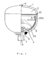
- Fig. 1 is a view illustrating one example of an accumulator according to a diaphragm of the present invention.
- the accumulator comprises a pair of split-shells 1, 2 and a diaphragm 20 for separating an internal space of the split-shells 1, 2 into a gas chamber 3 and an oil chamber 4.
- 5 is a ring holder
- 6 is a poppet
- 7 is a plug having an oil port 8
- 9 is a gas plug
- 10 is a portion of the split-shells welded by an electron beam.
- the dashed line illustrates the position of the diaphragm when elastically deformed.
- the material of the split-shells 1, 2 is, for example, preferably formed by iron, aluminum alloy and the like.
- the diaphragm 20 comprises three layers, a resin layer 21 for gas shielding and a rubber layer 22 adjacent to the gas chamber and a rubber layer 23 adjacent to the oil chamber, wherein the rubber layers 22, 23 are integrally unified to opposite sides of the resin layer 21.
- the rubber layer 22 adapted to be adjacent to the gas chamber is formed of a rubber composition containing a component (A) mentioned below and the rubber layer 23 adapted to be adjacent to the oil chamber is formed of a rubber composition containing a component (B) mentioned below and this is the most important property:
- the rubber layer 22 adapted to be adjacent to the gas chamber is formed of a rubber composition comprising specific H-NBR (component A).
- specific H-NBR component A
- an AN amount is less than 20%, preferably within 17% to 19%. This means that if an AN amount is not less than 20%, permanent deformation during low-temperature compression is not enough and a rubber of the rubber layer 22 adapted to be adjacent to the gas chamber becomes fatigued, then gas leaking occurs from a caulking spot and a gas-tight property deteriorates.
- the content of the specific H-NBR (component A) in the rubber composition forming the rubber layer 22 adapted to be adjacent to a gas chamber is preferably less than 50% by weight, and more preferably less than 45% by weight, based on the whole rubber composition (solid content).
- carbon black, a vulcanizing agent, an antioxidant, a plasticizing agent, a co-cross-linking agent, zinc oxide, magnesium oxide, stearate and the like may appropriately be added to as well as the specific H-NBR (component A). They may be used alone or in combinations thereof.
- the rubber layer 23 adapted to be adjacent to an oil chamber is formed of a rubber composition comprising the specific H-NBR (component B).
- an AN amount is within 20% to 28%, preferably within 22% to 26%. This means that if an AN amount is less than 20%, resistance to oil of a resin layer 23 adapted to be adjacent to an oil chamber deteriorates and a plasticizing agent and the like of a rubber is extracted by hydraulic oil, then a rubber property of the rubber layer 23 adapted to be adjacent to an oil chamber is deteriorated. Furthermore hydraulic oil permeates into a resin layer and gas peremeability resistance deteriorates. By contrast, if an AN amount is more than 28%, the rubber layer 23 adapted to be adjacent to an oil chamber tends to be fatigued.
- the content of the specific H-NBR (component B) in the rubber composition forming the rubber layer 23 adapted to be adjacent to an oil chamber is preferably not more than 50% by weight, and more preferably not more than 45% by weight based on the whole rubber composition (solid content).
- carbon black, a vulcanizing agent, an antioxidant, a plasticizing agent, a co-cross-linking agent, zinc oxide, magnesium oxide, stearate and the like may appropriately be added to as well as the specific H-NBR (component B). They may be used alone or in combinations thereof.
- the resin layer 21 prevents gas sealed within the gas chamber 3 from permeating through the diaphragm.
- the material for the resin layer 21 is not critical as long as its gas permeability is low. Examples of such a material include ethylene-vinyl alcohol copolymer (EVOH), polyamide resin, polyvinylidene fluoride, polyvinylidene chloride, polyphenylene sulfide, liquid crystal polymer and polyethylene naphthalate. These materials may be used alone or in combinations thereof.
- the resin layer 21 may have a single-layer structure or a multi-layer structure of two or more layers.
- EVOH there is no specific limitation. However, it is preferable to employ an EVOH material wherein ethylene is present in an amount of 20 to 65% by weight and wherein the remainder is vinyl alcohol. Among these, the EVOH material wherein ethylene is present in an amount of 32% by weight is preferably suitable.
- polyamide resin examples include nylon 6, nylon 66, nylon 6-10 and nylon 6-12. These resins are used alone or in combinations thereof. If such polyamide resin contains nylon 6 or nylon 66 as a base, its melting point becomes near to that of the EVOH. Therefore, it is possible to employ various mixtures of nylon 6 or nylon 66 and another polyamide resin. Especially, it is preferable to employ a mixture of the above polyamide resin and a polyolefin resin. Since a polyolefin resin has poor water absorbability in such a mixture, it prevents water absorption by the EVOH. That is, if the EVOH absorbs water, its gas barrier property deteriorates, which can be prevented by the inclusion of a polyolefine resin.
- the diaphragm 20 of the present invention may be produced, for example, in the following manner. That is, the resin layer (or a resin film) 21 for gas shielding is produced by using a resin film having low gas permeability such as EVOH or polyamide resin, or laminating two or more thereof. Secondly, an elastomer adhesive (for example, chlorinated polybutadiene rubber adhesive) is applied on both sides of the resin layer (or the resin film) 21 and the material for forming the rubber layer 22 adjacent to the gas chamber and the material for forming the rubber layer 23 adjacent to the oil chamber are press-formed by a presser and cured so as to be adhered to the resin layer. Thus, the diaphragm 20 having a three layered structure as shown in Fig. 2 is obtained.
- a resin film having low gas permeability such as EVOH or polyamide resin, or laminating two or more thereof.
- an elastomer adhesive for example, chlorinated polybutadiene rubber adhesive
- the resin layer (resin film) 21 of the thus obtained diaphragm 20 of the present invention is usually 50 to 210 ⁇ m in thickness.
- the thickness of the rubber layer 22 adjacent to the gas chamber and the rubber layer 23 adjacent to the oil chamber is usually from 1 to 4 mm, and preferably from 1 to 1.5 mm, respectively.
- the accumulator of the present invention may be produced using the thus obtained diaphragm 20, for example, in the following manner.
- a peripheral edge of the diaphragm 20 is positioned at an edge of an inner circumference of the opening of the lower split-shell 2, one of a pair of split-shells 1, 2, each shaped into a generally hemispherical shape, and fixed by being pinched between a periphery of the ring holder 5 and the edge of the inner circumference of the opening of the lower split-shell 2 so as to be installed on the lower split-shell 2 according to Fig. 1 .
- the opening of an upper split-shell 1, the other of a pair of split-shells is engaged onto the opening of the lower split-shell 2 and welded by electron beam or the like.
- the accumulator shown in Fig. 1 can be produced.
- the shape of the shell in the accumulator of the present invention is not limited to a generally spherical shell formed by engaging the pair of split-shells 1, 2, each having a generally hemispherical shape in Fig. 1 , and includes a conchoidal, a cylinder, a box and the like.
- the resin layer 21 and the rubber layer 22 adapted to be adjacent to a gas chamber, the resin layer 21 and the rubber layer 23 adapted to be adjacent to an oil chamber are respectively bonded using a chlorinated polybutadiene rubber adhesive and this is the most important property.
- chlorinated polybutadiene rubber is used for a main component, but the invention is not limited to this.
- an additive agent except rubber components such as chlorinated polybutadiene rubber and the like to the chlorinated polybutadiene rubber adhesive.
- an additive agent for example, titanium dioxide, dichlorohydrin, carbon black and the like is available. They may be used alone or in combinations thereof.
- a rubber composition comprising rubber components such as acrylonitrile butadiene rubber (NBR), hydrogenated acrylonitrile butadiene rubber (H-NBR), butyl rubber (IIR), halogenated butyl rubber (Cl-IIR, Br-IIR), epichlorohydrin rubber, ethylene propylene rubber (EPM, EPDM) and the like is used. These rubbers are used alone or in combinations thereof.
- carbon black, a vulcanizing agent, an antioxidant, a plasticizing agent, zinc oxide, stearate and the like may appropriately be added to as well as rubber components such as the specific H-NBR. These additives are used alone or in combinations thereof.
- a rubber composition comprising rubber components such as acrylonitrile butadiene rubber (NBR), hydrogenated acrylonitrile butadiene rubber (H-NBR), butyl rubber (IIR), halogenated butyl rubber (Cl-IIR, Br-IIR), epichlorohydrin rubber, ethylene propylene rubber (EPM, EPDM) and the like is used. These rubbers are used alone or in combinations thereof.
- carbon black, a vulcanizing agent, an antioxidant, a plasticizing agent, zinc oxide, stearate and the like may appropriately be added to as well as rubber components such as the specific H-NBR. These additives are used alone or in combinations thereof.
- the resin layer 21 prevents gas sealed within the gas chamber 3 from permeating through the diaphragm.
- the material for the resin layer 21 is not critical as long as its gas permeability is low. Examples of such a material include ethylene-vinyl alcohol copolymer (EVOH), polyamide resin, polyvinylidene fluoride, polyvinylidene chloride, polyphenylene sulfide, liquid crystal polymer and polyethylene naphthalate. These materials may be used alone or in combinations thereof.
- the resin layer 21 may have a single-layer structure or a multi-layer structure of two or more layers.
- EVOH there is no specific limitation. However, it is preferable to employ an EVOH material wherein ethylene is present in an amount of 20 to 65% by weight and wherein the reminder is vinyl alcohol. Among these, the EVOH material wherein ethylene is present in an amount of 32% by weight is preferably suitable.
- polyamide resin examples include nylon 6, nylon 66, nylon 6-10 and nylon 6-12. These resins are used alone or in combinations thereof. If such polyamide resin contains nylon 6 or nylon 66 as a base, its melting point becomes near to that of the EVOH. Therefore, it is possible to employ various mixtures of nylon 6 or nylon 66 and another polyamide resin. Especially, it is preferable to employ a mixture of the above polyamide resin and a polyolefin resin. Since a polyolefin resin has poor water absorbability in such a mixture, it prevents water absorption by the EVOH. That is, if the EVOH absorbs water, its gas barrier property deteriorates, which can be prevented by the inclusion of a polyolefine resin.
- the diaphragm 20 of the present invention may be produced, for example, in the following manner. That is, the resin layer (or a resin film) 21 for gas shielding is produced by using a resin film having low gas permeability such as EVOH or polyamide resin, or laminating two or more thereof. Secondly, a chlorinated polybutadiene rubber adhesive is applied on both sides of the resin layer (or the resin film) 21 and the material for forming the rubber layer 22 adjacent to the gas chamber and the material for forming the rubber layer 23 adjacent to the oil chamber are press-formed by a presser and cured so as to be adhered to the resin layer. Thus, the diaphragm 20 having a three layered structure as shown in Fig. 2 is obtained.
- dipping, spraying, brush painting and the like may be applied to a way of applying chlorinated polybutadiene rubber adhesive.
- the resin layer (resin film) 21 of thus obtained diaphragm 20 of the present invention is usually 50 to 210 ⁇ m in thickness.
- the thickness of the rubber layer 22 adjacent to the gas chamber and the rubber layer 23 adjacent to the oil chamber is usually 1 to 4 mm, preferably 1 to 1.5 mm, respectively.
- the thickness of the adhesion layer (now shown) comprising the chlorinated polybutadiene rubber adhesion is preferably within 2 to 30 ⁇ m, and more preferably within 5 to 10 ⁇ m.
- the accumulator of the present invention may be produced using the thus obtained diaphragm 20, for example, in the following manner.
- a peripheral edge of the diaphragm 20 is positioned at an edge of an inner circumference of the opening of the lower split-shell 2, one of a pair of split-shells 1, 2, each shaped into a generally hemispherical shape, and fixed by being pinched between a periphery of the ring holder 5 and the edge of the inner circumference of the opening of the lower split-shell 2 so as to be installed on the lower split-shell 2 according to Fig. 1 .
- the opening of an upper split-shell 1, the other of a pair of split-shells is engaged onto the opening of the lower split-shell 2 and welded by electron beam or the like.
- the accumulator shown in Fig. 1 can be produced.
- the shape of the shell in the accumulator of the present invention is not limited to a generally spherical shell formed by engaging the pair of split-shells 1, 2, each having a generally hemispherical shape in Fig. 1 , and includes a conchoidal, a cylinder, a box and the like.
- Vulcanizing agent (1) peroxide
- PARCADOX 14-40 Vulcanizing agent (2) manufactured by KAWAGUCHI CHEMICAL CO., LTD., ACTOR Q
- Tensile strength at break (TS), elongation at break (EB), hardness (Hs: JIS A) were evaluated in accordance with JIS K 6250.
- test piece (size: 25 mm x 20 mm, thickness: 2 mm) using the above rubber compositions was dipped in mineral oil (PENTOSIN CHF-11S) under conditions of 100°C x 70 hours, 120°C x 70 hours, and 150°C x 70 hours.
- the change of tensile strength at break ( ⁇ TS), the change of elongation at break ( ⁇ EB), the change of volume ( ⁇ V) and the change of weight ( ⁇ W) were respectively measured in accordance with JIS K 6258.
- EVOH content of ethylene is 32%) and polyamide resin (PA) (nylon 6) were prepared and double-extruded, then resin layer (resin sheet) consisting of a five layered structure comprising PA/EVOH/PA/EVOH/PA and having 0. 2 mm of total thickness was produced.
- chlorinated polybutadiene rubber adhesive from Rohm and Haas Company, P6EF was applied on both sides of the resin layer (the thickness of an adhesion layer after drying is 10 ⁇ m) and each rubber compositions shown in Tables 2 and 3 for forming the rubber layer adjacent to the gas chamber and the rubber layer adjacent to the oil chamber were press-formed by a presser and cured to be adhered together.
- the desired diaphragm was produced in which, the rubber layer adjacent to the gas chamber was 1.3 mm thick and the rubber layer adjacent to the oil chamber was 1.3 mm thick.
- the system (accumulator) shown in Fig. 3 was produced using each diaphragm.
- 40 is a diaphragm
- 43 is a gas chamber
- 44 is an oil chamber.
- nitrogen gas was charged into a gas chamber 43 under the condition of 2.5 MPa (20°C) of charged pressure and mineral oil (PENTOSIN CHF-11S) was filled into an oil chamber 44 and allowed to stand under conditions of 140°C and 6.0 MPa of inner pressure in an oil chamber for 168 hours.
- operating durability test was conducted under -40°C atmosphere and 4.0- 6.0 MPa of operating pressure 10,000 times, then gas charged pressure (20°C) of an accumulator was measured.
- ⁇ which means an amount of a deterioration of charged pressure was not more than -0.36 MPa, ⁇ , from more than -0.36 MPa to not more than -0.40 MPa and ⁇ , not less than -0.40 MPa.
- the system (accumulator) shown in Fig. 3 was produced using each diaphragms. And, nitrogen gas was charged into a gas chamber 43 under the condition of 2.5 MPa (20°C) of charged pressure and mineral oil (PENTOSIN CHF-11S) was filled into an oil chamber 44, then they were allowed to stand under the conditions of 70°C and 6.0 MPa of inner pressure in the oil chamber for 24 hours. After that, oil was removed from the oil chamber 44 and an amount of nitrogen gas penetration from the gas chamber 43 was measured by a measuring cylinder. Each evaluation was shown by ⁇ , which means an amount of nitrogen gas penetration was not more than 5 cc, ⁇ , from more than 5 cc to not more than 6 cc and ⁇ , more than 6 cc.
- an AN amount of H-NBR used for a rubber layer adapted to be adjacent to a gas chamber was less than 20% in all products of Examples, permanent deformation during low-temperature compression and a gas-tight property were improved and an amount of a deterioration of charged pressure may be suppressed.
- An AN amount of H-NBR used for a rubber layer adapted to be adjacent to an oil chamber was within a range from 20 to 28% in all products of Examples, then resistance to oil (swelling property and oil permeability) was improved and an amount of nitrogen gas penetration may be suppressed.
- an AN amount of H-NBR used for a resin layer adapted to be adjacent to a gas chamber in the product of Comparative Example 1 was low, thus a gas-tight property was good but an AN amount of H-NBR used for a rubber layer adapted to be adjacent to an oil chamber was too small, then oil resistance on a side adjacent to an oil chamber and gas peremeability resistance deteriorated.
- an AN amount of H-NBR used for a rubber layer adapted to be adjacent to an oil chamber was low thus oil resistance on a side adjacent to an oil chamber and gas peremeability resistance deteriorated.
- an AN amount used for a rubber layer adapted to be adjacent to an oil chamber was so high that a gas-tight property deteriorated.
- both a gas-tight property of a rubber layer adapted to be adjacent to a gas chamber and resistance to oil of a rubber layer adapted to be adjacent to an oil chamber deteriorated, sufficient function of product could not be gained.
- an AN amount of a rubber layer adapted to be adjacent to a gas chamber was high, thus a gas-tight property deteriorated.
- Vulcanizing agent (peroxide) manufactured by Kayaku Akzo Corporation, PARCADOX 14-40
- EVOH 32% of ethylene content
- PA polyamide resin
- nylon 6 polyamide resin
- a resin layer consisting of a five layered structure comprising PA/EVOH/PA/EVOH/PA and having 0.2 mm of total thickness.
- IPA isopropyl alcohol
- P6EF chlorinated polybutadiene rubber adhesive
- each rubber composition shown in Table 5 for forming the rubber layer adjacent to a gas chamber and the rubber layer adjacent to an oil chamber was cohered by rolls and cured to be adhered to the surface of the above adhesion layer for 170°C x 20 minutes.
- the desired rubber-resin layered product sheet (diaphragm) was produced in which, the rubber layer adjacent to the gas chamber was 1.3 mm thick and the rubber layer adjacent to the oil chamber was 1.3 mm thick.
- a chlorinated polyolefin adhesive manufactured by LORD Far East Corporation, C6108
- a rubber-resin layered product sheet was produced in the same manner as Example 7 except for that.
- Each rubber-resin layered product sheet was dipped into mineral oil (PENTOSIN CHF-11S) for 70 hours under each condition of 100°C, 120°C and 150°C, then taken out, pierced by JIS 3 size of dumbbell and tensile strength at break (TS) and elongation at break (EB) were evaluated in accordance with JIS K 6250.
- the tensile strength at break (TS) and the elongation at break (EB) were evaluated in the same manner before oil dipping (blank).
- a rubber-resin layered product sheet was produced in the same manner as Examples and Comparative Examples. In this case, about one third of the sheet was masked by a film then the chuck part for 180° bond separation test was produced. Then, each rubber-resin layered product sheet was dipped into mineral oil (PENTOSIN CHF-11S) for 70 hours under each condition of 100°C, 120°C and 150°C, then taken out, and a one-inch oblong test piece was produced then a 180° bond separation test was conducted. And also, a 180° bond separation test was conducted in the same manner before oil dipping (blank).
- mineral oil PENTOSIN CHF-11S
- the product of Comparative Example 7 using chlorinated polyolefins adhesive had bigger property deterioration as a result of heat load than the product of Example 7 using a chlorinated polybutadiene rubber adhesive.
- cure phenomenon on the adhesion layer in the product of Comparative Example 7 was strong and the product became very fragile, thus a lot of crack formations were occurred in the resin layer.
- the adhesion layer in the product of Example 7 was flexible thus it was possible to suppress crack formation in the resin layer.
- the diaphragm and accumulator of the present invention can be used for hydraulic systems (hydraulic suspensions, hydraulic automatic clutches, power steering and the like) and the like of automobile vehicles, industrial vehicles and the like.
Landscapes
- Engineering & Computer Science (AREA)
- Physics & Mathematics (AREA)
- Fluid Mechanics (AREA)
- Mechanical Engineering (AREA)
- General Engineering & Computer Science (AREA)
- Supply Devices, Intensifiers, Converters, And Telemotors (AREA)
- Laminated Bodies (AREA)
- Diaphragms And Bellows (AREA)
Abstract
a resin layer for gas shielding;
a rubber layer adapted to be adjacent to a gas chamber, and
a rubber layer adapted to be adjacent to an oil chamber, the rubber layers being formed on opposite sides of the resin layer; wherein
the rubber layer adapted to be adjacent to the gas chamber is formed of a rubber composition containing a component (A) mentioned below and the rubber layer adapted to be adjacent to the oil chamber is formed of a rubber composition containing a component (B) mentioned below:
(A) a hydrogenated acrylonitrile butadiene rubber in which an amount of a bound acrylonitrile is less than 20%, and
(B) a hydrogenated acrylonitrile butadiene rubber in which an amount of a bound acrylonitrile is set within a range from 20 to 28%.
Description
- The present invention relates to a diaphragm and an accumulator containing the same which is used, for example, in hydraulic systems (hydraulic suspensions, hydraulic automatic clutches, power steering and the like) of vehicles including automobile vehicles and industrial vehicles.
- A hydraulic accumulator using the characteristic of expanding and compressing volume by charge pressure of gas is used for hydraulic systems (for example, hydraulic suspensions, hydraulic automatic clutches, power steering and the like) of automobile vehicles and the like. This accumulator has a pressure accumulating function and generally comprises a metallic shell and a diaphragm installed within the shell for partitioning the internal space of the shell into two chambers (a gas chamber and an oil chamber). The accumulator contains a gas such as nitrogen sealed in the gas chamber. The oil chamber is connected with a hydraulic circuit of the hydraulic system via a circulation hole which is used during operation.
When pressure in the oil chamber of the accumulator becomes higher than that of the gas chamber as a result of hydraulic oil flowing into the oil chamber via the circulation hole, the diaphragm is bent and elastically deformed so that the gas within the gas chamber is compressed and the volume of the gas chamber becomes smaller and, on the other hand, the oil chamber is enlarged and pressure is accumulated in the hydraulic oil. - A rubber diaphragm has been used for the above accumulator in terms of volumetric efficiency, weight and cost. In recent years, to prevent gas infiltration and leakage via the above rubber diaphragm, diaphragms consisting of composites of resin and rubber have been mass produced which are provided with, for example, a resin layer for gas shielding including polyamide resin, ethylene-vinyl alcohol copolymer (EVOH) and the like, a rubber layer adapted to be adjacent to a gas chamber via this resin layer, and a rubber layer adapted to be adjacent to an oil chamber via the above resin layer. Rubber materials for forming both the above rubber layers are selected with respect to the kind of oil used in the hydraulic circuit, for example, when mineral oil is used, in view of the oil resistance to mineral oil, rubber materials such as an acrylonitrile butadiene rubber (NBR), a hydrogenated acrylonitrile butadiene rubber (H-NBR), an epichlorohydrin rubber and the like are used (see, for example,
JP-A-2001-254701 - However, a conventional diaphragm has a problem that a rubber layer adapted to be adjacent to a gas chamber does not have enough permanent deformation during low-temperature compression. Thus the rubber of a rubber layer adapted to be adjacent to a gas chamber becomes worn, resulting in gas leaking from a caulking spot and weakening a gas-tight property. A conventional diaphragm has a problem that a rubber layer adapted to be adjacent to an oil chamber has poor oil resistance (resistance to oil permeability and swelling property). As a result, a plasticizing agent is extracted by a hydraulic oil such as the above mineral oil, rubber property of a rubber layer adapted to be adjacent to an oil chamber tends to deteriorate. Furthermore, when resistance to oil of a rubber layer adapted to be adjacent to an oil chamber is poor, hydraulic oil tends to permeate into a resin layer and resistance to gas permeability deteriorates.
- Under these circumstances, the present invention has been made. That is, an object of the present invention is to provide a diaphragm having excellent gas-tight properties, oil resistance and gas permeability resistance, and further to provide an accumulator using the same.
- In a conventional diaphragm, adhesion of the resin layer and a rubber layer adapted to be adjacent to a gas chamber, and adhesion of the resin layer and a rubber layer adapted to be adjacent to an oil chamber is usually performed by using chlorinated polyolefins adhesives and the like, respectively. A large amount of co-cross-linking agents are combined in order to strengthen adhesion of each rubber layers and resin layer. Therefore, the adhesion layer is hardened by heat during vulcanizing or a similar process. Moreover, there is a problem that the adhesion layer may crack as a result of bending of the diaphragm at the point of use, which spreads into the resin layer and the durability of the product deteriorates.
- Under these circumstances, the present invention has been made. That is, an object of the present invention to provide a diaphragm which suppresses crack formation in a resin layer and also has superior durability, and further to provide an accumulator using the same.
- To accomplish the above object, a first gist of the present invention is to provide a diaphragm comprising: a resin layer for gas shielding; a rubber layer adapted to be adjacent to a gas chamber, and a rubber layer adapted to be adjacent to an oil chamber, the rubber layers being formed on opposite sides of the resin layer; wherein the rubber layer adapted to be adjacent to the gas chamber is formed of a rubber composition containing a component (A) mentioned below and the rubber layer adapted to be adjacent to the oil chamber is formed of a rubber composition containing a component (B) mentioned below:
- (A) a hydrogenated acrylonitrile butadiene rubber in which an amount of a bound acrylonitrile is less than 20%, and
- (B) a hydrogenated acrylonitrile butadiene rubber in which an amount of a bound acrylonitrile is set within a range from 20 to 28%.
- A second gist of the present invention is to provide an accumulator comprising: a shell; and a diaphragm which separates an internal space of the shell into a gas chamber and an oil chamber.
- That is, the present inventors reached the conclusion that a rubber layer adjacent to the gas chamber is formed of a rubber composition mainly comprising a hydrogenated acrylonitrile butadiene rubber (H-NBR) and conducted numerous experiments with respect to the amount of bound acrylonitrile (AN amount) of H-NBR used in a rubber layer adapted to be adjacent to a gas chamber and a rubber layer adapted to be adjacent to an oil chamber. A tendency to fatigue at a low temperature should be prevented because a rubber layer adapted to be adjacent to a gas chamber is caulked. Therefore it is necessary to set a low AN amount of H-NBR for the rubber layer adapted to be adjacent to a gas chamber. By contrast, if an AN amount of H-NBR forming a rubber layer adapted to be adjacent to an oil chamber is low, a rubber adapted to be adjacent to an oil chamber will swell and a plasticizing agent in the rubber will melted into an oil. As a result, a rubber layer adapted to be adjacent to an oil chamber will deteriorate and the rubber property deteriorates. Furthermore, a resin layer and gas permeability deteriorate because of penetration of hydraulic oil. Therefore, it is necessary to prevent melting of a plasticizing agent to an oil by setting a high AN amount of H-NBR forming a rubber layer adapted to be adjacent to an oil chamber and to suppress a deterioration of gas permeability. However, when an AN amount H-NBR forming a rubber layer adapted to be adjacent to an oil chamber is too high, a rubber layer adapted to be adjacent to an oil chamber tends to be fatigued, thus it is necessary to consider the prevention of a plasticizing agent melting to an oil and the balance between suppression of deterioration of gas permeability by penetration of an oil to a resin layer and the prevention of fatigue. The inventors of the present invention did further experiments because of these reasons and found that when a rubber layer adapted to be adjacent to a gas chamber is formed of a rubber composition comprising H-NBR in which an AN amount is less than 20% and a rubber layer adapted to be adjacent to an oil chamber is formed of rubber composition comprising H-NBR in which an AN amount is within a range from 20 to 28%, diaphragm having good operability of suppression of a deterioration of charged pressure, a deterioration of gas permeability and having superior durability can be obtained, thus, the inventors attained the present invention.
- To accomplish the above object, a third gist of the present invention is to provide a diaphragm comprising: a resin layer for gas shielding; a rubber layer adapted to be adjacent to a gas chamber, and a rubber layer adapted to be adjacent to an oil chamber, the rubber layers being formed on opposite sides of the resin layer; wherein the resin layer and the rubber layer adapted to be adjacent to a gas chamber, the resin layer and the rubber layer adapted to be adjacent to an oil chamber are respectively bonded using a chlorinated polybutadiene rubber adhesive.
- A fourth gist of the present invention is to provide an accumulator comprising: a shell; and a diaphragm which separates an internal space of the shell into a gas chamber and an oil chamber.
- That is, the present inventors have intensively studied so as to obtain diaphragm suppressing a crack formation of a resin layer and having superior durability. First, chlorinated polyolefins adhesive and the like used conventionally could not suppress a crack formation sufficiently regardless of the number of experiments which reduced the amount of the co-cross-linking agent, its adhesive property was not enough. Therefore, the inventors focused on adhesive rubber agent (elastomer series) having an excellent flexibility and continued experimentation. The inventors found that a chlorinated polybutadiene rubber adhesive can suppress crack formation in resin layer and has superior durability, thus the present invention has been completed.
- Therefore, a diaphragm of the present invention has a rubber layer adapted to be adjacent to a gas chamber being formed of rubber compositions comprising H-NBR in which an AN amount is less than 20% and a rubber layer adapted to be adjacent to an oil chamber being formed of rubber compositions comprising H-NBR in which an AN amount is within a range from 20 to 28%. That is, the present invention forms a rubber layer adapted to be adjacent to a gas chamber comprising H-NBR in which an AN amount is less than the conventional one, less than 20%, and can improve its permanent deformation during low-temperature compression, suppress gas leaking from a caulking spot of a rubber layer adapted to be adjacent to a gas chamber and improve its gas-tight property. Also, the present invention forms a rubber layer adapted to be adjacent to an oil chamber comprising H-NBR in which an AN amount is higher than the conventional one, within a range from 20% to 28%, and can improve a resistance to oil permeability, suppress a deterioration of a resin layer and this makes it possible to suppress a deterioration of gas permeability.
- Furthermore, if an AN amount of H-NBR used for the rubber compositions of the rubber layer adapted to be adjacent to a gas chamber is set within a range from 17 to 19%, a gas-tight property is more improved.
- As mentioned above, the resin layer and the rubber layer adapted to be adjacent to a gas chamber, the resin layer and the rubber layer adapted to be adjacent to an oil chamber are respectively bonded using a chlorinated polybutadiene rubber adhesive in a diaphragm of the present invention. This chlorinated polybutadiene rubber adhesive has better flexibility and resistance to liquid than a conventional chlorinated polyolefins adhesive and the like. Thus crack formation in an adhesion itself seldom occurs. Therefore, a crack is less likely to be led to a resin layer and this makes product durability superior.
-
-
Fig. 1 is a view (partial sectional view) for illustrating one example of the accumulator of the present invention. -
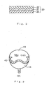
Fig. 2 is an enlarged sectional view of the essential portion for illustrating one example of the diaphragm of the present invention. -
Fig. 3 is a schematic view for illustrating a system (accumulator) using the diaphragm of the present invention. - Embodiments of the present invention will be described in detail below.
-
Fig. 1 is a view illustrating one example of an accumulator according to a diaphragm of the present invention. The accumulator comprises a pair of split-shells 1, 2 and adiaphragm 20 for separating an internal space of the split-shells 1, 2 into agas chamber 3 and anoil chamber 4. InFig. 1 , 5 is a ring holder, 6 is a poppet, 7 is a plug having an oil port 8, 9 is a gas plug, 10 is a portion of the split-shells welded by an electron beam. InFig. 1 , the dashed line illustrates the position of the diaphragm when elastically deformed. - The material of the split-
shells 1, 2 is, for example, preferably formed by iron, aluminum alloy and the like. - The
diaphragm 20 comprises three layers, aresin layer 21 for gas shielding and arubber layer 22 adjacent to the gas chamber and arubber layer 23 adjacent to the oil chamber, wherein the rubber layers 22, 23 are integrally unified to opposite sides of theresin layer 21. - In the first invention, the
rubber layer 22 adapted to be adjacent to the gas chamber is formed of a rubber composition containing a component (A) mentioned below and therubber layer 23 adapted to be adjacent to the oil chamber is formed of a rubber composition containing a component (B) mentioned below and this is the most important property: - (A) a hydrogenated acrylonitrile butadiene rubber in which an amount of a bound acrylonitrile is less than 20%, and
- (B) a hydrogenated acrylonitrile butadiene rubber in which an amount of a bound acrylonitrile is set within a range from 20 to 28%.
- The
rubber layer 22 adapted to be adjacent to the gas chamber is formed of a rubber composition comprising specific H-NBR (component A). In this specific H-NBR (component A), an AN amount is less than 20%, preferably within 17% to 19%. This means that if an AN amount is not less than 20%, permanent deformation during low-temperature compression is not enough and a rubber of therubber layer 22 adapted to be adjacent to the gas chamber becomes fatigued, then gas leaking occurs from a caulking spot and a gas-tight property deteriorates. - Also, the content of the specific H-NBR (component A) in the rubber composition forming the
rubber layer 22 adapted to be adjacent to a gas chamber is preferably less than 50% by weight, and more preferably less than 45% by weight, based on the whole rubber composition (solid content). - For the rubber composition forming the
rubber layer 22 adapted to be adjacent to a gas chamber, carbon black, a vulcanizing agent, an antioxidant, a plasticizing agent, a co-cross-linking agent, zinc oxide, magnesium oxide, stearate and the like may appropriately be added to as well as the specific H-NBR (component A). They may be used alone or in combinations thereof. - Next, the
rubber layer 23 adapted to be adjacent to an oil chamber is formed of a rubber composition comprising the specific H-NBR (component B). In this specific H-NBR (component B), an AN amount is within 20% to 28%, preferably within 22% to 26%. This means that if an AN amount is less than 20%, resistance to oil of aresin layer 23 adapted to be adjacent to an oil chamber deteriorates and a plasticizing agent and the like of a rubber is extracted by hydraulic oil, then a rubber property of therubber layer 23 adapted to be adjacent to an oil chamber is deteriorated. Furthermore hydraulic oil permeates into a resin layer and gas peremeability resistance deteriorates. By contrast, if an AN amount is more than 28%, therubber layer 23 adapted to be adjacent to an oil chamber tends to be fatigued. - The content of the specific H-NBR (component B) in the rubber composition forming the
rubber layer 23 adapted to be adjacent to an oil chamber is preferably not more than 50% by weight, and more preferably not more than 45% by weight based on the whole rubber composition (solid content). - For the rubber composition forming the
rubber layer 23 adapted to be adjacent to an oil chamber, carbon black, a vulcanizing agent, an antioxidant, a plasticizing agent, a co-cross-linking agent, zinc oxide, magnesium oxide, stearate and the like may appropriately be added to as well as the specific H-NBR (component B). They may be used alone or in combinations thereof. - The
resin layer 21 prevents gas sealed within thegas chamber 3 from permeating through the diaphragm. The material for theresin layer 21 is not critical as long as its gas permeability is low. Examples of such a material include ethylene-vinyl alcohol copolymer (EVOH), polyamide resin, polyvinylidene fluoride, polyvinylidene chloride, polyphenylene sulfide, liquid crystal polymer and polyethylene naphthalate. These materials may be used alone or in combinations thereof. Theresin layer 21 may have a single-layer structure or a multi-layer structure of two or more layers. - As for the above EVOH, there is no specific limitation. However, it is preferable to employ an EVOH material wherein ethylene is present in an amount of 20 to 65% by weight and wherein the remainder is vinyl alcohol. Among these, the EVOH material wherein ethylene is present in an amount of 32% by weight is preferably suitable.
- Examples of the above polyamide resin include nylon 6, nylon 66, nylon 6-10 and nylon 6-12. These resins are used alone or in combinations thereof. If such polyamide resin contains nylon 6 or nylon 66 as a base, its melting point becomes near to that of the EVOH. Therefore, it is possible to employ various mixtures of nylon 6 or nylon 66 and another polyamide resin. Especially, it is preferable to employ a mixture of the above polyamide resin and a polyolefin resin. Since a polyolefin resin has poor water absorbability in such a mixture, it prevents water absorption by the EVOH. That is, if the EVOH absorbs water, its gas barrier property deteriorates, which can be prevented by the inclusion of a polyolefine resin.
- The
diaphragm 20 of the present invention may be produced, for example, in the following manner. That is, the resin layer (or a resin film) 21 for gas shielding is produced by using a resin film having low gas permeability such as EVOH or polyamide resin, or laminating two or more thereof. Secondly, an elastomer adhesive (for example, chlorinated polybutadiene rubber adhesive) is applied on both sides of the resin layer (or the resin film) 21 and the material for forming therubber layer 22 adjacent to the gas chamber and the material for forming therubber layer 23 adjacent to the oil chamber are press-formed by a presser and cured so as to be adhered to the resin layer. Thus, thediaphragm 20 having a three layered structure as shown inFig. 2 is obtained. - The resin layer (resin film) 21 of the thus obtained
diaphragm 20 of the present invention is usually 50 to 210 µm in thickness. And the thickness of therubber layer 22 adjacent to the gas chamber and therubber layer 23 adjacent to the oil chamber is usually from 1 to 4 mm, and preferably from 1 to 1.5 mm, respectively. - The accumulator of the present invention may be produced using the thus obtained
diaphragm 20, for example, in the following manner. First, a peripheral edge of thediaphragm 20 is positioned at an edge of an inner circumference of the opening of the lower split-shell 2, one of a pair of split-shells 1, 2, each shaped into a generally hemispherical shape, and fixed by being pinched between a periphery of the ring holder 5 and the edge of the inner circumference of the opening of the lower split-shell 2 so as to be installed on the lower split-shell 2 according toFig. 1 . Next, the opening of an upper split-shell 1, the other of a pair of split-shells, is engaged onto the opening of the lower split-shell 2 and welded by electron beam or the like. Thus, the accumulator shown inFig. 1 can be produced. - The shape of the shell in the accumulator of the present invention is not limited to a generally spherical shell formed by engaging the pair of split-
shells 1, 2, each having a generally hemispherical shape inFig. 1 , and includes a conchoidal, a cylinder, a box and the like. - Next, the second invention will hereinafter be described. In the second invention, the
resin layer 21 and therubber layer 22 adapted to be adjacent to a gas chamber, theresin layer 21 and therubber layer 23 adapted to be adjacent to an oil chamber are respectively bonded using a chlorinated polybutadiene rubber adhesive and this is the most important property. - For the rubber components of chlorinated polybutadiene rubber adhesive, chlorinated polybutadiene rubber is used for a main component, but the invention is not limited to this.
- Also, it is possible to add appropriately an additive agent except rubber components such as chlorinated polybutadiene rubber and the like to the chlorinated polybutadiene rubber adhesive. For this additive agent, for example, titanium dioxide, dichlorohydrin, carbon black and the like is available. They may be used alone or in combinations thereof.
- Next, for the
rubber layer 22 adapted to be adjacent to a gas chamber, for example, a rubber composition comprising rubber components such as acrylonitrile butadiene rubber (NBR), hydrogenated acrylonitrile butadiene rubber (H-NBR), butyl rubber (IIR), halogenated butyl rubber (Cl-IIR, Br-IIR), epichlorohydrin rubber, ethylene propylene rubber (EPM, EPDM) and the like is used. These rubbers are used alone or in combinations thereof. - For the rubber composition forming the
rubber layer 22 adapted to be adjacent to a gas chamber, carbon black, a vulcanizing agent, an antioxidant, a plasticizing agent, zinc oxide, stearate and the like may appropriately be added to as well as rubber components such as the specific H-NBR. These additives are used alone or in combinations thereof. - For the
rubber layer 23 adapted to be adjacent to an oil chamber, for example, a rubber composition comprising rubber components such as acrylonitrile butadiene rubber (NBR), hydrogenated acrylonitrile butadiene rubber (H-NBR), butyl rubber (IIR), halogenated butyl rubber (Cl-IIR, Br-IIR), epichlorohydrin rubber, ethylene propylene rubber (EPM, EPDM) and the like is used. These rubbers are used alone or in combinations thereof. - For the rubber composition forming the
rubber layer 23 adapted to be adjacent to an oil chamber, carbon black, a vulcanizing agent, an antioxidant, a plasticizing agent, zinc oxide, stearate and the like may appropriately be added to as well as rubber components such as the specific H-NBR. These additives are used alone or in combinations thereof. - The
resin layer 21 prevents gas sealed within thegas chamber 3 from permeating through the diaphragm. The material for theresin layer 21 is not critical as long as its gas permeability is low. Examples of such a material include ethylene-vinyl alcohol copolymer (EVOH), polyamide resin, polyvinylidene fluoride, polyvinylidene chloride, polyphenylene sulfide, liquid crystal polymer and polyethylene naphthalate. These materials may be used alone or in combinations thereof. Theresin layer 21 may have a single-layer structure or a multi-layer structure of two or more layers. - As for the above EVOH, there is no specific limitation. However, it is preferable to employ an EVOH material wherein ethylene is present in an amount of 20 to 65% by weight and wherein the reminder is vinyl alcohol. Among these, the EVOH material wherein ethylene is present in an amount of 32% by weight is preferably suitable.
- Examples of the above polyamide resin include nylon 6, nylon 66, nylon 6-10 and nylon 6-12. These resins are used alone or in combinations thereof. If such polyamide resin contains nylon 6 or nylon 66 as a base, its melting point becomes near to that of the EVOH. Therefore, it is possible to employ various mixtures of nylon 6 or nylon 66 and another polyamide resin. Especially, it is preferable to employ a mixture of the above polyamide resin and a polyolefin resin. Since a polyolefin resin has poor water absorbability in such a mixture, it prevents water absorption by the EVOH. That is, if the EVOH absorbs water, its gas barrier property deteriorates, which can be prevented by the inclusion of a polyolefine resin.
- The
diaphragm 20 of the present invention may be produced, for example, in the following manner. That is, the resin layer (or a resin film) 21 for gas shielding is produced by using a resin film having low gas permeability such as EVOH or polyamide resin, or laminating two or more thereof. Secondly, a chlorinated polybutadiene rubber adhesive is applied on both sides of the resin layer (or the resin film) 21 and the material for forming therubber layer 22 adjacent to the gas chamber and the material for forming therubber layer 23 adjacent to the oil chamber are press-formed by a presser and cured so as to be adhered to the resin layer. Thus, thediaphragm 20 having a three layered structure as shown inFig. 2 is obtained. - For example, dipping, spraying, brush painting and the like may be applied to a way of applying chlorinated polybutadiene rubber adhesive.
- The resin layer (resin film) 21 of thus obtained
diaphragm 20 of the present invention is usually 50 to 210 µm in thickness. And the thickness of therubber layer 22 adjacent to the gas chamber and therubber layer 23 adjacent to the oil chamber is usually 1 to 4 mm, preferably 1 to 1.5 mm, respectively. The thickness of the adhesion layer (now shown) comprising the chlorinated polybutadiene rubber adhesion is preferably within 2 to 30 µm, and more preferably within 5 to 10 µm. - The accumulator of the present invention may be produced using the thus obtained
diaphragm 20, for example, in the following manner. First, a peripheral edge of thediaphragm 20 is positioned at an edge of an inner circumference of the opening of the lower split-shell 2, one of a pair of split-shells 1, 2, each shaped into a generally hemispherical shape, and fixed by being pinched between a periphery of the ring holder 5 and the edge of the inner circumference of the opening of the lower split-shell 2 so as to be installed on the lower split-shell 2 according toFig. 1 . Next, the opening of an upper split-shell 1, the other of a pair of split-shells, is engaged onto the opening of the lower split-shell 2 and welded by electron beam or the like. Thus, the accumulator shown inFig. 1 can be produced. - The shape of the shell in the accumulator of the present invention is not limited to a generally spherical shell formed by engaging the pair of split-
shells 1, 2, each having a generally hemispherical shape inFig. 1 , and includes a conchoidal, a cylinder, a box and the like. - Examples will be described below along with comparative Examples. However, the present invention is not limited to these Examples.
- First, prior to preparation of the Examples and Comparative Examples, rubber compositions were prepared.
- The components shown in the following Table 1 were mixed together in ratios shown in the same Table and then kneaded using a roller to prepare rubber compositions.
-
Table 1 (Parts by weight) Rubber composition 1 2 3 4 5 6 H-NBR (1): AN amount 36% - - 10 10 20 50 H-NBR (2): AN amount 25% - - - 90 80 50 H-NBR (3): AN amount 19% - - 90 - - - H-NBR (4): AN amount 19% - 100 - - - - H-NBR (5): AN amount 17% 100 - - - - - Stearic acid 1 1 1 1 1 1 Zinc oxide 5 5 5 5 5 5 Magnesium oxide 5 5 5 5 5 5 Antioxidant (1) 1 1 1 1 1 1 Antioxidant (2) 1 1 1 1 1 1 Carbon black 70 70 70 60 60 60 Plasticizing agent 28 28 28 18 18 18 Vulcanizing agent (1) 12 12 6 6 6 6 Co-cross-linking agent 7.5 7.5 7.5 7.5 7.5 7.5 Vulcanizing agent (2) 0.1 0.1 0.1 0.1 0.1 0.1 Total AN amount (%) Polymer fraction 17 43 19 43 20 45 26 49 28 49 30 49 Initial physical properties TS (MPa) 11.0 13.2 10.3 17.0 17.2 18.5 EB (%) 240 272 300 372 367 377 Hs (JIS A) 55 57 57 61 62 64 100°C x 70 hours ΔTS (%) -9.1 -0.8 16.2 -0.4 4.3 0.7 ΔEB (%) -8.3 -4.4 -10.7 4.3 2.5 -4.5 ΔV (%) 12.0 9.9 2.3 -0.2 -0.4 0.4 ΔW (%) 8.0 4.9 0.2 -1.1 -1.1 -0.6 120°C x 70 hours ΔTS (%) -13.6 0.0 15.5 1.4 3.5 2.6 ΔEB (%) -16.7 -11.8 -2.7 -7.5 -3.0 -3.4 ΔV (%) 12.0 10.2 1.5 0.5 0.8 -0.2 ΔW (%) 9.0 5.7 -0.4 -0.5 -0.8 -1.0 150°C x 70 hours ΔTS (%) -18.2 -3.8 12.3 4.9 4.1 2.3 ΔEB (%) -16.7 -8.8 -17.3 2.2 -5.2 - 11.9 ΔV (%) 12.0 9.9 3.4 1.1 1.4 0.7 ΔW (%) 8.0 4.9 1.0 -0.3 -0.5 -1.1 Permanent deformation during low-temperature compression 28 30 46 49 58 74 - Materials shown in the above Table 1 are as follows.
- H-NBR (1)
manufactured by ZEON CORPORATION, ZETPOL 2020 (AN amount: 36%)
H-NBR (2)
manufactured by ZEON CORPORATION, ZETPOL 3120 (AN amount: 25%)
H-NBR (3)
manufactured by ZEON CORPORATION, ZETPOL 4320 (AN amount: 19%)
H-NBR (4)
manufactured by ZEON CORPORATION, ZETPOL 4300 (AN amount: 19%)
H-NBR (5)
manufactured by ZEON CORPORATION, ZETPOL 4110 (AN amount: 17%) - Antioxidant (1)
manufactured by Sumitomo Chemical Co., Ltd., SUMILIZER MB
Antioxidant (2)
manufactured by OUCHI SHINKO CHEMICAL INDUSTRIAL CO., LTD.,
NOCRAC CD - Carbon black
manufactured by Asahi Carbon Co., Ltd., ASAHI # 35 - Plasticizing agent
manufactured by Chisso Corporation, Dioctyl Phthalate - Vulcanizing agent (1) (peroxide)
manufactured by Kayaku Akzo Corporation, PARCADOX 14-40 Vulcanizing agent (2)
manufactured by KAWAGUCHI CHEMICAL CO., LTD., ACTOR Q - Co-cross-linking agent
manufactured by SEIKO CHEMICAL CO., LTD., HI-CROSS M - Each property evaluation of the thus obtained rubber compositions was carried out in accordance with a following standard. The results are also shown in the above Table 1.
- Tensile strength at break (TS), elongation at break (EB), hardness (Hs: JIS A) were evaluated in accordance with JIS K 6250.
- The test piece (size: 25 mm x 20 mm, thickness: 2 mm) using the above rubber compositions was dipped in mineral oil (PENTOSIN CHF-11S) under conditions of 100°C x 70 hours, 120°C x 70 hours, and 150°C x 70 hours. The change of tensile strength at break (ΔTS), the change of elongation at break (ΔEB), the change of volume (ΔV) and the change of weight (ΔW) were respectively measured in accordance with JIS K 6258.
- Elastic retention (%) under condition of -30°C x 22 hours was measured and calculated in accordance with JIS K 6261 by using test piece of each rubber compositions (column: diameter 29.0 mm, height: 12.7 mm).
- According to the result of the above Table 1, resistance to mineral oil and heat resistance of H-NBR were improved when an AN amount became higher, by contrast, permanent deformation during low-temperature compression deteriorated.
- Next, a diaphragm was produced by using the above rubber compositions, in the following manner.
- First, EVOH (content of ethylene is 32%) and polyamide resin (PA) (nylon 6) were prepared and double-extruded, then resin layer (resin sheet) consisting of a five layered structure comprising PA/EVOH/PA/EVOH/PA and having 0. 2 mm of total thickness was produced. Next, chlorinated polybutadiene rubber adhesive (From Rohm and Haas Company, P6EF) was applied on both sides of the resin layer (the thickness of an adhesion layer after drying is 10 µm) and each rubber compositions shown in Tables 2 and 3 for forming the rubber layer adjacent to the gas chamber and the rubber layer adjacent to the oil chamber were press-formed by a presser and cured to be adhered together. Thus, the desired diaphragm was produced in which, the rubber layer adjacent to the gas chamber was 1.3 mm thick and the rubber layer adjacent to the oil chamber was 1.3 mm thick.
-
Table 2 Examples 1 2 3 4 5 6 Rubber layer adjacent to gas chamber Rubber composition 1 Rubber composition 2Rubber composition 1 Rubber composition 2Rubber composition 1 Rubber composition 2AN amount (%) 17 19 17 19 17 19 Rubber layer adjacent to oil chamber Rubber composition 3 Rubber composition 3Rubber composition 4Rubber composition 4Rubber composition 5 Rubber composition 5 AN amount (%) 20 20 26 26 28 28 Amount of deterioration of charged pressure (MPa) -0.12 -0.17 -0.21 -0.3 -0.28 -0.36 ○ ○ ○ ○ ○ ○ Amount of nitrogen gas permeability (cc) 5.7 5.8 4.3 4.2 3.8 3.9 △ △ ○ ○ ○ ○ -
Table 3 Comparative Examples 1 2 3 4 5 6 Rubber layer adjacent to gas chamber Rubber composition 1 3 2 Rubber composition Rubber composition Rubber composition 3 Rubber composition 3Rubber composition 6 AN amount (%) 17 20 19 20 20 30 Rubber layer adjacent to oil chamber Rubber composition 1 2 6 Rubber composition Rubber composition Rubber composition 3 Rubber composition 5 Rubber composition 6 AN amount (%) 17 19 30 20 28 30 Amount of deterioration of charged pressure (MPa) -0.06 -0.22 -0.42 -0.38 -0.47 -0.72 ○ ○ × △ × × Amount of nitrogen gas permeability (cc) 6.7 6.2 3.6 5.7 3.9 3.5 × × ○ △ ○ ○ - Each property evaluation of the thus obtained products of Examples and Comparative Examples was carried out in accordance with a following standard. The results are also shown in the above Table 2 and Table 3.
- The system (accumulator) shown in
Fig. 3 was produced using each diaphragm. InFig.3 , 40 is a diaphragm, 43 is a gas chamber and 44 is an oil chamber. And, nitrogen gas was charged into agas chamber 43 under the condition of 2.5 MPa (20°C) of charged pressure and mineral oil (PENTOSIN CHF-11S) was filled into anoil chamber 44 and allowed to stand under conditions of 140°C and 6.0 MPa of inner pressure in an oil chamber for 168 hours. After that, operating durability test was conducted under -40°C atmosphere and 4.0- 6.0 MPa of operating pressure 10,000 times, then gas charged pressure (20°C) of an accumulator was measured. Each evaluation was shown by ○, which means an amount of a deterioration of charged pressure was not more than -0.36 MPa, △, from more than -0.36 MPa to not more than -0.40 MPa and ×, not less than -0.40 MPa. - The system (accumulator) shown in
Fig. 3 was produced using each diaphragms. And, nitrogen gas was charged into agas chamber 43 under the condition of 2.5 MPa (20°C) of charged pressure and mineral oil (PENTOSIN CHF-11S) was filled into anoil chamber 44, then they were allowed to stand under the conditions of 70°C and 6.0 MPa of inner pressure in the oil chamber for 24 hours. After that, oil was removed from theoil chamber 44 and an amount of nitrogen gas penetration from thegas chamber 43 was measured by a measuring cylinder. Each evaluation was shown by ○, which means an amount of nitrogen gas penetration was not more than 5 cc, △, from more than 5 cc to not more than 6 cc and ×, more than 6 cc. - From the above results, an AN amount of H-NBR used for a rubber layer adapted to be adjacent to a gas chamber was less than 20% in all products of Examples, permanent deformation during low-temperature compression and a gas-tight property were improved and an amount of a deterioration of charged pressure may be suppressed. An AN amount of H-NBR used for a rubber layer adapted to be adjacent to an oil chamber was within a range from 20 to 28% in all products of Examples, then resistance to oil (swelling property and oil permeability) was improved and an amount of nitrogen gas penetration may be suppressed.
- By contrast, an AN amount of H-NBR used for a resin layer adapted to be adjacent to a gas chamber in the product of Comparative Example 1 was low, thus a gas-tight property was good but an AN amount of H-NBR used for a rubber layer adapted to be adjacent to an oil chamber was too small, then oil resistance on a side adjacent to an oil chamber and gas peremeability resistance deteriorated. In the product of Comparative Example 2, an AN amount of H-NBR used for a rubber layer adapted to be adjacent to an oil chamber was low thus oil resistance on a side adjacent to an oil chamber and gas peremeability resistance deteriorated. In products of Comparative Examples 3 and 6, an AN amount used for a rubber layer adapted to be adjacent to an oil chamber was so high that a gas-tight property deteriorated. In the product of Comparative Example 4, both a gas-tight property of a rubber layer adapted to be adjacent to a gas chamber and resistance to oil of a rubber layer adapted to be adjacent to an oil chamber deteriorated, sufficient function of product could not be gained. In the product of Comparative Example 5, an AN amount of a rubber layer adapted to be adjacent to a gas chamber was high, thus a gas-tight property deteriorated.
- First, prior to preparation of the Examples and Comparative Examples, rubber compositions were prepared.
- The components shown in the following Table 4 were mixed together in ratios shown in the same Table and then kneaded using a roller to prepare rubber compositions.
-
Table 4 Rubber composition 7 H-NBR Amount (parts by weight) 100 AN amount (% by weight) 25 FEF(Fast Extruding Furnace) carbon black 50 Antioxidant (1) 1 Antioxidant (2) 1.5 Vulcanizing agent 8 Plasticizing agent 5 Zinc oxide 5 Stearic acid 0.5 - Materials shown in the above Table 4 are as follows.
- H-NBR
manufactured by ZEON CORPORATION, ZETPOL 3110 (AN amount: 25% by weight) - Carbon black
manufactured by Mitsubishi Chemical Corporation, DIABLACK E - Antioxidant (1) manufactured by Sumitomo Chemical Co., Ltd., SUMILIZER MB Antioxidant (2)
manufactured by OUCHI SHINKO CHEMICAL INDUSTRIAL CO., LTD.,
NOCRAC CD - Vulcanizing agent (peroxide)
manufactured by Kayaku Akzo Corporation, PARCADOX 14-40 - Plasticizing agent
manufactured by Chisso Corporation, Dioctyl Phthalate - Next, a diaphragm was produced by using the above rubber compositions.
- First, EVOH (32% of ethylene content) and a polyamide resin (PA) (nylon 6) were prepared and double-extruded so as to be formed into a resin layer (resin sheet) consisting of a five layered structure comprising PA/EVOH/PA/EVOH/PA and having 0.2 mm of total thickness. Next, the surface was cleaned off by isopropyl alcohol (IPA), and was treated with chlorinated polybutadiene rubber adhesive (From Rohm and Haas Company, P6EF) by dipping and dried by air, then an adhesion layer (10 µm of thickness) was formed on both sides of the above resin layer. Next, each rubber composition shown in Table 5 for forming the rubber layer adjacent to a gas chamber and the rubber layer adjacent to an oil chamber was cohered by rolls and cured to be adhered to the surface of the above adhesion layer for 170°C x 20 minutes. Thus, the desired rubber-resin layered product sheet (diaphragm) was produced in which, the rubber layer adjacent to the gas chamber was 1.3 mm thick and the rubber layer adjacent to the oil chamber was 1.3 mm thick.
- As substitute for the above chlorinated polybutadiene rubber adhesive, a chlorinated polyolefin adhesive (manufactured by LORD Far East Corporation, C6108) was used. A rubber-resin layered product sheet (diaphragm) was produced in the same manner as Example 7 except for that.
-
Table 5 Example 7 Comparative Example 7 Rubber layer adjacent to gas chamber Rubber composition 7 Rubber composition 7Rubber layer adjacent to oil chamber Rubber composition 7 Rubber composition 7Adhesion layer *1 *2 Blank TS (MPa) 10.2 8.2 EB (%) 140 100 Separation mode OK Partially NG Adhesive rupture force (N/inch) 95 178 State of resin layer ⊚ - 100°C x 70 hours TS (MPa) 10.1 7.5 EB (%) 110 80 Separation mode OK OK Adhesive rupture force (N/inch) 105 152 State of resin layer ⊚ × 120°C x 70 hours TS (MPa) 9.2 7.1 EB (%) 100 75 Separation mode OK OK Adhesive rupture force (N/inch) 90 152 State of resin layer ○ × 150°C x 70 hours TS (MPa) 9.6 6.4 EB (%) 85 50 Separation mode OK Entirely NG Adhesive rupture force (N/inch) 70 110 State of resin layer ○ × *1: Chlorinated polybutadiene rubber adhesive (From Rohm and Haas Company, P6EF)
*2: Chlorinated polyolefin adhesive (manufactured by LORD Far East Corporation, C6108) - Each property evaluation of the thus obtained products of Examples and Comparative Examples was carried out in accordance with a following standard. The results were also shown in the above Table 5.
- Each rubber-resin layered product sheet was dipped into mineral oil (PENTOSIN CHF-11S) for 70 hours under each condition of 100°C, 120°C and 150°C, then taken out, pierced by
JIS 3 size of dumbbell and tensile strength at break (TS) and elongation at break (EB) were evaluated in accordance with JIS K 6250. The tensile strength at break (TS) and the elongation at break (EB) were evaluated in the same manner before oil dipping (blank). - A rubber-resin layered product sheet was produced in the same manner as Examples and Comparative Examples. In this case, about one third of the sheet was masked by a film then the chuck part for 180° bond separation test was produced. Then, each rubber-resin layered product sheet was dipped into mineral oil (PENTOSIN CHF-11S) for 70 hours under each condition of 100°C, 120°C and 150°C, then taken out, and a one-inch oblong test piece was produced then a 180° bond separation test was conducted. And also, a 180° bond separation test was conducted in the same manner before oil dipping (blank).
- The appearance of the resin layer after the above bond separation test was observed visually. Each evaluation was shown by ×, which means a lot of crack formations were observed in the resin layer, ○, which means few crack formations were observed in the resin layer and ⊚, which means no crack formation was observed in the resin layer.
- According to the result of the above Table 5, the product of Comparative Example 7 using chlorinated polyolefins adhesive had bigger property deterioration as a result of heat load than the product of Example 7 using a chlorinated polybutadiene rubber adhesive. When the appearance of the resin layer after the bond separation test was observed, cure phenomenon on the adhesion layer in the product of Comparative Example 7 was strong and the product became very fragile, thus a lot of crack formations were occurred in the resin layer. By contrast, the adhesion layer in the product of Example 7 was flexible thus it was possible to suppress crack formation in the resin layer.
- The diaphragm and accumulator of the present invention can be used for hydraulic systems (hydraulic suspensions, hydraulic automatic clutches, power steering and the like) and the like of automobile vehicles, industrial vehicles and the like.
Claims (5)
- A diaphragm comprising:a resin layer for gas shielding;a rubber layer adapted to be adjacent to a gas chamber, anda rubber layer adapted to be adjacent to an oil chamber, the rubber layers being formed on opposite sides of the resin layer; whereinthe rubber layer adapted to be adjacent to the gas chamber is formed of a rubber composition containing a component (A) mentioned below and the rubber layer adapted to be adjacent to the oil chamber is formed of a rubber composition containing a component (B) mentioned below:(A) a hydrogenated acrylonitrile butadiene rubber in which an amount of a bound acrylonitrile is less than 20%, and(B) a hydrogenated acrylonitrile butadiene rubber in which an amount of a bound acrylonitrile is set within a range from 20 to 28%.
- A diaphragm as claimed in claim 1, wherein the amount of the bound acrylonitrile in the hydrogenated acrylonitrile butadiene rubber as the component (A) is set within a range from 17 to 19%.
- An accumulator comprising:a shell; anda diaphragm which separates an internal space of the shell into a gas chamber and an oil chamber; whereinthe diaphragm consists of the diaphragm as claimed in claim 1 or 2.
- A diaphragm comprising:a resin layer for gas shielding;a rubber layer adapted to be adjacent to a gas chamber, anda rubber layer adapted to be adjacent to an oil chamber, the rubber layers being formed on opposite sides of the resin layer; whereinthe resin layer and the rubber layer adapted to be adjacent to a gas chamber, the resin layer and the rubber layer adapted to be adjacent to an oil chamber are respectively bonded using a chlorinated polybutadiene rubber adhesive.
- An accumulator comprising:a shell; anda diaphragm which separates an internal space of the shell into a gas chamber and an oil chamber; whereinthe diaphragm consists of the diaphragm as claimed in claim 4.
Applications Claiming Priority (2)
| Application Number | Priority Date | Filing Date | Title |
|---|---|---|---|
| JP2007255755A JP4937071B2 (en) | 2007-09-28 | 2007-09-28 | Diaphragm and accumulator using the same |
| JP2007255759A JP4937072B2 (en) | 2007-09-28 | 2007-09-28 | Diaphragm and accumulator using the same |
Publications (2)
| Publication Number | Publication Date |
|---|---|
| EP2042299A2 true EP2042299A2 (en) | 2009-04-01 |
| EP2042299A3 EP2042299A3 (en) | 2009-04-15 |
Family
ID=39884763
Family Applications (1)
| Application Number | Title | Priority Date | Filing Date |
|---|---|---|---|
| EP08016998A Withdrawn EP2042299A3 (en) | 2007-09-28 | 2008-09-26 | Diaphragm and accumulator using the same |
Country Status (1)
| Country | Link |
|---|---|
| EP (1) | EP2042299A3 (en) |
Cited By (1)
| Publication number | Priority date | Publication date | Assignee | Title |
|---|---|---|---|---|
| WO2022171367A1 (en) * | 2021-02-13 | 2022-08-18 | Hydac Technology Gmbh | Separating element |
Citations (1)
| Publication number | Priority date | Publication date | Assignee | Title |
|---|---|---|---|---|
| JP2001254701A (en) | 2000-03-14 | 2001-09-21 | Nok Corp | Accumulator bladder |
Family Cites Families (5)
| Publication number | Priority date | Publication date | Assignee | Title |
|---|---|---|---|---|
| JPS60141739A (en) * | 1983-12-29 | 1985-07-26 | Fujikura Rubber Ltd | Rubber composition |
| JPH01177447A (en) * | 1987-12-27 | 1989-07-13 | Toyoda Gosei Co Ltd | Diaphragm |
| FR2685740B1 (en) * | 1991-12-27 | 1994-08-12 | Tokai Rubber Ind Ltd | FLEXIBLE SEPARATION ELEMENT FOR A HYDRAULIC ACCUMULATOR COMPRISING A GAS STOPPER LAYER IN VINYL ETHYLENE-ALCOHOL COPOLYMER AND AN ELASTIC LAYER IN POLYAMIDE RESIN. |
| EP0898076A1 (en) * | 1997-08-19 | 1999-02-24 | Westinghouse Air Brake Company | Abrasion resistant plastic bonded to a diaphragm |
| JP3214426B2 (en) * | 1997-12-25 | 2001-10-02 | 東海ゴム工業株式会社 | Diaphragm and accumulator using the same |
-
2008
- 2008-09-26 EP EP08016998A patent/EP2042299A3/en not_active Withdrawn
Patent Citations (1)
| Publication number | Priority date | Publication date | Assignee | Title |
|---|---|---|---|---|
| JP2001254701A (en) | 2000-03-14 | 2001-09-21 | Nok Corp | Accumulator bladder |
Cited By (1)
| Publication number | Priority date | Publication date | Assignee | Title |
|---|---|---|---|---|
| WO2022171367A1 (en) * | 2021-02-13 | 2022-08-18 | Hydac Technology Gmbh | Separating element |
Also Published As
| Publication number | Publication date |
|---|---|
| EP2042299A3 (en) | 2009-04-15 |
Similar Documents
| Publication | Publication Date | Title |
|---|---|---|
| US10381611B2 (en) | Packaging material for cell | |
| EP1995079B1 (en) | Low permeable rubber laminate and pneumatic tire using same | |
| EP2450184B1 (en) | Laminate | |
| US4806351A (en) | Rubber laminate | |
| EP0759354B1 (en) | Laminate of vulcanizable rubber composition layers, process for producing a vulcanized rubber laminate, and rubber laminate | |
| EP0927631B1 (en) | Diaphragm and accumulator using the same | |
| KR20160070468A (en) | Cell pouch and method of manufacturing the same | |
| WO2005105418A1 (en) | Elastomer compositions for use in a hydrocarbon resistant hose | |
| US7908958B2 (en) | Ballistic resistant laminated structure | |
| US20060270783A1 (en) | Elastomer compositions for use in a hydrocarbon resistant hose | |
| EP1287981B1 (en) | Hose | |
| EP2264086A1 (en) | Molded body for biodiesel fuel | |
| WO2007123220A1 (en) | Layered low-permeability rubber product and pneumatic tire comprising the same | |
| KR101987893B1 (en) | Cell pouch with improved chemical resistance and bending property | |
| EP0348194B1 (en) | Process for preparation of rubber laminate | |
| JP4937071B2 (en) | Diaphragm and accumulator using the same | |
| JP7795074B2 (en) | Fluid transport hose | |
| JP3755328B2 (en) | Diaphragm and accumulator using the same | |
| JP2001206987A (en) | Rubber composition, laminate and hose | |
| JP2001205745A (en) | Laminated body for fuel hose and fuel hose | |
| KR20170075287A (en) | Cell pouch with high chemical resistance and method for manufacturing the same | |
| JP2010071418A (en) | Refrigerant transportation hose | |
| JP2004286193A (en) | Diaphragm and accumulator using the same | |
| JP2747860B2 (en) | Accumulator and bladder for accumulator used therefor | |
| JP2700593B2 (en) | Accumulator and bladder for accumulator used therefor |
Legal Events
| Date | Code | Title | Description |
|---|---|---|---|
| PUAI | Public reference made under article 153(3) epc to a published international application that has entered the european phase |
Free format text: ORIGINAL CODE: 0009012 |
|
| PUAL | Search report despatched |
Free format text: ORIGINAL CODE: 0009013 |
|
| AK | Designated contracting states |
Kind code of ref document: A2 Designated state(s): AT BE BG CH CY CZ DE DK EE ES FI FR GB GR HR HU IE IS IT LI LT LU LV MC MT NL NO PL PT RO SE SI SK TR |
|
| AX | Request for extension of the european patent |
Extension state: AL BA MK RS |
|
| AK | Designated contracting states |
Kind code of ref document: A3 Designated state(s): AT BE BG CH CY CZ DE DK EE ES FI FR GB GR HR HU IE IS IT LI LT LU LV MC MT NL NO PL PT RO SE SI SK TR |
|
| AX | Request for extension of the european patent |
Extension state: AL BA MK RS |
|
| AKX | Designation fees paid | ||
| STAA | Information on the status of an ep patent application or granted ep patent |
Free format text: STATUS: THE APPLICATION IS DEEMED TO BE WITHDRAWN |
|
| 18D | Application deemed to be withdrawn |
Effective date: 20091016 |
|
| REG | Reference to a national code |
Ref country code: DE Ref legal event code: 8566 |