EP2042285A1 - Method and tool for forming an elongate, hollow article of a fiber-reinforced composite material - Google Patents
Method and tool for forming an elongate, hollow article of a fiber-reinforced composite material Download PDFInfo
- Publication number
- EP2042285A1 EP2042285A1 EP20070117229 EP07117229A EP2042285A1 EP 2042285 A1 EP2042285 A1 EP 2042285A1 EP 20070117229 EP20070117229 EP 20070117229 EP 07117229 A EP07117229 A EP 07117229A EP 2042285 A1 EP2042285 A1 EP 2042285A1
- Authority
- EP
- European Patent Office
- Prior art keywords
- tool bar
- tool
- article
- elongate
- anvil
- Prior art date
- Legal status (The legal status is an assumption and is not a legal conclusion. Google has not performed a legal analysis and makes no representation as to the accuracy of the status listed.)
- Granted
Links
- 239000000463 material Substances 0.000 title claims abstract description 12
- 239000003733 fiber-reinforced composite Substances 0.000 title claims abstract description 11
- 238000000034 method Methods 0.000 title claims abstract description 10
- 238000010438 heat treatment Methods 0.000 claims description 3
- 238000001816 cooling Methods 0.000 abstract description 7
- 238000004519 manufacturing process Methods 0.000 description 3
- 238000004804 winding Methods 0.000 description 2
- 239000002131 composite material Substances 0.000 description 1
- 239000007769 metal material Substances 0.000 description 1
- 239000007787 solid Substances 0.000 description 1
Images
Classifications
-
- B—PERFORMING OPERATIONS; TRANSPORTING
- B29—WORKING OF PLASTICS; WORKING OF SUBSTANCES IN A PLASTIC STATE IN GENERAL
- B29C—SHAPING OR JOINING OF PLASTICS; SHAPING OF MATERIAL IN A PLASTIC STATE, NOT OTHERWISE PROVIDED FOR; AFTER-TREATMENT OF THE SHAPED PRODUCTS, e.g. REPAIRING
- B29C53/00—Shaping by bending, folding, twisting, straightening or flattening; Apparatus therefor
- B29C53/80—Component parts, details or accessories; Auxiliary operations
- B29C53/82—Cores or mandrels
- B29C53/821—Mandrels especially adapted for winding and joining
-
- B—PERFORMING OPERATIONS; TRANSPORTING
- B29—WORKING OF PLASTICS; WORKING OF SUBSTANCES IN A PLASTIC STATE IN GENERAL
- B29C—SHAPING OR JOINING OF PLASTICS; SHAPING OF MATERIAL IN A PLASTIC STATE, NOT OTHERWISE PROVIDED FOR; AFTER-TREATMENT OF THE SHAPED PRODUCTS, e.g. REPAIRING
- B29C33/00—Moulds or cores; Details thereof or accessories therefor
- B29C33/76—Cores
-
- B—PERFORMING OPERATIONS; TRANSPORTING
- B29—WORKING OF PLASTICS; WORKING OF SUBSTANCES IN A PLASTIC STATE IN GENERAL
- B29C—SHAPING OR JOINING OF PLASTICS; SHAPING OF MATERIAL IN A PLASTIC STATE, NOT OTHERWISE PROVIDED FOR; AFTER-TREATMENT OF THE SHAPED PRODUCTS, e.g. REPAIRING
- B29C53/00—Shaping by bending, folding, twisting, straightening or flattening; Apparatus therefor
- B29C53/56—Winding and joining, e.g. winding spirally
- B29C53/58—Winding and joining, e.g. winding spirally helically
- B29C53/60—Winding and joining, e.g. winding spirally helically using internal forming surfaces, e.g. mandrels
-
- B—PERFORMING OPERATIONS; TRANSPORTING
- B29—WORKING OF PLASTICS; WORKING OF SUBSTANCES IN A PLASTIC STATE IN GENERAL
- B29K—INDEXING SCHEME ASSOCIATED WITH SUBCLASSES B29B, B29C OR B29D, RELATING TO MOULDING MATERIALS OR TO MATERIALS FOR MOULDS, REINFORCEMENTS, FILLERS OR PREFORMED PARTS, e.g. INSERTS
- B29K2105/00—Condition, form or state of moulded material or of the material to be shaped
- B29K2105/24—Condition, form or state of moulded material or of the material to be shaped crosslinked or vulcanised
- B29K2105/243—Partially cured
Definitions
- the present invention relates generally to a method for forming an elongate, hollow article of a fiber-reinforced composite material.
- the invention also relates to a tool for forming an elongate, hollow article of a fiber-reinforced composite material, comprising an elongate, metallic tool bar having a first end and a second end.
- a metallic core or bar is often used as a mandrel or tool, around which a plurality of layers of a resin-impregnated tape (so called "prepreg") is applied by winding it in an overlapping manner to form a laminated, semi-finished article.
- prepreg resin-impregnated tape
- the cured article is cooled together with the tool bar.
- the cooling phase normally in room temperature, the tool bar shrinks to a certain degree, i. e.
- the cross-sectional area and the length of the tool bar is somewhat reduced, whereas the dimensions of the cured article remain substantially unchanged.
- the shrinkage of the tool bar may cause undesired engagement between the tool bar and the cured article at certain locations along the tool bar due to uncontrolled mutual longitudinal movements of the tool bar and the article during the cooling phase. This may irrevocably damage the article at certain locations when dismantling the same from the tool bar.
- the method of the present invention is characterized by the steps defined in the independent claim 1. Owing to the arrangement of the uncured article laminate on the tool bar such that during the heat-treatment and the cooling phases one end of the laminate engages a support surface of an anvil fixed to the tool bar, the direction of movement of the cured article relative to the tool bar can be controlled to be in only one suitable longitudinal direction which does not affect the cured article.
- a specific tool for carrying out the method of the invention i. e. for forming an elongate, hollow article of a fiber-reinforced composite material, which ensures a controlled longitudinal movement of the cured article relative to the tool bar during the shrinkage phase thereof and a subsequent damage-free dismantling of the cured article from the tool bar.
- the tool of the invention is characterized by the features set forth in the independent claim 3.
- Figs. 1-3 illustrate a tool 10 for forming an elongate, hollow article 12 of a fiber-reinforced composite material, such as a hollow beam or the like for the aircraft manufacturing industries.
- the tool 10 includes an elongate, preferably solid core or bar 14 having a cross-section corresponding to that of the inner space of the article 12 to be formed, and an anvil 16 at one end of the bar 14.
- the anvil 16 is preferably formed integral with the bar 14 in a metallic material.
- the anvil 16 has a radial surface 18 facing the article 12 of fiber-reinforced composite material and defining, as will be explained hereinafter, a support surface for engagement with an inner end of the article 12 being formed.
- the bar 14 may have a constant cross-section or have a slightly tapered configuration from said one end thereof towards its other end and may be curved in at least in one lateral direction.
- the cross-section of the article 12 and thus of the tool bar 14 may be trapezoidal or have any other arbitrary configuration.
- a plurality of layers 20 of resin-impregnated fiber-reinforced web material are applied on the tool bar 14, e.g. by a tape-laying machine (not shown) winding overlapping layers 20 around the tool bar 14.
- prepreg resin-impregnated fiber-reinforced web material
- the inner end of the laminated, uncured article 12 is placed in engagement with the radial support surface 18 of the anvil 16.
- the tool 10 and the uncured article 12 is heated in an oven or an autoclave (not shown) in order to cure the article 12 on the tool bar 14.
- the tool 10 and the cured article 12 are allowed to cool in room temperature. As shown exaggerated in Fig. 2 , the tool 10 will shrink somewhat laterally and longitudinally relative to the cured article 12 in the cooling phase. Due to the fact that the inner end of the cured article 12 is in contact with the support surface 18 of the anvil 16, the longitudinal movement of the cured article 12 relative to the tool bar 14 will be positively controlled to be executed in only one direction during the cooling and dismantling phase of the article 12. This will prevent possible damage to the article 12 caused by a squeezing action between the tool bar 14 and the article 12, when the tool bar 14 shrinks in two opposite longitudinal directions relative to the article 12.
- the support surface 18 of the anvil 16 at one end of the tool bar 14 will push the article 12 in one single direction relative to the tool bar 14, or, in other words, the tool bar 14 will shrink in one single longitudinal direction relative to the article 12 (to the left in Fig. 2 ).
Landscapes
- Engineering & Computer Science (AREA)
- Mechanical Engineering (AREA)
- Moulding By Coating Moulds (AREA)
Abstract
Description
- The present invention relates generally to a method for forming an elongate, hollow article of a fiber-reinforced composite material.
- The invention also relates to a tool for forming an elongate, hollow article of a fiber-reinforced composite material, comprising an elongate, metallic tool bar having a first end and a second end.
- When forming elongate, hollow articles of fiber-reinforced composite material, such as hollow beams or the like for the aircraft manufacturing industries, a metallic core or bar is often used as a mandrel or tool, around which a plurality of layers of a resin-impregnated tape (so called "prepreg") is applied by winding it in an overlapping manner to form a laminated, semi-finished article. After curing of this composite article in a subsequent heat-treatment step, e.g. in an oven or autoclave, the cured article is cooled together with the tool bar. In the cooling phase, normally in room temperature, the tool bar shrinks to a certain degree, i. e. the cross-sectional area and the length of the tool bar is somewhat reduced, whereas the dimensions of the cured article remain substantially unchanged. In some cases, especially where the article and the tool bar is slightly curved in one or two directions and has a lengthwise tapered configuration, the shrinkage of the tool bar may cause undesired engagement between the tool bar and the cured article at certain locations along the tool bar due to uncontrolled mutual longitudinal movements of the tool bar and the article during the cooling phase. This may irrevocably damage the article at certain locations when dismantling the same from the tool bar.
- It is a primary object of the present invention to provide an improved method for forming an elongate, hollow article of a fiber-reinforced composite material which eliminates the above-mentioned drawback of the prior art methods. To this end the method of the present invention is characterized by the steps defined in the independent claim 1. Owing to the arrangement of the uncured article laminate on the tool bar such that during the heat-treatment and the cooling phases one end of the laminate engages a support surface of an anvil fixed to the tool bar, the direction of movement of the cured article relative to the tool bar can be controlled to be in only one suitable longitudinal direction which does not affect the cured article.
- According to another aspect of the invention there is provided a specific tool for carrying out the method of the invention, i. e. for forming an elongate, hollow article of a fiber-reinforced composite material, which ensures a controlled longitudinal movement of the cured article relative to the tool bar during the shrinkage phase thereof and a subsequent damage-free dismantling of the cured article from the tool bar. To this end the tool of the invention is characterized by the features set forth in the independent claim 3.
- Further details of the method and the tool of the invention will be described in the following detailed description with reference to the accompanying drawing.
-
-
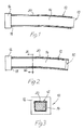
Fig. 1 is a side view of a tool bar with a prepreg laminate applied thereto, in a heated condition when curing the laminate; -
Fig. 2 is side view similar toFig. 1 of the tool bar and the laminate in a cooled condition after the curing step, showing in an exaggerated manner the shrinkage of the tool bar; and -
Fig. 3 is a cross sectional view of the tool bar and the laminate, taken along the line III-III inFig. 2 . -
Figs. 1-3 illustrate atool 10 for forming an elongate,hollow article 12 of a fiber-reinforced composite material, such as a hollow beam or the like for the aircraft manufacturing industries. Thetool 10 includes an elongate, preferably solid core orbar 14 having a cross-section corresponding to that of the inner space of thearticle 12 to be formed, and ananvil 16 at one end of thebar 14. Theanvil 16 is preferably formed integral with thebar 14 in a metallic material. Furthermore, theanvil 16 has aradial surface 18 facing thearticle 12 of fiber-reinforced composite material and defining, as will be explained hereinafter, a support surface for engagement with an inner end of thearticle 12 being formed. Thebar 14 may have a constant cross-section or have a slightly tapered configuration from said one end thereof towards its other end and may be curved in at least in one lateral direction. For example, as shown inFig. 3 , the cross-section of thearticle 12 and thus of thetool bar 14 may be trapezoidal or have any other arbitrary configuration. - In manufacturing for example an elongate hollow beam for an inner support structure of an aircraft control surface a plurality of
layers 20 of resin-impregnated fiber-reinforced web material ("prepreg") are applied on thetool bar 14, e.g. by a tape-laying machine (not shown) winding overlappinglayers 20 around thetool bar 14. The inner end of the laminated,uncured article 12 is placed in engagement with theradial support surface 18 of theanvil 16. Then, thetool 10 and theuncured article 12 is heated in an oven or an autoclave (not shown) in order to cure thearticle 12 on thetool bar 14. - After the curing step the
tool 10 and the curedarticle 12 are allowed to cool in room temperature. As shown exaggerated inFig. 2 , thetool 10 will shrink somewhat laterally and longitudinally relative to the curedarticle 12 in the cooling phase. Due to the fact that the inner end of the curedarticle 12 is in contact with thesupport surface 18 of theanvil 16, the longitudinal movement of the curedarticle 12 relative to thetool bar 14 will be positively controlled to be executed in only one direction during the cooling and dismantling phase of thearticle 12. This will prevent possible damage to thearticle 12 caused by a squeezing action between thetool bar 14 and thearticle 12, when the tool bar 14 shrinks in two opposite longitudinal directions relative to thearticle 12. Thus, in the cooling phase thesupport surface 18 of theanvil 16 at one end of thetool bar 14 will push thearticle 12 in one single direction relative to thetool bar 14, or, in other words, thetool bar 14 will shrink in one single longitudinal direction relative to the article 12 (to the left inFig. 2 ).
Claims (7)
- A method for forming an elongate, hollow article (12) of a fiber-reinforced composite material, comprising the steps of:- providing an elongate, metallic tool bar (14) having a first end and a second end and having a fixed anvil (16) at said first end of the tool bar,- applying at least one layer (20) of a resin-impregnated tape around the tool bar (14) so as to form an uncured article (12) thereon, one end of which engaging a support surface (18) of the fixed anvil (16),- heating the article (12) on the tool bar (14) for curing the article, and- dismantling the cured, cooled article (12) from the tool bar (14) in a direction away from the first end towards the second end of the tool bar (14).
- The method of claim 1, wherein the step of applying resin-impregnated tape around the tool bar (14) includes applying a plurality of overlapping layers (20) thereon.
- A tool (10) for forming an elongate, hollow article (12) of a fiber-reinforced composite material, comprising an elongate, metallic tool bar (14) having a first end and a second end, characterized in that the tool bar (14) is provided with an anvil (16) at the first end thereof, said anvil (16) having a fixed surface (18) protruding radially from the tool bar (14) for supporting an inner end of the article (12) being formed on the tool bar.
- The tool of claim 3, characterized in that the anvil support surface (18) is oriented substantially perpendicular to a longitudinal axis of the tool bar (14).
- The tool of claim 3 or 4, characterized in that the tool bar (14) has a tapered configuration from the first end towards the second end.
- The tool of any one claims 3-5, characterized in that the tool bar (14) is curved in at least in one direction.
- The tool of any one of claims 3-6, characterized in that the anvil (16) is made integral with the tool bar (14).
Priority Applications (3)
| Application Number | Priority Date | Filing Date | Title |
|---|---|---|---|
| EP07117229.0A EP2042285B1 (en) | 2007-09-26 | 2007-09-26 | Method for forming an elongate, hollow article of a fiber-reinforced composite material |
| CA002639758A CA2639758A1 (en) | 2007-09-26 | 2008-09-23 | Method and tool for forming an elongate, hollow article of a fiber-reinforced composite material |
| US12/238,581 US8206532B2 (en) | 2007-09-26 | 2008-09-26 | Method and tool for forming an elongate, hollow article of a fiber-reinforced composite material |
Applications Claiming Priority (1)
| Application Number | Priority Date | Filing Date | Title |
|---|---|---|---|
| EP07117229.0A EP2042285B1 (en) | 2007-09-26 | 2007-09-26 | Method for forming an elongate, hollow article of a fiber-reinforced composite material |
Publications (2)
| Publication Number | Publication Date |
|---|---|
| EP2042285A1 true EP2042285A1 (en) | 2009-04-01 |
| EP2042285B1 EP2042285B1 (en) | 2016-06-22 |
Family
ID=39165832
Family Applications (1)
| Application Number | Title | Priority Date | Filing Date |
|---|---|---|---|
| EP07117229.0A Not-in-force EP2042285B1 (en) | 2007-09-26 | 2007-09-26 | Method for forming an elongate, hollow article of a fiber-reinforced composite material |
Country Status (3)
| Country | Link |
|---|---|
| US (1) | US8206532B2 (en) |
| EP (1) | EP2042285B1 (en) |
| CA (1) | CA2639758A1 (en) |
Cited By (1)
| Publication number | Priority date | Publication date | Assignee | Title |
|---|---|---|---|---|
| DE102017007059A1 (en) * | 2017-07-26 | 2019-01-31 | Bundesrepublik Deutschland, vertreten durch das Bundesministerium der Verteidigung, vertreten durch das Bundesamt für Ausrüstung, Informationstechnik und Nutzung der Bundeswehr | Method for producing a pipe section of a missile outer shell and pipe section of a missile outer shell |
Citations (4)
| Publication number | Priority date | Publication date | Assignee | Title |
|---|---|---|---|---|
| US4110396A (en) | 1974-05-15 | 1978-08-29 | The Gates Rubber Company | Curved tubular articles and method |
| JPS60212331A (en) * | 1984-04-06 | 1985-10-24 | Mitsubishi Heavy Ind Ltd | Mandrel |
| JPS6114938A (en) * | 1984-06-30 | 1986-01-23 | Kubota Ltd | Removing method of core metal at resin tube formation |
| EP1260349A2 (en) * | 2001-05-16 | 2002-11-27 | The Goodyear Tire & Rubber Company | Method and mandrel for forming a curved hose |
Family Cites Families (5)
| Publication number | Priority date | Publication date | Assignee | Title |
|---|---|---|---|---|
| US2794481A (en) * | 1955-02-04 | 1957-06-04 | Smith Corp A O | Method and apparatus for making fiber reinforced resin tubing |
| US3023135A (en) * | 1957-06-05 | 1962-02-27 | White Sewing Machine Corp | Laminated fiber glass radome and method of making same |
| US3115271A (en) * | 1958-08-15 | 1963-12-24 | Minnesota Mining & Mfg | Method of constructing a reinforced resin, cone-shaped structure and product |
| US4997503A (en) * | 1989-07-19 | 1991-03-05 | Phillips Petroleum Company | Filament winding apparatus and method |
| US5779838A (en) * | 1996-04-10 | 1998-07-14 | Fellers; John F. | Method for making a fiber-reinforced structure involving a polymer-impregnated fiber strand |
-
2007
- 2007-09-26 EP EP07117229.0A patent/EP2042285B1/en not_active Not-in-force
-
2008
- 2008-09-23 CA CA002639758A patent/CA2639758A1/en not_active Abandoned
- 2008-09-26 US US12/238,581 patent/US8206532B2/en not_active Expired - Fee Related
Patent Citations (4)
| Publication number | Priority date | Publication date | Assignee | Title |
|---|---|---|---|---|
| US4110396A (en) | 1974-05-15 | 1978-08-29 | The Gates Rubber Company | Curved tubular articles and method |
| JPS60212331A (en) * | 1984-04-06 | 1985-10-24 | Mitsubishi Heavy Ind Ltd | Mandrel |
| JPS6114938A (en) * | 1984-06-30 | 1986-01-23 | Kubota Ltd | Removing method of core metal at resin tube formation |
| EP1260349A2 (en) * | 2001-05-16 | 2002-11-27 | The Goodyear Tire & Rubber Company | Method and mandrel for forming a curved hose |
Cited By (2)
| Publication number | Priority date | Publication date | Assignee | Title |
|---|---|---|---|---|
| DE102017007059A1 (en) * | 2017-07-26 | 2019-01-31 | Bundesrepublik Deutschland, vertreten durch das Bundesministerium der Verteidigung, vertreten durch das Bundesamt für Ausrüstung, Informationstechnik und Nutzung der Bundeswehr | Method for producing a pipe section of a missile outer shell and pipe section of a missile outer shell |
| DE102017007059B4 (en) * | 2017-07-26 | 2021-04-01 | Bundesrepublik Deutschland, vertreten durch das Bundesministerium der Verteidigung, vertreten durch das Bundesamt für Ausrüstung, Informationstechnik und Nutzung der Bundeswehr | Method for producing a pipe section of a missile outer shell and a pipe section of a missile outer shell |
Also Published As
| Publication number | Publication date |
|---|---|
| EP2042285B1 (en) | 2016-06-22 |
| CA2639758A1 (en) | 2009-03-26 |
| US8206532B2 (en) | 2012-06-26 |
| US20090107619A1 (en) | 2009-04-30 |
Similar Documents
| Publication | Publication Date | Title |
|---|---|---|
| KR20220056183A (en) | A method of generating a positive locking force application for a tensile-compression rod, and a tensile-compression rod | |
| JP2010500932A (en) | Manufacturing method of workpiece made of fiber composite material, and fiber composite part in the shape of a deformed material having a cross-sectional contour that varies over the entire length | |
| US6406580B1 (en) | Method for manufacturing composite parts | |
| EP2142357B1 (en) | Method for producing an assembled profile part | |
| CA2651498A1 (en) | Method for manufacturing a composite fibre component using a foldable moulding core, and said moulding core | |
| US20110206875A1 (en) | Method and arrangement for production of an integral hollow-profiled component with fibre composite material | |
| US10744724B2 (en) | Composite aircraft manufacturing tooling and methods using articulating mandrels | |
| EP3290181B1 (en) | A method and system for fabricating a composite structure | |
| KR102143668B1 (en) | Method of fabricating a curved composite structure using composite prepreg tape | |
| EP3613567B1 (en) | Flexible mandrel for forming composite structures | |
| CN104229118B (en) | Fuselage mandrel insert and its method | |
| AU2018236869B2 (en) | Layup tools that facilitate transfer of laminates to cure tools | |
| US9475256B2 (en) | Composite filler | |
| US8206532B2 (en) | Method and tool for forming an elongate, hollow article of a fiber-reinforced composite material | |
| US20200398500A1 (en) | Cutting wire for removal of expanded material after curing of a composite part | |
| EP3296086B1 (en) | Method of producing cored composite parts | |
| EP3756867B1 (en) | Layup and fabrication of tows of braided fiber for hybrid composite parts | |
| US11511512B2 (en) | Layup and fabrication of tows of braided fiber for hybrid composite parts | |
| US11383407B2 (en) | Layup and fabrication of tows of braided fiber for hybrid composite parts | |
| US10279572B2 (en) | Softening strip for controlling stress in joints at very low temperatures | |
| US20130248093A1 (en) | Composite structure forming on coefficient of thermal expansion mismatched tooling | |
| KR101739577B1 (en) | Apparatus and method for reducing thermal stress | |
| WO2007149547A2 (en) | Integrated composite structure | |
| US10569482B2 (en) | Method of manufacturing a strut and a strut formed thereby | |
| BRPI0900028A2 (en) | method and tool for forming an elongated hollow article of fiber reinforced composite material |
Legal Events
| Date | Code | Title | Description |
|---|---|---|---|
| PUAI | Public reference made under article 153(3) epc to a published international application that has entered the european phase |
Free format text: ORIGINAL CODE: 0009012 |
|
| AK | Designated contracting states |
Kind code of ref document: A1 Designated state(s): AT BE BG CH CY CZ DE DK EE ES FI FR GB GR HU IE IS IT LI LT LU LV MC MT NL PL PT RO SE SI SK TR |
|
| AX | Request for extension of the european patent |
Extension state: AL BA HR MK RS |
|
| 17P | Request for examination filed |
Effective date: 20090922 |
|
| 17Q | First examination report despatched |
Effective date: 20091016 |
|
| AKX | Designation fees paid |
Designated state(s): AT BE BG CH CY CZ DE DK EE ES FI FR GB GR HU IE IS IT LI LT LU LV MC MT NL PL PT RO SE SI SK TR |
|
| GRAP | Despatch of communication of intention to grant a patent |
Free format text: ORIGINAL CODE: EPIDOSNIGR1 |
|
| INTG | Intention to grant announced |
Effective date: 20160111 |
|
| GRAS | Grant fee paid |
Free format text: ORIGINAL CODE: EPIDOSNIGR3 |
|
| GRAA | (expected) grant |
Free format text: ORIGINAL CODE: 0009210 |
|
| AK | Designated contracting states |
Kind code of ref document: B1 Designated state(s): AT BE BG CH CY CZ DE DK EE ES FI FR GB GR HU IE IS IT LI LT LU LV MC MT NL PL PT RO SE SI SK TR |
|
| REG | Reference to a national code |
Ref country code: GB Ref legal event code: FG4D |
|
| REG | Reference to a national code |
Ref country code: CH Ref legal event code: EP |
|
| REG | Reference to a national code |
Ref country code: IE Ref legal event code: FG4D |
|
| REG | Reference to a national code |
Ref country code: AT Ref legal event code: REF Ref document number: 807397 Country of ref document: AT Kind code of ref document: T Effective date: 20160715 |
|
| REG | Reference to a national code |
Ref country code: DE Ref legal event code: R096 Ref document number: 602007046705 Country of ref document: DE |
|
| REG | Reference to a national code |
Ref country code: FR Ref legal event code: PLFP Year of fee payment: 10 |
|
| REG | Reference to a national code |
Ref country code: LT Ref legal event code: MG4D |
|
| REG | Reference to a national code |
Ref country code: NL Ref legal event code: MP Effective date: 20160622 |
|
| PG25 | Lapsed in a contracting state [announced via postgrant information from national office to epo] |
Ref country code: LT Free format text: LAPSE BECAUSE OF FAILURE TO SUBMIT A TRANSLATION OF THE DESCRIPTION OR TO PAY THE FEE WITHIN THE PRESCRIBED TIME-LIMIT Effective date: 20160622 Ref country code: FI Free format text: LAPSE BECAUSE OF FAILURE TO SUBMIT A TRANSLATION OF THE DESCRIPTION OR TO PAY THE FEE WITHIN THE PRESCRIBED TIME-LIMIT Effective date: 20160622 |
|
| REG | Reference to a national code |
Ref country code: AT Ref legal event code: MK05 Ref document number: 807397 Country of ref document: AT Kind code of ref document: T Effective date: 20160622 |
|
| PG25 | Lapsed in a contracting state [announced via postgrant information from national office to epo] |
Ref country code: NL Free format text: LAPSE BECAUSE OF FAILURE TO SUBMIT A TRANSLATION OF THE DESCRIPTION OR TO PAY THE FEE WITHIN THE PRESCRIBED TIME-LIMIT Effective date: 20160622 Ref country code: LV Free format text: LAPSE BECAUSE OF FAILURE TO SUBMIT A TRANSLATION OF THE DESCRIPTION OR TO PAY THE FEE WITHIN THE PRESCRIBED TIME-LIMIT Effective date: 20160622 Ref country code: GR Free format text: LAPSE BECAUSE OF FAILURE TO SUBMIT A TRANSLATION OF THE DESCRIPTION OR TO PAY THE FEE WITHIN THE PRESCRIBED TIME-LIMIT Effective date: 20160923 Ref country code: SE Free format text: LAPSE BECAUSE OF FAILURE TO SUBMIT A TRANSLATION OF THE DESCRIPTION OR TO PAY THE FEE WITHIN THE PRESCRIBED TIME-LIMIT Effective date: 20160622 |
|
| PG25 | Lapsed in a contracting state [announced via postgrant information from national office to epo] |
Ref country code: IT Free format text: LAPSE BECAUSE OF FAILURE TO SUBMIT A TRANSLATION OF THE DESCRIPTION OR TO PAY THE FEE WITHIN THE PRESCRIBED TIME-LIMIT Effective date: 20160622 Ref country code: CZ Free format text: LAPSE BECAUSE OF FAILURE TO SUBMIT A TRANSLATION OF THE DESCRIPTION OR TO PAY THE FEE WITHIN THE PRESCRIBED TIME-LIMIT Effective date: 20160622 Ref country code: RO Free format text: LAPSE BECAUSE OF FAILURE TO SUBMIT A TRANSLATION OF THE DESCRIPTION OR TO PAY THE FEE WITHIN THE PRESCRIBED TIME-LIMIT Effective date: 20160622 Ref country code: SK Free format text: LAPSE BECAUSE OF FAILURE TO SUBMIT A TRANSLATION OF THE DESCRIPTION OR TO PAY THE FEE WITHIN THE PRESCRIBED TIME-LIMIT Effective date: 20160622 Ref country code: EE Free format text: LAPSE BECAUSE OF FAILURE TO SUBMIT A TRANSLATION OF THE DESCRIPTION OR TO PAY THE FEE WITHIN THE PRESCRIBED TIME-LIMIT Effective date: 20160622 Ref country code: IS Free format text: LAPSE BECAUSE OF FAILURE TO SUBMIT A TRANSLATION OF THE DESCRIPTION OR TO PAY THE FEE WITHIN THE PRESCRIBED TIME-LIMIT Effective date: 20161022 |
|
| PG25 | Lapsed in a contracting state [announced via postgrant information from national office to epo] |
Ref country code: BE Free format text: LAPSE BECAUSE OF NON-PAYMENT OF DUE FEES Effective date: 20160622 Ref country code: PL Free format text: LAPSE BECAUSE OF FAILURE TO SUBMIT A TRANSLATION OF THE DESCRIPTION OR TO PAY THE FEE WITHIN THE PRESCRIBED TIME-LIMIT Effective date: 20160622 Ref country code: PT Free format text: LAPSE BECAUSE OF FAILURE TO SUBMIT A TRANSLATION OF THE DESCRIPTION OR TO PAY THE FEE WITHIN THE PRESCRIBED TIME-LIMIT Effective date: 20161024 Ref country code: AT Free format text: LAPSE BECAUSE OF FAILURE TO SUBMIT A TRANSLATION OF THE DESCRIPTION OR TO PAY THE FEE WITHIN THE PRESCRIBED TIME-LIMIT Effective date: 20160622 Ref country code: ES Free format text: LAPSE BECAUSE OF FAILURE TO SUBMIT A TRANSLATION OF THE DESCRIPTION OR TO PAY THE FEE WITHIN THE PRESCRIBED TIME-LIMIT Effective date: 20160622 |
|
| REG | Reference to a national code |
Ref country code: DE Ref legal event code: R097 Ref document number: 602007046705 Country of ref document: DE |
|
| REG | Reference to a national code |
Ref country code: DE Ref legal event code: R119 Ref document number: 602007046705 Country of ref document: DE |
|
| PG25 | Lapsed in a contracting state [announced via postgrant information from national office to epo] |
Ref country code: MC Free format text: LAPSE BECAUSE OF FAILURE TO SUBMIT A TRANSLATION OF THE DESCRIPTION OR TO PAY THE FEE WITHIN THE PRESCRIBED TIME-LIMIT Effective date: 20160622 |
|
| PLBE | No opposition filed within time limit |
Free format text: ORIGINAL CODE: 0009261 |
|
| REG | Reference to a national code |
Ref country code: CH Ref legal event code: PL |
|
| STAA | Information on the status of an ep patent application or granted ep patent |
Free format text: STATUS: NO OPPOSITION FILED WITHIN TIME LIMIT |
|
| GBPC | Gb: european patent ceased through non-payment of renewal fee |
Effective date: 20160926 |
|
| 26N | No opposition filed |
Effective date: 20170323 |
|
| PG25 | Lapsed in a contracting state [announced via postgrant information from national office to epo] |
Ref country code: DK Free format text: LAPSE BECAUSE OF FAILURE TO SUBMIT A TRANSLATION OF THE DESCRIPTION OR TO PAY THE FEE WITHIN THE PRESCRIBED TIME-LIMIT Effective date: 20160622 |
|
| REG | Reference to a national code |
Ref country code: IE Ref legal event code: MM4A |
|
| PG25 | Lapsed in a contracting state [announced via postgrant information from national office to epo] |
Ref country code: IE Free format text: LAPSE BECAUSE OF NON-PAYMENT OF DUE FEES Effective date: 20160926 Ref country code: GB Free format text: LAPSE BECAUSE OF NON-PAYMENT OF DUE FEES Effective date: 20160926 Ref country code: CH Free format text: LAPSE BECAUSE OF NON-PAYMENT OF DUE FEES Effective date: 20160930 Ref country code: LI Free format text: LAPSE BECAUSE OF NON-PAYMENT OF DUE FEES Effective date: 20160930 Ref country code: DE Free format text: LAPSE BECAUSE OF NON-PAYMENT OF DUE FEES Effective date: 20170401 |
|
| PG25 | Lapsed in a contracting state [announced via postgrant information from national office to epo] |
Ref country code: SI Free format text: LAPSE BECAUSE OF FAILURE TO SUBMIT A TRANSLATION OF THE DESCRIPTION OR TO PAY THE FEE WITHIN THE PRESCRIBED TIME-LIMIT Effective date: 20160622 Ref country code: LU Free format text: LAPSE BECAUSE OF NON-PAYMENT OF DUE FEES Effective date: 20160926 |
|
| REG | Reference to a national code |
Ref country code: FR Ref legal event code: PLFP Year of fee payment: 11 |
|
| PG25 | Lapsed in a contracting state [announced via postgrant information from national office to epo] |
Ref country code: CY Free format text: LAPSE BECAUSE OF FAILURE TO SUBMIT A TRANSLATION OF THE DESCRIPTION OR TO PAY THE FEE WITHIN THE PRESCRIBED TIME-LIMIT Effective date: 20160622 Ref country code: HU Free format text: LAPSE BECAUSE OF FAILURE TO SUBMIT A TRANSLATION OF THE DESCRIPTION OR TO PAY THE FEE WITHIN THE PRESCRIBED TIME-LIMIT; INVALID AB INITIO Effective date: 20070926 |
|
| PG25 | Lapsed in a contracting state [announced via postgrant information from national office to epo] |
Ref country code: TR Free format text: LAPSE BECAUSE OF FAILURE TO SUBMIT A TRANSLATION OF THE DESCRIPTION OR TO PAY THE FEE WITHIN THE PRESCRIBED TIME-LIMIT Effective date: 20160622 Ref country code: MT Free format text: LAPSE BECAUSE OF NON-PAYMENT OF DUE FEES Effective date: 20160930 |
|
| PG25 | Lapsed in a contracting state [announced via postgrant information from national office to epo] |
Ref country code: BG Free format text: LAPSE BECAUSE OF FAILURE TO SUBMIT A TRANSLATION OF THE DESCRIPTION OR TO PAY THE FEE WITHIN THE PRESCRIBED TIME-LIMIT Effective date: 20160622 |
|
| REG | Reference to a national code |
Ref country code: FR Ref legal event code: PLFP Year of fee payment: 12 |
|
| PGFP | Annual fee paid to national office [announced via postgrant information from national office to epo] |
Ref country code: FR Payment date: 20190918 Year of fee payment: 13 |
|
| PG25 | Lapsed in a contracting state [announced via postgrant information from national office to epo] |
Ref country code: FR Free format text: LAPSE BECAUSE OF NON-PAYMENT OF DUE FEES Effective date: 20200930 |