EP2042278A2 - Robot controller for halting a robot based on the speed of a robot hand portion - Google Patents
Robot controller for halting a robot based on the speed of a robot hand portion Download PDFInfo
- Publication number
- EP2042278A2 EP2042278A2 EP08014715A EP08014715A EP2042278A2 EP 2042278 A2 EP2042278 A2 EP 2042278A2 EP 08014715 A EP08014715 A EP 08014715A EP 08014715 A EP08014715 A EP 08014715A EP 2042278 A2 EP2042278 A2 EP 2042278A2
- Authority
- EP
- European Patent Office
- Prior art keywords
- robot
- traveling rail
- speed
- coordinate system
- coordinate axes
- Prior art date
- Legal status (The legal status is an assumption and is not a legal conclusion. Google has not performed a legal analysis and makes no representation as to the accuracy of the status listed.)
- Granted
Links
Images



Classifications
-
- B—PERFORMING OPERATIONS; TRANSPORTING
- B25—HAND TOOLS; PORTABLE POWER-DRIVEN TOOLS; MANIPULATORS
- B25J—MANIPULATORS; CHAMBERS PROVIDED WITH MANIPULATION DEVICES
- B25J9/00—Program-controlled manipulators
- B25J9/16—Program controls
- B25J9/1674—Program controls characterised by safety, monitoring, diagnostic
-
- B—PERFORMING OPERATIONS; TRANSPORTING
- B25—HAND TOOLS; PORTABLE POWER-DRIVEN TOOLS; MANIPULATORS
- B25J—MANIPULATORS; CHAMBERS PROVIDED WITH MANIPULATION DEVICES
- B25J5/00—Manipulators mounted on wheels or on carriages
- B25J5/02—Manipulators mounted on wheels or on carriages travelling along a guideway
-
- G—PHYSICS
- G05—CONTROLLING; REGULATING
- G05B—CONTROL OR REGULATING SYSTEMS IN GENERAL; FUNCTIONAL ELEMENTS OF SUCH SYSTEMS; MONITORING OR TESTING ARRANGEMENTS FOR SUCH SYSTEMS OR ELEMENTS
- G05B2219/00—Program-control systems
- G05B2219/30—Nc systems
- G05B2219/40—Robotics, robotics mapping to robotics vision
- G05B2219/40248—Manipulator on slide
-
- G—PHYSICS
- G05—CONTROLLING; REGULATING
- G05B—CONTROL OR REGULATING SYSTEMS IN GENERAL; FUNCTIONAL ELEMENTS OF SUCH SYSTEMS; MONITORING OR TESTING ARRANGEMENTS FOR SUCH SYSTEMS OR ELEMENTS
- G05B2219/00—Program-control systems
- G05B2219/30—Nc systems
- G05B2219/40—Robotics, robotics mapping to robotics vision
- G05B2219/40252—Robot on track, rail moves only back and forth
-
- G—PHYSICS
- G05—CONTROLLING; REGULATING
- G05B—CONTROL OR REGULATING SYSTEMS IN GENERAL; FUNCTIONAL ELEMENTS OF SUCH SYSTEMS; MONITORING OR TESTING ARRANGEMENTS FOR SUCH SYSTEMS OR ELEMENTS
- G05B2219/00—Program-control systems
- G05B2219/30—Nc systems
- G05B2219/40—Robotics, robotics mapping to robotics vision
- G05B2219/40272—Manipulator on slide, track
-
- G—PHYSICS
- G05—CONTROLLING; REGULATING
- G05B—CONTROL OR REGULATING SYSTEMS IN GENERAL; FUNCTIONAL ELEMENTS OF SUCH SYSTEMS; MONITORING OR TESTING ARRANGEMENTS FOR SUCH SYSTEMS OR ELEMENTS
- G05B2219/00—Program-control systems
- G05B2219/30—Nc systems
- G05B2219/43—Speed, acceleration, deceleration control ADC
- G05B2219/43201—Limit speed to allowable speed for all axis
-
- G—PHYSICS
- G05—CONTROLLING; REGULATING
- G05B—CONTROL OR REGULATING SYSTEMS IN GENERAL; FUNCTIONAL ELEMENTS OF SUCH SYSTEMS; MONITORING OR TESTING ARRANGEMENTS FOR SUCH SYSTEMS OR ELEMENTS
- G05B2219/00—Program-control systems
- G05B2219/30—Nc systems
- G05B2219/43—Speed, acceleration, deceleration control ADC
- G05B2219/43203—Limitation of speed, permissible, allowable, maximum speed
Definitions
- This invention relates to a robot controller for controlling an industrial robot (hereinafter referred to as "robot”). More specifically, the invention relates to a robot controller for stopping a robot based on the speed of a robot hand portion.
- a robot used in a factory or the like may undergo an abnormal operation, due to abnormal hardware or software. However, it is an accepted practice to bring the robot into an emergency stop when the robot undergoes an abnormal operation.
- Japanese Unexamined Patent Publication JP-A-6-91587 discloses a technology, which determines if the robot is in an abnormal situation when either the acceleration or the speed of the end portion of the robot arm becomes greater than a predetermined value.
- Japanese Unexamined Patent Publication JP-A-10-264080 discloses that if the robot is abnormally operating by comparing an index periodically prepared for detecting abnormal condition such as the moving speed of the tool end point of the robot with a reference value. According to JP-A-6-91587 and JP-A-10-264080 , the robot is stopped when abnormal operation of the robot is detected.
- a robot of the type of the top mount loader includes a traveling rail supported by struts and extending in a horizontal direction, and a robot body attached to a slider that slides on the traveling rail.
- the robot body has a robot hand portion at an end thereof.
- the robot body should move at a high speed along the traveling rail but is not required to move at a high speed in a direction perpendicular to the traveling rail.
- the struts supporting the traveling rail should be strength enough to withstand a maximum speed of the robot body.
- fabricating the struts so as to withstand the maximum speed of the robot body involves a problem of an increase in the cost of producing the struts and the robot.
- This invention was achieved in view of the above-mentioned circumstances and has an object of providing a robot controller which makes it possible to lower the strength required for the struts without limiting the dynamic capability of the robot.
- a robot controller for controlling a robot equipped with a robot hand portion, comprising:
- threshold values are set for each of the coordinate axes of the rectangular coordinate system. Upon suitably setting the threshold values on the coordinate axes, therefore, the robot can be halted in case the moving speed has exceeded the corresponding threshold value. Therefore, there is no need of limiting the dynamic capability of the robot in advance. This avoids the occurrence of such a situation that the robot is not capable of effecting the operation required on the spot.
- a second aspect is concerned with the first aspect, wherein the robot includes a traveling rail supported by struts, and a robot body attached to a slider that slides on the traveling rail; one coordinate axis of the rectangular coordinate system is in parallel with the traveling rail; and the halting means halts the robot in case at least either one of the moving speeds on the remaining coordinate axes of the rectangular coordinate system is higher than the corresponding threshold value.
- the moving speed of the robot hand portion in the direction in parallel with the traveling rail is not compared with the threshold value.
- the robot is halted only when the moving speed in the direction perpendicular to the traveling rail is higher than the threshold value.
- the robot hand portion is allowed to move at its maximum speed in the direction in parallel with the traveling rail but its motion is limited in the direction perpendicular to the traveling rail. This makes it possible to lower the strength required for the struts for supporting the traveling rail.
- a third aspect is concerned with the second aspect, wherein the threshold value of the one coordinate axis in parallel with the traveling rail on the rectangular coordinate system is set to be larger than the threshold values on the remaining coordinate axes.
- the motion of the robot in the direction perpendicular to the traveling rail is suppressed relative to the operation in the direction in parallel with the traveling rail.
- Fig. 1 is a diagram schematically illustrating a robot system equipped with a robot controller according to the invention.
- Fig. 1 illustrates a robot of the type of the top mount loader.
- a traveling rail 12 extending in a horizontal direction is supported at both ends thereof by struts 11.
- a slider 13 is slidably provided on the side surface of the traveling rail 12.
- a robot body 20 comprising a multi-articulated arm is attached to the slider 13.
- the robot body 20 is equipped with a robot hand portion 21 at an end thereof.
- the robot body 20 can be slid along the side surface of the traveling rail 12.
- a robot controller 30 for controlling the robot body 20 is connected to the slider 13.
- the robot controller 30 sets a three-dimensional rectangular coordinate system ⁇ 0. As shown, the Y-axis of the rectangular coordinate system ⁇ 0 is in parallel with the traveling rail 12, the Z-axis is in a vertical direction, and the X-axis is perpendicular to the Y-axis and the Z-axis.
- a teaching control board 40 equipped with an LCD 41 and a keyboard 42 is connected to the robot controller 30.
- the operator is allowed to inspect the data in the robot controller 30 through the LCD 41.
- the keyboard 42 of the teach control board 40 the operator can input and alter various programs and data of the robot controller 30.
- Fig. 2 is a diagram schematically illustrating the robot system shown in Fig. 1 .
- the robot controller 30 has a control unit 31 such as a digital computer that includes a CPU 32 and a storage unit 33.
- the CPU 32 has a function of speed calculation means 36 for calculating the moving speed of the robot hand portion 21 for each of the coordinate axes of the rectangular coordinate system ⁇ 0 and comparator means 38 for comparing the moving speeds of the coordinate axes with predetermined threshold values.
- Threshold values V0x, V0y and V0z on the coordinate axes (X-axis, Y-axis, Z-axis) having a function of a speed limit can be suitably set by the operator through the teach control board 40.
- the threshold values that are set are stored in the storage unit 33 of the robot controller 30.
- the storage unit 33 includes a ROM storing various system programs, a RAM which the CPU 32 uses to temporarily store the data, and a nonvolatile memory for storing various programs related to the contents of operation of the robot, related setpoint values and the above threshold values.
- a servo motor 25 mounted on an arm of the robot body 20 includes a position detector 26 such as an encoder.
- the position detector 26 detects the position of the rotary shaft of the servo motor 25, and transmits the position data to the control unit 31 through a servo amplifier 35.
- the servo amplifier 35 feeds the power to the servo motor 25 of the robot body 20.
- the robot controller 30 includes emergency stop means 34 for interrupting the flow of electric current to the servo amplifier 35 upon receipt of an instruction from the control unit 31.
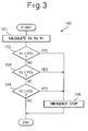
- Fig. 3 is a flowchart illustrating the operation of the robot controller according to the invention. The operation of the robot controller 30 according to the invention will now be described with reference to Fig. 3 .
- the speed of the robot hand portion 21 is calculated at step 101 of the program shown in Fig. 3 .
- speed calculation means 36 periodically calculates the speed V of the robot hand portion 21 based on the position data detected by the position detector 26.
- Fig. 4 is a side view of the robot body, etc.
- the speed calculation means 36 decomposes the calculated speed V for each of the coordinate axes of the rectangular coordinate system ⁇ 0 and from which the speed Vx in the X-axis direction, the speed Vy in the Y-axis direction and the speed Vz in the Z-axis direction can be periodically calculated.
- the Y-axis is in parallel with the traveling rail 12 and, therefore, the speed Vy in the Y-axis direction is not shown in Fig. 4 .
- step 102 it is decided at step 102 if the speed Vx in the X-axis direction is greater than the threshold value V0x related to the X-axis. If the speed Vx is greater than the threshold value V0x, the routine proceeds to step 105 where the emergency stop means 34 interrupts the flow of electric current to the servo amplifier 35. The robot body 20 comes into a halt since the servo motor 25 no longer receives the electric power.
- step 103 it is decided if the speed Vy in the Y-axis direction is greater than the threshold value V0y related to the Y-axis. If the speed Vy is greater than the threshold value V0y, the routine proceeds to step 105 where the emergency stop means 34 halts the robot body 20 in the same manner as above.
- step 104 it is decided if the speed Vz in the Z-axis direction is greater than the threshold value V0z related to the Z-axis. If the speed Vz is greater than the threshold value V0z, the routine proceeds to step 105 where the emergency stop means 34 halts the robot body 20 in the same manner as above.
- the threshold values V0x, V0y and V0z are determined for each of the coordinate axes (X-axis, Y-axis, Z-axis) of the rectangular coordinate system ⁇ 0. Therefore, the robot can be brought into a halt in case any one of the moving speeds Vx, Vy and Vz in the directions of coordinate axes becomes greater than the corresponding threshold value V0x, V0y or V0z.
- suitable threshold values V0x, V0y and V0z are set for the coordinate axes (X-axis, Y-axis, Z-axis)
- the present invention avoids the occurrence of such a situation that the robot is not capable of effecting the operation practically required on the spot such as in the factory or the like place.
- the Y-axis of the rectangular coordinate system ⁇ 0 is set to be in parallel with the traveling rail 12.
- the robot body 20 should be capable of moving in the Y-axis direction at a maximum speed. Therefore, the threshold value V0y related to the speed Vy should be large enough for the struts 11 to withstand the maximum speed of the robot body 20.
- the threshold values V0x and V0z related to the X-axis and the Z-axis perpendicular to the traveling rail 12 do not have to be large enough for the struts 11 to withstand the maximum speed of the robot body 20. Therefore, the threshold values V0x and V0z related to the speed Vx and the speed Vz are, usually, set to be smaller than the threshold value V0y related to the speed Vy.
- the operation of the robot in the direction perpendicular to the traveling rail 12 is suppressed relative to the operation in the direction in parallel with the traveling rail 12. Therefore, it is allowed to lower the strength required for the struts 11 that support the traveling rail 12. Further, it is possible to lower the cost of producing the struts 11 and the robot.
- the robot body 20 of the type of the top mount loader should be capable of moving at its maximum speed in the Y-axis direction.
- the speed Vy in the Y-axis direction does not have to be compared with the threshold value V0y. Therefore, the rectangular coordinate system ⁇ 0 may be a two-dimensional rectangular coordinate system ⁇ 0 comprising the X-axis and the Z-axis, and step 103 of Fig. 3 may be omitted.
- the embodiment in this case is also encompassed in the scope of the invention.
Landscapes
- Engineering & Computer Science (AREA)
- Robotics (AREA)
- Mechanical Engineering (AREA)
- Numerical Control (AREA)
- Manipulator (AREA)
Abstract
Description
- This invention relates to a robot controller for controlling an industrial robot (hereinafter referred to as "robot"). More specifically, the invention relates to a robot controller for stopping a robot based on the speed of a robot hand portion.
- A robot used in a factory or the like may undergo an abnormal operation, due to abnormal hardware or software. However, it is an accepted practice to bring the robot into an emergency stop when the robot undergoes an abnormal operation.
- Japanese Unexamined Patent Publication
JP-A-6-91587 JP-A-10-264080 JP-A-6-91587 JP-A-10-264080 - A robot of the type of the top mount loader includes a traveling rail supported by struts and extending in a horizontal direction, and a robot body attached to a slider that slides on the traveling rail. The robot body has a robot hand portion at an end thereof. In the robot of the type of the top mount loader as described above, there is a case in which the robot body should move at a high speed along the traveling rail but is not required to move at a high speed in a direction perpendicular to the traveling rail.
- However, it is not proper to exclude the probability of motion of the robot body in the direction perpendicular to the traveling rail by taking the safety into consideration. Therefore, the struts supporting the traveling rail should be strength enough to withstand a maximum speed of the robot body. However, fabricating the struts so as to withstand the maximum speed of the robot body involves a problem of an increase in the cost of producing the struts and the robot.
- On the contrary, it is also allowable to adjust the robot so that it cannot exhibit its dynamic capability to its maximum degree in order to lower the strength required for the struts. However, this also results in a decrease in the moving speed of the robot of the type of the top mount loader along the traveling rail, which is the most important requirement. If the dynamic capability of the robot is limited in advance, therefore, there often occurs such a situation that the robot is not capable of effecting the operation practically required on the spot such as in the factory or the like place.
- This invention was achieved in view of the above-mentioned circumstances and has an object of providing a robot controller which makes it possible to lower the strength required for the struts without limiting the dynamic capability of the robot.
- In order to achieve the above object according to a first aspect, there is provided a robot controller for controlling a robot equipped with a robot hand portion, comprising:
- speed calculation means for calculating moving speeds of the robot hand portion on the coordinate axes of a rectangular coordinate system set for the robot controller;
- comparator means for comparing the moving speeds on the coordinate axes calculated by the speed calculation means with threshold values on the coordinate axes of the rectangular coordinate system, respectively; and
- halting means for halting the robot in case at least any one of the moving speeds is higher than the corresponding threshold value.
- In other words, according to the first aspect, threshold values are set for each of the coordinate axes of the rectangular coordinate system. Upon suitably setting the threshold values on the coordinate axes, therefore, the robot can be halted in case the moving speed has exceeded the corresponding threshold value. Therefore, there is no need of limiting the dynamic capability of the robot in advance. This avoids the occurrence of such a situation that the robot is not capable of effecting the operation required on the spot.
- A second aspect is concerned with the first aspect, wherein the robot includes a traveling rail supported by struts, and a robot body attached to a slider that slides on the traveling rail;
one coordinate axis of the rectangular coordinate system is in parallel with the traveling rail; and
the halting means halts the robot in case at least either one of the moving speeds on the remaining coordinate axes of the rectangular coordinate system is higher than the corresponding threshold value. - In other words, according to the second aspect, the moving speed of the robot hand portion in the direction in parallel with the traveling rail is not compared with the threshold value. The robot is halted only when the moving speed in the direction perpendicular to the traveling rail is higher than the threshold value. In other words, the robot hand portion is allowed to move at its maximum speed in the direction in parallel with the traveling rail but its motion is limited in the direction perpendicular to the traveling rail. This makes it possible to lower the strength required for the struts for supporting the traveling rail.
- A third aspect is concerned with the second aspect, wherein the threshold value of the one coordinate axis in parallel with the traveling rail on the rectangular coordinate system is set to be larger than the threshold values on the remaining coordinate axes.
- In other words, according to the third aspect, the motion of the robot in the direction perpendicular to the traveling rail is suppressed relative to the operation in the direction in parallel with the traveling rail.
- The above object, features and advantages as well as other objects, features and advantages will become obvious from the detailed description of a typical embodiment of the invention in conjunction with the accompanying drawings.
-
-
Fig. 1 is a diagram schematically illustrating a robot system equipped with a robot controller according to the invention; -
Fig. 2 is a diagram schematically illustrating the robot system shown inFig. 1 ; -
Fig. 3 is a flowchart illustrating the operation of the robot controller according to the invention; and -
Fig. 4 is a side view of a robot body and a strut. - An embodiment of the invention will now be described with reference to the accompanying drawings. In the drawings, the same members are denoted by the same reference numerals. For easy comprehension, the scales of the drawings are suitably varied.
-
Fig. 1 is a diagram schematically illustrating a robot system equipped with a robot controller according to the invention.Fig. 1 illustrates a robot of the type of the top mount loader. As shown, atraveling rail 12 extending in a horizontal direction is supported at both ends thereof bystruts 11. Aslider 13 is slidably provided on the side surface of thetraveling rail 12. - As shown in
Fig. 1 , arobot body 20 comprising a multi-articulated arm is attached to theslider 13. Therobot body 20 is equipped with arobot hand portion 21 at an end thereof. As can be seen fromFig. 1 , therobot body 20 can be slid along the side surface of thetraveling rail 12. - Further, a
robot controller 30 for controlling therobot body 20 is connected to theslider 13. Therobot controller 30 sets a three-dimensional rectangular coordinate system Σ0. As shown, the Y-axis of the rectangular coordinate system Σ0 is in parallel with thetraveling rail 12, the Z-axis is in a vertical direction, and the X-axis is perpendicular to the Y-axis and the Z-axis. - A
teaching control board 40 equipped with anLCD 41 and akeyboard 42 is connected to therobot controller 30. The operator is allowed to inspect the data in therobot controller 30 through theLCD 41. By using thekeyboard 42 of theteach control board 40, the operator can input and alter various programs and data of therobot controller 30. -
Fig. 2 is a diagram schematically illustrating the robot system shown inFig. 1 . As shown inFig. 2 , therobot controller 30 has acontrol unit 31 such as a digital computer that includes aCPU 32 and astorage unit 33. TheCPU 32 has a function of speed calculation means 36 for calculating the moving speed of therobot hand portion 21 for each of the coordinate axes of the rectangular coordinate system Σ0 and comparator means 38 for comparing the moving speeds of the coordinate axes with predetermined threshold values. Threshold values V0x, V0y and V0z on the coordinate axes (X-axis, Y-axis, Z-axis) having a function of a speed limit can be suitably set by the operator through theteach control board 40. - The threshold values that are set are stored in the
storage unit 33 of therobot controller 30. Thestorage unit 33 includes a ROM storing various system programs, a RAM which theCPU 32 uses to temporarily store the data, and a nonvolatile memory for storing various programs related to the contents of operation of the robot, related setpoint values and the above threshold values. - A
servo motor 25 mounted on an arm of therobot body 20 includes aposition detector 26 such as an encoder. Theposition detector 26 detects the position of the rotary shaft of theservo motor 25, and transmits the position data to thecontrol unit 31 through aservo amplifier 35. Theservo amplifier 35 feeds the power to theservo motor 25 of therobot body 20. As shown inFig. 2 , therobot controller 30 includes emergency stop means 34 for interrupting the flow of electric current to theservo amplifier 35 upon receipt of an instruction from thecontrol unit 31. -
Fig. 3 is a flowchart illustrating the operation of the robot controller according to the invention. The operation of therobot controller 30 according to the invention will now be described with reference toFig. 3 . The speed of therobot hand portion 21 is calculated atstep 101 of the program shown inFig. 3 . - Then, speed calculation means 36 periodically calculates the speed V of the
robot hand portion 21 based on the position data detected by theposition detector 26.Fig. 4 is a side view of the robot body, etc. As can be seen fromFig. 4 , the speed calculation means 36 decomposes the calculated speed V for each of the coordinate axes of the rectangular coordinate system Σ0 and from which the speed Vx in the X-axis direction, the speed Vy in the Y-axis direction and the speed Vz in the Z-axis direction can be periodically calculated. In this connection, the Y-axis is in parallel with the travelingrail 12 and, therefore, the speed Vy in the Y-axis direction is not shown inFig. 4 . - Referring to
Fig. 3 again, it is decided atstep 102 if the speed Vx in the X-axis direction is greater than the threshold value V0x related to the X-axis. If the speed Vx is greater than the threshold value V0x, the routine proceeds to step 105 where the emergency stop means 34 interrupts the flow of electric current to theservo amplifier 35. Therobot body 20 comes into a halt since theservo motor 25 no longer receives the electric power. - If the speed Vx is not greater than the threshold value V0x, the routine proceeds to step 103. At
step 103, it is decided if the speed Vy in the Y-axis direction is greater than the threshold value V0y related to the Y-axis. If the speed Vy is greater than the threshold value V0y, the routine proceeds to step 105 where the emergency stop means 34 halts therobot body 20 in the same manner as above. - If the speed Vy is not greater than the threshold value V0y, the routine then proceeds to step 104. At
step 104, it is decided if the speed Vz in the Z-axis direction is greater than the threshold value V0z related to the Z-axis. If the speed Vz is greater than the threshold value V0z, the routine proceeds to step 105 where the emergency stop means 34 halts therobot body 20 in the same manner as above. - In the present invention, the threshold values V0x, V0y and V0z are determined for each of the coordinate axes (X-axis, Y-axis, Z-axis) of the rectangular coordinate system Σ0. Therefore, the robot can be brought into a halt in case any one of the moving speeds Vx, Vy and Vz in the directions of coordinate axes becomes greater than the corresponding threshold value V0x, V0y or V0z. When suitable threshold values V0x, V0y and V0z are set for the coordinate axes (X-axis, Y-axis, Z-axis), thus there is no need for limiting the dynamic capability of the robot in advance. Therefore, the present invention avoids the occurrence of such a situation that the robot is not capable of effecting the operation practically required on the spot such as in the factory or the like place.
- Further, in the embodiment shown in
Fig. 1 , the Y-axis of the rectangular coordinate system Σ0 is set to be in parallel with the travelingrail 12. Thus, therobot body 20 should be capable of moving in the Y-axis direction at a maximum speed. Therefore, the threshold value V0y related to the speed Vy should be large enough for thestruts 11 to withstand the maximum speed of therobot body 20. - On the contrary, the threshold values V0x and V0z related to the X-axis and the Z-axis perpendicular to the traveling
rail 12 do not have to be large enough for thestruts 11 to withstand the maximum speed of therobot body 20. Therefore, the threshold values V0x and V0z related to the speed Vx and the speed Vz are, usually, set to be smaller than the threshold value V0y related to the speed Vy. - Therefore, the operation of the robot in the direction perpendicular to the traveling
rail 12 is suppressed relative to the operation in the direction in parallel with the travelingrail 12. Therefore, it is allowed to lower the strength required for thestruts 11 that support the travelingrail 12. Further, it is possible to lower the cost of producing thestruts 11 and the robot. - Further, as described above, the
robot body 20 of the type of the top mount loader should be capable of moving at its maximum speed in the Y-axis direction. In other words, the speed Vy in the Y-axis direction does not have to be compared with the threshold value V0y. Therefore, the rectangular coordinate system Σ0 may be a two-dimensional rectangular coordinate system Σ0 comprising the X-axis and the Z-axis, and step 103 ofFig. 3 may be omitted. The embodiment in this case is also encompassed in the scope of the invention. - Though the invention was described above by way of a typical embodiment, it will be understood that a person those skill in the art will be able to effect the above alteration, various other modifications, omission and addition without departing from the scope of the invention.
Claims (3)
- A robot controller (30) for controlling a robot equipped with a robot hand portion (21), comprising:speed calculation means (36) for calculating moving speeds of said robot hand portion (21) on the coordinate axes of a rectangular coordinate system set for said robot controller (30);comparator means (38) for comparing said moving speeds on the coordinate axes calculated by said speed calculation means (36) with threshold values on the coordinate axes of said rectangular coordinate system, respectively; andhalting means (34) for halting said robot in case at least any one of said moving speeds is higher than the corresponding threshold value.
- The robot controller according to claim 1, wherein said robot includes a traveling rail (12) supported by struts, and a robot body (21) attached to a slider (13) that slides on said traveling rail (12);
one coordinate axis of said rectangular coordinate system is in parallel with said traveling rail (12); and
said halting means (34) halts said robot in case at least either one of said moving speeds on the remaining coordinate axes of said rectangular coordinate system is higher than the corresponding threshold value. - The robot controller according to claim 2, wherein the threshold value of said one coordinate axis in parallel with said traveling rail (12) on said rectangular coordinate system is set to be larger than the threshold values on said remaining coordinate axes.
Applications Claiming Priority (1)
| Application Number | Priority Date | Filing Date | Title |
|---|---|---|---|
| JP2007251957A JP4291385B2 (en) | 2007-09-27 | 2007-09-27 | Robot controller that stops the robot based on the speed of the robot hand |
Publications (3)
| Publication Number | Publication Date |
|---|---|
| EP2042278A2 true EP2042278A2 (en) | 2009-04-01 |
| EP2042278A3 EP2042278A3 (en) | 2009-08-12 |
| EP2042278B1 EP2042278B1 (en) | 2011-03-23 |
Family
ID=40260620
Family Applications (1)
| Application Number | Title | Priority Date | Filing Date |
|---|---|---|---|
| EP08014715A Active EP2042278B1 (en) | 2007-09-27 | 2008-08-19 | Robot controller for halting a robot based on the speed of a robot hand portion |
Country Status (5)
| Country | Link |
|---|---|
| US (1) | US8145356B2 (en) |
| EP (1) | EP2042278B1 (en) |
| JP (1) | JP4291385B2 (en) |
| CN (1) | CN101396832A (en) |
| DE (1) | DE602008005684D1 (en) |
Cited By (2)
| Publication number | Priority date | Publication date | Assignee | Title |
|---|---|---|---|---|
| US10766078B2 (en) | 2017-09-05 | 2020-09-08 | Fanuc Corporation | Workpiece picking device |
| US11077563B2 (en) | 2017-09-05 | 2021-08-03 | Fanuc Corporation | Workpiece picking device |
Families Citing this family (19)
| Publication number | Priority date | Publication date | Assignee | Title |
|---|---|---|---|---|
| JP5088156B2 (en) * | 2008-02-05 | 2012-12-05 | 株式会社ジェイテクト | Robot safety monitoring device |
| JP4955791B2 (en) * | 2010-04-20 | 2012-06-20 | ファナック株式会社 | Robot system |
| JP2012018046A (en) * | 2010-07-07 | 2012-01-26 | Mitsutoyo Corp | Industrial machine and control method for industrial machine |
| CN103180106B (en) | 2010-10-28 | 2015-06-17 | Abb研究有限公司 | Method and apparatus for monitoring and limiting the velocity of an industrial robot |
| WO2012135732A1 (en) * | 2011-03-30 | 2012-10-04 | Illinois Tool Works Inc. | System for and method of welding large panel assemblies using a welding robot and a pressing component |
| KR101978740B1 (en) * | 2012-02-15 | 2019-05-15 | 삼성전자주식회사 | Tele-operation system and control method thereof |
| JP6398237B2 (en) * | 2014-03-14 | 2018-10-03 | オムロン株式会社 | Radio control terminal, radio control device for control object, emergency stop control program |
| JP6140112B2 (en) | 2014-07-17 | 2017-05-31 | ファナック株式会社 | Robot control system with stop function |
| JP5926346B2 (en) * | 2014-09-25 | 2016-05-25 | ファナック株式会社 | Human cooperation robot system |
| JP6088601B2 (en) * | 2015-08-10 | 2017-03-01 | ファナック株式会社 | Robot controller that suppresses tool tip deflection in robot with traveling axis |
| US10974383B2 (en) * | 2015-10-28 | 2021-04-13 | Siemens Aktiengesellschaft | Method and apparatus for abnormality detection |
| CN109790723B (en) * | 2016-07-15 | 2021-12-31 | 快砖知识产权私人有限公司 | Brick/block laying machine incorporated in a vehicle |
| JP6490031B2 (en) * | 2016-07-29 | 2019-03-27 | ファナック株式会社 | Robot control apparatus and control method |
| JP6585574B2 (en) * | 2016-09-30 | 2019-10-02 | ファナック株式会社 | Production system for collaborative work between workers and robots |
| CN106426205A (en) * | 2016-11-02 | 2017-02-22 | 广东万丰摩轮有限公司 | Clamping arm mechanism used for rim planeness correcting device |
| ES2983350T3 (en) | 2017-01-18 | 2024-10-22 | Siemens Gamesa Renewable Energy As | Wind turbine and corresponding method |
| CN107016209B (en) * | 2017-04-17 | 2020-06-16 | 珞石(山东)智能科技有限公司 | Industrial robot and guide rail collaborative planning method |
| CN109048950A (en) * | 2018-08-17 | 2018-12-21 | 成都跟驰科技有限公司 | The safety control system of automobile with mechanical arm |
| JP7384005B2 (en) * | 2019-11-27 | 2023-11-21 | セイコーエプソン株式会社 | Control method and robot system |
Citations (2)
| Publication number | Priority date | Publication date | Assignee | Title |
|---|---|---|---|---|
| JPH0691587A (en) | 1992-09-08 | 1994-04-05 | Amada Co Ltd | Emergency stopping method and device for industrial robot |
| JPH10264080A (en) | 1997-03-25 | 1998-10-06 | Fanuc Ltd | Robot controller |
Family Cites Families (9)
| Publication number | Priority date | Publication date | Assignee | Title |
|---|---|---|---|---|
| US4734866A (en) * | 1984-07-05 | 1988-03-29 | Siemens Aktiengesellschaft | Computer controller for an industrial multiaxis robot |
| US4718078A (en) | 1985-08-19 | 1988-01-05 | Siemens Aktiengesellschaft | System for controlling motion of a robot |
| JPH03108008A (en) | 1989-09-20 | 1991-05-08 | Shin Meiwa Ind Co Ltd | Industrial robot speed control method |
| US5304906A (en) * | 1989-12-26 | 1994-04-19 | Fanuc Ltd. | Collision detecting method using an observer |
| CA2273729A1 (en) * | 1998-07-14 | 2000-01-14 | Bayer Corporation | Robotics for transporting containers and objects within an automated analytical instrument and service tool for servicing robotics |
| DE10201488A1 (en) | 2002-01-16 | 2003-07-31 | Duerr Systems Gmbh | Method for controlling robot arm movements within limits of space available establishes coordinates of reference points of arms and limits operation |
| DE102004021468A1 (en) * | 2004-04-30 | 2005-11-24 | Kuka Roboter Gmbh | Method for controlling a machine, in particular an industrial robot |
| FR2878461B1 (en) * | 2004-11-30 | 2007-02-09 | Franco Belge Combustibles | NUCLEAR FUEL ASSEMBLY SKELETON WELDING SYSTEM, METHOD OF PROGRAMMING, METHODS OF SKELETON WELDING AND CORRESPONDING ASSEMBLY. |
| JP4168072B2 (en) * | 2006-12-21 | 2008-10-22 | ファナック株式会社 | Robot system |
-
2007
- 2007-09-27 JP JP2007251957A patent/JP4291385B2/en active Active
-
2008
- 2008-08-14 US US12/191,486 patent/US8145356B2/en active Active
- 2008-08-19 DE DE602008005684T patent/DE602008005684D1/en active Active
- 2008-08-19 EP EP08014715A patent/EP2042278B1/en active Active
- 2008-08-22 CN CN200810213312.5A patent/CN101396832A/en active Pending
Patent Citations (2)
| Publication number | Priority date | Publication date | Assignee | Title |
|---|---|---|---|---|
| JPH0691587A (en) | 1992-09-08 | 1994-04-05 | Amada Co Ltd | Emergency stopping method and device for industrial robot |
| JPH10264080A (en) | 1997-03-25 | 1998-10-06 | Fanuc Ltd | Robot controller |
Cited By (2)
| Publication number | Priority date | Publication date | Assignee | Title |
|---|---|---|---|---|
| US10766078B2 (en) | 2017-09-05 | 2020-09-08 | Fanuc Corporation | Workpiece picking device |
| US11077563B2 (en) | 2017-09-05 | 2021-08-03 | Fanuc Corporation | Workpiece picking device |
Also Published As
| Publication number | Publication date |
|---|---|
| EP2042278B1 (en) | 2011-03-23 |
| EP2042278A3 (en) | 2009-08-12 |
| JP2009082997A (en) | 2009-04-23 |
| US8145356B2 (en) | 2012-03-27 |
| CN101396832A (en) | 2009-04-01 |
| JP4291385B2 (en) | 2009-07-08 |
| DE602008005684D1 (en) | 2011-05-05 |
| US20090088898A1 (en) | 2009-04-02 |
Similar Documents
| Publication | Publication Date | Title |
|---|---|---|
| EP2042278B1 (en) | Robot controller for halting a robot based on the speed of a robot hand portion | |
| US8355817B2 (en) | Robot system | |
| US9452532B2 (en) | Robot, device and method for controlling robot, and computer-readable non-transitory recording medium | |
| US9327408B2 (en) | Robot control device detecting contact with external environment | |
| US9821459B2 (en) | Multi-joint robot having function for repositioning arm | |
| EP2047955B1 (en) | Robot operating range setting device | |
| US10442085B2 (en) | Production system for performing cooperative work by operator and robot | |
| EP2783800A2 (en) | Robot system and method for controlling robot system | |
| EP3238893A1 (en) | Robot system | |
| US20090200978A1 (en) | Robot controller having component protecting function and robot control method | |
| KR102418451B1 (en) | Robot control system | |
| US10996654B2 (en) | Servo controller | |
| US10948899B2 (en) | Motor controller that uses an acceleration/deceleration time constant of the motor | |
| CN110919627B (en) | Robot control method and control device | |
| US20180099410A1 (en) | Robot control device having function for limiting speed and/or acceleration of robot | |
| US20150137726A1 (en) | Motor controller for protecting tool and object to be processed in emergency stop | |
| US11141855B2 (en) | Robot system, method of controlling robot arm, recording medium, and method of manufacturing an article | |
| JP5371882B2 (en) | Force control device | |
| CN112440274B (en) | Robot system | |
| US11927936B2 (en) | Safe operation of a multi-axis kinematic system | |
| JP2005103674A (en) | Robot control apparatus and control method | |
| JP7283994B2 (en) | Robot controller and programming device | |
| US20250303569A1 (en) | System, unit, and manufacturing method | |
| JP2002086383A (en) | Robot interference detection device | |
| JP2024092449A (en) | ROBOT SYSTEM, ROBOT CONTROL METHOD, AND PROGRAM |
Legal Events
| Date | Code | Title | Description |
|---|---|---|---|
| PUAI | Public reference made under article 153(3) epc to a published international application that has entered the european phase |
Free format text: ORIGINAL CODE: 0009012 |
|
| AK | Designated contracting states |
Kind code of ref document: A2 Designated state(s): AT BE BG CH CY CZ DE DK EE ES FI FR GB GR HR HU IE IS IT LI LT LU LV MC MT NL NO PL PT RO SE SI SK TR |
|
| AX | Request for extension of the european patent |
Extension state: AL BA MK RS |
|
| PUAL | Search report despatched |
Free format text: ORIGINAL CODE: 0009013 |
|
| AK | Designated contracting states |
Kind code of ref document: A3 Designated state(s): AT BE BG CH CY CZ DE DK EE ES FI FR GB GR HR HU IE IS IT LI LT LU LV MC MT NL NO PL PT RO SE SI SK TR |
|
| AX | Request for extension of the european patent |
Extension state: AL BA MK RS |
|
| 17P | Request for examination filed |
Effective date: 20100115 |
|
| AKX | Designation fees paid |
Designated state(s): DE |
|
| GRAP | Despatch of communication of intention to grant a patent |
Free format text: ORIGINAL CODE: EPIDOSNIGR1 |
|
| GRAS | Grant fee paid |
Free format text: ORIGINAL CODE: EPIDOSNIGR3 |
|
| GRAA | (expected) grant |
Free format text: ORIGINAL CODE: 0009210 |
|
| RAP1 | Party data changed (applicant data changed or rights of an application transferred) |
Owner name: FANUC CORPORATION |
|
| AK | Designated contracting states |
Kind code of ref document: B1 Designated state(s): DE |
|
| REF | Corresponds to: |
Ref document number: 602008005684 Country of ref document: DE Date of ref document: 20110505 Kind code of ref document: P |
|
| REG | Reference to a national code |
Ref country code: DE Ref legal event code: R096 Ref document number: 602008005684 Country of ref document: DE Effective date: 20110505 |
|
| PLBE | No opposition filed within time limit |
Free format text: ORIGINAL CODE: 0009261 |
|
| STAA | Information on the status of an ep patent application or granted ep patent |
Free format text: STATUS: NO OPPOSITION FILED WITHIN TIME LIMIT |
|
| 26N | No opposition filed |
Effective date: 20111227 |
|
| REG | Reference to a national code |
Ref country code: DE Ref legal event code: R097 Ref document number: 602008005684 Country of ref document: DE Effective date: 20111227 |
|
| PGFP | Annual fee paid to national office [announced via postgrant information from national office to epo] |
Ref country code: DE Payment date: 20250724 Year of fee payment: 18 |