EP2042236A1 - Honeycomb structure for slurry coating - Google Patents
Honeycomb structure for slurry coating Download PDFInfo
- Publication number
- EP2042236A1 EP2042236A1 EP07767662A EP07767662A EP2042236A1 EP 2042236 A1 EP2042236 A1 EP 2042236A1 EP 07767662 A EP07767662 A EP 07767662A EP 07767662 A EP07767662 A EP 07767662A EP 2042236 A1 EP2042236 A1 EP 2042236A1
- Authority
- EP
- European Patent Office
- Prior art keywords
- slurry
- fine pores
- honeycomb structure
- cell
- total volume
- Prior art date
- Legal status (The legal status is an assumption and is not a legal conclusion. Google has not performed a legal analysis and makes no representation as to the accuracy of the status listed.)
- Withdrawn
Links
Images


Classifications
-
- B—PERFORMING OPERATIONS; TRANSPORTING
- B01—PHYSICAL OR CHEMICAL PROCESSES OR APPARATUS IN GENERAL
- B01J—CHEMICAL OR PHYSICAL PROCESSES, e.g. CATALYSIS OR COLLOID CHEMISTRY; THEIR RELEVANT APPARATUS
- B01J37/00—Processes, in general, for preparing catalysts; Processes, in general, for activation of catalysts
- B01J37/02—Impregnation, coating or precipitation
- B01J37/0215—Coating
-
- B—PERFORMING OPERATIONS; TRANSPORTING
- B01—PHYSICAL OR CHEMICAL PROCESSES OR APPARATUS IN GENERAL
- B01J—CHEMICAL OR PHYSICAL PROCESSES, e.g. CATALYSIS OR COLLOID CHEMISTRY; THEIR RELEVANT APPARATUS
- B01J35/00—Catalysts, in general, characterised by their form or physical properties
- B01J35/50—Catalysts, in general, characterised by their form or physical properties characterised by their shape or configuration
- B01J35/56—Foraminous structures having flow-through passages or channels, e.g. grids or three-dimensional [3D] monoliths
- B01J35/57—Honeycombs
-
- C—CHEMISTRY; METALLURGY
- C04—CEMENTS; CONCRETE; ARTIFICIAL STONE; CERAMICS; REFRACTORIES
- C04B—LIME, MAGNESIA; SLAG; CEMENTS; COMPOSITIONS THEREOF, e.g. MORTARS, CONCRETE OR LIKE BUILDING MATERIALS; ARTIFICIAL STONE; CERAMICS; REFRACTORIES; TREATMENT OF NATURAL STONE
- C04B35/00—Shaped ceramic products characterised by their composition; Ceramics compositions; Processing powders of inorganic compounds preparatory to the manufacturing of ceramic products
- C04B35/01—Shaped ceramic products characterised by their composition; Ceramics compositions; Processing powders of inorganic compounds preparatory to the manufacturing of ceramic products based on oxide ceramics
- C04B35/16—Shaped ceramic products characterised by their composition; Ceramics compositions; Processing powders of inorganic compounds preparatory to the manufacturing of ceramic products based on oxide ceramics based on silicates other than clay
- C04B35/18—Shaped ceramic products characterised by their composition; Ceramics compositions; Processing powders of inorganic compounds preparatory to the manufacturing of ceramic products based on oxide ceramics based on silicates other than clay rich in aluminium oxide
- C04B35/195—Alkaline earth aluminosilicates, e.g. cordierite or anorthite
-
- C—CHEMISTRY; METALLURGY
- C04—CEMENTS; CONCRETE; ARTIFICIAL STONE; CERAMICS; REFRACTORIES
- C04B—LIME, MAGNESIA; SLAG; CEMENTS; COMPOSITIONS THEREOF, e.g. MORTARS, CONCRETE OR LIKE BUILDING MATERIALS; ARTIFICIAL STONE; CERAMICS; REFRACTORIES; TREATMENT OF NATURAL STONE
- C04B38/00—Porous mortars, concrete, artificial stone or ceramic ware; Preparation thereof
- C04B38/0006—Honeycomb structures
- C04B38/0009—Honeycomb structures characterised by features relating to the cell walls, e.g. wall thickness or distribution of pores in the walls
-
- C—CHEMISTRY; METALLURGY
- C04—CEMENTS; CONCRETE; ARTIFICIAL STONE; CERAMICS; REFRACTORIES
- C04B—LIME, MAGNESIA; SLAG; CEMENTS; COMPOSITIONS THEREOF, e.g. MORTARS, CONCRETE OR LIKE BUILDING MATERIALS; ARTIFICIAL STONE; CERAMICS; REFRACTORIES; TREATMENT OF NATURAL STONE
- C04B41/00—After-treatment of mortars, concrete, artificial stone or ceramics; Treatment of natural stone
- C04B41/009—After-treatment of mortars, concrete, artificial stone or ceramics; Treatment of natural stone characterised by the material treated
-
- C—CHEMISTRY; METALLURGY
- C04—CEMENTS; CONCRETE; ARTIFICIAL STONE; CERAMICS; REFRACTORIES
- C04B—LIME, MAGNESIA; SLAG; CEMENTS; COMPOSITIONS THEREOF, e.g. MORTARS, CONCRETE OR LIKE BUILDING MATERIALS; ARTIFICIAL STONE; CERAMICS; REFRACTORIES; TREATMENT OF NATURAL STONE
- C04B41/00—After-treatment of mortars, concrete, artificial stone or ceramics; Treatment of natural stone
- C04B41/45—Coating or impregnating, e.g. injection in masonry, partial coating of green or fired ceramics, organic coating compositions for adhering together two concrete elements
- C04B41/50—Coating or impregnating, e.g. injection in masonry, partial coating of green or fired ceramics, organic coating compositions for adhering together two concrete elements with inorganic materials
- C04B41/5025—Coating or impregnating, e.g. injection in masonry, partial coating of green or fired ceramics, organic coating compositions for adhering together two concrete elements with inorganic materials with ceramic materials
- C04B41/5031—Alumina
-
- C—CHEMISTRY; METALLURGY
- C04—CEMENTS; CONCRETE; ARTIFICIAL STONE; CERAMICS; REFRACTORIES
- C04B—LIME, MAGNESIA; SLAG; CEMENTS; COMPOSITIONS THEREOF, e.g. MORTARS, CONCRETE OR LIKE BUILDING MATERIALS; ARTIFICIAL STONE; CERAMICS; REFRACTORIES; TREATMENT OF NATURAL STONE
- C04B41/00—After-treatment of mortars, concrete, artificial stone or ceramics; Treatment of natural stone
- C04B41/80—After-treatment of mortars, concrete, artificial stone or ceramics; Treatment of natural stone of only ceramics
- C04B41/81—Coating or impregnation
- C04B41/85—Coating or impregnation with inorganic materials
- C04B41/87—Ceramics
-
- B—PERFORMING OPERATIONS; TRANSPORTING
- B01—PHYSICAL OR CHEMICAL PROCESSES OR APPARATUS IN GENERAL
- B01D—SEPARATION
- B01D2279/00—Filters adapted for separating dispersed particles from gases or vapours specially modified for specific uses
- B01D2279/30—Filters adapted for separating dispersed particles from gases or vapours specially modified for specific uses for treatment of exhaust gases from IC Engines
-
- C—CHEMISTRY; METALLURGY
- C04—CEMENTS; CONCRETE; ARTIFICIAL STONE; CERAMICS; REFRACTORIES
- C04B—LIME, MAGNESIA; SLAG; CEMENTS; COMPOSITIONS THEREOF, e.g. MORTARS, CONCRETE OR LIKE BUILDING MATERIALS; ARTIFICIAL STONE; CERAMICS; REFRACTORIES; TREATMENT OF NATURAL STONE
- C04B2111/00—Mortars, concrete or artificial stone or mixtures to prepare them, characterised by specific function, property or use
- C04B2111/00474—Uses not provided for elsewhere in C04B2111/00
- C04B2111/00793—Uses not provided for elsewhere in C04B2111/00 as filters or diaphragms
-
- C—CHEMISTRY; METALLURGY
- C04—CEMENTS; CONCRETE; ARTIFICIAL STONE; CERAMICS; REFRACTORIES
- C04B—LIME, MAGNESIA; SLAG; CEMENTS; COMPOSITIONS THEREOF, e.g. MORTARS, CONCRETE OR LIKE BUILDING MATERIALS; ARTIFICIAL STONE; CERAMICS; REFRACTORIES; TREATMENT OF NATURAL STONE
- C04B2111/00—Mortars, concrete or artificial stone or mixtures to prepare them, characterised by specific function, property or use
- C04B2111/00474—Uses not provided for elsewhere in C04B2111/00
- C04B2111/0081—Uses not provided for elsewhere in C04B2111/00 as catalysts or catalyst carriers
-
- F—MECHANICAL ENGINEERING; LIGHTING; HEATING; WEAPONS; BLASTING
- F01—MACHINES OR ENGINES IN GENERAL; ENGINE PLANTS IN GENERAL; STEAM ENGINES
- F01N—GAS-FLOW SILENCERS OR EXHAUST APPARATUS FOR MACHINES OR ENGINES IN GENERAL; GAS-FLOW SILENCERS OR EXHAUST APPARATUS FOR INTERNAL-COMBUSTION ENGINES
- F01N2510/00—Surface coverings
- F01N2510/06—Surface coverings for exhaust purification, e.g. catalytic reaction
- F01N2510/068—Surface coverings for exhaust purification, e.g. catalytic reaction characterised by the distribution of the catalytic coatings
- F01N2510/0682—Surface coverings for exhaust purification, e.g. catalytic reaction characterised by the distribution of the catalytic coatings having a discontinuous, uneven or partially overlapping coating of catalytic material, e.g. higher amount of material upstream than downstream or vice versa
-
- Y—GENERAL TAGGING OF NEW TECHNOLOGICAL DEVELOPMENTS; GENERAL TAGGING OF CROSS-SECTIONAL TECHNOLOGIES SPANNING OVER SEVERAL SECTIONS OF THE IPC; TECHNICAL SUBJECTS COVERED BY FORMER USPC CROSS-REFERENCE ART COLLECTIONS [XRACs] AND DIGESTS
- Y10—TECHNICAL SUBJECTS COVERED BY FORMER USPC
- Y10T—TECHNICAL SUBJECTS COVERED BY FORMER US CLASSIFICATION
- Y10T428/00—Stock material or miscellaneous articles
- Y10T428/24—Structurally defined web or sheet [e.g., overall dimension, etc.]
- Y10T428/24149—Honeycomb-like
Definitions
- the present invention relates to a honeycomb structure including cells therein, over which slurry is to be coated, and more particularly a honeycomb structure to be used preferably as a substance for catalysis for converting exhaust gas.
- Structures as substances for catalysis for converting exhaust gas are typically formed of ceramic materials.
- reduction in thickness of cell walls has been requested.
- the thicknesses of the cell walls were in '80th, amount to around 0.15 mm (6mil).
- the thickness of the cell walls has been reduced nowadays to around 0.05mm (2mil).
- the thickness reduction of the cell walls deteriorates the mechanical strength of the structures. This point has been compensated for by reducing the porosity of the structure to heighten the density. In the dense structure, the surface area of each cell is decreased, whereby it becomes difficult to deposit solids as catalyst carrier on the substances. This point has been compensated for by increasing the viscosity of the slurry, lowering the drawing speed of the slurry when flowing the slurry into the cells, lowering the blowing off speed of excess amount of the slurry from the cells, and so on.
- honeycomb structure which is superior in its properties to be coated by slurry.
- the present inventors had noted relationship between the size of fine pores formed in the cell wall and the being coated properties, and repeated trial and error. As a result, the inventors has successfully found that micro fine pores having diameters of 2 ⁇ m(micrometer) or less are closely related to the being coated properties. That is to say, if micro fine pores having diameters 2 ⁇ m or less are formed and dispersed in the cell wall surface, larger amounts of slurry is coated on the cell walls by one coating operation. Based on this finding, there is provided a present invention of a honeycomb structure.
- the honeycomb structure of the present invention is not intended to be limited to substances for catalytic converter for converting exhaust gas, but also may be also applied to other applications, provided that some slurry is coated.
- a honeycomb structure for slurry coating as claimed in claim 1 wherein the structure has a porous body of many cells, each cell wall having a plurality of micro fine pores with diameters of 2 ⁇ m or less formed and dispersed in the cell wall surface.
- the honeycomb structure for slurry coating as recited in the first aspect, wherein the total volume of the micro fine pores falls within the range of more than 0ml and less than or equal to 0.17ml per 1g of the structure.
- the honeycomb structure for slurry coating as claimed in claim 1 or 2 wherein the structure is for use as a substance for catalysis for converting exhaust gas.
- a honeycomb structure which is superior in its properties to be coated by slurry.
- the honeycomb structure 1 of the present invention has a porous body of many cells. There are no limitations on the porous body inasmuch as micro fine pores of 2 ⁇ m or less diameters can be formed in the cell wall.
- the honeycomb structure 1 may be made suitably of ceramics such as cordierite.
- honeycomb structure 1 has a plurality of cells 3 formed therein.
- the cells 3 are separated by cell walls 5.
- the cells 3 serve as gas passages, extending longitudinally through both end faces of the structure.
- the honeycomb structure 1 has special micro fine pores among the open fine pores.
- a large amount of slurry is coated on the cell walls 5 only by one coating operation. This is because the micro fine pores 7 distributed in the surface of the cell wall 5 cell cause the slurry to be secured thereon.
- slurries of lower viscosity may be used in the present invention, and so-called cell clogging phenomena caused by use of high viscosity slurry is prevented.
- the micro fine pores 7 are distributed substantially uniformly over the surface of the cell wall 5 so that the slurry can also be coated uniformly thereon.
- the total volume (v) of the micro fine pores 7 of 2 ⁇ m or less diameters per 1g of the structure 1 falls within the range of more than 0ml and less than or equal to 0.17ml.
- the upper limit of the total volume (v) of the micro fine pores 7 is preferably 0.17ml, and more preferably 0.14 ml, since the larger the total volume, the more the total coat amount deposited on the cell wall 5 and the cell clogging is more apt to occur.
- the cell walls 5 may further include fine pores larger than the micro fine pores 7, such as those of more than 2 ⁇ m diameters.
- the percentage of the micro fine pores 7 of 2 ⁇ m or less diameters is formed and dispersed in the cell wall 5 at more than 75vol.% among the total pore volume, and more preferably more than 90vol.%.
- the honeycomb structure 1 of the present invention may be produced of known materials and through known methods of production, depending on pores to be formed within the cell wall 5 (i.e. the diameter of the pores and the total volume of the pores).
- the micro fine pores 7 are formed by mixing combustible with raw material which makes the honeycomb structure 1, forming a honeycomb structure, burning the structure while burning off or volatizing the combustible to leave a plurality of voids, as micro fine pores.
- the micro fine pores may be desirably made by suitably selecting raw material, adjusting a maximum temperature of the burning operation, a duration period of the maximum temperature, and a rate of heating and cooling and the like.
- ingredients to be contained in the slurry there are no limitations on ingredients to be contained in the slurry. Accordingly, although slurries of well-known compositions may be used, there may be also used slurries containing reduced amounts of binders. That is, slurries of lower viscosities may be used, since enhanced is the being coated properties, or the deposit properties of the solids on the cell wall 5 of the honeycomb structure 1. If there is used a slurry containing solids of binder and support at the wide range of 15 to 58 wt.%, the deposit amount of the solids is depend on the presence of the micro fine pores of 2 ⁇ m or less diameters (r).
- the coating operation of the cell wall 5 by slurry may be made either by pouring the slurry from the axially upper end surface of the honeycomb structure 1 or by pushing up the slurry from the bottom end surface and removing the excess amount of slurry by pushing down or blowing off the slurry from the structure upon sensing the overflow of the slurry from the upper end surface of the structure.
- the cordierite honeycomb structures 1 were produced by forming and burning, as three substances A, B, and C, respectively.
- the thickness of the cell walls of was adjusted to 0.05mm (2mil) and the density of the cells was adjusted to 900cell/in 2 , which corresponds to substances employed presently for catalyst converter.
- These substances were treated differently in their maximum burning temperature of burning from 1390°C to 1450°C.
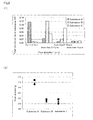
- so obtained substances had various fine pores in pore diameters (r), and the total volume (v) by each group classified by pore diameter, as shown in Fig. 2(1)
- the total volume (v) of each substance were adjusted to be more than 0ml and less than or equal to 0.17ml.
- the content of the micro fine pores of 2 ⁇ m or less diameters was 74vol.% in the total volume thereof.
- the content of the micro fine pores of 2 ⁇ m or less diameters was 5vol.% in the total volume thereof.
- the content of the micro fine pores of 2 ⁇ m or less diameters was 4vol.% in the total volume thereof.
- Slurry to be coated or deposited contained supports such as aluminum oxide with cerium oxide and zirconium oxide, the sum of which was 45wt.%, and an inorganic binder at 2wt.%. That is, the total amount was 47wt.%. At first, the slurry was poured into the cells 3 from the axially upper end surface thereof, and the excess amount of slurry was removed therefrom, and then the slurry was dried and burned. These operations were made on each substrate under the same conditions.
- the coat amounts (g) on the substances were calculated from the difference in its weight before and after the coating onto the substances. As can be seen from Fig. 2(2) , the coat amount onto the substance A was the greatest. The cost amounts onto the other two substrates were substantially decreased and the there are substantially no difference therebetween.
- the cordierite honeycomb structures 1 were produced conventionally by forming and burning as substances.
- the thickness of the cell wall was adjusted to 0.05mm (2mil) and the density of the cells was adjusted to 900cell/in 2 , which corresponds to substances employed presently for catalyst converter.
- These substances were treated differently in their maximum burning temperature of burning from 1390°C to 1450°C.
- so obtained substances were different with each other in the total volume of the micro fine pores.
- the fine pores were all made at 2 ⁇ m or less diameters (r). Two kinds of slurries (1) and (2) were prepared.
- the slurry (1) contained a support such as aluminum oxide with cerium oxide and zirconium oxide, the sum of which is 45wt.%, and inorganic binder at 2wt.%. The total amount was 47wt.%.
- the slurry (2) contained a support such as aluminum oxide at 42 wt.%, and inorganic binder at 2wt.%. The total amount was 44wt.%.
- the slurry was poured into the cells 3 from the axially upper end surface thereof, and the excess amount of slurry was removed therefrom, and then the slurry was dried and burned. These operations were made on each substance under the same conditions.
- the relationship between the total volume of the micro fine pores per 1g of substance and the coat amount is illustrated in Fig. 3 with respect to the slurry (1).
- the relationship between the total volume of the micro fine pores per 1g of substance and the coat amount is illustrated in Fig. 4 with respect to the slurry (2).
- the coat amount (g) onto the substance was calculated from the difference in its weight before and after the coating.
- the results obtained on the slurries (1) and (2) were seen in the plots as shown in Figs. 3 and 4 , respectively. Under the regression analysis on the obtained data, it was found that there is a positive correlation between the total volume of the micro fine pores per 1g of the substance and the coat amount.
- the linear regression lines were also obtained as shown in Figs. 3 and 4 .
- the coat amount of the slurry on the cell walls is enhanced by increasing the total volume (v) of the micro fine pores of 2 ⁇ m or less diameters, and the coat amount of the slurry is reduced by decreasing the total volume (v) of the fine pores of 2 ⁇ m or less diameters.
- the coat amount of the slurry is adjustable easily as desired.
- the deposit of solids in the slurry can be enhanced merely by adjusting the size of the fine pores distributed in the structure.
- the adjustment of the size of the fine pores can be effected by controlling the temperature of burning operation on the structure and the like, so that no further facilities are therefor required.
- the coat amount of the slurry onto the structure (namely, onto the cell walls) can also be adjusted by controlling the number of micro fine pores and/or the total volume thereof. This is because the coat amount of the slurry onto the structure depends strongly on the micro fine pores of 2 ⁇ m or less diameters. Recently, the thickness of the cell walls become reduced and the density of the cell become increased more and more, so that the cell clogging is more likely to occur.
Landscapes
- Chemical & Material Sciences (AREA)
- Engineering & Computer Science (AREA)
- Ceramic Engineering (AREA)
- Materials Engineering (AREA)
- Organic Chemistry (AREA)
- Structural Engineering (AREA)
- Chemical Kinetics & Catalysis (AREA)
- Inorganic Chemistry (AREA)
- Manufacturing & Machinery (AREA)
- Catalysts (AREA)
- Exhaust Gas Treatment By Means Of Catalyst (AREA)
Abstract
With the recent yearly increase in cell density, use of the same slurry as a conventional one for forcibly depositing a solid, e.g., alumina for supporting, on the surface of cell walls has come to arouse a trouble that the resultant coat layer is thick and cell clogging is more apt to occur. When a slurry whose viscosity has been reduced by reducing the binder amount is used, the slurry which has flowed into cells is discharged without leaving a solid adherent to the surface of the cell walls. Namely, it is difficult to secure a desired solid deposition amount. A honeycomb structure (1) for slurry coating is provided which is made of a porous object, wherein the surface (5) of cell walls formed in the structure has fine pores (7) dispersedly formed therein and having a pore diameter (r) of 2 µm or smaller. Preferably, the total volume (v) of the fine pores (7) is 0-0.17 ml, excluding 0 ml, per g of the structure.
Description
- The present invention relates to a honeycomb structure including cells therein, over which slurry is to be coated, and more particularly a honeycomb structure to be used preferably as a substance for catalysis for converting exhaust gas.
- Structures as substances for catalysis for converting exhaust gas are typically formed of ceramic materials. In terms of reduction in pressure loss and thermal capacity to provide premature activation of catalyst, recently, reduction in thickness of cell walls has been requested. The thicknesses of the cell walls were in '80th, amount to around 0.15 mm (6mil). The thickness of the cell walls, however, has been reduced nowadays to around 0.05mm (2mil).
On the other hand, the thickness reduction of the cell walls deteriorates the mechanical strength of the structures. This point has been compensated for by reducing the porosity of the structure to heighten the density. In the dense structure, the surface area of each cell is decreased, whereby it becomes difficult to deposit solids as catalyst carrier on the substances. This point has been compensated for by increasing the viscosity of the slurry, lowering the drawing speed of the slurry when flowing the slurry into the cells, lowering the blowing off speed of excess amount of the slurry from the cells, and so on. - Cross-reference: Japanese Laid-open public disclosure
2005-279436 - In recent years, with strengthen of exhaust gas controls, more and more improved converting function is required, so that the cell density of the structure has been increased year by year to 400cells/in2, 600cells/in2, and 900cells/in2. Accordingly, if conventional slurries are used, forcibly depositing a desired amount of solids as a support, e.g., alumina provides use of a large amount of slurry, thus thickening a resultant coat layer. Thickening the coat layer is more likely to occur cell clogging. Especially, as catalyst for automotive exhaust gas conversion, the slurry includes precious metals so that economic disadvantages become substantially high, if the cell clogging occurs.
In order to reduce the thickness of the coat layer, many countermeasures had been taken. There are countermeasures such as reducing the binder content in the slurry, reducing the solid content in the slurry, and/or adjusting the pH of the slurry to lower the viscosity thereof. However, if such countermeasures are taken, solids such as alumina become apt to settle in the slurry. Accordingly, it is required to stir the slurry always before coating. This leads to the additional expense on the management of the slurry. Further, when delivering the slurry through the cells, namely coating the slurry on the cells, the solids are apt to be discharged without being left and deposited on the surface of the cell wall. Therefore, it becomes difficult to deposit the solid to a desired amount. - In order to solve the above-mentioned problems, it is an object of the invention to provide a honeycomb structure, which is superior in its properties to be coated by slurry.
- The present inventors had noted relationship between the size of fine pores formed in the cell wall and the being coated properties, and repeated trial and error. As a result, the inventors has successfully found that micro fine pores having diameters of 2µm(micrometer) or less are closely related to the being coated properties. That is to say, if micro fine pores having diameters 2µm or less are formed and dispersed in the cell wall surface, larger amounts of slurry is coated on the cell walls by one coating operation. Based on this finding, there is provided a present invention of a honeycomb structure.
The honeycomb structure of the present invention is not intended to be limited to substances for catalytic converter for converting exhaust gas, but also may be also applied to other applications, provided that some slurry is coated. - In accordance with the present invention, there is provided a first aspect of a honeycomb structure for slurry coating as claimed in
claim 1, wherein the structure has a porous body of many cells, each cell wall having a plurality of micro fine pores with diameters of 2µm or less formed and dispersed in the cell wall surface. - According to a second aspect, there is provided the honeycomb structure for slurry coating as recited in the first aspect, wherein the total volume of the micro fine pores falls within the range of more than 0ml and less than or equal to 0.17ml per 1g of the structure.
- According to a third aspect, there is provided the honeycomb structure for slurry coating as claimed in
claim - According to the present invention, there is provided a honeycomb structure which is superior in its properties to be coated by slurry.
-
-
Fig. 1 shows a honeycomb structure of an embodiment in accordance with the present invention, in whichFig. 1(1) is a perspective view of the whole honeycomb structure, andFig. 1(2) is an enlarged cross-sectional view of the cell wall of the honeycomb structure. -
Fig. 2 explains example 1, in whichFig. 2(1) is a graph showing the relationship between the diameters and the total volume of fine pores on each substance, andFig. 2(2) is a graph showing the coat amount of slurry applied onto each substrate. -
Fig. 3 explains example 2, and is a graph showing the relationship between the total volume of micro fine pores and the coat amount of slurry. -
Fig. 4 explains example 2, and is a graph showing the relationship between the total volume of micro fine pores and the coat amount of slurry. -
- 1
- honeycomb structure
- 3
- cell
- 5
- cell wall
- 7
- micro fine pores
- r
- pore diameter
- v
- total volume
- The present invention will now be described with reference to the embodiment as shown in
Fig. 1 .
Thehoneycomb structure 1 of the present invention has a porous body of many cells. There are no limitations on the porous body inasmuch as micro fine pores of 2µm or less diameters can be formed in the cell wall. Thehoneycomb structure 1 may be made suitably of ceramics such as cordierite. - Although on configuration of the
honeycomb structure 1, there are no substantial limitations, the following description will be made with reference to the honeycomb structure of cylindrical configuration as shown inFig. 1(1) . Such configuration ones are used generally in catalytic converter for converting automotive exhaust gas. Thehoneycomb structure 1 has a plurality ofcells 3 formed therein. Thecells 3 are separated bycell walls 5. Thecells 3 serve as gas passages, extending longitudinally through both end faces of the structure.
A plurality of open fine pores is formed in the surfaces of eachcell wall 5, as shown inFig. 1(2) . It is characterized in that thehoneycomb structure 1 has microfine pores 7 of 2µm or less diameters (=pore diameter (r)) formed and dispersed in the cell wall surface. That is to say, thehoneycomb structure 1 has special micro fine pores among the open fine pores.
In thehoneycomb structure 1, a large amount of slurry is coated on thecell walls 5 only by one coating operation. This is because the microfine pores 7 distributed in the surface of thecell wall 5 cell cause the slurry to be secured thereon. In this connection, slurries of lower viscosity may be used in the present invention, and so-called cell clogging phenomena caused by use of high viscosity slurry is prevented.
Further, in thehoneycomb structure 1, the microfine pores 7 are distributed substantially uniformly over the surface of thecell wall 5 so that the slurry can also be coated uniformly thereon. - It is preferable that the total volume (v) of the micro
fine pores 7 of 2µm or less diameters per 1g of thestructure 1 falls within the range of more than 0ml and less than or equal to 0.17ml. The value of the lower limit i.e. 0 (=zero) ml of this range of volume (v) can of course be excluded, since it means that there are present no microfine pores 7 in the structure. It is preferred to set the lower limit of the volume to 0.01ml, in order to efficiently enhance the properties to be coated by slurry. On the other hand, although there are no substantial limitations on the upper limit of the porosity, the upper limit of the total volume (v) of the micro fine pores 7 is preferably 0.17ml, and more preferably 0.14 ml, since the larger the total volume, the more the total coat amount deposited on thecell wall 5 and the cell clogging is more apt to occur. - The
cell walls 5 may further include fine pores larger than the micro fine pores 7, such as those of more than 2µm diameters.
However, in order to make control of the coat amount of slurry on thecell wall 5 easier, it is preferable that the percentage of the microfine pores 7 of 2µm or less diameters is formed and dispersed in thecell wall 5 at more than 75vol.% among the total pore volume, and more preferably more than 90vol.%. - The
honeycomb structure 1 of the present invention may be produced of known materials and through known methods of production, depending on pores to be formed within the cell wall 5 (i.e. the diameter of the pores and the total volume of the pores).
The microfine pores 7 are formed by mixing combustible with raw material which makes thehoneycomb structure 1, forming a honeycomb structure, burning the structure while burning off or volatizing the combustible to leave a plurality of voids, as micro fine pores. The micro fine pores may be desirably made by suitably selecting raw material, adjusting a maximum temperature of the burning operation, a duration period of the maximum temperature, and a rate of heating and cooling and the like. - There are no limitations on ingredients to be contained in the slurry. Accordingly, although slurries of well-known compositions may be used, there may be also used slurries containing reduced amounts of binders. That is, slurries of lower viscosities may be used, since enhanced is the being coated properties, or the deposit properties of the solids on the
cell wall 5 of thehoneycomb structure 1.
If there is used a slurry containing solids of binder and support at the wide range of 15 to 58 wt.%, the deposit amount of the solids is depend on the presence of the micro fine pores of 2µm or less diameters (r). - Further, there are also no limitations on method for delivering slurry into the
cells 3. The coating operation of thecell wall 5 by slurry may be made either by pouring the slurry from the axially upper end surface of thehoneycomb structure 1 or by pushing up the slurry from the bottom end surface and removing the excess amount of slurry by pushing down or blowing off the slurry from the structure upon sensing the overflow of the slurry from the upper end surface of the structure. - An embodiment of the present invention had been described hereinabove. Although the description above contains much detail, these should not be construed as limiting the scope of the invention but merely providing illustrations of any of the presently preferred embodiments of the invention.
- The
cordierite honeycomb structures 1 were produced by forming and burning, as three substances A, B, and C, respectively. In each substance, the thickness of the cell walls of was adjusted to 0.05mm (2mil) and the density of the cells was adjusted to 900cell/in2, which corresponds to substances employed presently for catalyst converter. These substances were treated differently in their maximum burning temperature of burning from 1390°C to 1450°C. Thus, so obtained substances had various fine pores in pore diameters (r), and the total volume (v) by each group classified by pore diameter, as shown inFig. 2(1)
For the convenience of comparison, the total volume (v) of each substance were adjusted to be more than 0ml and less than or equal to 0.17ml.
In the case of the substance A, the content of the micro fine pores of 2µm or less diameters was 74vol.% in the total volume thereof. In the case of the substance B, the content of the micro fine pores of 2µm or less diameters was 5vol.% in the total volume thereof. In the case of the substance C, the content of the micro fine pores of 2µm or less diameters was 4vol.% in the total volume thereof.
Slurry to be coated or deposited contained supports such as aluminum oxide with cerium oxide and zirconium oxide, the sum of which was 45wt.%, and an inorganic binder at 2wt.%. That is, the total amount was 47wt.%. At first, the slurry was poured into thecells 3 from the axially upper end surface thereof, and the excess amount of slurry was removed therefrom, and then the slurry was dried and burned. These operations were made on each substrate under the same conditions. - The coat amounts (g) on the substances were calculated from the difference in its weight before and after the coating onto the substances. As can be seen from
Fig. 2(2) , the coat amount onto the substance A was the greatest. The cost amounts onto the other two substrates were substantially decreased and the there are substantially no difference therebetween. - These results prove that the coat amount onto the substances depend substantially on the existence of the micro fine pores of 2µm or less diameters (r). In other words, a large amount of solids as a support can be coated or deposited onto the cell walls evenly and stably, even if the slurry of relatively lower viscosity is used in spite of relatively higher viscosity ones.
- The
cordierite honeycomb structures 1 were produced conventionally by forming and burning as substances. In each substance, the thickness of the cell wall was adjusted to 0.05mm (2mil) and the density of the cells was adjusted to 900cell/in2, which corresponds to substances employed presently for catalyst converter. These substances were treated differently in their maximum burning temperature of burning from 1390°C to 1450°C. Thus, so obtained substances were different with each other in the total volume of the micro fine pores.
For the convenience of comparison, on all of the substances, the fine pores were all made at 2µm or less diameters (r).
Two kinds of slurries (1) and (2) were prepared. The slurry (1) contained a support such as aluminum oxide with cerium oxide and zirconium oxide, the sum of which is 45wt.%, and inorganic binder at 2wt.%. The total amount was 47wt.%. The slurry (2) contained a support such as aluminum oxide at 42 wt.%, and inorganic binder at 2wt.%. The total amount was 44wt.%. At first, the slurry was poured into thecells 3 from the axially upper end surface thereof, and the excess amount of slurry was removed therefrom, and then the slurry was dried and burned. These operations were made on each substance under the same conditions. - The relationship between the total volume of the micro fine pores per 1g of substance and the coat amount is illustrated in
Fig. 3 with respect to the slurry (1). The relationship between the total volume of the micro fine pores per 1g of substance and the coat amount is illustrated inFig. 4 with respect to the slurry (2).
The coat amount (g) onto the substance was calculated from the difference in its weight before and after the coating. The results obtained on the slurries (1) and (2) were seen in the plots as shown inFigs. 3 and 4 , respectively. Under the regression analysis on the obtained data, it was found that there is a positive correlation between the total volume of the micro fine pores per 1g of the substance and the coat amount. Thus the linear regression lines were also obtained as shown inFigs. 3 and 4 . The coefficient of decision, square (R2) calculated from the coefficient of correlation (R), was as follows. In the case of the slurry (1), there was R2 =0.9763, and in the case of the slurry (2), there was R2 =0.9898. Both were closer to 1. This means that the strong correlation is present. - It might be understand that there is a strong positive correlation when the total volume (v) of the micro fine pores of 2µm or less diameters (r) is present within the range of more than 0ml and less than or equal to 0.17ml. In other words, the coat amount of the slurry on the cell walls is enhanced by increasing the total volume (v) of the micro fine pores of 2µm or less diameters, and the coat amount of the slurry is reduced by decreasing the total volume (v) of the fine pores of 2µm or less diameters. Thus the coat amount of the slurry is adjustable easily as desired.
- In the honeycomb structure of the present invention, the deposit of solids in the slurry can be enhanced merely by adjusting the size of the fine pores distributed in the structure. The adjustment of the size of the fine pores can be effected by controlling the temperature of burning operation on the structure and the like, so that no further facilities are therefor required. Further, the coat amount of the slurry onto the structure (namely, onto the cell walls) can also be adjusted by controlling the number of micro fine pores and/or the total volume thereof. This is because the coat amount of the slurry onto the structure depends strongly on the micro fine pores of 2µm or less diameters.
Recently, the thickness of the cell walls become reduced and the density of the cell become increased more and more, so that the cell clogging is more likely to occur. In the above mentioned honeycomb structure, a desired amount of solids can be deposited on the structure even if a slurry is used with the blinder being contained at relatively small amount, compared with the prior art ones. In this connection, the problem of the cell clogging leading to the economic loss can reliably be prevented, if the structure of the invention is used.
Claims (3)
- A honeycomb structure for slurry coating, wherein the structure has a porous body of many cells, each cell wall having a plurality of micro fine pores with diameters of 2µm or less formed and dispersed in the cell wall surface.
- The honeycomb structure for slurry coating as claimed in claim 1, wherein the total volume of the micro fine pores falls within the range of more than 0ml and less than or equal to 0.17ml per 1 g of the structure.
- The honeycomb structure for slurry coating as claimed in claim 1 or 2, wherein the structure is for use as a substance for catalysis for converting exhaust gas.
Applications Claiming Priority (2)
| Application Number | Priority Date | Filing Date | Title |
|---|---|---|---|
| JP2006192467A JP5232368B2 (en) | 2006-07-13 | 2006-07-13 | Honeycomb structure for slurry coating |
| PCT/JP2007/062859 WO2008007546A1 (en) | 2006-07-13 | 2007-06-27 | Honeycomb structure for slurry coating |
Publications (1)
| Publication Number | Publication Date |
|---|---|
| EP2042236A1 true EP2042236A1 (en) | 2009-04-01 |
Family
ID=38923110
Family Applications (1)
| Application Number | Title | Priority Date | Filing Date |
|---|---|---|---|
| EP07767662A Withdrawn EP2042236A1 (en) | 2006-07-13 | 2007-06-27 | Honeycomb structure for slurry coating |
Country Status (5)
| Country | Link |
|---|---|
| US (1) | US7854982B2 (en) |
| EP (1) | EP2042236A1 (en) |
| JP (1) | JP5232368B2 (en) |
| CN (1) | CN101400444B (en) |
| WO (1) | WO2008007546A1 (en) |
Families Citing this family (4)
| Publication number | Priority date | Publication date | Assignee | Title |
|---|---|---|---|---|
| JP5508453B2 (en) * | 2011-03-30 | 2014-05-28 | 日本碍子株式会社 | Honeycomb structure and honeycomb catalyst body |
| JP5867384B2 (en) * | 2012-12-26 | 2016-02-24 | 株式会社デンソー | Manufacturing method of honeycomb structure |
| US10126282B2 (en) | 2014-09-23 | 2018-11-13 | Deere & Company | Yield estimation |
| JP6633952B2 (en) * | 2016-03-28 | 2020-01-22 | 日本碍子株式会社 | Honeycomb structure |
Family Cites Families (11)
| Publication number | Priority date | Publication date | Assignee | Title |
|---|---|---|---|---|
| JPS606699B2 (en) * | 1977-07-08 | 1985-02-20 | 三井金属鉱業株式会社 | catalyst carrier |
| US4284675A (en) | 1977-01-26 | 1981-08-18 | Mitsui Mining & Smelting Co., Ltd. | Carriers for catalysts |
| JPH0669534B2 (en) * | 1987-02-12 | 1994-09-07 | 日本碍子株式会社 | Cordierite honeycomb structure |
| JP3354745B2 (en) * | 1995-05-11 | 2002-12-09 | 三菱重工業株式会社 | DeNOx catalyst |
| US6087261A (en) * | 1997-09-30 | 2000-07-11 | Fujitsu Limited | Method for production of semiconductor device |
| US6087281A (en) * | 1998-02-25 | 2000-07-11 | Corning Incorporated | Low CTE cordierite bodies with narrow pore size distribution and method of making same |
| JP2000001365A (en) * | 1998-04-16 | 2000-01-07 | Denso Corp | Honeycomb structure and manufacturing method thereof |
| DE19917081B4 (en) | 1998-04-16 | 2012-06-06 | Denso Corporation | Honeycomb structure and process for its preparation |
| JP3755738B2 (en) * | 2000-12-26 | 2006-03-15 | 日立金属株式会社 | Cordierite honeycomb structure |
| JP4470554B2 (en) | 2004-03-29 | 2010-06-02 | トヨタ自動車株式会社 | Method for producing exhaust gas purification catalyst |
| JP2007136357A (en) * | 2005-11-18 | 2007-06-07 | Toyota Motor Corp | Method for producing exhaust gas purification catalyst |
-
2006
- 2006-07-13 JP JP2006192467A patent/JP5232368B2/en not_active Expired - Fee Related
-
2007
- 2007-06-27 CN CN2007800089259A patent/CN101400444B/en not_active Expired - Fee Related
- 2007-06-27 EP EP07767662A patent/EP2042236A1/en not_active Withdrawn
- 2007-06-27 US US12/225,117 patent/US7854982B2/en active Active
- 2007-06-27 WO PCT/JP2007/062859 patent/WO2008007546A1/en not_active Ceased
Non-Patent Citations (1)
| Title |
|---|
| See references of WO2008007546A1 * |
Also Published As
| Publication number | Publication date |
|---|---|
| JP5232368B2 (en) | 2013-07-10 |
| US7854982B2 (en) | 2010-12-21 |
| WO2008007546A1 (en) | 2008-01-17 |
| JP2008018342A (en) | 2008-01-31 |
| CN101400444B (en) | 2013-03-27 |
| CN101400444A (en) | 2009-04-01 |
| US20100035752A1 (en) | 2010-02-11 |
Similar Documents
| Publication | Publication Date | Title |
|---|---|---|
| CN101679135B (en) | Method for preparing a porous inorganic coating on a porous support using certain pore fillers | |
| EP1598102B1 (en) | Ceramic honeycomb structure | |
| EP0278750B1 (en) | Cordierite honeycomb structural bodies | |
| US8038955B2 (en) | Catalyst supporting honeycomb and method of manufacturing the same | |
| JP5904646B2 (en) | Cellular ceramic article having coated channels and method of making the same | |
| EP1452511B1 (en) | Method for manufacturing a honeycomb structure body | |
| EP2502662B1 (en) | Honeycomb filter and manufacturing method of the same | |
| US6936561B2 (en) | Monolithic zeolite coated structures and a method of manufacture | |
| JP4548968B2 (en) | Ceramic support and ceramic catalyst body | |
| US5773103A (en) | Inorganic membranes using porous cordierite support | |
| CN1638864A (en) | Structured catalysts containing thick washcoats and methods of making | |
| JP2008510606A5 (en) | ||
| WO2001079138A1 (en) | Honeycomb structure and method for its manufacture | |
| JP2013542094A5 (en) | ||
| EP2519482B1 (en) | Method of making polymeric barrier coating to mitigate binder migration in a diesel particulate filter to reduce filter pressure drop and temperature gradients | |
| KR20130138186A (en) | Method for applying discriminating layer onto porous ceramic filters | |
| JP4001800B2 (en) | Method for manufacturing honeycomb catalyst carrier | |
| US7854982B2 (en) | Honeycomb structure for slurry coating | |
| JP2000225340A (en) | Honeycomb structure | |
| Boettge et al. | Functionalization of open-celled foams by homogeneous slurry based coatings | |
| US20050261127A1 (en) | Catalyst carrier and catalyst body | |
| JP4365839B2 (en) | SiC bonding material | |
| SE507254C2 (en) | Catalysts for purifying gases or liquids | |
| EP1340542A1 (en) | Monolithic zeolite coated structures and a method of manufacture |
Legal Events
| Date | Code | Title | Description |
|---|---|---|---|
| PUAI | Public reference made under article 153(3) epc to a published international application that has entered the european phase |
Free format text: ORIGINAL CODE: 0009012 |
|
| 17P | Request for examination filed |
Effective date: 20080929 |
|
| AK | Designated contracting states |
Kind code of ref document: A1 Designated state(s): AT BE BG CH CY CZ DE DK EE ES FI FR GB GR HU IE IS IT LI LT LU LV MC MT NL PL PT RO SE SI SK TR |
|
| AX | Request for extension of the european patent |
Extension state: AL BA HR MK RS |
|
| DAX | Request for extension of the european patent (deleted) | ||
| RBV | Designated contracting states (corrected) |
Designated state(s): DE FR GB |
|
| STAA | Information on the status of an ep patent application or granted ep patent |
Free format text: STATUS: THE APPLICATION HAS BEEN WITHDRAWN |
|
| 18W | Application withdrawn |
Effective date: 20121025 |