EP2042205A2 - Syringe with cap and cap removal device - Google Patents
Syringe with cap and cap removal device Download PDFInfo
- Publication number
- EP2042205A2 EP2042205A2 EP08016963A EP08016963A EP2042205A2 EP 2042205 A2 EP2042205 A2 EP 2042205A2 EP 08016963 A EP08016963 A EP 08016963A EP 08016963 A EP08016963 A EP 08016963A EP 2042205 A2 EP2042205 A2 EP 2042205A2
- Authority
- EP
- European Patent Office
- Prior art keywords
- cap
- substance delivery
- elongated member
- delivery device
- substance
- Prior art date
- Legal status (The legal status is an assumption and is not a legal conclusion. Google has not performed a legal analysis and makes no representation as to the accuracy of the status listed.)
- Granted
Links
Images




Classifications
-
- A—HUMAN NECESSITIES
- A61—MEDICAL OR VETERINARY SCIENCE; HYGIENE
- A61M—DEVICES FOR INTRODUCING MEDIA INTO, OR ONTO, THE BODY; DEVICES FOR TRANSDUCING BODY MEDIA OR FOR TAKING MEDIA FROM THE BODY; DEVICES FOR PRODUCING OR ENDING SLEEP OR STUPOR
- A61M5/00—Devices for bringing media into the body in a subcutaneous, intra-vascular or intramuscular way; Accessories therefor, e.g. filling or cleaning devices, arm-rests
- A61M5/178—Syringes
-
- A—HUMAN NECESSITIES
- A61—MEDICAL OR VETERINARY SCIENCE; HYGIENE
- A61D—VETERINARY INSTRUMENTS, IMPLEMENTS, TOOLS, OR METHODS
- A61D1/00—Surgical instruments for veterinary use
- A61D1/02—Trocars or cannulas for teats; Vaccination appliances
-
- A—HUMAN NECESSITIES
- A61—MEDICAL OR VETERINARY SCIENCE; HYGIENE
- A61D—VETERINARY INSTRUMENTS, IMPLEMENTS, TOOLS, OR METHODS
- A61D7/00—Devices or methods for introducing solid, liquid, or gaseous remedies or other materials into or onto the bodies of animals
-
- A—HUMAN NECESSITIES
- A61—MEDICAL OR VETERINARY SCIENCE; HYGIENE
- A61M—DEVICES FOR INTRODUCING MEDIA INTO, OR ONTO, THE BODY; DEVICES FOR TRANSDUCING BODY MEDIA OR FOR TAKING MEDIA FROM THE BODY; DEVICES FOR PRODUCING OR ENDING SLEEP OR STUPOR
- A61M5/00—Devices for bringing media into the body in a subcutaneous, intra-vascular or intramuscular way; Accessories therefor, e.g. filling or cleaning devices, arm-rests
- A61M5/178—Syringes
- A61M5/31—Details
- A61M2005/3103—Leak prevention means for distal end of syringes, i.e. syringe end for mounting a needle
- A61M2005/3104—Caps for syringes without needle
-
- A—HUMAN NECESSITIES
- A61—MEDICAL OR VETERINARY SCIENCE; HYGIENE
- A61M—DEVICES FOR INTRODUCING MEDIA INTO, OR ONTO, THE BODY; DEVICES FOR TRANSDUCING BODY MEDIA OR FOR TAKING MEDIA FROM THE BODY; DEVICES FOR PRODUCING OR ENDING SLEEP OR STUPOR
- A61M5/00—Devices for bringing media into the body in a subcutaneous, intra-vascular or intramuscular way; Accessories therefor, e.g. filling or cleaning devices, arm-rests
- A61M5/178—Syringes
- A61M5/31—Details
- A61M5/32—Needles; Details of needles pertaining to their connection with syringe or hub; Accessories for bringing the needle into, or holding the needle on, the body; Devices for protection of needles
- A61M5/3205—Apparatus for removing or disposing of used needles or syringes, e.g. containers; Means for protection against accidental injuries from used needles
- A61M5/321—Means for protection against accidental injuries by used needles
- A61M5/3213—Caps placed axially onto the needle, e.g. equipped with finger protection guards
- A61M2005/3215—Tools enabling the cap placement
-
- A—HUMAN NECESSITIES
- A61—MEDICAL OR VETERINARY SCIENCE; HYGIENE
- A61M—DEVICES FOR INTRODUCING MEDIA INTO, OR ONTO, THE BODY; DEVICES FOR TRANSDUCING BODY MEDIA OR FOR TAKING MEDIA FROM THE BODY; DEVICES FOR PRODUCING OR ENDING SLEEP OR STUPOR
- A61M2209/00—Ancillary equipment
- A61M2209/08—Supports for equipment
- A61M2209/088—Supports for equipment on the body
-
- A—HUMAN NECESSITIES
- A61—MEDICAL OR VETERINARY SCIENCE; HYGIENE
- A61M—DEVICES FOR INTRODUCING MEDIA INTO, OR ONTO, THE BODY; DEVICES FOR TRANSDUCING BODY MEDIA OR FOR TAKING MEDIA FROM THE BODY; DEVICES FOR PRODUCING OR ENDING SLEEP OR STUPOR
- A61M39/00—Tubes, tube connectors, tube couplings, valves, access sites or the like, specially adapted for medical use
- A61M39/20—Closure caps or plugs for connectors or open ends of tubes
-
- A—HUMAN NECESSITIES
- A61—MEDICAL OR VETERINARY SCIENCE; HYGIENE
- A61M—DEVICES FOR INTRODUCING MEDIA INTO, OR ONTO, THE BODY; DEVICES FOR TRANSDUCING BODY MEDIA OR FOR TAKING MEDIA FROM THE BODY; DEVICES FOR PRODUCING OR ENDING SLEEP OR STUPOR
- A61M5/00—Devices for bringing media into the body in a subcutaneous, intra-vascular or intramuscular way; Accessories therefor, e.g. filling or cleaning devices, arm-rests
- A61M5/178—Syringes
- A61M5/31—Details
- A61M5/3129—Syringe barrels
- A61M5/3137—Specially designed finger grip means, e.g. for easy manipulation of the syringe rod
-
- A—HUMAN NECESSITIES
- A61—MEDICAL OR VETERINARY SCIENCE; HYGIENE
- A61M—DEVICES FOR INTRODUCING MEDIA INTO, OR ONTO, THE BODY; DEVICES FOR TRANSDUCING BODY MEDIA OR FOR TAKING MEDIA FROM THE BODY; DEVICES FOR PRODUCING OR ENDING SLEEP OR STUPOR
- A61M5/00—Devices for bringing media into the body in a subcutaneous, intra-vascular or intramuscular way; Accessories therefor, e.g. filling or cleaning devices, arm-rests
- A61M5/178—Syringes
- A61M5/31—Details
- A61M5/32—Needles; Details of needles pertaining to their connection with syringe or hub; Accessories for bringing the needle into, or holding the needle on, the body; Devices for protection of needles
- A61M5/3202—Devices for protection of the needle before use, e.g. caps
- A61M5/3204—Needle cap remover, i.e. devices to dislodge protection cover from needle or needle hub, e.g. deshielding devices
Definitions
- This invention relates to substance delivery devices and/or caps, particularly but not necessarily solely for use in veterinary applications.
- Syringes for injecting substances are well known. In general they consist of a barrel with a tip for dispensing a substance, or a connector suitable for receiving a needle, located at one end, and a plunger which contacts and seals with the interior surface of the barrel at the other end. Finger grips extend radially from the surface of the barrel at the end of the barrel which receives the plunger. The plunger is actuated by the thumb pressing against the end of the plunger. When fully actuated the end of the plunger and the finger grips are adjacent one another.
- syringe To provide controlled operation of a syringe during the dispensing procedure the syringe must be kept stable.
- stable is meant having minimal or no unwanted movement during the dispensing procedure.
- syringes used in the veterinary field for the intramammary application of treatments to prevent or control mastitis, for example in dairy cows.
- These syringes typically contain an antibiotic paste or gel.
- the veterinarian or farmer typically removes the cap from the syringe to expose a narrow tip that can vary in length from approximately 5 mm to 15 mm.
- the tip of the syringe is inserted into the teat opening.
- the plunger of the syringe is depressed with the thumb, finger or base of hand. When the contents of the syringe have been fully dispensed the tip is withdrawn and the syringe discarded.
- Prior art syringe arrangements do not allow for controlled operation of a syringe during the dispensing procedure, due to the relative positions of the finger grips and the end of the plunger when the syringe is fully actuated. As they are adjacent one another, the dispensing end of the barrel (which may or may not be fitted with a needle) is unsupported during the operation of the syringe, leaving the syringe unstable. If the syringe is unstable, it is difficult to obtain and maintain the correct injection site and this may cause discomfort to the recipient of the injection, together with the problems mentioned above.
- Keeping a syringe stable also assists the user in injecting the correct amount of the substance.
- prior art syringes are not ideal for dispensing substances such as viscous pastes and the like. This is because the thumb acting on the plunger has to provide sufficient force to move the plunger down towards the dispensing end of the barrel; an operation which can be inefficient and uncomfortable.
- Syringe caps which are currently in use are generally designed to be pulled or pushed or severed off the tip of the syringe prior to use. Accordingly, they can be difficult and tiresome to remove, particularly when using syringes repeatedly during farming operations. Usually they are pushed off with the thumb prior to use, which can cause damage to the syringe tip (bending or breakage) and can also present a contamination risk as the user's thumb or fingers may come into contact with the syringe tip during removal.
- a substance delivery device may include an elongated member adapted to interface with a body of the substance delivery device.
- Substance delivery devices may include, but are not limited to pumps, syringes, and/or any device currently known or yet to be discovered in the art.
- a body may include, but is not limited to a barrel, a tube, and/or any device currently known or yet to be discovered in the art.
- An elongated member may include, but is not limited to a plunger, a piston, and/or any device currently known or yet to be discovered in the art.
- the body may define a conduit therethrough. One or more openings may be disposed at the dispensing end of the body.
- the substance delivery device may include a gripping section which allows a user to grip the body with one or more digits of a user's hand.
- the gripping section may be positioned at any point along the length of the body. Some embodiments may be configured to maintain a predetermined separation distance between the gripping section and the rear end of the elongated member. Alternatively, some embodiments may be configured to maintain a separation distance between an end of the body and an end of the elongated member. Additionally, the body of the substance delivery device may have a preselected overall length.
- the elongated member may include a seal assembly.
- the elongated member may be adapted to be reciprocated through a predefined stroke length to move the seal assembly through the conduit within the body.
- the seal assembly may be moved from a fully retracted position to a fully depressed position to drive a substance present in the body out an opening positioned in the dispensing end of the body.
- the elongated member may be moved by applying pressure to an engaging member disposed at a rear end of the engaging member. Pressure may be applied to the engaging member with any surface, including but not limited to a digit or heel of the user's hands.
- the elongated member has a length that is substantially 110% or greater than the preselected overall length of the body.
- the engaging member may extend beyond an end of the body a predetermined distance when the elongated member is in the fully depressed position.
- the elongated member has a length that is greater than about 120% of the preselected overall length of the body. In some embodiments, the length of the elongated member may be greater than about 130%, 150%, 170%, 190%, 210%, 230%, 250%, 270% or 290% of the preselected overall length of the body.
- a portion of the elongated member proximate the engaging member is enlarged with respect to the rest of the elongated member for increased stability during use.
- the elongated member may have a flared end or a tapered outer periphery such that the diameter of the elongated member increases along the length of the elongated member towards the engaging member.
- the engaging member has a larger diameter than the rest of the elongated member for ease of use.
- the engaging member may be slightly concaved to accommodate application of pressure by the user comfortably during use.
- the invention may include a substance delivery device having a dispensing end and a rear end located opposite the dispensing end.
- the substance delivery device may include a body defining a conduit.
- the body may include openings disposed at the dispensing end of the substance delivery device and a gripping section which allows a user to grip the body. For example, the user may grip the body of the substance delivery device with one or more digits of a user's hand.
- the substance delivery device may include an elongated member having a seal assembly.
- the elongated member may be adapted to be reciprocated through a predefined stroke length to move the seal assembly through the conduit in the body.
- the elongated member may move from a fully retracted position to a fully depressed position. This movement may drive a substance when present in the body out of the body through the opening.
- the elongated member may have an engaging member at the rear end of the substance delivery device. A user may apply pressure to the engaging in order to reciprocate the elongated member.
- the engaging member and the gripping section are spaced from one another by a predetermined separation distance.
- some embodiments may be configured to maintain a separation distance between an end of the body and an end of the elongated member when the elongated member is in the fully depressed position.
- the separation distance is at least 50% of the predefined stroke length.
- Some embodiments include a separation distance that is, for example, greater than about 60%, 80%, 100%, 150%, 200% or 250% of the predefined stroke length.
- the separation distance is at least 2 cm.
- the separation distance may be, for example, greater than about 3 cm, 4 cm, 5 cm, 6 cm, 7 cm, 8 cm, 9 cm or 10 cm.
- the elongated member has a length that is at least 120% of the predefined stroke length.
- the length of the elongated member may be even greater.
- some embodiments may include an elongated member having a length that is greater than about 150%, 200%, 250%, 300%, 350% or 400% of the predefined stroke length.
- the engaging member when the elongated member is in the fully depressed position, the engaging member is disposed outward from the body. Thus, the engaging member may be positioned such that the engaging member extends beyond the gripping section by a predetermined separation distance.
- the substance delivery device includes a cap, which is adapted to removably couple to the body to protect the opening when not in use.
- a retaining assembly may be disposed on the cap and/or the body.
- An embodiment may include a cap adapted to removably couple to a container having an opening to protect the opening when not in use.
- a retaining assembly may be disposed on the cap and/or the body.
- the cap may include a receiving portion which receives at least a portion of the container therein in an insertion direction.
- the receiving portion may have a retaining assembly adapted to removably grip the container when present in the receiving portion with a retaining force adapted to removably retain the cap to the container.
- a leveragable portion may allow the cap to be removed from the container.
- the leveragable portion may have any geometry.
- a leveragable portion may include a shape protruding from the cap body to allow for leverage applied there against allowing for the removal of the cap from the container.
- the leveragable portion may include an outwardly contoured portion.
- the leveragable portion may include a frusto-conical shape in a side view.
- the leveragable portion may include a disc shaped member in a side view which can be located at a proximal end or distal end of the cap.
- the container is a substance delivery device and the cap has a top portion adapted to provide a stopper to prevent the tip of the substance delivery device from protruding there from.
- the top portion may be enclosed.
- the invention may include a cap removal device adapted to remove a cap from a container.
- a cap removal device may include a support portion adapted to be supported and to support a cantilever portion.
- a cantilever portion may be adapted to allow the cap to be removed from the container.
- the cantilever portion in combination with the support portion may form a first receiving recess.
- Some embodiments include a cantilever portion having two prongs forming a second recess therebetween. In such embodiments, when the leveragable portion of the cap is inserted in the first receiving recess and the hollow container receiving portion is inserted in the second recess, the cap can be removed from the container.
- the support portion may be supported by means of a band member adapted to be attached to a wrist, belt, structural element including, but not limited to a wall, a beam, a fence post, a door, a gate and/or any other object.
- the support portion may be adapted to be hung from an upstand or another structural element.
- Substance delivery device 10 may include body 12 and elongated member 14. Elongated member 14 may be positioned within body 12 such that dispensing end 16 of the body and rear end 18 of the elongated member are located opposite ends of the substance delivery device.
- Body 12 may include opening 20 at dispensing end 16 of substance delivery device 10.
- multiple openings may be disposed at the end of the substance delivery device.
- some embodiments may include one or more openings proximate dispensing end 16. Openings may be utilized for dispensing substances including but not limited to medicines.
- fluids including but not limited to viscous fluids such as pastes, gels may be dispensed using the substance delivery device.
- dispensing end 16 and/or opening 20 may include a needle.
- the dispensing end of the substance delivery device may include a needle, such as a hypodermic needle, a nozzle, and/or tubing to help direct the flow into and out of the body.
- body 12 includes gripping section 22 to allow a user to grip the body 12.
- gripping section 22 may be disposed on body 12 such that the fingers can support substance delivery device 10. Gripping section 22 may assist in obtaining the correct administration site and keeping the substance delivery device substantially stable during operation.
- gripping section 22 includes two protrusions.
- gripping section 22 may include a pair of opposing projections which extend at an angle from the surface of the body 12 as shown in Figure 3 . In some embodiments, the gripping section may extend substantially radially outward from the body of the substance delivery device.
- a gripping section may include a protrusion including, but not limited to a flange, rim, collar, and/or ring.
- the gripping section may be ergonomically designed to accommodate a user's digits and/or hands comfortably.
- a gripping section may have indentations or curves designed to conform with the shape of a hand or fingers. Use of fingers and/or a hand may support and guide the substance delivery device more effectively during operation due to the design of the substance delivery device. Accordingly, substances may be administered more accurately.
- having the ability to activate the substance delivery device by the heel of the hand may make the operation of the substance delivery device more comfortable to the user.
- Body 12 is adapted to receive elongated member 14 at end 24 of the body as shown in Figure 2 .
- Elongated member 14 depicted in Figure 4 may include engagement section 26, elongated section 28, and seal assembly 30.
- the diameter of elongated member 14 may vary along the length of the elongated member.
- the elongated member may have one or more sections which flare outward.
- the elongated member may have sections in which the cross-sectional diameter increases or decreases.
- the elongated member 14 has an engaging member 32 disposed at rear end 18 for engaging with a digit or heel of a user's hand as the user reciprocates the elongated member 14.
- the engaging member 32 may be enlarged so that it can be comfortably engaged with the heel of the user's hand during use.
- engaging member 32 may have a larger diameter than the rest of elongated member 14.
- Engaging member 32 may have geometry conducive to applying pressure.
- engaging member 32 may be slightly concaved to accommodate the user's thumb, fingers and/or hand comfortably during use.
- the engaging member does not have to be operated by the heel of a hand, as the thumb or another digit may be used instead.
- using the heel of the hand to depress the engaging member into the body towards the dispensing end may provide increased pressure, and is thus may make it easier and more comfortable to use.
- ease of use may be valuable where substance delivery devices are used repeatedly for an extended period of time.
- elongated member may include flared section 34 proximate the engaging member 32. Flared section 34 may provide increased stability during use.
- the diameter of the elongated member may vary along a length of the elongated member.
- an elongated member may have a flared end.
- elongated member 14 may have a tapered outer periphery such that the diameter of the elongated member increases along the length of the elongated member towards the engaging member.
- Figures 5 to 7 depict elongated member 14 positioned within body 12 in the fully depressed position.
- engaging member 32 and gripping section 22 may be spaced from one another by a predetermined separation distance ("B") (see Figure 5 ).
- B predetermined separation distance
- Figure 6 when fully depressed the configuration of the elongated member may maintain the predetermined separation distance ("B") between engaging member 32 and gripping section 22.
- Elongated member 14 may be positioned within conduit 36.
- a profile of the elongated member may substantially conform to a profile of the conduit.
- the profile of the elongated member may conform to portions of the conduit as depicted in Figure 6 .
- Conduit 36 communicates with opening 20.
- Figures 8-10 depict the elongated member positioned within the body.
- Figure 8 shows elongated member 32 positioned within body 12.
- elongated member 14 is adapted to be reciprocated through a predefined stroke length to move seal assembly 30 through the internal volume of body 12 from a fully retracted position (See Figure 9 ) to a fully depressed position (See Figure 6 ) to drive a substance when present in body 12 through opening 20.
- the predefined stroke length (“A") may be the distance elongated member 14 is moved from the fully retracted position as shown in Figure 9 to the fully depressed position as shown in Figure 6 .
- a stroke length may be defined as the distance indicated as "A” in Figure 9 .
- the stroke length may be predefined.
- a separation distance (“B") (as shown in Figure 5 ) may be equal to the value of at least 50% of a predefined stroke length ("A") (as shown in Figure 9 ).
- the separation distance ("B") may be even greater. In some embodiments, a separation distance may be greater than about 60%, 80%, 100%, 150%, 200% or 250% of the predefined stroke length. For example, the separation distance ("B") may be at least 2 cm. In alternate embodiments, the separation distance ("B") may be greater than that. For example, a separation distance ("B") may be greater than about 3 cm, 4 cm, 5 cm, 6 cm, 7 cm, 8 cm, 9 cm or 10 cm, depending on the desired overall dimensions of the substance delivery device. Alternately, in some embodiments the stroke length may vary.
- the separation distance ("B") (See Figure 5 ) may be achieved by providing elongated member 14 which has a length that is at least 120% of the predefined stroke length ("A") (See Figure 9 ).
- the length of the elongated member may be even greater, such as for example, greater than about 150%, 200%, 250%, 300%, 350% or 400% of the predefined stroke length. Accordingly, when the elongated member 14 is in the fully depressed position, the engaging member 32 is disposed outward from the body 12 to result in the engaging member 32 being disposed away from gripping section 22 by the predetermined separation distance ("B") as shown in Figure 5 .
- the elongated member may have a length that is substantially 110% or greater than the overall length of the body (which is preselected depending on the desired overall dimensions of the substance delivery device), such that the engaging member is disposed outward from an end of the body a predetermined distance when the elongated member is disposed in the fully depressed position.
- the elongated member has a length that is greater than about 120% of the preselected overall length of the body.
- the elongated member may have a length that is greater than about 130%, 150%, 170%, 190%, 210%, 230%, 250%, 270% or 290% of the preselected overall length of the body.
- the substance delivery device may include a cap.
- Caps may be designed to be easily removed prior to use such that removal of the cap does not cause damage and/or contamination to the dispensing end of the syringe. Caps may be removable, reusable and/or configured for single use.
- Figures 8 to 17 show various embodiments of caps 34 which may be used to protect the tips of substance delivery devices.
- Figure 12 shows the substance delivery device assembly comprising of elongated member 14, body 12 and cap 34 in an unassembled form. As shown in Figure 12 , each cap has proximal end 36 which will be positioned closest to body 12 and a distal end 38 positioned near the tip 40 when the cap is in place. In some embodiments, cap 34 may be configured to conform to profile of tip 40.
- Figure 13 shows the substance delivery device and cap as assembled and ready to use.
- Figure 14 depicts various views of cap 34.
- Figure 14a depicts a perspective view of cap 34.
- cap 34 may be contoured.
- Cap 34 has proximal end 36 closest to body 12 and includes a substantially hollow and substantially outwardly contoured, elongate structure.
- the elongate structure may define a length and have closed surface 42 at distal end 38.
- Figure 14b shows a cross-sectional view of the cap depicted in Figure 14d along line Z-Z'.
- Receiving portion 44 is coupled to top portion 46.
- each cap has a hollow receiving portion at the proximal end 36 for receiving the substance delivery device tip, and a top portion at the distal end 38 which may provide the means for enabling removal of the cap from the substance delivery device.
- the top portion may include a stop to prevent the tip of the substance delivery device from protruding therefrom.
- the stop can include any planar member with or without a recess or recesses.
- the stop may be curved therein. In one embodiment the stop may include a circumferential rim.
- Top portion 46 may include an end stop. End stops may include, but are not limited to various surface profiles such as flush, recessed, planar, projections and/or curved surfaces.
- end stops may include outer stopping surface 48 and/or inner stopping surface 50.
- inner stopping surface 50 is oriented substantially at right angles to the length of the substance delivery device and cap.
- inner stopping surface 50 may engage tip 40 of substance delivery device as shown in Figure 9 .
- a receiving portion of a cap may have an internal shape that allows the cap to couple to the substance delivery device.
- receiving portion 44 of cap 34 includes an inner portion shaped in a complementary shape to the substance delivery device outlet.
- the cap may be removably held by a retaining assembly (not shown) in place over the tip of the substance delivery device.
- a portion of the cap may removably grip a portion of the substance delivery device.
- a portion of the substance delivery device may be configured to grip a portion of the cap.
- the receiving portion of the cap may include a retaining assembly adapted to removably grip the substance delivery device when present in the receiving portion with a retaining force adapted to removably retain the cap to the substance delivery device.
- the retaining assembly may include any suitable configuration that allows for easy removal of the cap in use, yet sufficient cap retention when not in use.
- retaining assembly may include, but are not limited to fastening mechanisms, friction fits, interference fits, press fits, click in place type mechanisms, and/or any other mechanism currently known or yet to be discovered in the art.
- the cap may protect the substance delivery device and the contents of the substance delivery device from contamination. Further, the cap may protect the user of the substance delivery device. In use, when fitted to a substance delivery device, the proximal end of the cap may abut the body of the substance delivery device.
- leveragable portion 52 may be ergonomically shaped to enable a user to easily grip the cap and remove it.
- a leveragable portion may include, but are not limited flanges, rims, projections, rings, and/or collars.
- Figure 15 depicts a contoured cap having an ergonomic shape.
- the cap substantially conforms to the shape of the substance delivery device tip.
- cap 34 outwardly and inwardly substantially mirrors the shape of the substance delivery device tip.
- Figure 16 includes cap 34 having flared rim 54 at the proximal end 36.
- cap 34 has leveragable portion 52 at the distal end 38 which is disc-shaped to enable a user to easily grip the cap so it can be removed from the substance delivery device.
- the substance delivery device In use, if the substance delivery device is fitted with a cap as herein described, then the cap is first removed from the substance delivery device. The substance delivery device is then gripped using the fingers and the heel of the hand. The heel on the palm of a hand activates the engaging member by pushing it towards the dispensing end of the substance delivery device while the user simultaneously grips the flanges of the gripping section with their fingers.
- a user may simply grip the substance delivery device body and use their thumb to remove the cap, in a simple 'flicking' motion, as shown in Figure 18 .
- Figures 19 and 20 depict alternate embodiments utilizing removal devices 56.
- the cap removal devices comprise support portion 58 and a cantilever portion 60 having a space or a first receiving recess therebetween.
- Support portion 58 can be for example, a band or strap which can be worn around a user's wrist (as shown in Figure 19 ), or a band or sleeve which can be slidably attached to a user's belt (as shown in Figure 20 ).
- support portion 58 could be adapted to be attached to another object or an upstand or the like.
- the support portion may include, but is not limited to a hook shaped member and/or a member that is coupled using a fastener to a surface such as, a fence post, wall, framing, and/or any other convenient edge.
- Cantilever portion 60 is shaped in such a way that any cap may be inserted therein whilst still attached to a substance delivery device, to enable removal of the cap.
- cantilever portion 60 includes two spaced apart prongs 62, 62' with recess 64 therebetween.
- the prongs are spaced from support portion 58 to define a first receiving recess to allow the leveragable portion of cap 34 to be inserted behind the prongs and abut support portion 58 such that at least part of the body of the cap is accommodated in recess 64 between prongs 62, 62'.
- the method of removing a cap from a container such as a substance delivery device, utilizing a cap removal device as described herein includes supporting the support portion 58 of the cap removal device by attaching it to a wrist, belt, or other object, inserting the leveragable portion of the cap into the first receiving recess of the cap removal device such that the hollow receiving portion of the cap is accommodated by the second recess, pulling the container/cap assembly until the cap is removed from the container or substance delivery device.
- the substance delivery device may provide stability during the injection procedure and allow for controlled administration. When additional stability is provided, the injection procedure may be more effective and there may be less risk of contamination.
- activating the elongated member by engaging the heel of the hand with the engaging member may create more pressure and result in easier and less tiresome operation of the substance delivery device. This may be particularly useful when substance delivery devices are being used repeatedly for extended time periods.
- the substance delivery device may be designed to be comfortable and easy to use.
- a cap and cap removal device which requires less effort to remove the cap from a container or substance delivery device, and which results in less hand fatigue during repeated operations.
- Both the design of the cap and/or the use of the cap removal device provides for easier removal of the cap in cases where the cap is slippery. Also, there is less risk that the user's hands or fingers will contact the dispensing tip of the substance delivery device body or other container and cause contamination or damage (such as bending or breakage) to the dispensing tip.
- a substance delivery system for use in veterinary field may include any combination of the parts described herein.
- the cap is not restricted to a cap which fits on to a substance delivery device, as such a cap could be designed for other types of containers having openings which require protection.
- the measurements as exemplified herein are given by way of example only and are of course dependent on the overall dimensions of the substance delivery device and are therefore variable.
- the measurements are given to reflect a substance delivery device that could be reasonably used by a user with one hand.
- the substance delivery device may be used with the fingers and the heel of the hand simultaneously.
Landscapes
- Health & Medical Sciences (AREA)
- Veterinary Medicine (AREA)
- Life Sciences & Earth Sciences (AREA)
- General Health & Medical Sciences (AREA)
- Public Health (AREA)
- Animal Behavior & Ethology (AREA)
- Engineering & Computer Science (AREA)
- Wood Science & Technology (AREA)
- Zoology (AREA)
- Vascular Medicine (AREA)
- Surgery (AREA)
- Anesthesiology (AREA)
- Biomedical Technology (AREA)
- Heart & Thoracic Surgery (AREA)
- Hematology (AREA)
- Infusion, Injection, And Reservoir Apparatuses (AREA)
- Medical Preparation Storing Or Oral Administration Devices (AREA)
- External Artificial Organs (AREA)
Abstract
Description
- This application claims benefit of New Zealand provisional patent application Serial No.
562037 filed September 27, 2007 . - All documents cited or referenced herein ("herein cited documents"), and all documents cited or referenced in herein cited documents, together with any manufacturer's instructions, descriptions, product specifications, and product sheets for any products mentioned herein or in any document incorporated by reference herein, are hereby incorporated herein by reference, and may be employed in the practice of the invention.
- In addition, commonly assigned design patent applications of ROBERT WILLIAM LACHLAN HOLMES previously filed as "SYRINGE CAP" (
U.S. Application No. 29/305,650 ) and "SYRINGE CAP" (U.S. Application No. 29/305,651 ) are hereby incorporated by reference. - This invention relates to substance delivery devices and/or caps, particularly but not necessarily solely for use in veterinary applications.
- Syringes for injecting substances are well known. In general they consist of a barrel with a tip for dispensing a substance, or a connector suitable for receiving a needle, located at one end, and a plunger which contacts and seals with the interior surface of the barrel at the other end. Finger grips extend radially from the surface of the barrel at the end of the barrel which receives the plunger. The plunger is actuated by the thumb pressing against the end of the plunger. When fully actuated the end of the plunger and the finger grips are adjacent one another.
- To provide controlled operation of a syringe during the dispensing procedure the syringe must be kept stable. By "stable" is meant having minimal or no unwanted movement during the dispensing procedure.
- Of particular interest are syringes used in the veterinary field for the intramammary application of treatments to prevent or control mastitis, for example in dairy cows. These syringes typically contain an antibiotic paste or gel. To administer this material the veterinarian or farmer typically removes the cap from the syringe to expose a narrow tip that can vary in length from approximately 5 mm to 15 mm. While holding the teat of the cow in one hand and the syringe in the other, the tip of the syringe is inserted into the teat opening. The plunger of the syringe is depressed with the thumb, finger or base of hand. When the contents of the syringe have been fully dispensed the tip is withdrawn and the syringe discarded.
- Survey studies in New Zealand have shown that there are a number of methods employed by users to both remove the cap of the syringe and to hold the syringe and dispense the contents.
- It was found that: 23.5% of users gripped the cap in their teeth in order to remove it; 14.6% of users pushed the cap off with their thumb in a sideways movement; and 61 % of users held the syringe in one hand while pulling the cap off with the other. All users expressed frustration with existing syringe designs because due to the nature of the environment in which they are applied the caps are very slippery to grip. This makes them very difficult to remove.
- Users also expressed frustration with the difficulty with which syringes could be held during use. 85% of users held the syringe in what could be classified as the traditional manner with their fingers on the finger grips and thumb on the plunger. 10% of users held the syringe with their fingers on the finger grips and the base of the plunger in the palm of their hand. In the case of intramammary syringes where the cow may be moving around it is important that the syringe can be held firmly at all times. Another particular reason for this is that it is critical that no contamination or bacteria is introduced onto the tip of the syringe during the dispensing procedure. If the syringe is not able to be held firmly it may brush the outside of the udder or the cow's leg or other barrel part, thereby causing contamination of the syringe.
- Prior art syringe arrangements do not allow for controlled operation of a syringe during the dispensing procedure, due to the relative positions of the finger grips and the end of the plunger when the syringe is fully actuated. As they are adjacent one another, the dispensing end of the barrel (which may or may not be fitted with a needle) is unsupported during the operation of the syringe, leaving the syringe unstable. If the syringe is unstable, it is difficult to obtain and maintain the correct injection site and this may cause discomfort to the recipient of the injection, together with the problems mentioned above.
- Keeping a syringe stable also assists the user in injecting the correct amount of the substance.
- In addition, prior art syringes are not ideal for dispensing substances such as viscous pastes and the like. This is because the thumb acting on the plunger has to provide sufficient force to move the plunger down towards the dispensing end of the barrel; an operation which can be inefficient and uncomfortable.
- There is a need for a syringe that is more stable than prior art syringes during the injection procedure and which is efficient, comfortable and easy to use irrespective of the substance being administered.
- Syringe caps which are currently in use are generally designed to be pulled or pushed or severed off the tip of the syringe prior to use. Accordingly, they can be difficult and tiresome to remove, particularly when using syringes repeatedly during farming operations. Usually they are pushed off with the thumb prior to use, which can cause damage to the syringe tip (bending or breakage) and can also present a contamination risk as the user's thumb or fingers may come into contact with the syringe tip during removal.
- The discussion herein of the background to the invention is included to explain the context of the invention. This is not to be taken as an admission that any of the material referred to was published, known or part of the common general knowledge as of the priority date of any of the claims of the invention.
- In an embodiment, a substance delivery device may include an elongated member adapted to interface with a body of the substance delivery device. Substance delivery devices may include, but are not limited to pumps, syringes, and/or any device currently known or yet to be discovered in the art. A body may include, but is not limited to a barrel, a tube, and/or any device currently known or yet to be discovered in the art. An elongated member may include, but is not limited to a plunger, a piston, and/or any device currently known or yet to be discovered in the art.
- The body may define a conduit therethrough. One or more openings may be disposed at the dispensing end of the body. Further, the substance delivery device may include a gripping section which allows a user to grip the body with one or more digits of a user's hand. The gripping section may be positioned at any point along the length of the body. Some embodiments may be configured to maintain a predetermined separation distance between the gripping section and the rear end of the elongated member. Alternatively, some embodiments may be configured to maintain a separation distance between an end of the body and an end of the elongated member. Additionally, the body of the substance delivery device may have a preselected overall length.
- In an embodiment, the elongated member may include a seal assembly. The elongated member may be adapted to be reciprocated through a predefined stroke length to move the seal assembly through the conduit within the body. In some embodiments, the seal assembly may be moved from a fully retracted position to a fully depressed position to drive a substance present in the body out an opening positioned in the dispensing end of the body. The elongated member may be moved by applying pressure to an engaging member disposed at a rear end of the engaging member. Pressure may be applied to the engaging member with any surface, including but not limited to a digit or heel of the user's hands.
- In some embodiments, the elongated member has a length that is substantially 110% or greater than the preselected overall length of the body. Thus, the engaging member may extend beyond an end of the body a predetermined distance when the elongated member is in the fully depressed position.
- In an embodiment, the elongated member has a length that is greater than about 120% of the preselected overall length of the body. In some embodiments, the length of the elongated member may be greater than about 130%, 150%, 170%, 190%, 210%, 230%, 250%, 270% or 290% of the preselected overall length of the body.
- In an embodiment, a portion of the elongated member proximate the engaging member is enlarged with respect to the rest of the elongated member for increased stability during use. For example, the elongated member may have a flared end or a tapered outer periphery such that the diameter of the elongated member increases along the length of the elongated member towards the engaging member.
- In an embodiment, the engaging member has a larger diameter than the rest of the elongated member for ease of use. The engaging member may be slightly concaved to accommodate application of pressure by the user comfortably during use.
- In a further embodiment, the invention may include a substance delivery device having a dispensing end and a rear end located opposite the dispensing end. The substance delivery device may include a body defining a conduit. The body may include openings disposed at the dispensing end of the substance delivery device and a gripping section which allows a user to grip the body. For example, the user may grip the body of the substance delivery device with one or more digits of a user's hand.
- The substance delivery device may include an elongated member having a seal assembly. The elongated member may be adapted to be reciprocated through a predefined stroke length to move the seal assembly through the conduit in the body. The elongated member may move from a fully retracted position to a fully depressed position. This movement may drive a substance when present in the body out of the body through the opening. The elongated member may have an engaging member at the rear end of the substance delivery device. A user may apply pressure to the engaging in order to reciprocate the elongated member.
- In some embodiments, when the elongated member is in the fully depressed position, the engaging member and the gripping section are spaced from one another by a predetermined separation distance. Alternatively, some embodiments may be configured to maintain a separation distance between an end of the body and an end of the elongated member when the elongated member is in the fully depressed position.
- In an embodiment, the separation distance is at least 50% of the predefined stroke length. Some embodiments include a separation distance that is, for example, greater than about 60%, 80%, 100%, 150%, 200% or 250% of the predefined stroke length.
- In an embodiment, the separation distance is at least 2 cm. The separation distance may be, for example, greater than about 3 cm, 4 cm, 5 cm, 6 cm, 7 cm, 8 cm, 9 cm or 10 cm.
- In an embodiment, the elongated member has a length that is at least 120% of the predefined stroke length. The length of the elongated member may be even greater. For example, some embodiments may include an elongated member having a length that is greater than about 150%, 200%, 250%, 300%, 350% or 400% of the predefined stroke length. In some embodiments, when the elongated member is in the fully depressed position, the engaging member is disposed outward from the body. Thus, the engaging member may be positioned such that the engaging member extends beyond the gripping section by a predetermined separation distance.
- In an embodiment, the substance delivery device includes a cap, which is adapted to removably couple to the body to protect the opening when not in use. In some embodiments, a retaining assembly may be disposed on the cap and/or the body.
- An embodiment may include a cap adapted to removably couple to a container having an opening to protect the opening when not in use. In some embodiments, a retaining assembly may be disposed on the cap and/or the body.
- The cap may include a receiving portion which receives at least a portion of the container therein in an insertion direction. The receiving portion may have a retaining assembly adapted to removably grip the container when present in the receiving portion with a retaining force adapted to removably retain the cap to the container.
- Further, a leveragable portion may allow the cap to be removed from the container. The leveragable portion may have any geometry. For example, a leveragable portion may include a shape protruding from the cap body to allow for leverage applied there against allowing for the removal of the cap from the container. In some embodiments, the leveragable portion may include an outwardly contoured portion. Alternatively, the leveragable portion may include a frusto-conical shape in a side view. In an embodiment, the leveragable portion may include a disc shaped member in a side view which can be located at a proximal end or distal end of the cap.
- In an embodiment, the container is a substance delivery device and the cap has a top portion adapted to provide a stopper to prevent the tip of the substance delivery device from protruding there from. The top portion may be enclosed.
- In still a further aspect, the invention may include a cap removal device adapted to remove a cap from a container. A cap removal device may include a support portion adapted to be supported and to support a cantilever portion. A cantilever portion may be adapted to allow the cap to be removed from the container. In some embodiments, the cantilever portion in combination with the support portion may form a first receiving recess. Some embodiments include a cantilever portion having two prongs forming a second recess therebetween. In such embodiments, when the leveragable portion of the cap is inserted in the first receiving recess and the hollow container receiving portion is inserted in the second recess, the cap can be removed from the container.
- In some embodiments, the support portion may be supported by means of a band member adapted to be attached to a wrist, belt, structural element including, but not limited to a wall, a beam, a fence post, a door, a gate and/or any other object. Alternatively, the support portion may be adapted to be hung from an upstand or another structural element.
- Throughout the body of this description reference will be made to the accompanying drawings in which:
-
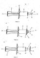
Figure 1 is an isometric view of the embodiment of the substance delivery device, -
Figure 2 is a perspective view of a substance delivery device body in accordance with an embodiment of the present invention, -
Figure 3 is a top view of the embodiment of the substance delivery device as shown inFigure 1 , -
Figure 4 is a perspective view of a substance delivery device elongated member in accordance with an embodiment of the present invention, -
Figure 5 is a front view of a substance delivery device in a fully depressed position in accordance with an embodiment of the present invention, -
Figure 6 is a cross-sectional view of the embodiment of the substance delivery device as shown inFigure 5 , along the line X-X', -
Figure 7 is a side view of the embodiment of the substance delivery device as shown inFigure 5 , -
Figure 8 is a front view of a substance delivery device (including a cap) in a fully retracted position in accordance with an embodiment of the present invention, -
Figure 9 is a cross-sectional view of the embodiment of the substance delivery device as shown inFigure 8 , along the line Y-Y', -
Figure 10 is a side view of the embodiment of the substance delivery device as shown inFigure 1 , -
Figure 11 is a perspective view of the embodiment of the substance delivery device shown inFigure 1 , -
Figure 12 is a perspective view of an unassembled cap and substance delivery device including the body and elongated member, -
Figure 13 is a perspective view of the cap, body and elongated member shown inFigure 13 as assembled, -
Figures 14a-e are a series of views of a cap including a cross-sectional view of the embodiment of the cap as shown inFigure 14a , along the line Z-Z', -
Figure 15 is a side view of a substance delivery device with a flared cap, -
Figure 16 is a side view of a substance delivery device with a cap having a frusto-conical shaped leveragable portion, -
Figure 17 is a side view of a substance delivery device with a cap having a leveragable portion with a disc-shaped end, -
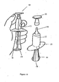
Figure 18 is a perspective view showing the cap being removed from the substance delivery device by a user, -
Figure 19 is a perspective view of an embodiment of a cap removal device adapted to be worn around a wrist of a user, and -
Figure 20 is a perspective view of a further embodiment of a cap removal device, adapted to be worn on a belt of a user. - The following description is given by way of illustration only and shall not be taken as being in any way limiting as to the spirit or scope of the invention. Referring to the drawings, like numerals designate corresponding parts where possible throughout the several figures.
- An embodiment of substance delivery device is depicted in
Figure 1 .Substance delivery device 10 may includebody 12 andelongated member 14.Elongated member 14 may be positioned withinbody 12 such that dispensingend 16 of the body andrear end 18 of the elongated member are located opposite ends of the substance delivery device. -
Body 12 may include opening 20 at dispensingend 16 ofsubstance delivery device 10. In some embodiments, multiple openings may be disposed at the end of the substance delivery device. Alternately, some embodiments may include one or more openings proximate dispensingend 16. Openings may be utilized for dispensing substances including but not limited to medicines. In some embodiments, fluids, including but not limited to viscous fluids such as pastes, gels may be dispensed using the substance delivery device. In some embodiments, dispensingend 16 and/oropening 20 may include a needle. In some embodiments, the dispensing end of the substance delivery device may include a needle, such as a hypodermic needle, a nozzle, and/or tubing to help direct the flow into and out of the body. - As shown in
Figure 2 ,body 12 includes grippingsection 22 to allow a user to grip thebody 12. For example, user may use one or more digits of user's hand. Grippingsection 22 may be disposed onbody 12 such that the fingers can supportsubstance delivery device 10. Grippingsection 22 may assist in obtaining the correct administration site and keeping the substance delivery device substantially stable during operation. In the embodiment shown inFigure 2 , grippingsection 22 includes two protrusions. In an embodiment, grippingsection 22 may include a pair of opposing projections which extend at an angle from the surface of thebody 12 as shown inFigure 3 . In some embodiments, the gripping section may extend substantially radially outward from the body of the substance delivery device. For example, a gripping section may include a protrusion including, but not limited to a flange, rim, collar, and/or ring. In some embodiments, the gripping section may be ergonomically designed to accommodate a user's digits and/or hands comfortably. For example, a gripping section may have indentations or curves designed to conform with the shape of a hand or fingers. Use of fingers and/or a hand may support and guide the substance delivery device more effectively during operation due to the design of the substance delivery device. Accordingly, substances may be administered more accurately. In some embodiments, having the ability to activate the substance delivery device by the heel of the hand, may make the operation of the substance delivery device more comfortable to the user. -
Body 12 is adapted to receiveelongated member 14 atend 24 of the body as shown inFigure 2 .Elongated member 14 depicted inFigure 4 may includeengagement section 26,elongated section 28, and sealassembly 30. As shown inFigures 3-10 , the diameter ofelongated member 14 may vary along the length of the elongated member. Thus, the elongated member may have one or more sections which flare outward. Alternately, the elongated member may have sections in which the cross-sectional diameter increases or decreases. - As shown in
Figure 4 , theelongated member 14 has an engagingmember 32 disposed atrear end 18 for engaging with a digit or heel of a user's hand as the user reciprocates theelongated member 14. In some embodiments, the engagingmember 32 may be enlarged so that it can be comfortably engaged with the heel of the user's hand during use. For example, engagingmember 32 may have a larger diameter than the rest ofelongated member 14. Engagingmember 32 may have geometry conducive to applying pressure. In some embodiments, engagingmember 32 may be slightly concaved to accommodate the user's thumb, fingers and/or hand comfortably during use. - It will be obvious to those skilled in the art that the engaging member does not have to be operated by the heel of a hand, as the thumb or another digit may be used instead. In some embodiments, using the heel of the hand to depress the engaging member into the body towards the dispensing end may provide increased pressure, and is thus may make it easier and more comfortable to use. In the case of farming operations, ease of use may be valuable where substance delivery devices are used repeatedly for an extended period of time.
- As shown in
Figure 4 , elongated member may include flaredsection 34 proximate the engagingmember 32. Flaredsection 34 may provide increased stability during use. In some embodiments, the diameter of the elongated member may vary along a length of the elongated member. Alternatively, an elongated member may have a flared end. In some embodiments, elongated member 14may have a tapered outer periphery such that the diameter of the elongated member increases along the length of the elongated member towards the engaging member. -
Figures 5 to 7 depictelongated member 14 positioned withinbody 12 in the fully depressed position. As shown inFigures 5 to 7 , engagingmember 32 andgripping section 22 may be spaced from one another by a predetermined separation distance ("B") (seeFigure 5 ). As shown in the cross-sectional depiction ofFigure 6 , when fully depressed the configuration of the elongated member may maintain the predetermined separation distance ("B") between engagingmember 32 andgripping section 22. -
Elongated member 14 may be positioned withinconduit 36. In some embodiments, a profile of the elongated member may substantially conform to a profile of the conduit. In alternate embodiments, the profile of the elongated member may conform to portions of the conduit as depicted inFigure 6 .Conduit 36 communicates withopening 20. -
Figures 8-10 depict the elongated member positioned within the body.Figure 8 showselongated member 32 positioned withinbody 12. - As shown in
Figure 6 andFigure 9 , elongatedmember 14 is adapted to be reciprocated through a predefined stroke length to moveseal assembly 30 through the internal volume ofbody 12 from a fully retracted position (SeeFigure 9 ) to a fully depressed position (SeeFigure 6 ) to drive a substance when present inbody 12 throughopening 20. The predefined stroke length ("A") (SeeFigure 9 ) may be the distance elongatedmember 14 is moved from the fully retracted position as shown inFigure 9 to the fully depressed position as shown inFigure 6 . - A stroke length may be defined as the distance indicated as "A" in
Figure 9 . In some embodiments, the stroke length may be predefined. In some embodiments, a separation distance ("B") (as shown inFigure 5 ) may be equal to the value of at least 50% of a predefined stroke length ("A") (as shown inFigure 9 ). - In an embodiment, the separation distance ("B") may be even greater. In some embodiments, a separation distance may be greater than about 60%, 80%, 100%, 150%, 200% or 250% of the predefined stroke length. For example, the separation distance ("B") may be at least 2 cm. In alternate embodiments, the separation distance ("B") may be greater than that. For example, a separation distance ("B") may be greater than about 3 cm, 4 cm, 5 cm, 6 cm, 7 cm, 8 cm, 9 cm or 10 cm, depending on the desired overall dimensions of the substance delivery device. Alternately, in some embodiments the stroke length may vary.
- In an embodiment, the separation distance ("B") (See
Figure 5 ) may be achieved by providingelongated member 14 which has a length that is at least 120% of the predefined stroke length ("A") (SeeFigure 9 ). In an embodiment, the length of the elongated member may be even greater, such as for example, greater than about 150%, 200%, 250%, 300%, 350% or 400% of the predefined stroke length. Accordingly, when theelongated member 14 is in the fully depressed position, the engagingmember 32 is disposed outward from thebody 12 to result in the engagingmember 32 being disposed away from grippingsection 22 by the predetermined separation distance ("B") as shown inFigure 5 . - Described in another way, the elongated member may have a length that is substantially 110% or greater than the overall length of the body (which is preselected depending on the desired overall dimensions of the substance delivery device), such that the engaging member is disposed outward from an end of the body a predetermined distance when the elongated member is disposed in the fully depressed position. In some embodiments, the elongated member has a length that is greater than about 120% of the preselected overall length of the body. For example, the elongated member may have a length that is greater than about 130%, 150%, 170%, 190%, 210%, 230%, 250%, 270% or 290% of the preselected overall length of the body.
- In some embodiments, the substance delivery device may include a cap. Caps may be designed to be easily removed prior to use such that removal of the cap does not cause damage and/or contamination to the dispensing end of the syringe. Caps may be removable, reusable and/or configured for single use.
-
Figures 8 to 17 show various embodiments ofcaps 34 which may be used to protect the tips of substance delivery devices.Figure 12 shows the substance delivery device assembly comprising ofelongated member 14,body 12 andcap 34 in an unassembled form. As shown inFigure 12 , each cap hasproximal end 36 which will be positioned closest tobody 12 and adistal end 38 positioned near thetip 40 when the cap is in place. In some embodiments,cap 34 may be configured to conform to profile oftip 40.Figure 13 shows the substance delivery device and cap as assembled and ready to use. -
Figure 14 depicts various views ofcap 34.Figure 14a depicts a perspective view ofcap 34. As shown inFigure 14a ,cap 34 may be contoured.Cap 34 hasproximal end 36 closest tobody 12 and includes a substantially hollow and substantially outwardly contoured, elongate structure. The elongate structure may define a length and have closed surface 42 atdistal end 38.Figure 14b shows a cross-sectional view of the cap depicted inFigure 14d along line Z-Z'. Receivingportion 44 is coupled totop portion 46. As shown inFigures 14b and 14e , each cap has a hollow receiving portion at theproximal end 36 for receiving the substance delivery device tip, and a top portion at thedistal end 38 which may provide the means for enabling removal of the cap from the substance delivery device. The top portion may include a stop to prevent the tip of the substance delivery device from protruding therefrom. The stop can include any planar member with or without a recess or recesses. The stop may be curved therein. In one embodiment the stop may include a circumferential rim.Top portion 46 may include an end stop. End stops may include, but are not limited to various surface profiles such as flush, recessed, planar, projections and/or curved surfaces. In addition, end stops may include outer stoppingsurface 48 and/or inner stoppingsurface 50. For example, as shown inFigure 14b inner stoppingsurface 50 is oriented substantially at right angles to the length of the substance delivery device and cap. In some embodiments, inner stoppingsurface 50 may engagetip 40 of substance delivery device as shown inFigure 9 . - A receiving portion of a cap may have an internal shape that allows the cap to couple to the substance delivery device. For example, as shown in
Figure 14b receiving portion 44 ofcap 34 includes an inner portion shaped in a complementary shape to the substance delivery device outlet. In some embodiments, the cap may be removably held by a retaining assembly (not shown) in place over the tip of the substance delivery device. - In some embodiments, a portion of the cap may removably grip a portion of the substance delivery device. Alternately, a portion of the substance delivery device may be configured to grip a portion of the cap. The receiving portion of the cap may include a retaining assembly adapted to removably grip the substance delivery device when present in the receiving portion with a retaining force adapted to removably retain the cap to the substance delivery device. The retaining assembly may include any suitable configuration that allows for easy removal of the cap in use, yet sufficient cap retention when not in use. For example, retaining assembly may include, but are not limited to fastening mechanisms, friction fits, interference fits, press fits, click in place type mechanisms, and/or any other mechanism currently known or yet to be discovered in the art.
- In an embodiment, the cap may protect the substance delivery device and the contents of the substance delivery device from contamination. Further, the cap may protect the user of the substance delivery device. In use, when fitted to a substance delivery device, the proximal end of the cap may abut the body of the substance delivery device.
-
Figures 15-17 show various embodiments ofcap 34 different profiles havingleveragable portion 52. In some embodiments,leveragable portion 52 may be ergonomically shaped to enable a user to easily grip the cap and remove it. In addition, a leveragable portion may include, but are not limited flanges, rims, projections, rings, and/or collars. -
Figure 15 depicts a contoured cap having an ergonomic shape. In addition, the cap substantially conforms to the shape of the substance delivery device tip. InFigure 16 ,cap 34 outwardly and inwardly substantially mirrors the shape of the substance delivery device tip.Figure 16 includescap 34 having flaredrim 54 at theproximal end 36. InFigure 17 ,cap 34 hasleveragable portion 52 at thedistal end 38 which is disc-shaped to enable a user to easily grip the cap so it can be removed from the substance delivery device. - In use, if the substance delivery device is fitted with a cap as herein described, then the cap is first removed from the substance delivery device. The substance delivery device is then gripped using the fingers and the heel of the hand. The heel on the palm of a hand activates the engaging member by pushing it towards the dispensing end of the substance delivery device while the user simultaneously grips the flanges of the gripping section with their fingers.
- In order to remove any of the caps described herein, a user may simply grip the substance delivery device body and use their thumb to remove the cap, in a simple 'flicking' motion, as shown in
Figure 18 . -
Figures 19 and20 depict alternate embodiments utilizingremoval devices 56. The cap removal devices comprisesupport portion 58 and acantilever portion 60 having a space or a first receiving recess therebetween.Support portion 58 can be for example, a band or strap which can be worn around a user's wrist (as shown inFigure 19 ), or a band or sleeve which can be slidably attached to a user's belt (as shown inFigure 20 ). Alternatively,support portion 58 could be adapted to be attached to another object or an upstand or the like. For example, the support portion may include, but is not limited to a hook shaped member and/or a member that is coupled using a fastener to a surface such as, a fence post, wall, framing, and/or any other convenient edge. -
Cantilever portion 60 is shaped in such a way that any cap may be inserted therein whilst still attached to a substance delivery device, to enable removal of the cap. As shown inFigure 20 ,cantilever portion 60 includes two spaced apart prongs 62, 62' withrecess 64 therebetween. The prongs are spaced fromsupport portion 58 to define a first receiving recess to allow the leveragable portion ofcap 34 to be inserted behind the prongs andabut support portion 58 such that at least part of the body of the cap is accommodated inrecess 64 betweenprongs 62, 62'. Once the leveragable portion of the cap is in this position the user only then needs to pull in the direction parallel to the length of the substance delivery device, to remove the cap. - As shown in
Figures 19 and20 , the method of removing a cap from a container such as a substance delivery device, utilizing a cap removal device as described herein, includes supporting thesupport portion 58 of the cap removal device by attaching it to a wrist, belt, or other object, inserting the leveragable portion of the cap into the first receiving recess of the cap removal device such that the hollow receiving portion of the cap is accommodated by the second recess, pulling the container/cap assembly until the cap is removed from the container or substance delivery device. - The substance delivery device may provide stability during the injection procedure and allow for controlled administration. When additional stability is provided, the injection procedure may be more effective and there may be less risk of contamination. In addition, activating the elongated member by engaging the heel of the hand with the engaging member may create more pressure and result in easier and less tiresome operation of the substance delivery device. This may be particularly useful when substance delivery devices are being used repeatedly for extended time periods. In some embodiments, the substance delivery device may be designed to be comfortable and easy to use.
- In addition, a cap and cap removal device is provided which requires less effort to remove the cap from a container or substance delivery device, and which results in less hand fatigue during repeated operations. Both the design of the cap and/or the use of the cap removal device provides for easier removal of the cap in cases where the cap is slippery. Also, there is less risk that the user's hands or fingers will contact the dispensing tip of the substance delivery device body or other container and cause contamination or damage (such as bending or breakage) to the dispensing tip.
- A substance delivery system for use in veterinary field, for example for the intramammary application of treatments, may include any combination of the parts described herein.
- Aspects of the present invention will now be described by way of numbered paragraphs.
- 1. A substance delivery system comprising:
- a body having a conduit therethrough comprising:
- an opening disposed at a dispensing end of the body;
- a gripping section disposed on the body; and
- a elongated member having a diameter varied along the length of the elongated member comprising:
- an elongated section;
- an engagement section disposed at a first end of the elongated section; and
- a seal assembly disposed at a second end of the elongated section;
- wherein the elongated member is adapted to interface with a body of a substance delivery device.
- a body having a conduit therethrough comprising:
- 2. The substance delivery device of paragraph 1, wherein the elongated member is configured to maintain a predetermined separation distance between the gripping section and the first end of the elongated member.
- 3. The substance delivery device of paragraph 1 or paragraph 2, wherein the elongated member is configured to be reciprocated through a predefined stroke length to move the seal assembly through the conduit of the body from a fully retracted position to a fully depressed position to drive a substance when present in the body out of the body through the opening.
- 4. The substance delivery device of any preceding paragraph wherein the engaging member is configured to engage a digit or heel of the user's hand as the user reciprocates the elongated member.
- 5. The substance delivery device of any preceding paragraph wherein the elongated member has a length that is substantially 110% or greater than a preselected overall length of the body such that the engaging member is disposed outward from an end of the body a predetermined distance when the elongated member is disposed in the fully depressed position.
- 6. The substance delivery device of any preceding paragraph, wherein the gripping section is disposed at an end of the body.
- 7. The substance delivery device of any preceding paragraph, wherein the elongated member has a length that is greater than about 120% of the preselected overall length of the body.
- 8. The substance delivery device of any preceding paragraph, wherein a portion of the elongated member proximate the engaging member is enlarged with respect to the rest of the elongated member for increased stability during use.
- 9. The substance delivery device of any preceding paragraph, wherein the elongated member comprises a tapered outer periphery such that the diameter of the elongated member increases along the length of the elongated member towards the engaging member.
- 10. The substance delivery device of any preceding paragraph, wherein the elongated member comprises a flared end.
- 11. The substance delivery device of any preceding paragraph, wherein a diameter of the engaging member has a larger diameter than the rest of the elongated member.
- 12. The substance delivery device of any preceding paragraph, wherein at least a portion of the engaging member is concave.
- 13. The substance delivery device of any preceding paragraph, wherein the engaging member is configured to conform to a user's digit during use.
- 14. The substance delivery system of any preceding paragraph, wherein the substance comprises a viscous fluid.
- 15. The substance delivery system of any preceding paragraph, wherein the substance comprises a gel.
- 16. The substance delivery system of any preceding paragraph, wherein the substance a viscous paste.
- 17. A cap assembly adapted to removably couple to a container comprising:
- a body having:
- a receiving portion adapted to couple to at least a portion of the container;
- a retaining assembly adapted to removably couple the cap to the container when a portion of the container is disposed within the receiving portion of the cap assembly; and
- a leveragable portion adapted to allow for the removal of the cap from the container, wherein the leveragable portion has a shape which allows for leverage applied there against to cause the removal of the cap from the container.
- a body having:
- 18. The cap of paragraph 17, wherein the leveragable portion has an outwardly contoured portion.
- 19. The cap of
paragraph 17 or 18, wherein the leveragable portion further comprises frusto-conical shape in a side view. - 20. The cap of any of paragraphs 17 to 19, wherein the leveragable portion comprises a disc shaped member in a side view at either end of the cap.
- 21. The cap of any of paragraphs 17 to 20, wherein the leveragable portion comprises a disc shaped member in a side view at both ends of the cap.
- 22. The cap of any of paragraphs 17 to 21, further comprising a stop configured to prevent the tip of the substance delivery device from protruding beyond a plane defining the end of the cap.
- 23. A cap removal device comprising:
- a cantilever portion configured to allow a cap as defined in any one of paragraphs 17 to 22 to be removed from the container;
- a support portion configured to provide support to the cantilever portion;
- wherein the cantilever portion forms with the support portion a first receiving recess, the cantilever portion also including two prongs forming a second recess therebetween such that in use when the leveragable portion of the cap is inserted in the first receiving recess and the hollow container receiving portion is inserted in the second recess, the cap can be removed from the container.
- 24. A substance delivery system comprising:
- a substance delivery device comprising:
- a body comprising:
- a conduit therethrough;
- an opening at a first end of the body in communication with the conduit;
- an aperture disposed at a second end of the body in communitcatiion with the conduit; and
- a gripping section;
- an elongated member comprising:
- an engagement section;
- an elongated section; and
- a seal assembly;
- a cap comprising:
- a receiving portion;
- an opening disposed in one end of the receiving portion;
- a remover configured to allow removal of the cap;
- a cap removal device comprising:
- a cantilever portion configured to allow the cap to be removed from the substance delivery device;
- a support portion configured to provide support to the cantilever portion; and
- a receiving recess wherein the receiving recess is formed at a juncture of the cantilever portion and the support portion.
- a body comprising:
- a substance delivery device comprising:
- 25. The substance delivery system of
paragraph 24, wherein the cantilever portion further comprises two prongs forming a second recess therebetween configured to engage the receiving portion of the cap. - 26. The substance delivery system of
paragraph 24 or 25, wherein the remover comprises at least one protrusion. - 27. The substance delivery system of any one of
paragraphs 24 to 26, wherein the remover comprises a flange. - 28. The substance delivery system of any one of
paragraphs 24 to 27, wherein the remover are disposed on proximal end or distal end of receiving portion. - 29. The substance delivery system of any one of
paragraphs 24 to 28 wherein the support portion is supported by means of a band member adapted to be attached to a wrist or belt or other object. - 30. The substance delivery system of any one of
paragraphs 24 to 29 wherein the support portion is adapted to be hung from an upstand. - 31. The substance delivery system of any one of
paragraphs 24 to 30, wherein the substance delivery system is used in veterinary applications. - Various alterations can be made to the invention as described without departing from the spirit or scope of the invention. For example, as mentioned above, the cap is not restricted to a cap which fits on to a substance delivery device, as such a cap could be designed for other types of containers having openings which require protection.
- The measurements as exemplified herein are given by way of example only and are of course dependent on the overall dimensions of the substance delivery device and are therefore variable. The measurements are given to reflect a substance delivery device that could be reasonably used by a user with one hand. In some embodiments, the substance delivery device may be used with the fingers and the heel of the hand simultaneously.
- The invention is in no way limited to the embodiments described herein as they are purely to exemplify the invention only and possible variations and modifications which would be readily apparent are intended to be included within the scope of the invention.
Claims (18)
- A substance delivery system comprising:a body having a conduit therethrough comprising:an opening disposed at a dispensing end of the body;a gripping section disposed on the body; andan elongated member having a diameter varied along the length of the elongated member comprising:an elongated section;an engagement section disposed at a first end of the elongated section; anda seal assembly disposed at a second end of the elongated section;wherein the elongated member is adapted to interface with a body of a substance delivery device.
- The substance delivery device of claim 1, wherein the elongated member is configured to maintain a predetermined separation distance between the gripping section and the first end of the elongated member and/or wherein the elongated member is configured to be reciprocated through a predefined stroke length to move the seal assembly through the conduit of the body from a fully retracted position to a fully depressed position to drive a substance when present in the body out of the body through the opening.
- The substance delivery device of claim 1 or claim 2 wherein the engaging member is configured to engage a digit or heel of the user's hand as the user reciprocates the elongated member.
- The substance delivery device of any preceding claim wherein the elongated member has a length that is substantially 110% or greater than a preselected overall length of the body such that the engaging member is disposed outward from an end of the body a predetermined distance when the elongated member is disposed in the fully depressed position and/or wherein the elongated member has a length that is greater than about 120% of the preselected overall length of the body.
- The substance delivery device of any one of the preceding claims wherein the gripping section is disposed at an end of the body.
- The substance delivery device of any one of the preceding claims, wherein a portion of the elongated member proximate the engaging member is enlarged with respect to the rest of the elongated member for increased stability during use and/or wherein the elongated member comprises a tapered outer periphery such that the diameter of the elongated member increases along the length of the elongated member towards the engaging member and/or wherein the elongated member comprises a flared end.
- The substance delivery device of any one of the preceding claims, wherein a diameter of the engaging member has a larger diameter than the rest of the elongated member and/or wherein at least a portion of the engaging member is concave.
- The substance delivery device of any one of the preceding claims, wherein the engaging member is configured to conform to a user's digit during use.
- The substance delivery system of any one of the preceding claims, wherein the substance comprises a viscous fluid and/or wherein the substance comprises a gel and/or wherein the substance a viscous paste.
- A cap assembly adapted to removably couple to a container comprising:a body having:a receiving portion adapted to couple to at least a portion of the container;a retaining assembly adapted to removably couple the cap to the container when a portion of the container is disposed within the receiving portion of the cap assembly; anda leveragable portion adapted to allow for the removal of the cap from the container, wherein the leveragable portion has a shape which allows for leverage applied there against to cause the removal of the cap from the container.
- The cap of claim 10, wherein the leveragable portion has an outwardly contoured portion and/or wherein the leveragable portion further comprises frusto-conical shape in a side view and/or wherein the leveragable portion comprises a disc shaped member in a side view at either end of the cap and/or wherein the leveragable portion comprises a disc shaped member in a side view at both ends of the cap.
- The cap of claim 10 or claim 11 further comprising a stop configured to prevent the tip of the substance delivery device from protruding beyond a plane defining the end of the cap.
- A cap removal device comprising:a cantilever portion configured to allow a cap as defined in any one of claims 10 to 12 to be removed from the container;a support portion configured to provide support to the cantilever portion;wherein the cantilever portion forms with the support portion a first receiving recess, the cantilever portion also including two prongs forming a second recess therebetween such that in use when the leveragable portion of the cap is inserted in the first receiving recess and the hollow container receiving portion is inserted in the second recess, the cap can be removed from the container.
- A substance delivery system comprising:a substance delivery device comprising:a body comprising:a conduit therethrough;an opening at a first end of the body in communication with the conduit;an aperture disposed at a second end of the body in communitcatiion with the conduit; anda gripping section;an elongated member comprising:an engagement section;an elongated section; anda seal assembly;a cap comprising:a receiving portion;an opening disposed in one end of the receiving portion;a remover configured to allow removal of the cap;a cap removal device comprising:a cantilever portion configured to allow the cap to be removed from the substance delivery device;a support portion configured to provide support to the cantilever portion; anda receiving recess wherein the receiving recess is formed at a juncture of the cantilever portion and the support portion.
- The substance delivery system of claim 14 wherein the cantilever portion further comprises two prongs forming a second recess therebetween configured to engage the receiving portion of the cap.
- The substance delivery system of claim 14 or claim 15 wherein the remover comprises at least one protrusion and/or the remover comprises a flange and/or wherein the remover are disposed on proximal end or distal end of receiving portion.
- The substance delivery system of anyone of claims 14 to 16 wherein the support portion is supported by means of a band member adapted to be attached to a wrist or belt or other object and/or wherein the support portion is adapted to be hung from an upstand.
- The substance delivery system of any one of claims 14 to 17 wherein the substance delivery system is used in veterinary applications.
Priority Applications (1)
| Application Number | Priority Date | Filing Date | Title |
|---|---|---|---|
| SI200830485T SI2042205T1 (en) | 2007-09-27 | 2008-09-26 | Syringe with cap and cap removal device |
Applications Claiming Priority (1)
| Application Number | Priority Date | Filing Date | Title |
|---|---|---|---|
| NZ562037A NZ562037A (en) | 2007-09-27 | 2007-09-27 | removal of cap of container such as syringe attained by cap projection being received in removal device attachable to belt or wrist |
Publications (3)
| Publication Number | Publication Date |
|---|---|
| EP2042205A2 true EP2042205A2 (en) | 2009-04-01 |
| EP2042205A3 EP2042205A3 (en) | 2009-04-22 |
| EP2042205B1 EP2042205B1 (en) | 2011-09-21 |
Family
ID=40040014
Family Applications (1)
| Application Number | Title | Priority Date | Filing Date |
|---|---|---|---|
| EP08016963A Active EP2042205B1 (en) | 2007-09-27 | 2008-09-26 | Syringe with cap and cap removal device |
Country Status (11)
| Country | Link |
|---|---|
| US (1) | US20090171297A1 (en) |
| EP (1) | EP2042205B1 (en) |
| AR (1) | AR068983A1 (en) |
| AT (1) | ATE525104T1 (en) |
| AU (1) | AU2008252061B2 (en) |
| BR (1) | BRPI0806043A2 (en) |
| CA (1) | CA2639858C (en) |
| DK (1) | DK2042205T3 (en) |
| NZ (1) | NZ562037A (en) |
| SI (1) | SI2042205T1 (en) |
| ZA (1) | ZA200808229B (en) |
Families Citing this family (9)
| Publication number | Priority date | Publication date | Assignee | Title |
|---|---|---|---|---|
| USD616985S1 (en) * | 2009-06-26 | 2010-06-01 | Abbott Point Of Care Inc. | Dispensing tip |
| USD627065S1 (en) * | 2009-06-26 | 2010-11-09 | Abbott Point Of Care Inc. | Dispensing tip and cap |
| US20120226261A1 (en) * | 2011-02-08 | 2012-09-06 | The Curators Of The University Of Missouri | Intramammary Injection Device |
| US20130012918A1 (en) * | 2011-07-07 | 2013-01-10 | Gary Foster | Steady grip ophthalmic surgical syringe and method |
| US10406344B2 (en) | 2012-09-11 | 2019-09-10 | Becton Dickinson and Company Limited | Adapter cap for drug transfer assembly |
| CA151038S (en) * | 2013-01-28 | 2014-06-18 | Sulzer Mixpac Ag | Applicator for applying preparations to skin |
| US10143830B2 (en) | 2013-03-13 | 2018-12-04 | Crisi Medical Systems, Inc. | Injection site information cap |
| DE202018105835U1 (en) * | 2018-10-11 | 2018-11-09 | Schott Schweiz Ag | syringe body |
| MX2022007514A (en) * | 2019-12-18 | 2022-09-19 | Janssen Pharmaceutica Nv | Packaging systems for drug delivery devices and packaging kits. |
Family Cites Families (10)
| Publication number | Priority date | Publication date | Assignee | Title |
|---|---|---|---|---|
| GB999506A (en) * | 1960-11-02 | 1965-07-28 | Engis Ltd | Improvements in syringes for dispensing paste or the like |
| US4678107A (en) * | 1985-08-02 | 1987-07-07 | Mark L. Anderson | Dripless dispenser for liquids and viscous fluids |
| US5087249A (en) * | 1990-08-21 | 1992-02-11 | Deal Richard E | Syringe cap holding device |
| US5292313A (en) * | 1992-02-07 | 1994-03-08 | Fallas Daryl C | Syringe needle cover holder/grasper |
| US5279577A (en) * | 1992-04-13 | 1994-01-18 | Collett Kenneth R | Hypodermic uncapping and recapping appliance and method |
| US6283946B1 (en) * | 1999-12-06 | 2001-09-04 | Ultradent Products, Inc. | Long stem syringe apparatus for dispensing compositions and related methods |
| DE60131986T2 (en) * | 2000-08-10 | 2008-08-28 | Baxa Corp., Englewood | ARTICLES FOR HANDLING, LABELING, FILLING AND CLOSING OF SPRAY |
| US20020132013A1 (en) * | 2001-03-14 | 2002-09-19 | Harry Moulis | Liquid cautery catheter |
| US7017622B2 (en) * | 2002-12-03 | 2006-03-28 | Forhealth Technologies, Inc. | Automated means for removing, parking and replacing a syringe tip cap from a syringe |
| US7294119B2 (en) * | 2004-06-10 | 2007-11-13 | Safety Syringes, Inc. | Passive delivery system diluents mixing and delivery |
-
2007
- 2007-09-27 NZ NZ562037A patent/NZ562037A/en unknown
-
2008
- 2008-09-26 BR BRPI0806043-6A patent/BRPI0806043A2/en not_active Application Discontinuation
- 2008-09-26 SI SI200830485T patent/SI2042205T1/en unknown
- 2008-09-26 ZA ZA200808229A patent/ZA200808229B/en unknown
- 2008-09-26 AT AT08016963T patent/ATE525104T1/en not_active IP Right Cessation
- 2008-09-26 EP EP08016963A patent/EP2042205B1/en active Active
- 2008-09-26 CA CA2639858A patent/CA2639858C/en active Active
- 2008-09-26 DK DK08016963.4T patent/DK2042205T3/en active
- 2008-09-26 US US12/239,394 patent/US20090171297A1/en not_active Abandoned
- 2008-09-29 AR ARP080104250A patent/AR068983A1/en unknown
- 2008-12-03 AU AU2008252061A patent/AU2008252061B2/en active Active
Also Published As
| Publication number | Publication date |
|---|---|
| AU2008252061A1 (en) | 2009-04-23 |
| EP2042205A3 (en) | 2009-04-22 |
| EP2042205B1 (en) | 2011-09-21 |
| CA2639858C (en) | 2016-04-05 |
| ATE525104T1 (en) | 2011-10-15 |
| NZ562037A (en) | 2010-08-27 |
| AU2008252061B2 (en) | 2013-06-06 |
| DK2042205T3 (en) | 2011-11-21 |
| CA2639858A1 (en) | 2009-03-27 |
| ZA200808229B (en) | 2009-10-28 |
| AR068983A1 (en) | 2009-12-23 |
| US20090171297A1 (en) | 2009-07-02 |
| BRPI0806043A2 (en) | 2010-01-19 |
| SI2042205T1 (en) | 2012-01-31 |
Similar Documents
| Publication | Publication Date | Title |
|---|---|---|
| CA2639858C (en) | Syringe with cap and cap removal device | |
| CN103974734B (en) | For removing the device of transfer member guard shield | |
| US9067023B2 (en) | Ergonomic syringe and adaptor | |
| US20140276442A1 (en) | Dual chamber device | |
| JP6426682B2 (en) | Short injection length syringe | |
| EP1323445A1 (en) | Medical needle assemblies | |
| US20190380911A1 (en) | Syringe adapter for animal medication | |
| KR20140015495A (en) | Fixed amount discharge container | |
| US11589850B2 (en) | Aspiration syringe | |
| US5814023A (en) | Aspirator syringe operator | |
| US4098276A (en) | Syringe pumping handle grip and method of assembling same | |
| CN211705513U (en) | Pen type needle assembly | |
| US11565050B2 (en) | Adapter for single-handed operation of syringe during aspiration operation | |
| WO2009068987A1 (en) | Adapter for cannulas for dispensing products and cannula therefor | |
| US11167091B2 (en) | Precision syringe | |
| EP2620124B1 (en) | Injection syringe | |
| CN204910353U (en) | Syringe auxiliary device | |
| US20070225658A1 (en) | Unit Dose Delivery Systems | |
| US11090438B2 (en) | Slanted syringe handle | |
| US20170128990A1 (en) | Device and method for material removal | |
| CN214259562U (en) | Capsule administration device for rats and mice | |
| WO2017076634A2 (en) | Dispensing device with lateral inlet port and advancement mechanism | |
| CN205659216U (en) | Disposable adjustable syringe of medical cosmetology degree of depth | |
| CN214969103U (en) | Dispensing syringe convenient to pull open | |
| CN219049851U (en) | Hand-held type syringe distributor |
Legal Events
| Date | Code | Title | Description |
|---|---|---|---|
| PUAI | Public reference made under article 153(3) epc to a published international application that has entered the european phase |
Free format text: ORIGINAL CODE: 0009012 |
|
| PUAL | Search report despatched |
Free format text: ORIGINAL CODE: 0009013 |
|
| AK | Designated contracting states |
Kind code of ref document: A2 Designated state(s): AT BE BG CH CY CZ DE DK EE ES FI FR GB GR HR HU IE IS IT LI LT LU LV MC MT NL NO PL PT RO SE SI SK TR |
|
| AX | Request for extension of the european patent |
Extension state: AL BA MK RS |
|
| AK | Designated contracting states |
Kind code of ref document: A3 Designated state(s): AT BE BG CH CY CZ DE DK EE ES FI FR GB GR HR HU IE IS IT LI LT LU LV MC MT NL NO PL PT RO SE SI SK TR |
|
| AX | Request for extension of the european patent |
Extension state: AL BA MK RS |
|
| 17P | Request for examination filed |
Effective date: 20091008 |
|
| 17Q | First examination report despatched |
Effective date: 20091103 |
|
| AKX | Designation fees paid |
Designated state(s): AT BE BG CH CY CZ DE DK EE ES FI FR GB GR HR HU IE IS IT LI LT LU LV MC MT NL NO PL PT RO SE SI SK TR |
|
| AXX | Extension fees paid |
Extension state: MK Payment date: 20091008 Extension state: AL Payment date: 20091008 Extension state: RS Payment date: 20091008 Extension state: BA Payment date: 20091008 |
|
| GRAP | Despatch of communication of intention to grant a patent |
Free format text: ORIGINAL CODE: EPIDOSNIGR1 |
|
| RIN1 | Information on inventor provided before grant (corrected) |
Inventor name: HOLMES, ROBERT WILLIAM LACHLAN Inventor name: SMITH, ROBERT |
|
| GRAS | Grant fee paid |
Free format text: ORIGINAL CODE: EPIDOSNIGR3 |
|
| GRAA | (expected) grant |
Free format text: ORIGINAL CODE: 0009210 |
|
| AK | Designated contracting states |
Kind code of ref document: B1 Designated state(s): AT BE BG CH CY CZ DE DK EE ES FI FR GB GR HR HU IE IS IT LI LT LU LV MC MT NL NO PL PT RO SE SI SK TR |
|
| AX | Request for extension of the european patent |
Extension state: AL BA MK RS |
|
| REG | Reference to a national code |
Ref country code: GB Ref legal event code: FG4D |
|
| REG | Reference to a national code |
Ref country code: CH Ref legal event code: EP |
|
| REG | Reference to a national code |
Ref country code: IE Ref legal event code: FG4D |
|
| REG | Reference to a national code |
Ref country code: DK Ref legal event code: T3 |
|
| REG | Reference to a national code |
Ref country code: CH Ref legal event code: NV Representative=s name: BRAUNPAT BRAUN EDER AG |
|
| REG | Reference to a national code |
Ref country code: DE Ref legal event code: R096 Ref document number: 602008009924 Country of ref document: DE Effective date: 20111215 |
|
| REG | Reference to a national code |
Ref country code: NL Ref legal event code: T3 |
|
| REG | Reference to a national code |
Ref country code: SE Ref legal event code: TRGR |
|
| PG25 | Lapsed in a contracting state [announced via postgrant information from national office to epo] |
Ref country code: FI Free format text: LAPSE BECAUSE OF FAILURE TO SUBMIT A TRANSLATION OF THE DESCRIPTION OR TO PAY THE FEE WITHIN THE PRESCRIBED TIME-LIMIT Effective date: 20110921 Ref country code: NO Free format text: LAPSE BECAUSE OF FAILURE TO SUBMIT A TRANSLATION OF THE DESCRIPTION OR TO PAY THE FEE WITHIN THE PRESCRIBED TIME-LIMIT Effective date: 20111221 Ref country code: HR Free format text: LAPSE BECAUSE OF FAILURE TO SUBMIT A TRANSLATION OF THE DESCRIPTION OR TO PAY THE FEE WITHIN THE PRESCRIBED TIME-LIMIT Effective date: 20110921 |
|
| PG25 | Lapsed in a contracting state [announced via postgrant information from national office to epo] |
Ref country code: AT Free format text: LAPSE BECAUSE OF FAILURE TO SUBMIT A TRANSLATION OF THE DESCRIPTION OR TO PAY THE FEE WITHIN THE PRESCRIBED TIME-LIMIT Effective date: 20110921 Ref country code: GR Free format text: LAPSE BECAUSE OF FAILURE TO SUBMIT A TRANSLATION OF THE DESCRIPTION OR TO PAY THE FEE WITHIN THE PRESCRIBED TIME-LIMIT Effective date: 20111222 Ref country code: CY Free format text: LAPSE BECAUSE OF FAILURE TO SUBMIT A TRANSLATION OF THE DESCRIPTION OR TO PAY THE FEE WITHIN THE PRESCRIBED TIME-LIMIT Effective date: 20110921 |
|
| REG | Reference to a national code |
Ref country code: AT Ref legal event code: MK05 Ref document number: 525104 Country of ref document: AT Kind code of ref document: T Effective date: 20110921 |
|
| PG25 | Lapsed in a contracting state [announced via postgrant information from national office to epo] |
Ref country code: BE Free format text: LAPSE BECAUSE OF FAILURE TO SUBMIT A TRANSLATION OF THE DESCRIPTION OR TO PAY THE FEE WITHIN THE PRESCRIBED TIME-LIMIT Effective date: 20110921 |
|
| PG25 | Lapsed in a contracting state [announced via postgrant information from national office to epo] |
Ref country code: SK Free format text: LAPSE BECAUSE OF FAILURE TO SUBMIT A TRANSLATION OF THE DESCRIPTION OR TO PAY THE FEE WITHIN THE PRESCRIBED TIME-LIMIT Effective date: 20110921 Ref country code: CZ Free format text: LAPSE BECAUSE OF FAILURE TO SUBMIT A TRANSLATION OF THE DESCRIPTION OR TO PAY THE FEE WITHIN THE PRESCRIBED TIME-LIMIT Effective date: 20110921 |
|
| PG25 | Lapsed in a contracting state [announced via postgrant information from national office to epo] |
Ref country code: PL Free format text: LAPSE BECAUSE OF FAILURE TO SUBMIT A TRANSLATION OF THE DESCRIPTION OR TO PAY THE FEE WITHIN THE PRESCRIBED TIME-LIMIT Effective date: 20110921 Ref country code: EE Free format text: LAPSE BECAUSE OF FAILURE TO SUBMIT A TRANSLATION OF THE DESCRIPTION OR TO PAY THE FEE WITHIN THE PRESCRIBED TIME-LIMIT Effective date: 20110921 Ref country code: IT Free format text: LAPSE BECAUSE OF FAILURE TO SUBMIT A TRANSLATION OF THE DESCRIPTION OR TO PAY THE FEE WITHIN THE PRESCRIBED TIME-LIMIT Effective date: 20110921 Ref country code: PT Free format text: LAPSE BECAUSE OF FAILURE TO SUBMIT A TRANSLATION OF THE DESCRIPTION OR TO PAY THE FEE WITHIN THE PRESCRIBED TIME-LIMIT Effective date: 20120123 Ref country code: RO Free format text: LAPSE BECAUSE OF FAILURE TO SUBMIT A TRANSLATION OF THE DESCRIPTION OR TO PAY THE FEE WITHIN THE PRESCRIBED TIME-LIMIT Effective date: 20110921 |
|
| PLBE | No opposition filed within time limit |
Free format text: ORIGINAL CODE: 0009261 |
|
| STAA | Information on the status of an ep patent application or granted ep patent |
Free format text: STATUS: NO OPPOSITION FILED WITHIN TIME LIMIT |
|
| REG | Reference to a national code |
Ref country code: HU Ref legal event code: AG4A Ref document number: E013572 Country of ref document: HU |
|
| 26N | No opposition filed |
Effective date: 20120622 |
|
| REG | Reference to a national code |
Ref country code: DE Ref legal event code: R097 Ref document number: 602008009924 Country of ref document: DE Effective date: 20120622 |
|
| PG25 | Lapsed in a contracting state [announced via postgrant information from national office to epo] |
Ref country code: ES Free format text: LAPSE BECAUSE OF FAILURE TO SUBMIT A TRANSLATION OF THE DESCRIPTION OR TO PAY THE FEE WITHIN THE PRESCRIBED TIME-LIMIT Effective date: 20120101 |
|
| PG25 | Lapsed in a contracting state [announced via postgrant information from national office to epo] |
Ref country code: BG Free format text: LAPSE BECAUSE OF FAILURE TO SUBMIT A TRANSLATION OF THE DESCRIPTION OR TO PAY THE FEE WITHIN THE PRESCRIBED TIME-LIMIT Effective date: 20111221 |
|
| PG25 | Lapsed in a contracting state [announced via postgrant information from national office to epo] |
Ref country code: IS Free format text: LAPSE BECAUSE OF FAILURE TO SUBMIT A TRANSLATION OF THE DESCRIPTION OR TO PAY THE FEE WITHIN THE PRESCRIBED TIME-LIMIT Effective date: 20110921 |
|
| PG25 | Lapsed in a contracting state [announced via postgrant information from national office to epo] |
Ref country code: TR Free format text: LAPSE BECAUSE OF FAILURE TO SUBMIT A TRANSLATION OF THE DESCRIPTION OR TO PAY THE FEE WITHIN THE PRESCRIBED TIME-LIMIT Effective date: 20110921 |
|
| REG | Reference to a national code |
Ref country code: FR Ref legal event code: PLFP Year of fee payment: 8 |
|
| REG | Reference to a national code |
Ref country code: FR Ref legal event code: PLFP Year of fee payment: 9 |
|
| REG | Reference to a national code |
Ref country code: FR Ref legal event code: PLFP Year of fee payment: 10 |
|
| REG | Reference to a national code |
Ref country code: CH Ref legal event code: PCAR Free format text: NEW ADDRESS: HOLEESTRASSE 87, 4054 BASEL (CH) |
|
| REG | Reference to a national code |
Ref country code: FR Ref legal event code: PLFP Year of fee payment: 11 |
|
| PGFP | Annual fee paid to national office [announced via postgrant information from national office to epo] |
Ref country code: MT Payment date: 20170831 Year of fee payment: 10 |
|
| PG25 | Lapsed in a contracting state [announced via postgrant information from national office to epo] |
Ref country code: MT Free format text: LAPSE BECAUSE OF NON-PAYMENT OF DUE FEES Effective date: 20180926 |
|
| REG | Reference to a national code |
Ref country code: CH Ref legal event code: U11 Free format text: ST27 STATUS EVENT CODE: U-0-0-U10-U11 (AS PROVIDED BY THE NATIONAL OFFICE) Effective date: 20251001 |
|
| PGFP | Annual fee paid to national office [announced via postgrant information from national office to epo] |
Ref country code: LT Payment date: 20250827 Year of fee payment: 18 Ref country code: DK Payment date: 20250923 Year of fee payment: 18 Ref country code: DE Payment date: 20250919 Year of fee payment: 18 |
|
| PGFP | Annual fee paid to national office [announced via postgrant information from national office to epo] |
Ref country code: MC Payment date: 20250923 Year of fee payment: 18 |
|
| PGFP | Annual fee paid to national office [announced via postgrant information from national office to epo] |
Ref country code: LU Payment date: 20250919 Year of fee payment: 18 Ref country code: NL Payment date: 20250918 Year of fee payment: 18 |
|
| PGFP | Annual fee paid to national office [announced via postgrant information from national office to epo] |
Ref country code: HU Payment date: 20250922 Year of fee payment: 18 Ref country code: GB Payment date: 20250918 Year of fee payment: 18 |
|
| PGFP | Annual fee paid to national office [announced via postgrant information from national office to epo] |
Ref country code: FR Payment date: 20250919 Year of fee payment: 18 |
|
| PGFP | Annual fee paid to national office [announced via postgrant information from national office to epo] |
Ref country code: SE Payment date: 20250918 Year of fee payment: 18 |
|
| PGFP | Annual fee paid to national office [announced via postgrant information from national office to epo] |
Ref country code: IE Payment date: 20250918 Year of fee payment: 18 |
|
| PGFP | Annual fee paid to national office [announced via postgrant information from national office to epo] |
Ref country code: IS Payment date: 20250911 Year of fee payment: 18 |
|
| PGFP | Annual fee paid to national office [announced via postgrant information from national office to epo] |
Ref country code: LV Payment date: 20250916 Year of fee payment: 18 |
|
| PGFP | Annual fee paid to national office [announced via postgrant information from national office to epo] |
Ref country code: SI Payment date: 20250918 Year of fee payment: 18 |
|
| PGFP | Annual fee paid to national office [announced via postgrant information from national office to epo] |
Ref country code: CH Payment date: 20251001 Year of fee payment: 18 |