EP2042122A1 - Dental implant abutment - Google Patents
Dental implant abutment Download PDFInfo
- Publication number
- EP2042122A1 EP2042122A1 EP08016000A EP08016000A EP2042122A1 EP 2042122 A1 EP2042122 A1 EP 2042122A1 EP 08016000 A EP08016000 A EP 08016000A EP 08016000 A EP08016000 A EP 08016000A EP 2042122 A1 EP2042122 A1 EP 2042122A1
- Authority
- EP
- European Patent Office
- Prior art keywords
- dental implant
- gingiva
- oral cavity
- implant abutment
- abutment
- Prior art date
- Legal status (The legal status is an assumption and is not a legal conclusion. Google has not performed a legal analysis and makes no representation as to the accuracy of the status listed.)
- Withdrawn
Links
- 239000004053 dental implant Substances 0.000 title claims abstract description 79
- 210000004195 gingiva Anatomy 0.000 claims abstract description 41
- 210000000214 mouth Anatomy 0.000 claims abstract description 40
- 239000000049 pigment Substances 0.000 claims abstract description 31
- 239000007943 implant Substances 0.000 claims abstract description 21
- 239000000919 ceramic Substances 0.000 claims abstract description 11
- 238000011282 treatment Methods 0.000 abstract description 22
- 238000010521 absorption reaction Methods 0.000 abstract description 9
- 210000000988 bone and bone Anatomy 0.000 abstract description 9
- MCMNRKCIXSYSNV-UHFFFAOYSA-N Zirconium dioxide Chemical compound O=[Zr]=O MCMNRKCIXSYSNV-UHFFFAOYSA-N 0.000 description 8
- 230000000052 comparative effect Effects 0.000 description 8
- 239000003086 colorant Substances 0.000 description 4
- 238000000034 method Methods 0.000 description 4
- 229910001069 Ti alloy Inorganic materials 0.000 description 2
- RTAQQCXQSZGOHL-UHFFFAOYSA-N Titanium Chemical compound [Ti] RTAQQCXQSZGOHL-UHFFFAOYSA-N 0.000 description 2
- 229910010293 ceramic material Inorganic materials 0.000 description 2
- 230000000694 effects Effects 0.000 description 2
- 238000005259 measurement Methods 0.000 description 2
- 238000005245 sintering Methods 0.000 description 2
- 238000001356 surgical procedure Methods 0.000 description 2
- 229910052719 titanium Inorganic materials 0.000 description 2
- 239000010936 titanium Substances 0.000 description 2
- 241000237509 Patinopecten sp. Species 0.000 description 1
- 108010074702 enamel matrix proteins Proteins 0.000 description 1
- 235000020637 scallop Nutrition 0.000 description 1
Images


Classifications
-
- A—HUMAN NECESSITIES
- A61—MEDICAL OR VETERINARY SCIENCE; HYGIENE
- A61C—DENTISTRY; APPARATUS OR METHODS FOR ORAL OR DENTAL HYGIENE
- A61C8/00—Means to be fixed to the jaw-bone for consolidating natural teeth or for fixing dental prostheses thereon; Dental implants; Implanting tools
- A61C8/0048—Connecting the upper structure to the implant, e.g. bridging bars
- A61C8/005—Connecting devices for joining an upper structure with an implant member, e.g. spacers
Definitions
- the present invention relates to a dental implant abutment which is attached on the oral cavity inner side of an implant fixture embedded in a jawbone to be an artificial tooth root, and pierces a gingiva so as to be a base of an upper structural body, in a dental implant treatment to recover a lost oral cavity function of a lost tooth, and which does not remarkably lose aesthetic property even when a patient subjected to the dental implant treatment suffers gingival retraction according to bone absorption.
- a dental implant treatment As a treatment to recover a lost oral cavity function of a lost tooth, a dental implant treatment has been widely used, to fix a dental prosthesis on the oral cavity inner side of an implant fixture which is embedded in a jawbone at a lost tooth and osseously bonded with the jawbone so as to be an artificial tooth root.
- the dental implant treatment for example, Unexamined Japanese Patent Publication No. 07-80003 , Unexamined Japanese Patent Publication No. 2003-325552 , and U.S. Patent Publication No.
- 5674072 disclose a generally used conventional structure in which the dental implant abutment to pierce the gingiva is arranged on an oral cavity inner side of the implant fixture, and a dental prosthesis is arranged on the oral cavity inner side of the dental implant abutment.
- a patient subjected to the dental implant treatment suffers bone absorption with the passage of time, and then suffers gingival retraction according to the bone absorption.
- gingival retraction occurs, a part at the oral cavity inner side of the dental implant abutment arranged on the oral cavity inner side of the implant fixture so as to pierce the gingiva is exposed.
- a conventional dental implant abutment is formed with titanium or a titanium alloy because of considering bio-compatibility.
- the metallic titanium or titanium alloy is seen at the oral cavity inner side of the gingiva. Therefore, aesthetic property is remarkably lost.
- this ceramic mainly includes zirconia, and thus have an approximately white color.
- the ceramic having an approximately white color is seen at the oral cavity inner side of the gingiva. Therefore, aesthetic property is remarkably damaged.
- An objective of the present invention is to provide the dental implant abutment which does not lose aesthetic property even when a patient subjected to the dental implant treatment suffers gingival retraction according to bone absorption.
- the dental implant abutment is made of a ceramic which is added with a pigment and sintered so as to wholly have a similar color to that of the gingiva.
- the present invention is the dental implant abutment which is attached on the oral cavity inner side of the implant fixture embedded in the jawbone to be an artificial tooth root, and pierces the gingiva so as to be a base of an upper structural body, wherein the dental implant abutment is made of a ceramic added with a pigment and sintered so as to wholly have a similar color to that of the gingiva.
- the similar color to that of the gingiva has preferably L* of 60 to 85, a* of 9 to 20, and b* of -5 to 9 in an index of a color system of L*a*b*.
- the dental implant abutment has preferably a prosthesis fixing portion at the oral cavity inner side of a part which pierces the gingiva.
- the dental implant abutment according to the present invention is attached on the oral cavity inner side of the implant fixture embedded in the jawbone to be the artificial tooth root, and pierces the gingiva so as to be a base of the upper structural body, and the dental implant abutment is made of a ceramic added with a pigment and sintered so as to wholly have a similar color to that of the gingiva.
- the dental implant abutment is made of a ceramic added with a pigment and sintered so as to wholly have a similar color to that of the gingiva.
- Such the effect can be surely achieved when the similar color to that of the gingiva has L* of 60 to 85, a* of 9 to 20, and b* of -5 to 9 in the index of a color system of L*a*b*.
- the dental implant abutment has a prosthesis fixing portion at the oral cavity inner side of a part which pierces the gingiva, when the dental implant abutment is produced by cutting a ceramic block by a dental CAD/CAM technique, a prosthesis fixing portion can be simultaneously produced together. Therefore, it is not necessary to separately prepare a member corresponding to the prosthesis fixing portion.
- Fig. 1 is a perspective view of one example of the dental implant abutment according to the present invention.
- Fig. 2 is an explanatory longitudinal sectional view to illustrate a state after completing the dental implant treatment using the dental implant abutment illustrated in Fig. 1 .
- Fig. 3 is a perspective view of another example of the dental implant abutment according to the present invention.
- Fig. 4 is an explanatory longitudinal sectional view to illustrate a state after completing the dental implant treatment using the dental implant abutment illustrated in Fig. 3 .
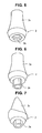
- Fig. 5 is a perspective view of another example of the dental implant abutment according to the present invention.
- Fig. 6 is a perspective view of another example of the dental implant abutment according to the present invention.
- Fig. 7 is a perspective view of another example of the dental implant abutment according to the present invention.
- Fig. 1 is a perspective view of one example of the dental implant abutment according to the present invention.
- Fig. 2 is an explanatory longitudinal sectional view to illustrate a state after completing the dental implant treatment using the dental implant abutment illustrated in Fig. 1 .
- Fig. 3 is a perspective view of another example of the dental implant abutment according to the present invention.
- Fig. 4 is an explanatory longitudinal sectional view to illustrate a state after completing the dental implant treatment using the dental implant abutment illustrated in Fig. 3 .
- Fig. 5 is a perspective view of another example of the dental implant abutment according to the present invention.
- Fig. 6 is a perspective view of another example of the dental implant abutment according to the present invention.
- Fig. 7 is a perspective view of another example of the dental implant abutment according to the present invention.
- the implant fixture 1 is embedded in the jawbone at a lost tooth, and osseously bonded with the jawbone so as to be the artificial tooth root, in the dental implant treatment to recover a lost oral cavity function of a lost tooth.
- the implant fixture 1 has an approximately cylindrical shape as illustrated in Unexamined Japanese Patent Publication No. 07-80003 , or has an approximately cylindrical shape having a male screw provided on an outer periphery thereof as illustrated in Unexamined Japanese Patent Publication No. 2003-325552 .
- the implant fixture 1 has a female screw 1a provided in the axial direction at the center thereof.
- the implant fixture 1 has an engagement part 1b at the oral cavity inner side thereof in order not to rotate the dental implant abutment 2 described below.
- the engagement part 1b is a recessed part having a cross sectional shape agreeing with the prism shape.
- the engagement part 2a provided at the implant fixture 1 side of the dental implant abutment 2 has a recessed part having an angular cross sectional shape such as a hexagon as illustrated in Fig. 5
- the engagement part 1b has a pillar shape agreeing with the angular recessed part.
- the engagement part 1b has a cross sectional shape having recessions at predetermined intervals on an outer periphery of a circular shape. Furthermore, when the engagement part 1b has a pillar shape, it has a through hole communicating with the female screw 1a.
- the dental implant abutment 2 is attached on the oral cavity inner side of the implant fixture 1, which is embedded in the jawbone so as to be the artificial tooth root, and pierces the gingiva so as to be a base of the upper structural body.
- the dental implant abutment 2 is made of a ceramic which is added with a pigment and sintered so as to wholly have a similar color to that of the gingiva. More particularly, the ceramic mainly includes zirconia, and is added with a pigment having a red color or both red and yellow colors and sintered so as to wholly have a similar color to that of the gingiva.
- the dental implant abutment 2 has a prism shape such as a hexagon as illustrated in Figs. 1 and 3 , an angular recessed part having a cross sectional shape such as a hexagon as illustrated in Fig. 5 , or an engagement part 2a in a shape having projections at predetermined intervals on an outer periphery of a pillar shape as illustrated in Fig. 6 , at the opposite side to the oral cavity inner side, in order to be engaged with the engagement part 1b provided on the oral cavity inner side of the implant fixture 1. Further, the dental implant abutment 2 has an oral cavity inner-side engagement part 2b engaged with a prosthesis forming member so as not to rotate at the oral cavity inner side thereof, as illustrated in Figs.
- the prosthesis forming member is constituted of a separate member from the dental implant abutment 2.
- the dental implant abutment 2 is integrally formed with a prosthesis fixing part 2c on the oral cavity inner side of a part which pierces the gingiva, and this prosthesis fixing part 2c has an approximately frustum-shaped outer face, as illustrated in Figs. 3, 4 , 5 and 6 and Unexamined Japanese Patent Publication No. 2003-325552 .
- the dental implant abutment 2 is integrally formed with a prosthesis fixing part 2c having a shape corresponding to a shape of a prosthesis to be produced, as illustrated in Fig. 7 .
- the dental implant abutment 2 when the dental implant abutment 2 is attached by engaging the engagement part 2a on the oral cavity inner side of the implant fixture 1, the dental implant abutment 2 has a shape of expanding toward the oral cavity inner side from outer surface of the implant fixture 1 on an oral cavity inner side, as illustrated in Figs. 1 and 2 , Unexamined Japanese Patent Publication No. 07-80003 and Unexamined Japanese Patent Publication No.
- the dental implant abutment 2 has an oral cavity inner-side end part having a plane shape in which the end part expands toward the oral cavity inner side from an oral cavity inner-side surface of the implant fixture 1, and this oral cavity inner-side end part has a plane shape, or, in another case, the dental implant abutment 2 has a scallop structure in which an interdental papilla side is projected more to the oral cavity inner side in consideration of an interdental papilla, as illustrated in Fig. 7 .
- Examples and comparative examples of dental implant abutments have been produced by using a ceramic material which mainly includes zirconia and is added with only Pigment Red 231 or both Pigment Red 231 and Pigment Yellow 159, and sintering it, and by using a ceramic material which includes only zirconia without addition of a pigment and sintering it.
- Examples 1 to 5 have L* of 60 to 85, a* of 9 to 20 and b* of -5 to 9 in the index of the color system of L*a*b*, and have similar colors to that of the gingiva, where by it is confirmed that aesthetic property is not remarkably damaged even when a patient subjected to the dental implant treatment suffers a retraction of gingiva according to bone absorption.
- Comparative examples 1 to 4 have a* of more than 9, in the index of color system of L*a*b*. Thus, these have hues close to red, and do not have similar colors to that of the gingiva. Further, since b* is more than 9, color saturations are close to yellow, and thus the colors are not similar to that of the gingiva.
- Comparative example 5 without a pigment being added has L* of 95 or more.
- the color of this example is close to white, and in this case, it is clear that aesthetic property is remarkably damaged when a patient subjected to the dental implant treatment suffers a retraction of gingiva according to bone absorption.
Landscapes
- Health & Medical Sciences (AREA)
- Oral & Maxillofacial Surgery (AREA)
- Orthopedic Medicine & Surgery (AREA)
- Dentistry (AREA)
- Epidemiology (AREA)
- Life Sciences & Earth Sciences (AREA)
- Animal Behavior & Ethology (AREA)
- General Health & Medical Sciences (AREA)
- Public Health (AREA)
- Veterinary Medicine (AREA)
- Dental Prosthetics (AREA)
Abstract
To provide a dental implant abutment which is attached on the oral cavity inner side of an implant fixture embedded in a jawbone to be an artificial tooth root and pierces a gingiva so as to be a base of an upper structural body in a dental implant treatment to recover a lost oral cavity function of a lost tooth, and which does not remarkably lose aesthetic property when a patient subjected to the dental implant treatment suffers a retraction of gingiva according to bone absorption, the dental implant abutment is made of a ceramic added with a pigment and sintered so as to wholly have a similar color to that of the gingiva, where the similar color to that of the gingiva has L* of 60 to 85, a* of 9 to 20, and b* of -5 to 9 in an index of a color system of L*a*b*.
Description
- The present invention relates to a dental implant abutment which is attached on the oral cavity inner side of an implant fixture embedded in a jawbone to be an artificial tooth root, and pierces a gingiva so as to be a base of an upper structural body, in a dental implant treatment to recover a lost oral cavity function of a lost tooth, and which does not remarkably lose aesthetic property even when a patient subjected to the dental implant treatment suffers gingival retraction according to bone absorption.
- As a treatment to recover a lost oral cavity function of a lost tooth, a dental implant treatment has been widely used, to fix a dental prosthesis on the oral cavity inner side of an implant fixture which is embedded in a jawbone at a lost tooth and osseously bonded with the jawbone so as to be an artificial tooth root. As for the dental implant treatment, for example, Unexamined Japanese Patent Publication No.
07-80003 2003-325552 U.S. Patent Publication No. 5674072 disclose a generally used conventional structure in which the dental implant abutment to pierce the gingiva is arranged on an oral cavity inner side of the implant fixture, and a dental prosthesis is arranged on the oral cavity inner side of the dental implant abutment. - However, in such the dental implant treatment, a patient subjected to the dental implant treatment suffers bone absorption with the passage of time, and then suffers gingival retraction according to the bone absorption. When the retraction of the gingiva occurs, a part at the oral cavity inner side of the dental implant abutment arranged on the oral cavity inner side of the implant fixture so as to pierce the gingiva is exposed.
- However, a conventional dental implant abutment is formed with titanium or a titanium alloy because of considering bio-compatibility. Thus, when the part at the oral cavity inner side of the dental implant abutment is exposed, the metallic titanium or titanium alloy is seen at the oral cavity inner side of the gingiva. Therefore, aesthetic property is remarkably lost.
- Further, according to recent progression of a dental CAD/CAM technique, a method to produce the dental implant abutment by cutting a ceramic block is widely used. However, this ceramic mainly includes zirconia, and thus have an approximately white color. Thus, when the part at the oral cavity inner side of the dental implant abutment is exposed, the ceramic having an approximately white color is seen at the oral cavity inner side of the gingiva. Therefore, aesthetic property is remarkably damaged.
- When the lip side or cheek side of the dental implant abutment is exposed so as to remarkably damage aesthetic property, it is necessary to change the dental implant abutment to that having a low height, or cut the dental implant abutment and reproduce a prosthesis by collecting occlusion pattern again. However, these treatments are not preferable because corporal and financial burdens of a patient who suffers a retraction of gingiva are great.
- Therefore, as a method to recover a bone-absorbed jawbone or a retracted gingiva, surgical treatments using a gingival transplant, an emdogain, GTR, and GBR were proposed. However, these treatments are not yet realistic, and a burden of a patient who suffers a retraction of gingiva is still great.
- An objective of the present invention is to provide the dental implant abutment which does not lose aesthetic property even when a patient subjected to the dental implant treatment suffers gingival retraction according to bone absorption.
- Present inventors carried out earnest works to solve the above-described problems and, as a result, they found out the followings to complete the present invention. The dental implant abutment is made of a ceramic which is added with a pigment and sintered so as to wholly have a similar color to that of the gingiva. Thereby, even when a patient subjected to the dental implant treatment suffers gingival retraction according to bone absorption so as to expose a part at the oral cavity inner side of the dental implant abutment, aesthetic property is not remarkably damaged because the exposed part has a similar color to that of the gingiva.
- The present invention is the dental implant abutment which is attached on the oral cavity inner side of the implant fixture embedded in the jawbone to be an artificial tooth root, and pierces the gingiva so as to be a base of an upper structural body, wherein the dental implant abutment is made of a ceramic added with a pigment and sintered so as to wholly have a similar color to that of the gingiva.
- The similar color to that of the gingiva has preferably L* of 60 to 85, a* of 9 to 20, and b* of -5 to 9 in an index of a color system of L*a*b*. The dental implant abutment has preferably a prosthesis fixing portion at the oral cavity inner side of a part which pierces the gingiva.
- The dental implant abutment according to the present invention is attached on the oral cavity inner side of the implant fixture embedded in the jawbone to be the artificial tooth root, and pierces the gingiva so as to be a base of the upper structural body, and the dental implant abutment is made of a ceramic added with a pigment and sintered so as to wholly have a similar color to that of the gingiva. Thus, even when a patient subjected to the dental implant treatment suffers a retraction of the gingiva according to bone absorption so as to expose a part at the oral cavity inner side of the dental implant abutment, aesthetic property is not remarkably damaged because the exposed part has a similar color to that of the gingiva. As a result of this, frequencies of a reproduction of a prosthesis, a reoperation of the dental implant treatment, and a surgical treatment of the gingiva, which are carried out to recover aesthetic property, can be reduced.
- Such the effect can be surely achieved when the similar color to that of the gingiva has L* of 60 to 85, a* of 9 to 20, and b* of -5 to 9 in the index of a color system of L*a*b*. Further, in a case that the dental implant abutment has a prosthesis fixing portion at the oral cavity inner side of a part which pierces the gingiva, when the dental implant abutment is produced by cutting a ceramic block by a dental CAD/CAM technique, a prosthesis fixing portion can be simultaneously produced together. Therefore, it is not necessary to separately prepare a member corresponding to the prosthesis fixing portion.
-
Fig. 1 is a perspective view of one example of the dental implant abutment according to the present invention. -
Fig. 2 is an explanatory longitudinal sectional view to illustrate a state after completing the dental implant treatment using the dental implant abutment illustrated inFig. 1 . -
Fig. 3 is a perspective view of another example of the dental implant abutment according to the present invention. -
Fig. 4 is an explanatory longitudinal sectional view to illustrate a state after completing the dental implant treatment using the dental implant abutment illustrated inFig. 3 . -
Fig. 5 is a perspective view of another example of the dental implant abutment according to the present invention. -
Fig. 6 is a perspective view of another example of the dental implant abutment according to the present invention. -
Fig. 7 is a perspective view of another example of the dental implant abutment according to the present invention. - The dental implant abutment according to the present invention will be described in detail below with reference to the drawings.
-
Fig. 1 is a perspective view of one example of the dental implant abutment according to the present invention.Fig. 2 is an explanatory longitudinal sectional view to illustrate a state after completing the dental implant treatment using the dental implant abutment illustrated inFig. 1 .Fig. 3 is a perspective view of another example of the dental implant abutment according to the present invention.Fig. 4 is an explanatory longitudinal sectional view to illustrate a state after completing the dental implant treatment using the dental implant abutment illustrated inFig. 3 .Fig. 5 is a perspective view of another example of the dental implant abutment according to the present invention.Fig. 6 is a perspective view of another example of the dental implant abutment according to the present invention.Fig. 7 is a perspective view of another example of the dental implant abutment according to the present invention. - The
implant fixture 1 is embedded in the jawbone at a lost tooth, and osseously bonded with the jawbone so as to be the artificial tooth root, in the dental implant treatment to recover a lost oral cavity function of a lost tooth. Theimplant fixture 1 has an approximately cylindrical shape as illustrated in Unexamined Japanese Patent Publication No.07-80003 2003-325552 implant fixture 1 has a female screw 1a provided in the axial direction at the center thereof. Theimplant fixture 1 has anengagement part 1b at the oral cavity inner side thereof in order not to rotate thedental implant abutment 2 described below. When anengagement part 2a provided at theimplant fixture 1 side of thedental implant abutment 2 has a prism shape such as a hexagon as illustrated inFigs. 1 and3 , theengagement part 1b is a recessed part having a cross sectional shape agreeing with the prism shape. When theengagement part 2a provided at theimplant fixture 1 side of thedental implant abutment 2 has a recessed part having an angular cross sectional shape such as a hexagon as illustrated inFig. 5 , theengagement part 1b has a pillar shape agreeing with the angular recessed part. Further, when theengagement part 2a provided at theimplant fixture 1 side of thedental implant abutment 2 has a shape having projections at predetermined intervals on an outer periphery of a pillar shape as illustrated inFig. 6 , theengagement part 1b has a cross sectional shape having recessions at predetermined intervals on an outer periphery of a circular shape. Furthermore, when theengagement part 1b has a pillar shape, it has a through hole communicating with the female screw 1a. - The
dental implant abutment 2 according to the present invention is attached on the oral cavity inner side of theimplant fixture 1, which is embedded in the jawbone so as to be the artificial tooth root, and pierces the gingiva so as to be a base of the upper structural body. Thedental implant abutment 2 is made of a ceramic which is added with a pigment and sintered so as to wholly have a similar color to that of the gingiva. More particularly, the ceramic mainly includes zirconia, and is added with a pigment having a red color or both red and yellow colors and sintered so as to wholly have a similar color to that of the gingiva. - The
dental implant abutment 2 has a prism shape such as a hexagon as illustrated inFigs. 1 and3 , an angular recessed part having a cross sectional shape such as a hexagon as illustrated inFig. 5 , or anengagement part 2a in a shape having projections at predetermined intervals on an outer periphery of a pillar shape as illustrated inFig. 6 , at the opposite side to the oral cavity inner side, in order to be engaged with theengagement part 1b provided on the oral cavity inner side of theimplant fixture 1. Further, thedental implant abutment 2 has an oral cavity inner-side engagement part 2b engaged with a prosthesis forming member so as not to rotate at the oral cavity inner side thereof, as illustrated inFigs. 1 and 2 and Unexamined Japanese Patent Publication No.H07-80003 dental implant abutment 2. Or, in another type, thedental implant abutment 2 is integrally formed with aprosthesis fixing part 2c on the oral cavity inner side of a part which pierces the gingiva, and thisprosthesis fixing part 2c has an approximately frustum-shaped outer face, as illustrated inFigs. 3, 4 ,5 and 6 and Unexamined Japanese Patent Publication No.2003-325552 dental implant abutment 2 is integrally formed with aprosthesis fixing part 2c having a shape corresponding to a shape of a prosthesis to be produced, as illustrated inFig. 7 . Further, when thedental implant abutment 2 is attached by engaging theengagement part 2a on the oral cavity inner side of theimplant fixture 1, thedental implant abutment 2 has a shape of expanding toward the oral cavity inner side from outer surface of theimplant fixture 1 on an oral cavity inner side, as illustrated inFigs. 1 and 2 , Unexamined Japanese Patent Publication No.07-80003 2003-325552 implant fixture 1 as illustratedFig. 4 andU.S. Patent No. 5674072 . Furthermore, thedental implant abutment 2 has an oral cavity inner-side end part having a plane shape in which the end part expands toward the oral cavity inner side from an oral cavity inner-side surface of theimplant fixture 1, and this oral cavity inner-side end part has a plane shape, or, in another case, thedental implant abutment 2 has a scallop structure in which an interdental papilla side is projected more to the oral cavity inner side in consideration of an interdental papilla, as illustrated inFig. 7 . - Examples and comparative examples of dental implant abutments have been produced by using a ceramic material which mainly includes zirconia and is added with only Pigment Red 231 or both Pigment Red 231 and Pigment Yellow 159, and sintering it, and by using a ceramic material which includes only zirconia without addition of a pigment and sintering it.
- The results of L*, a* and b* in the index of the color system of L*a*b* of these dental implant abutments are obtained and shown in Table 1.
- As a result, Examples 1 to 5 have L* of 60 to 85, a* of 9 to 20 and b* of -5 to 9 in the index of the color system of L*a*b*, and have similar colors to that of the gingiva, where by it is confirmed that aesthetic property is not remarkably damaged even when a patient subjected to the dental implant treatment suffers a retraction of gingiva according to bone absorption. However, Comparative examples 1 to 4 have a* of more than 9, in the index of color system of L*a*b*. Thus, these have hues close to red, and do not have similar colors to that of the gingiva. Further, since b* is more than 9, color saturations are close to yellow, and thus the colors are not similar to that of the gingiva. Comparative example 5 without a pigment being added has L* of 95 or more. Thus, the color of this example is close to white, and in this case, it is clear that aesthetic property is remarkably damaged when a patient subjected to the dental implant treatment suffers a retraction of gingiva according to bone absorption.
[Table 1] Examples Color measurement result A: Properest B: Proper C: Improper Pigment (Color Index Generic Name) Amount of Addition (wt%) Measurement Conditions L* a* b* Effects Example 1 Pigment Red 231 0.50 White Background 75.5 12.2 1.2 A Pigment Yellow 159 - Black Background 74.8 12.0 0.6 Example 2 Pigment Red 231 1.00 White Background 71.7 12.0 1.2 A Pigment Yellow 159 - Black Background 68.9 12.0 -0.5 Example 3 Pigment Red 231 2.00 White Background 69.2 11.8 0.8 A Pigment Yellow 159 - Black Background 66.3 12.8 -1.0 Example 4 Pigment Red 231 0.90 White Background 73.2 9.5 5.5 A Pigment Yellow 159 0.10 Black Background 73.3 9.5 5.5 Example 5 Pigment Red 231 0.80 White Background 73.6 9.1 7.0 B Pigment Yellow 159 0.20 Black Background 73.2 9.1 6.7 Comparative example 1 Pigment Red 231 0.67 White Background 74.2 7.8 9.6 C Pigment Yellow 159 0.33 Black Background 73.9 7.6 9.4 Comparative example 2 Pigment Red 231 0.50 Background 76.2 6.4 13.9 C Pigment Yellow 159 0.50 Black Background 75.8 6.3 13.4 Comparative example 3 Pigment Red 231 0.10 White Background 83.6 4.6 15.3 C Pigment Yellow 159 0.30 Black Background 83.6 4.6 15.3 Comparative example 4 Pigment Red 231 0.17 White Background 83.0 3.8 17.3 C Pigment Yellow 159 0.33 Black Background 67.1 2.6 14.5 Comparative example 5 Not colored - White Background 97.4 -0.9 2.7 C Black Background 95.2 -1.0 1.4
Claims (3)
- A dental implant abutment which is attached on the oral cavity inner side of an implant fixture embedded in a jawbone to be an artificial tooth root, and pierces a gingiva so as to be a base of an upper structural body, wherein the abutment is made of a ceramic added with a pigment and sintered so as to wholly have a similar color to that of the gingiva.
- The dental implant abutment as claimed in claim 1,
wherein the similar color to that of the gingiva has L* of 60 to 85, a* of 9 to 20, and b* of -5 to 9 in an index of a color system of L*a*b*. - The dental implant abutment as claimed in claim 1 or 2,
wherein the abutment has a prosthesis fixing member at the oral cavity inner side of a part which pierces the gingiva.
Applications Claiming Priority (1)
| Application Number | Priority Date | Filing Date | Title |
|---|---|---|---|
| JP2007251802A JP2009082171A (en) | 2007-09-27 | 2007-09-27 | Dental implant abutment |
Publications (1)
| Publication Number | Publication Date |
|---|---|
| EP2042122A1 true EP2042122A1 (en) | 2009-04-01 |
Family
ID=40229911
Family Applications (1)
| Application Number | Title | Priority Date | Filing Date |
|---|---|---|---|
| EP08016000A Withdrawn EP2042122A1 (en) | 2007-09-27 | 2008-09-11 | Dental implant abutment |
Country Status (3)
| Country | Link |
|---|---|
| US (1) | US20090087815A1 (en) |
| EP (1) | EP2042122A1 (en) |
| JP (1) | JP2009082171A (en) |
Families Citing this family (11)
| Publication number | Priority date | Publication date | Assignee | Title |
|---|---|---|---|---|
| SE530196C2 (en) * | 2004-09-30 | 2008-03-25 | Nobel Biocare Ab | Method and apparatus for effecting coloration or nuance of prosthetics and such prosthetics |
| WO2009111041A1 (en) * | 2008-03-05 | 2009-09-11 | New York University | Metallic dental implants and prosthetic appliances having colored ceramic surfaces |
| DE102009001782A1 (en) * | 2009-03-24 | 2010-09-30 | Sirona Dental Systems Gmbh | gingivaformer |
| FR2948278B1 (en) * | 2009-07-22 | 2011-09-16 | Philippe Dacremont | ADDITIONAL STABILIZATION DEVICE FOR ENDO-BONE DENTAL IMPLANT |
| JP5514991B2 (en) * | 2009-12-10 | 2014-06-04 | 株式会社ナントー精密 | Implant |
| JP5514972B2 (en) * | 2009-12-10 | 2014-06-04 | 株式会社ナントー精密 | Implant |
| ES2566642T3 (en) * | 2010-09-29 | 2016-04-14 | Ivoclar Vivadent Ag | Dental implant system |
| JP2012170723A (en) | 2011-02-23 | 2012-09-10 | Gc Corp | Dental implant abutment made of titanium |
| GB2509136A (en) * | 2012-12-21 | 2014-06-25 | Nobel Biocare Services Ag | Dental component with metal adapter |
| JP5849278B2 (en) | 2013-08-20 | 2016-01-27 | 株式会社ナントー | Prosthesis manufacturing method |
| US12496173B2 (en) | 2020-11-17 | 2025-12-16 | James R. Glidewell Dental Ceramics, Inc. | Method for coloring a dental prosthesis |
Citations (7)
| Publication number | Priority date | Publication date | Assignee | Title |
|---|---|---|---|---|
| JPH0780003A (en) | 1993-09-17 | 1995-03-28 | G C:Kk | Dental prosthetic appliance maintaining device |
| US5674072A (en) | 1994-10-17 | 1997-10-07 | Degussa Aktiengesellschaft | Two-phase tooth implant |
| JP2003325552A (en) | 2002-05-16 | 2003-11-18 | Man Yong Kim | Structure for dental implant |
| US20050084819A1 (en) * | 2003-10-20 | 2005-04-21 | Sims Lawrence O. | Abutment system and method for preparing the same |
| EP1527790A1 (en) * | 2003-10-27 | 2005-05-04 | Straumann Holding AG | Implant with a ceramic coating |
| US20050181330A1 (en) * | 2004-02-17 | 2005-08-18 | Kim Soo H. | Abutment of dental implant and aesthetic surface treatment method of the same |
| DE202007005474U1 (en) * | 2007-04-16 | 2007-06-28 | Straumann Holding Ag | Gingiva shaper for dental implant is made with mixture of Polyetheretherketon base material of 95 to 99 percentage weight component and coloring of 1 to 5 percentage weight component so that gingiva shaper is flesh colored |
-
2007
- 2007-09-27 JP JP2007251802A patent/JP2009082171A/en active Pending
-
2008
- 2008-09-11 EP EP08016000A patent/EP2042122A1/en not_active Withdrawn
- 2008-09-15 US US12/210,428 patent/US20090087815A1/en not_active Abandoned
Patent Citations (7)
| Publication number | Priority date | Publication date | Assignee | Title |
|---|---|---|---|---|
| JPH0780003A (en) | 1993-09-17 | 1995-03-28 | G C:Kk | Dental prosthetic appliance maintaining device |
| US5674072A (en) | 1994-10-17 | 1997-10-07 | Degussa Aktiengesellschaft | Two-phase tooth implant |
| JP2003325552A (en) | 2002-05-16 | 2003-11-18 | Man Yong Kim | Structure for dental implant |
| US20050084819A1 (en) * | 2003-10-20 | 2005-04-21 | Sims Lawrence O. | Abutment system and method for preparing the same |
| EP1527790A1 (en) * | 2003-10-27 | 2005-05-04 | Straumann Holding AG | Implant with a ceramic coating |
| US20050181330A1 (en) * | 2004-02-17 | 2005-08-18 | Kim Soo H. | Abutment of dental implant and aesthetic surface treatment method of the same |
| DE202007005474U1 (en) * | 2007-04-16 | 2007-06-28 | Straumann Holding Ag | Gingiva shaper for dental implant is made with mixture of Polyetheretherketon base material of 95 to 99 percentage weight component and coloring of 1 to 5 percentage weight component so that gingiva shaper is flesh colored |
Also Published As
| Publication number | Publication date |
|---|---|
| JP2009082171A (en) | 2009-04-23 |
| US20090087815A1 (en) | 2009-04-02 |
Similar Documents
| Publication | Publication Date | Title |
|---|---|---|
| US20090087815A1 (en) | Dental implant abutment | |
| EP1898830B2 (en) | Dental abutment | |
| KR101539089B1 (en) | Dental prosthesis method using 3d printer | |
| US20060223029A1 (en) | Method and system for fixing removable dentures | |
| US20110014586A1 (en) | Ceramic one-piece dental implant | |
| EP2491887A1 (en) | Dental implant abutment made of titanium | |
| WO2004054464A2 (en) | Abutment for a dental implant, dental implant comprising such an abutment, and method for the production of dentures by means of said dental implant | |
| US20100248187A1 (en) | Dental abutment | |
| EP3964164B1 (en) | Method for producing a dental prosthesis, blank, and dental prosthesis | |
| KR100407796B1 (en) | Prosthetic dentistry for false teeth that is made from pin retented inlay bridge | |
| EP3166530B1 (en) | Dental prostheses cemented onto implants and/or abutments having a reverse margin | |
| KR20150010118A (en) | Manufacturing method of customized dental implant using computer aided design and computer aided manufactuirng | |
| EP2874563B1 (en) | Abutment system for immediate implants for producing a dental prosthesis | |
| KR200178291Y1 (en) | Artificial teeth for dental department | |
| KR100416247B1 (en) | Artificial teeth for dental department | |
| EP2228032A1 (en) | Dental abutment | |
| KR101435544B1 (en) | Crown mounting structure and mounting method of dental implant | |
| JP2011200570A (en) | Ceramic-made dental implant abutment | |
| WO2023017075A1 (en) | Multicolor zirconium oxide blank for dental prostheses | |
| KR101265969B1 (en) | Manufacturing method of customized abutment for implant having enhanced adatation | |
| US20080076092A1 (en) | Abutment coping for dental implant fixture | |
| CN213722548U (en) | Improved prosthesis for screw hole repairing at upper part of implant | |
| KR20160095260A (en) | Dental implant having enhanced adaptation | |
| DE102014105884A1 (en) | gingivaformer | |
| DE10331524A1 (en) | Dental implant |
Legal Events
| Date | Code | Title | Description |
|---|---|---|---|
| PUAI | Public reference made under article 153(3) epc to a published international application that has entered the european phase |
Free format text: ORIGINAL CODE: 0009012 |
|
| AK | Designated contracting states |
Kind code of ref document: A1 Designated state(s): AT BE BG CH CY CZ DE DK EE ES FI FR GB GR HR HU IE IS IT LI LT LU LV MC MT NL NO PL PT RO SE SI SK TR |
|
| AX | Request for extension of the european patent |
Extension state: AL BA MK RS |
|
| AKX | Designation fees paid | ||
| STAA | Information on the status of an ep patent application or granted ep patent |
Free format text: STATUS: THE APPLICATION IS DEEMED TO BE WITHDRAWN |
|
| 18D | Application deemed to be withdrawn |
Effective date: 20091002 |
|
| REG | Reference to a national code |
Ref country code: DE Ref legal event code: 8566 |