EP2042023A1 - A mower with a conveyor belt - Google Patents
A mower with a conveyor belt Download PDFInfo
- Publication number
- EP2042023A1 EP2042023A1 EP08165362A EP08165362A EP2042023A1 EP 2042023 A1 EP2042023 A1 EP 2042023A1 EP 08165362 A EP08165362 A EP 08165362A EP 08165362 A EP08165362 A EP 08165362A EP 2042023 A1 EP2042023 A1 EP 2042023A1
- Authority
- EP
- European Patent Office
- Prior art keywords
- conveyor
- rollers
- belt
- conveyor belts
- roller
- Prior art date
- Legal status (The legal status is an assumption and is not a legal conclusion. Google has not performed a legal analysis and makes no representation as to the accuracy of the status listed.)
- Granted
Links
Images


Classifications
-
- A—HUMAN NECESSITIES
- A01—AGRICULTURE; FORESTRY; ANIMAL HUSBANDRY; HUNTING; TRAPPING; FISHING
- A01D—HARVESTING; MOWING
- A01D57/00—Delivering mechanisms for harvesters or mowers
- A01D57/20—Delivering mechanisms for harvesters or mowers with conveyor belts
Definitions
- the present invention relates to a mower comprising a mowing aggregate with a number of cutting aggregates and a conditioning device behind the row of cutting aggregates relative to a direction of advance during operation, and comprising belt conveyor means behind the mowing aggregate, comprising a conveyor belt running in a conveying direction over two rollers mounted in a conveyor frame, at least one roller being driven, and at least one roller being movably mounted in the conveyor frame for adjustment of the distance between the rollers.
- mowers so provided with a conveyor belt for conveying mowed crop transversely to the running direction of the mower during work in order to collect crop material mowed over a large width into a relatively narrow swath.
- EP-A-1 616 474 which describes a mower with two mowing aggregates with a very large working width.
- a mower according to the invention is so designed that the belt conveyor means comprise two co-operating, running conveyor belts mounted one after the other in their conveying direction, whereby each of the two conveyor belts, relative to each other, has a proximal roller and a distal roller, that the distal rollers of the conveyor belts are movably mounted in the respective conveyor frames, that the proximal rollers of the conveyor belts are mounted at a fixed mutual distance, and that the rollers of the two conveyor belts are mounted in a joint conveyor frame, or that the respective rollers of the two conveyor belts are mounted in respective conveyor frames fastened rigidly relative to each other with the proximal rollers at a fixed mutual distance.
- Dividing the conveyor belt into two parts in this way eliminates the disadvantages of one long belt.
- the two conveyor belts co-operate in the sense that one conveyor belt delivers conveyed material to the other conveyor belt for further conveying thereby.
- the distal rollers of the conveyor belts are movably mounted in the respective conveyor frames, the distal rollers can be moved to adjust the tension of the conveyor belts without thereby affecting the distance between the two conveyor belts or their proximal rollers, and without thereby affecting the ability of one conveyor belt to deliver material to the other conveyor belt.
- the rollers of the two conveyor belts are mounted in a joint conveyor frame. This makes it possible to obtain a simple construction of the conveyor means.
- the respective rollers of the two conveyor belts may be mounted in respective conveyor frames, wherein the two conveyor frames are rigidly fastened relative to each other with the proximal rollers at a fixed mutual distance, at least in a working position. This makes it possible to obtain a certain flexibility of the conveyor means.
- DE-U-299 19 023 describes a mower with a conditioning device and a belt conveyor for conveying mowed crop transversely to the running direction of the mower during work.
- the belt conveyor has an extension in the form of a short conveyor belt swingably fastened to the belt conveyor in order to be able to control where crop is placed on the field relative to the path of the mower.
- only one conveyor belt receives mowed crop directly from the conditioning device.
- CA-A-1 215 846 describes a header for a harvester with a number of cutting aggregates and belt conveyor means directly behind the cutting aggregates.
- the belt conveyor means comprise two belt conveyors which can be individually displaced transversely to the running direction of the harvester and can turn their respective conveying directions in order to place mowed crop optionally to one side, to the other side, or centrally.
- EP-A-1 849 349 constitutes prior art under Article 54(3) EPC and describes a harvester with a header comprising a number of cutting aggregates and belt conveyor means directly behind the cutting aggregates.
- the movable rollers may be releasably fastenable. Accordingly, the conveyor belt, when loaded, is substantially deflected by its own elastic extension only.
- the proximal rollers of the two conveyor belts are preferably driven. This makes it possible to adjust the distance between the rollers of a conveyor belt by moving the distal roller without thereby involving the driven roller and the pertaining drive.
- the two driven rollers may be driven by respective motors.
- the two driven rollers may be driven by a joint motor through a transmission. The latter is particularly practical when the proximal rollers are permanently fastened at a fixed mutual distance.
- a mower 1 according to the invention and shown in Figs. 1 to 4 has a tractor frame in the form of a T-shaped running frame 2 with a leg 3 and a crossbeam 4 in the T. At the ends of the crossbeam 4 ground wheels 5 are provided, said wheels carrying the mower 1 at least partially. At the front end of the leg 3 a connection device 6 is provided for connecting the mower 1 with a tractor (not shown) for towing and possibly also for partially carrying the mower 1.
- the mower 1 comprises two mowing aggregates 8, of which only the left one is shown in Fig. 4 , while both are shown in Figs. 1 to 3 .
- the mowing aggregates 8 are mounted on the running frame 2 substantially symmetrically about a vertical plane through the leg 3.
- each mowing aggregate 8 is mounted by a first hinge 9 with a substantially vertical axis about which the mowing aggregate 8 can swing in a horizontal plane between a working position ( Fig. 1 ) or an intermediate position ( Fig. 2 ) and a transport position ( Figs. 3 and 4 ).
- each of the mowing aggregates 8 extends laterally from the running frame 2, and in the transport position each of the mowing aggregates 8 extends rearwards, as will be explained in detail below.
- Each of the mowing aggregates 8 has a front and a rear relative to the running direction (arrow A) in the working position and comprises a frame structure 10 extending over the working width of the mowing aggregate 8.
- a beam 11 extends between a second hinge 12, which connects the beam 11 with the frame structure 10, and a third hinge 13 placed close to the first hinge 9, se Fig. 4 in particular.
- the second hinge 12 and the third hinge 13 each has a substantially horizontal hinge axis extending transversely to the beam 11. By swinging about the third hinge 13, the beam 11 can lift the mowing aggregate 8 from the ground.
- a power means is provided, such as a hydraulic cylinder, to swing the beam 11 and lift the mowing aggregate 8.
- a spring 11a is provided to act on the beam 11 in order to relieve the pressure of the mowing aggregate 8 against the ground to a desired pressure.
- the mowing aggregate 8 may adjust itself to the contour of the ground where it is uneven, in a manner known per se.
- the mowing aggregate 8 comprises cutting aggregates, not shown, in the form of a number of cutter discs mounted on a cutter bar extending in the working width transversely to the running direction A ( Fig. 1 ). Under the cutter bar, slide shoes 14 are provided which slide across the ground during operation and carry the part of the weight of the mowing aggregate not carried by the running frame 2.
- a conditioning rotor not shown, is provided behind the mowing means. The rotor may be of the type which, at its ends, has screw portions which can convey material cut by the mowing means towards the centre portion of the conditioning rotor where crimping fingers are provided which crimp or condition the material and throw it to the rear.
- the mowing aggregates comprise a safety screen with side portions 15 and a safety cloth 18.
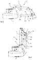
- the mowing aggregate 8 is shown in further detail in Figs. 5 and 6 and is provided with a lateral conveyor 16 arranged behind the mowing aggregate 8 and hinged to the frame structure 10 by means of two carrier arms 17. Thereby, the lateral conveyor 16 may be swung between the working position shown in Figs. 1 and 5 and the transport position shown in Figs. 2 to 4 and 6 .
- the mowing aggregate 8 with lateral conveyor is shown in an intermediate position in which the lateral conveyor 16 is in a transport position, but in which the actual mowing aggregate 8 has been swung out into a working position.
- the mowing aggregate 8 has been swung in so that it projects rearwards relative to the running direction and assumes its transport position resting on two abutments 19 on the running frame 2.
- the lateral conveyor 16 may receive material thrown by the conditioning rotor and convey it laterally towards the centre line of the mower 1 (the leg 3).
- the lateral conveyor 16 comprises a conveyor aggregate 16a, which has a conveyor belt, and which has a front edge 16b and a rear edge 16c.
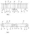
- the conveyor aggregate 16a is illustrated in further detail in Figs. 7 and 8 and comprises two linked, uniformly built, but mutually mirrored belt conveyors together constituting the belt conveyor means of the mower.
- Each of the two belt conveyors comprises a conveyor frame with frame side portions 20 receiving shaft ends 21, 22 of a proximal roller 23 and a distal roller 24, respectively.
- a belt 25 provided with transverse carriers 26 for material to be conveyed runs around the two rollers 23, 24. The two rollers thus constitute turning rollers for the belt.
- the position of the proximal rollers 23 relative to the frame side portions 20 is fixed, whereas the shaft ends 22 of the distal rollers 24 are received in longitudinal holes 27 so that the position of the distal rollers 24 and thereby their distance from the proximal rollers 23 can be adjusted to tension the belts 25.
- Fig. 8 shows the belt conveyors from one side, and that there are corresponding frame side portions not shown in Fig. 8 on their opposite other side.
- the two belt conveyors are mutually connected by fishplates 28, only the closest one of which is shown in Fig. 8 , and which keep the shaft ends 21 and thereby the proximal rollers 23 at a fixed mutual distance.
- the fishplates 28 may be rigidly connected to the frame side portions 20 so that the latter cannot be moved relative to each other, or a limited turning of the fishplates about the shaft ends 21 relative to the frame side portions may be possible.
- the respective frame side portions of the two belt conveyors may be formed integrally.
- Fig. 7 shows a view of the two belt conveyors from the top downwards (direction VII in Fig. 8 ).
- the frame side portions and the rollers are not visible in Fig. 7 as they are hidden by side screens 29 and belts 25.
- the side screens 29 are provided to prevent material being conveyed from penetrating between the belt and the rollers.
- each of the two belt conveyors at its rear edge 16c, has carrier brackets 30 fastened to one frame side portion.
- a carrier beam 31 for fastening carrier arms 17 extends between the respective carrier brackets 30.
- One of the carrier brackets 30 and one of the carrier beams 31 are also seen in Figs. 5 and 6 .
- the carrier arms 17 are movable as described in further detail in a concurrent patent application by the same applicant.
- the two belt conveyors are provided with respective motors 32 each driving a respective one of the proximal rollers 23.
- the motors 32 may, for example, be electric or hydraulic and are supplied with power from a source, not shown.
- the two belt conveyors are located in a common plane. As further appears from Figs. 7 and 8 , the two belt conveyors are substantially of the same length.
- the two belt conveyors act as one long belt conveyor, together being able to convey material transversely to the entire working width of the mowing aggregate.
- problems that may arise in connection with a long conveyor belt, for example in connection with tightening of a long conveyor belt, are avoided.
Landscapes
- Life Sciences & Earth Sciences (AREA)
- Environmental Sciences (AREA)
- Harvester Elements (AREA)
Abstract
Description
- The present invention relates to a mower comprising a mowing aggregate with a number of cutting aggregates and a conditioning device behind the row of cutting aggregates relative to a direction of advance during operation, and comprising belt conveyor means behind the mowing aggregate, comprising a conveyor belt running in a conveying direction over two rollers mounted in a conveyor frame, at least one roller being driven, and at least one roller being movably mounted in the conveyor frame for adjustment of the distance between the rollers.
- There are various examples of mowers so provided with a conveyor belt for conveying mowed crop transversely to the running direction of the mower during work in order to collect crop material mowed over a large width into a relatively narrow swath.
- One example is disclosed in
EP-A-1 616 474 , which describes a mower with two mowing aggregates with a very large working width. - It is known that running conveyor belts become worn and stretched during operation so that they become longer, and that two conveyor belts are usually not exactly the same length due to manufacturing tolerances, and therefore a replacement belt, when exchanged, is usually not of the same length as the original belt. It is therefore common that one of the two rollers (the turning rollers) over which a conveyor belt runs is mounted movably.
- It is a continuous wish to provide mowers with a larger working width to make it possible to harvest a field faster with fewer passes.
- If a conveyor belt is constructed to be very long, problems may arise in connection with adjustment of the distance between the turning rollers and the forces involved for the adjustment.
- To avoid this problem, a mower according to the invention is so designed that the belt conveyor means comprise two co-operating, running conveyor belts mounted one after the other in their conveying direction, whereby each of the two conveyor belts, relative to each other, has a proximal roller and a distal roller, that the distal rollers of the conveyor belts are movably mounted in the respective conveyor frames, that the proximal rollers of the conveyor belts are mounted at a fixed mutual distance, and that the rollers of the two conveyor belts are mounted in a joint conveyor frame, or that the respective rollers of the two conveyor belts are mounted in respective conveyor frames fastened rigidly relative to each other with the proximal rollers at a fixed mutual distance. Dividing the conveyor belt into two parts in this way eliminates the disadvantages of one long belt. The two conveyor belts co-operate in the sense that one conveyor belt delivers conveyed material to the other conveyor belt for further conveying thereby.
- As the distal rollers of the conveyor belts are movably mounted in the respective conveyor frames, the distal rollers can be moved to adjust the tension of the conveyor belts without thereby affecting the distance between the two conveyor belts or their proximal rollers, and without thereby affecting the ability of one conveyor belt to deliver material to the other conveyor belt.
- In one embodiment, the rollers of the two conveyor belts are mounted in a joint conveyor frame. This makes it possible to obtain a simple construction of the conveyor means.
- Alternatively, the respective rollers of the two conveyor belts may be mounted in respective conveyor frames, wherein the two conveyor frames are rigidly fastened relative to each other with the proximal rollers at a fixed mutual distance, at least in a working position. This makes it possible to obtain a certain flexibility of the conveyor means.
-
DE-U-299 19 023 describes a mower with a conditioning device and a belt conveyor for conveying mowed crop transversely to the running direction of the mower during work. The belt conveyor has an extension in the form of a short conveyor belt swingably fastened to the belt conveyor in order to be able to control where crop is placed on the field relative to the path of the mower. As opposed to the present invention, only one conveyor belt receives mowed crop directly from the conditioning device. -
CA-A-1 215 846 describes a header for a harvester with a number of cutting aggregates and belt conveyor means directly behind the cutting aggregates. The belt conveyor means comprise two belt conveyors which can be individually displaced transversely to the running direction of the harvester and can turn their respective conveying directions in order to place mowed crop optionally to one side, to the other side, or centrally. -
EP-A-1 849 349 constitutes prior art under Article 54(3) EPC and describes a harvester with a header comprising a number of cutting aggregates and belt conveyor means directly behind the cutting aggregates. - According to the present invention, the movable rollers may be releasably fastenable. Accordingly, the conveyor belt, when loaded, is substantially deflected by its own elastic extension only.
- The proximal rollers of the two conveyor belts are preferably driven. This makes it possible to adjust the distance between the rollers of a conveyor belt by moving the distal roller without thereby involving the driven roller and the pertaining drive.
- The two driven rollers may be driven by respective motors. Alternatively, the two driven rollers may be driven by a joint motor through a transmission. The latter is particularly practical when the proximal rollers are permanently fastened at a fixed mutual distance.
- The invention will now be described in more detail below by means of an example of an embodiment and with reference to the schematic drawing, in which
-
Fig. 1 is a top view of an embodiment of a mower according to the invention in a working position, -
Fig. 2 is a view corresponding to that ofFig. 1 , in which the mower is in an intermediate position, -
Fig. 3 is a view corresponding to that ofFig. 1 , in which the mower is in a transport position, -
Fig. 4 is a side view of the mower according toFig. 1 in the transport position shown inFig. 3 , -
Fig. 5 is a view seen from the end of a mowing aggregate with a lateral conveyor of the mower according toFig. 1 in a working position corresponding to the working position of the mower ofFig. 1 , -
Fig. 6 is a view corresponding to that ofFig. 5 , in which the lateral conveyor is in a transport position corresponding to the intermediate position and the transport position of the mower as shown inFigs. 2 and3 , respectively, -
Fig. 7 shows a conveyor aggregate of the lateral conveyor, and -
Fig. 8 is a schematic side view showing the frame structure of the conveyor aggregate. - A
mower 1 according to the invention and shown inFigs. 1 to 4 has a tractor frame in the form of a T-shaped runningframe 2 with aleg 3 and a crossbeam 4 in the T. At the ends of the crossbeam 4ground wheels 5 are provided, said wheels carrying themower 1 at least partially. At the front end of the leg 3 aconnection device 6 is provided for connecting themower 1 with a tractor (not shown) for towing and possibly also for partially carrying themower 1. - The
mower 1 comprises twomowing aggregates 8, of which only the left one is shown inFig. 4 , while both are shown inFigs. 1 to 3 . Themowing aggregates 8 are mounted on the runningframe 2 substantially symmetrically about a vertical plane through theleg 3. Thus, eachmowing aggregate 8 is mounted by afirst hinge 9 with a substantially vertical axis about which themowing aggregate 8 can swing in a horizontal plane between a working position (Fig. 1 ) or an intermediate position (Fig. 2 ) and a transport position (Figs. 3 and 4 ). In the working position and the intermediate position of themower 1, each of themowing aggregates 8 extends laterally from the runningframe 2, and in the transport position each of themowing aggregates 8 extends rearwards, as will be explained in detail below. - Each of the
mowing aggregates 8 has a front and a rear relative to the running direction (arrow A) in the working position and comprises aframe structure 10 extending over the working width of themowing aggregate 8. Abeam 11 extends between a second hinge 12, which connects thebeam 11 with theframe structure 10, and athird hinge 13 placed close to thefirst hinge 9, seFig. 4 in particular. The second hinge 12 and thethird hinge 13 each has a substantially horizontal hinge axis extending transversely to thebeam 11. By swinging about thethird hinge 13, thebeam 11 can lift themowing aggregate 8 from the ground. A power means, not shown, is provided, such as a hydraulic cylinder, to swing thebeam 11 and lift themowing aggregate 8. Furthermore, aspring 11a is provided to act on thebeam 11 in order to relieve the pressure of themowing aggregate 8 against the ground to a desired pressure. By swinging about the second hinge 12, themowing aggregate 8 may adjust itself to the contour of the ground where it is uneven, in a manner known per se. - In addition to what has already been mentioned, the
mowing aggregate 8 comprises cutting aggregates, not shown, in the form of a number of cutter discs mounted on a cutter bar extending in the working width transversely to the running direction A (Fig. 1 ). Under the cutter bar,slide shoes 14 are provided which slide across the ground during operation and carry the part of the weight of the mowing aggregate not carried by the runningframe 2. A conditioning rotor, not shown, is provided behind the mowing means. The rotor may be of the type which, at its ends, has screw portions which can convey material cut by the mowing means towards the centre portion of the conditioning rotor where crimping fingers are provided which crimp or condition the material and throw it to the rear. - In a manner known per se, the mowing aggregates comprise a safety screen with
side portions 15 and asafety cloth 18. - The
mowing aggregate 8 is shown in further detail inFigs. 5 and 6 and is provided with alateral conveyor 16 arranged behind themowing aggregate 8 and hinged to theframe structure 10 by means of twocarrier arms 17. Thereby, thelateral conveyor 16 may be swung between the working position shown inFigs. 1 and5 and the transport position shown inFigs. 2 to 4 and6 . InFig. 2 , themowing aggregate 8 with lateral conveyor is shown in an intermediate position in which thelateral conveyor 16 is in a transport position, but in which theactual mowing aggregate 8 has been swung out into a working position. InFigs. 3 and 4 , themowing aggregate 8 has been swung in so that it projects rearwards relative to the running direction and assumes its transport position resting on twoabutments 19 on the runningframe 2. - In its active working position, the
lateral conveyor 16 may receive material thrown by the conditioning rotor and convey it laterally towards the centre line of the mower 1 (the leg 3). Thelateral conveyor 16 comprises aconveyor aggregate 16a, which has a conveyor belt, and which has afront edge 16b and arear edge 16c. - The
conveyor aggregate 16a is illustrated in further detail inFigs. 7 and 8 and comprises two linked, uniformly built, but mutually mirrored belt conveyors together constituting the belt conveyor means of the mower. Each of the two belt conveyors comprises a conveyor frame withframe side portions 20 receivingshaft ends proximal roller 23 and adistal roller 24, respectively. Abelt 25 provided withtransverse carriers 26 for material to be conveyed runs around the tworollers proximal rollers 23 relative to theframe side portions 20 is fixed, whereas the shaft ends 22 of thedistal rollers 24 are received inlongitudinal holes 27 so that the position of thedistal rollers 24 and thereby their distance from theproximal rollers 23 can be adjusted to tension thebelts 25. - It should be understood that
Fig. 8 shows the belt conveyors from one side, and that there are corresponding frame side portions not shown inFig. 8 on their opposite other side. - As shown in
Fig. 8 , the two belt conveyors are mutually connected byfishplates 28, only the closest one of which is shown inFig. 8 , and which keep the shaft ends 21 and thereby theproximal rollers 23 at a fixed mutual distance. Thefishplates 28 may be rigidly connected to theframe side portions 20 so that the latter cannot be moved relative to each other, or a limited turning of the fishplates about the shaft ends 21 relative to the frame side portions may be possible. As an alternative to rigidly connected fishplates, the respective frame side portions of the two belt conveyors may be formed integrally. -
Fig. 7 shows a view of the two belt conveyors from the top downwards (direction VII inFig. 8 ). The frame side portions and the rollers are not visible inFig. 7 as they are hidden byside screens 29 andbelts 25. The side screens 29 are provided to prevent material being conveyed from penetrating between the belt and the rollers. - As shown in
Fig. 7 , each of the two belt conveyors, at itsrear edge 16c, hascarrier brackets 30 fastened to one frame side portion. Acarrier beam 31 forfastening carrier arms 17 extends between therespective carrier brackets 30. One of thecarrier brackets 30 and one of the carrier beams 31 are also seen inFigs. 5 and 6 . As appears from the drawing, thecarrier arms 17 are movable as described in further detail in a concurrent patent application by the same applicant. - As further appears from
Fig. 7 , the two belt conveyors are provided withrespective motors 32 each driving a respective one of theproximal rollers 23. Themotors 32 may, for example, be electric or hydraulic and are supplied with power from a source, not shown. - As particularly appears from
Fig. 8 , the two belt conveyors are located in a common plane. As further appears fromFigs. 7 and 8 , the two belt conveyors are substantially of the same length. - The two belt conveyors act as one long belt conveyor, together being able to convey material transversely to the entire working width of the mowing aggregate. However, the problems that may arise in connection with a long conveyor belt, for example in connection with tightening of a long conveyor belt, are avoided.
Claims (6)
- A mower comprising a mowing aggregate (8) with a number of cutting aggregates and a conditioning device behind the row of cutting aggregates relative to a direction of advance during operation, and comprising belt conveyor means (16) behind the mowing aggregate (8), comprising a conveyor belt (25) running in a conveying direction over two rollers (23, 24) mounted in a conveyor frame (20), at least one roller (23) being driven, and at least one roller (24) being movably mounted in the conveyor frame (20) for adjustment of the distance between the rollers, characterized in that the belt conveyor means (16) comprise two running conveyor belts (25) mounted one after the other in their conveying direction, whereby each of the two conveyor belts (25), relative to each other, has a proximal roller (23) and a distal roller (24), that the distal rollers (24) of the conveyor belts (25) are movably mounted in the respective conveyor frames (20), that the proximal rollers (23) of the conveyor belts are mounted at a fixed mutual distance, and that the rollers of the two conveyor belts are mounted in a joint conveyor frame, or that the respective rollers (23, 24) of the two conveyor belts are mounted in respective conveyor frames (20) fastened rigidly relative to each other with the proximal rollers (23) at a fixed mutual distance.
- A mower according to claim 1, characterized in that the movable rollers (24) are releasably fastenable.
- A mower according to claim 1 or 2, characterized in that the proximal rollers (23) of the two conveyor belts are driven.
- A mower according to claim 3, characterized in that the two driven rollers (23) are driven by respective motors (32).
- A mower according to claim 3, characterized in that the two driven rollers are driven by a joint motor through a transmission.
- A mower according to any one of claims 1 to 5, characterized in that the two conveyor belts are located in a common plane in order to act as one long belt conveyor.
Applications Claiming Priority (1)
| Application Number | Priority Date | Filing Date | Title |
|---|---|---|---|
| DKPA200701401 | 2007-09-28 |
Publications (2)
| Publication Number | Publication Date |
|---|---|
| EP2042023A1 true EP2042023A1 (en) | 2009-04-01 |
| EP2042023B1 EP2042023B1 (en) | 2011-04-20 |
Family
ID=40202130
Family Applications (1)
| Application Number | Title | Priority Date | Filing Date |
|---|---|---|---|
| EP08165362A Active EP2042023B1 (en) | 2007-09-28 | 2008-09-29 | A mower with a conveyor belt |
Country Status (4)
| Country | Link |
|---|---|
| EP (1) | EP2042023B1 (en) |
| AT (1) | ATE505946T1 (en) |
| DE (1) | DE602008006319D1 (en) |
| DK (1) | DK2042023T3 (en) |
Cited By (5)
| Publication number | Priority date | Publication date | Assignee | Title |
|---|---|---|---|---|
| CN103340060A (en) * | 2013-06-24 | 2013-10-09 | 钦州学院 | Sugarcane harvesting conveying mechanism suitable for complex terrains |
| EP2820939A1 (en) * | 2013-07-01 | 2015-01-07 | Kverneland A/S | Rotary tedder |
| EP3763194A1 (en) * | 2019-07-10 | 2021-01-13 | CLAAS Saulgau GmbH | Transverse conveyor for an agricultural harvester |
| EP3973756A1 (en) | 2020-09-29 | 2022-03-30 | Kuhn SAS | Trailed agricultural machine for harvesting with an adjustable axle |
| US20240147907A1 (en) * | 2022-11-09 | 2024-05-09 | Maschinenfabrik Bernard Krone GmbH & Co. KG | Method for adjusting haymaking machine into transport position |
Citations (9)
| Publication number | Priority date | Publication date | Assignee | Title |
|---|---|---|---|---|
| DE456281C (en) * | 1928-02-21 | Philipp Hangen 4 | Depositing device for mowing machines | |
| US1724300A (en) * | 1923-02-05 | 1929-08-13 | Moncreiffe Malcolm | Mower |
| FR1420072A (en) * | 1964-01-23 | 1965-12-03 | Deere & Co | Windrower equipped with shifting and reversing conveyors |
| CA1215846A (en) | 1983-10-18 | 1986-12-30 | Howard R. Lohrentz | Harvesting header with adjustable draper for left, right or center delivery |
| DE29919023U1 (en) | 1999-10-29 | 1999-12-30 | Gebr. Pöttinger GmbH, 86899 Landsberg | Swathing device with additional belt |
| DE20012446U1 (en) * | 2000-07-18 | 2000-11-30 | Fella-Werke GmbH & Co. KG, 90537 Feucht | Agricultural machine |
| US6164051A (en) * | 1996-08-06 | 2000-12-26 | Maasland N.V. | Machine combination, a rake and pick-up and displacing member, as well as a method |
| EP1616474A1 (en) | 2004-07-07 | 2006-01-18 | JF-Fabriken - J. Freudendahl A/S | A towed mower comprising a running frame and two mowing aggregates |
| EP1849349A1 (en) | 2006-04-26 | 2007-10-31 | Deere & Company | Dual belt drive for an agricultural header |
-
2008
- 2008-09-29 AT AT08165362T patent/ATE505946T1/en active
- 2008-09-29 EP EP08165362A patent/EP2042023B1/en active Active
- 2008-09-29 DK DK08165362.8T patent/DK2042023T3/en active
- 2008-09-29 DE DE602008006319T patent/DE602008006319D1/en active Active
Patent Citations (9)
| Publication number | Priority date | Publication date | Assignee | Title |
|---|---|---|---|---|
| DE456281C (en) * | 1928-02-21 | Philipp Hangen 4 | Depositing device for mowing machines | |
| US1724300A (en) * | 1923-02-05 | 1929-08-13 | Moncreiffe Malcolm | Mower |
| FR1420072A (en) * | 1964-01-23 | 1965-12-03 | Deere & Co | Windrower equipped with shifting and reversing conveyors |
| CA1215846A (en) | 1983-10-18 | 1986-12-30 | Howard R. Lohrentz | Harvesting header with adjustable draper for left, right or center delivery |
| US6164051A (en) * | 1996-08-06 | 2000-12-26 | Maasland N.V. | Machine combination, a rake and pick-up and displacing member, as well as a method |
| DE29919023U1 (en) | 1999-10-29 | 1999-12-30 | Gebr. Pöttinger GmbH, 86899 Landsberg | Swathing device with additional belt |
| DE20012446U1 (en) * | 2000-07-18 | 2000-11-30 | Fella-Werke GmbH & Co. KG, 90537 Feucht | Agricultural machine |
| EP1616474A1 (en) | 2004-07-07 | 2006-01-18 | JF-Fabriken - J. Freudendahl A/S | A towed mower comprising a running frame and two mowing aggregates |
| EP1849349A1 (en) | 2006-04-26 | 2007-10-31 | Deere & Company | Dual belt drive for an agricultural header |
Cited By (8)
| Publication number | Priority date | Publication date | Assignee | Title |
|---|---|---|---|---|
| CN103340060A (en) * | 2013-06-24 | 2013-10-09 | 钦州学院 | Sugarcane harvesting conveying mechanism suitable for complex terrains |
| EP2820939A1 (en) * | 2013-07-01 | 2015-01-07 | Kverneland A/S | Rotary tedder |
| EP3763194A1 (en) * | 2019-07-10 | 2021-01-13 | CLAAS Saulgau GmbH | Transverse conveyor for an agricultural harvester |
| DE102019118740A1 (en) * | 2019-07-10 | 2021-01-14 | Claas Saulgau Gmbh | Cross conveyor of an agricultural harvesting machine |
| EP3973756A1 (en) | 2020-09-29 | 2022-03-30 | Kuhn SAS | Trailed agricultural machine for harvesting with an adjustable axle |
| FR3114479A1 (en) | 2020-09-29 | 2022-04-01 | Kuhn Sas | Trailed agricultural harvesting machine with an adjustable axle |
| US20240147907A1 (en) * | 2022-11-09 | 2024-05-09 | Maschinenfabrik Bernard Krone GmbH & Co. KG | Method for adjusting haymaking machine into transport position |
| EP4367996A1 (en) * | 2022-11-09 | 2024-05-15 | Maschinenfabrik Bernard Krone GmbH & Co. KG | Method for adjusting a haymaking machine in a transport position |
Also Published As
| Publication number | Publication date |
|---|---|
| DE602008006319D1 (en) | 2011-06-01 |
| EP2042023B1 (en) | 2011-04-20 |
| DK2042023T3 (en) | 2011-05-16 |
| ATE505946T1 (en) | 2011-05-15 |
Similar Documents
| Publication | Publication Date | Title |
|---|---|---|
| CA2640605C (en) | Combine harvester draper header having flexible cutterbar | |
| US4938010A (en) | Harvesting header having adjustable width, draper belt discharge opening | |
| US10743466B2 (en) | Harvesting header for a grain harvesting machine | |
| US8336280B2 (en) | Pivoting center conveyor for draper platform | |
| EP2042023B1 (en) | A mower with a conveyor belt | |
| CA2608789A1 (en) | Mower conditioner having auger flights positioned over a cutter bat to effect clearing thereof | |
| CA2323948C (en) | Mowing implement | |
| EP2042025B1 (en) | A mower with a lateral conveyor | |
| US20220240449A1 (en) | Agricultural header with inter-frame flexible seal | |
| US7823372B1 (en) | Skewed roller conveyor for double windrow attachment | |
| EP1616474B1 (en) | A towed mower comprising a running frame and two mowing aggregates | |
| CA1193449A (en) | Adjustable multiple row crop unit | |
| EP1543713B1 (en) | Harvester | |
| JP2004121164A (en) | Agricultural product harvester |
Legal Events
| Date | Code | Title | Description |
|---|---|---|---|
| PUAI | Public reference made under article 153(3) epc to a published international application that has entered the european phase |
Free format text: ORIGINAL CODE: 0009012 |
|
| AK | Designated contracting states |
Kind code of ref document: A1 Designated state(s): AT BE BG CH CY CZ DE DK EE ES FI FR GB GR HR HU IE IS IT LI LT LU LV MC MT NL NO PL PT RO SE SI SK TR |
|
| AX | Request for extension of the european patent |
Extension state: AL BA MK RS |
|
| 17P | Request for examination filed |
Effective date: 20090929 |
|
| AKX | Designation fees paid |
Designated state(s): AT BE BG CH CY CZ DE DK EE ES FI FR GB GR HR HU IE IS IT LI LT LU LV MC MT NL NO PL PT RO SE SI SK TR |
|
| GRAP | Despatch of communication of intention to grant a patent |
Free format text: ORIGINAL CODE: EPIDOSNIGR1 |
|
| GRAS | Grant fee paid |
Free format text: ORIGINAL CODE: EPIDOSNIGR3 |
|
| GRAA | (expected) grant |
Free format text: ORIGINAL CODE: 0009210 |
|
| AK | Designated contracting states |
Kind code of ref document: B1 Designated state(s): AT BE BG CH CY CZ DE DK EE ES FI FR GB GR HR HU IE IS IT LI LT LU LV MC MT NL NO PL PT RO SE SI SK TR |
|
| REG | Reference to a national code |
Ref country code: GB Ref legal event code: FG4D |
|
| REG | Reference to a national code |
Ref country code: CH Ref legal event code: EP |
|
| REG | Reference to a national code |
Ref country code: DK Ref legal event code: T3 |
|
| REG | Reference to a national code |
Ref country code: IE Ref legal event code: FG4D |
|
| REF | Corresponds to: |
Ref document number: 602008006319 Country of ref document: DE Date of ref document: 20110601 Kind code of ref document: P |
|
| REG | Reference to a national code |
Ref country code: DE Ref legal event code: R096 Ref document number: 602008006319 Country of ref document: DE Effective date: 20110601 |
|
| REG | Reference to a national code |
Ref country code: SE Ref legal event code: TRGR |
|
| REG | Reference to a national code |
Ref country code: NL Ref legal event code: T3 |
|
| LTIE | Lt: invalidation of european patent or patent extension |
Effective date: 20110420 |
|
| PG25 | Lapsed in a contracting state [announced via postgrant information from national office to epo] |
Ref country code: PT Free format text: LAPSE BECAUSE OF FAILURE TO SUBMIT A TRANSLATION OF THE DESCRIPTION OR TO PAY THE FEE WITHIN THE PRESCRIBED TIME-LIMIT Effective date: 20110822 Ref country code: HR Free format text: LAPSE BECAUSE OF FAILURE TO SUBMIT A TRANSLATION OF THE DESCRIPTION OR TO PAY THE FEE WITHIN THE PRESCRIBED TIME-LIMIT Effective date: 20110420 Ref country code: NO Free format text: LAPSE BECAUSE OF FAILURE TO SUBMIT A TRANSLATION OF THE DESCRIPTION OR TO PAY THE FEE WITHIN THE PRESCRIBED TIME-LIMIT Effective date: 20110720 Ref country code: LT Free format text: LAPSE BECAUSE OF FAILURE TO SUBMIT A TRANSLATION OF THE DESCRIPTION OR TO PAY THE FEE WITHIN THE PRESCRIBED TIME-LIMIT Effective date: 20110420 |
|
| PG25 | Lapsed in a contracting state [announced via postgrant information from national office to epo] |
Ref country code: BE Free format text: LAPSE BECAUSE OF FAILURE TO SUBMIT A TRANSLATION OF THE DESCRIPTION OR TO PAY THE FEE WITHIN THE PRESCRIBED TIME-LIMIT Effective date: 20110420 Ref country code: CY Free format text: LAPSE BECAUSE OF FAILURE TO SUBMIT A TRANSLATION OF THE DESCRIPTION OR TO PAY THE FEE WITHIN THE PRESCRIBED TIME-LIMIT Effective date: 20110420 Ref country code: SI Free format text: LAPSE BECAUSE OF FAILURE TO SUBMIT A TRANSLATION OF THE DESCRIPTION OR TO PAY THE FEE WITHIN THE PRESCRIBED TIME-LIMIT Effective date: 20110420 Ref country code: GR Free format text: LAPSE BECAUSE OF FAILURE TO SUBMIT A TRANSLATION OF THE DESCRIPTION OR TO PAY THE FEE WITHIN THE PRESCRIBED TIME-LIMIT Effective date: 20110721 Ref country code: IS Free format text: LAPSE BECAUSE OF FAILURE TO SUBMIT A TRANSLATION OF THE DESCRIPTION OR TO PAY THE FEE WITHIN THE PRESCRIBED TIME-LIMIT Effective date: 20110820 Ref country code: FI Free format text: LAPSE BECAUSE OF FAILURE TO SUBMIT A TRANSLATION OF THE DESCRIPTION OR TO PAY THE FEE WITHIN THE PRESCRIBED TIME-LIMIT Effective date: 20110420 Ref country code: ES Free format text: LAPSE BECAUSE OF FAILURE TO SUBMIT A TRANSLATION OF THE DESCRIPTION OR TO PAY THE FEE WITHIN THE PRESCRIBED TIME-LIMIT Effective date: 20110731 Ref country code: LV Free format text: LAPSE BECAUSE OF FAILURE TO SUBMIT A TRANSLATION OF THE DESCRIPTION OR TO PAY THE FEE WITHIN THE PRESCRIBED TIME-LIMIT Effective date: 20110420 |
|
| REG | Reference to a national code |
Ref country code: NL Ref legal event code: SD Effective date: 20111228 Ref country code: NL Ref legal event code: TD Effective date: 20111228 |
|
| PG25 | Lapsed in a contracting state [announced via postgrant information from national office to epo] |
Ref country code: CZ Free format text: LAPSE BECAUSE OF FAILURE TO SUBMIT A TRANSLATION OF THE DESCRIPTION OR TO PAY THE FEE WITHIN THE PRESCRIBED TIME-LIMIT Effective date: 20110420 Ref country code: EE Free format text: LAPSE BECAUSE OF FAILURE TO SUBMIT A TRANSLATION OF THE DESCRIPTION OR TO PAY THE FEE WITHIN THE PRESCRIBED TIME-LIMIT Effective date: 20110420 |
|
| REG | Reference to a national code |
Ref country code: DE Ref legal event code: R082 Ref document number: 602008006319 Country of ref document: DE Representative=s name: KSNH PATENTANWAELTE KLUNKER & KOLLEGEN, DE |
|
| RAP2 | Party data changed (patent owner data changed or rights of a patent transferred) |
Owner name: KONGSKILDE INDUSTRIES A/S |
|
| PLBE | No opposition filed within time limit |
Free format text: ORIGINAL CODE: 0009261 |
|
| STAA | Information on the status of an ep patent application or granted ep patent |
Free format text: STATUS: NO OPPOSITION FILED WITHIN TIME LIMIT |
|
| PG25 | Lapsed in a contracting state [announced via postgrant information from national office to epo] |
Ref country code: PL Free format text: LAPSE BECAUSE OF FAILURE TO SUBMIT A TRANSLATION OF THE DESCRIPTION OR TO PAY THE FEE WITHIN THE PRESCRIBED TIME-LIMIT Effective date: 20110420 Ref country code: RO Free format text: LAPSE BECAUSE OF FAILURE TO SUBMIT A TRANSLATION OF THE DESCRIPTION OR TO PAY THE FEE WITHIN THE PRESCRIBED TIME-LIMIT Effective date: 20110420 Ref country code: SK Free format text: LAPSE BECAUSE OF FAILURE TO SUBMIT A TRANSLATION OF THE DESCRIPTION OR TO PAY THE FEE WITHIN THE PRESCRIBED TIME-LIMIT Effective date: 20110420 |
|
| REG | Reference to a national code |
Ref country code: DE Ref legal event code: R081 Ref document number: 602008006319 Country of ref document: DE Owner name: KONGSKILDE INDUSTRIES A/S, DK Free format text: FORMER OWNER: JF-FABRIKEN - J. FREUDENDAHL A/S, SOENDERBORG, DK Effective date: 20120201 Ref country code: DE Ref legal event code: R082 Ref document number: 602008006319 Country of ref document: DE Representative=s name: SCHMITT-NILSON SCHRAUD WAIBEL WOHLFROM PATENTA, DE Effective date: 20120201 Ref country code: DE Ref legal event code: R082 Ref document number: 602008006319 Country of ref document: DE Representative=s name: KSNH PATENTANWAELTE KLUNKER/SCHMITT-NILSON/HIR, DE Effective date: 20120201 Ref country code: DE Ref legal event code: R081 Ref document number: 602008006319 Country of ref document: DE Owner name: CNH INDUSTRIAL DANMARK A/S, DK Free format text: FORMER OWNER: JF-FABRIKEN - J. FREUDENDAHL A/S, SOENDERBORG, DK Effective date: 20120201 |
|
| REG | Reference to a national code |
Ref country code: FR Ref legal event code: TP Owner name: KONGSKILDE INDUSTRIES A/S, DK Effective date: 20120217 |
|
| 26N | No opposition filed |
Effective date: 20120123 |
|
| PG25 | Lapsed in a contracting state [announced via postgrant information from national office to epo] |
Ref country code: MC Free format text: LAPSE BECAUSE OF NON-PAYMENT OF DUE FEES Effective date: 20110930 |
|
| REG | Reference to a national code |
Ref country code: DE Ref legal event code: R097 Ref document number: 602008006319 Country of ref document: DE Effective date: 20120123 |
|
| PG25 | Lapsed in a contracting state [announced via postgrant information from national office to epo] |
Ref country code: IT Free format text: LAPSE BECAUSE OF FAILURE TO SUBMIT A TRANSLATION OF THE DESCRIPTION OR TO PAY THE FEE WITHIN THE PRESCRIBED TIME-LIMIT Effective date: 20110420 |
|
| REG | Reference to a national code |
Ref country code: GB Ref legal event code: 732E Free format text: REGISTERED BETWEEN 20120510 AND 20120516 |
|
| REG | Reference to a national code |
Ref country code: IE Ref legal event code: MM4A |
|
| PG25 | Lapsed in a contracting state [announced via postgrant information from national office to epo] |
Ref country code: IE Free format text: LAPSE BECAUSE OF NON-PAYMENT OF DUE FEES Effective date: 20110929 |
|
| REG | Reference to a national code |
Ref country code: AT Ref legal event code: PC Ref document number: 505946 Country of ref document: AT Kind code of ref document: T Owner name: KONGSKILDE INDUSTRIES A/S, DK Effective date: 20121017 |
|
| PG25 | Lapsed in a contracting state [announced via postgrant information from national office to epo] |
Ref country code: MT Free format text: LAPSE BECAUSE OF FAILURE TO SUBMIT A TRANSLATION OF THE DESCRIPTION OR TO PAY THE FEE WITHIN THE PRESCRIBED TIME-LIMIT Effective date: 20110420 |
|
| REG | Reference to a national code |
Ref country code: CH Ref legal event code: PL |
|
| PG25 | Lapsed in a contracting state [announced via postgrant information from national office to epo] |
Ref country code: LU Free format text: LAPSE BECAUSE OF NON-PAYMENT OF DUE FEES Effective date: 20110929 |
|
| PG25 | Lapsed in a contracting state [announced via postgrant information from national office to epo] |
Ref country code: BG Free format text: LAPSE BECAUSE OF FAILURE TO SUBMIT A TRANSLATION OF THE DESCRIPTION OR TO PAY THE FEE WITHIN THE PRESCRIBED TIME-LIMIT Effective date: 20110720 |
|
| PG25 | Lapsed in a contracting state [announced via postgrant information from national office to epo] |
Ref country code: CH Free format text: LAPSE BECAUSE OF NON-PAYMENT OF DUE FEES Effective date: 20120930 Ref country code: LI Free format text: LAPSE BECAUSE OF NON-PAYMENT OF DUE FEES Effective date: 20120930 |
|
| PG25 | Lapsed in a contracting state [announced via postgrant information from national office to epo] |
Ref country code: TR Free format text: LAPSE BECAUSE OF FAILURE TO SUBMIT A TRANSLATION OF THE DESCRIPTION OR TO PAY THE FEE WITHIN THE PRESCRIBED TIME-LIMIT Effective date: 20110420 |
|
| PG25 | Lapsed in a contracting state [announced via postgrant information from national office to epo] |
Ref country code: HU Free format text: LAPSE BECAUSE OF FAILURE TO SUBMIT A TRANSLATION OF THE DESCRIPTION OR TO PAY THE FEE WITHIN THE PRESCRIBED TIME-LIMIT Effective date: 20110420 |
|
| REG | Reference to a national code |
Ref country code: FR Ref legal event code: PLFP Year of fee payment: 8 |
|
| REG | Reference to a national code |
Ref country code: FR Ref legal event code: PLFP Year of fee payment: 9 |
|
| REG | Reference to a national code |
Ref country code: DE Ref legal event code: R081 Ref document number: 602008006319 Country of ref document: DE Owner name: CNH INDUSTRIAL DANMARK A/S, DK Free format text: FORMER OWNER: KONGSKILDE INDUSTRIES A/S, SOROE, DK Ref country code: DE Ref legal event code: R082 Ref document number: 602008006319 Country of ref document: DE Representative=s name: SCHMITT-NILSON SCHRAUD WAIBEL WOHLFROM PATENTA, DE Ref country code: DE Ref legal event code: R082 Ref document number: 602008006319 Country of ref document: DE Representative=s name: KSNH PATENTANWAELTE KLUNKER/SCHMITT-NILSON/HIR, DE |
|
| REG | Reference to a national code |
Ref country code: NL Ref legal event code: PD Owner name: CNH INDUSTRIAL DANMARK A/S; DK Free format text: DETAILS ASSIGNMENT: CHANGE OF OWNER(S), ASSIGNMENT; FORMER OWNER NAME: KONGSKILDE INDUSTRIES A/S Effective date: 20170411 |
|
| REG | Reference to a national code |
Ref country code: GB Ref legal event code: 732E Free format text: REGISTERED BETWEEN 20170601 AND 20170607 |
|
| REG | Reference to a national code |
Ref country code: DE Ref legal event code: R082 Ref document number: 602008006319 Country of ref document: DE Representative=s name: SCHMITT-NILSON SCHRAUD WAIBEL WOHLFROM PATENTA, DE |
|
| REG | Reference to a national code |
Ref country code: AT Ref legal event code: PC Ref document number: 505946 Country of ref document: AT Kind code of ref document: T Owner name: CNH INDUSTRIAL DANMARK A/S, DK Effective date: 20170704 |
|
| REG | Reference to a national code |
Ref country code: FR Ref legal event code: PLFP Year of fee payment: 10 |
|
| REG | Reference to a national code |
Ref country code: FR Ref legal event code: TP Owner name: CNH INDUSTRIAL DANMARK A/S, DK Effective date: 20170829 |
|
| REG | Reference to a national code |
Ref country code: FR Ref legal event code: PLFP Year of fee payment: 11 |
|
| PGFP | Annual fee paid to national office [announced via postgrant information from national office to epo] |
Ref country code: NL Payment date: 20190927 Year of fee payment: 12 |
|
| PGFP | Annual fee paid to national office [announced via postgrant information from national office to epo] |
Ref country code: AT Payment date: 20190926 Year of fee payment: 12 |
|
| REG | Reference to a national code |
Ref country code: NL Ref legal event code: MM Effective date: 20201001 |
|
| REG | Reference to a national code |
Ref country code: AT Ref legal event code: MM01 Ref document number: 505946 Country of ref document: AT Kind code of ref document: T Effective date: 20200929 |
|
| PG25 | Lapsed in a contracting state [announced via postgrant information from national office to epo] |
Ref country code: NL Free format text: LAPSE BECAUSE OF NON-PAYMENT OF DUE FEES Effective date: 20201001 |
|
| PG25 | Lapsed in a contracting state [announced via postgrant information from national office to epo] |
Ref country code: AT Free format text: LAPSE BECAUSE OF NON-PAYMENT OF DUE FEES Effective date: 20200929 |
|
| PGFP | Annual fee paid to national office [announced via postgrant information from national office to epo] |
Ref country code: DK Payment date: 20250924 Year of fee payment: 18 Ref country code: DE Payment date: 20250926 Year of fee payment: 18 |
|
| PGFP | Annual fee paid to national office [announced via postgrant information from national office to epo] |
Ref country code: GB Payment date: 20250923 Year of fee payment: 18 |
|
| PGFP | Annual fee paid to national office [announced via postgrant information from national office to epo] |
Ref country code: FR Payment date: 20250925 Year of fee payment: 18 |
|
| PGFP | Annual fee paid to national office [announced via postgrant information from national office to epo] |
Ref country code: SE Payment date: 20250924 Year of fee payment: 18 |